

Page 1
TO REDUCE THE RISK OF INJURY, USER MUST READ AND UNDERSTAND OPERATOR'S
MANUAL.
OPERATOR'S MANUAL
Cat. No.
8911
8912
8925
8926
8945
8965
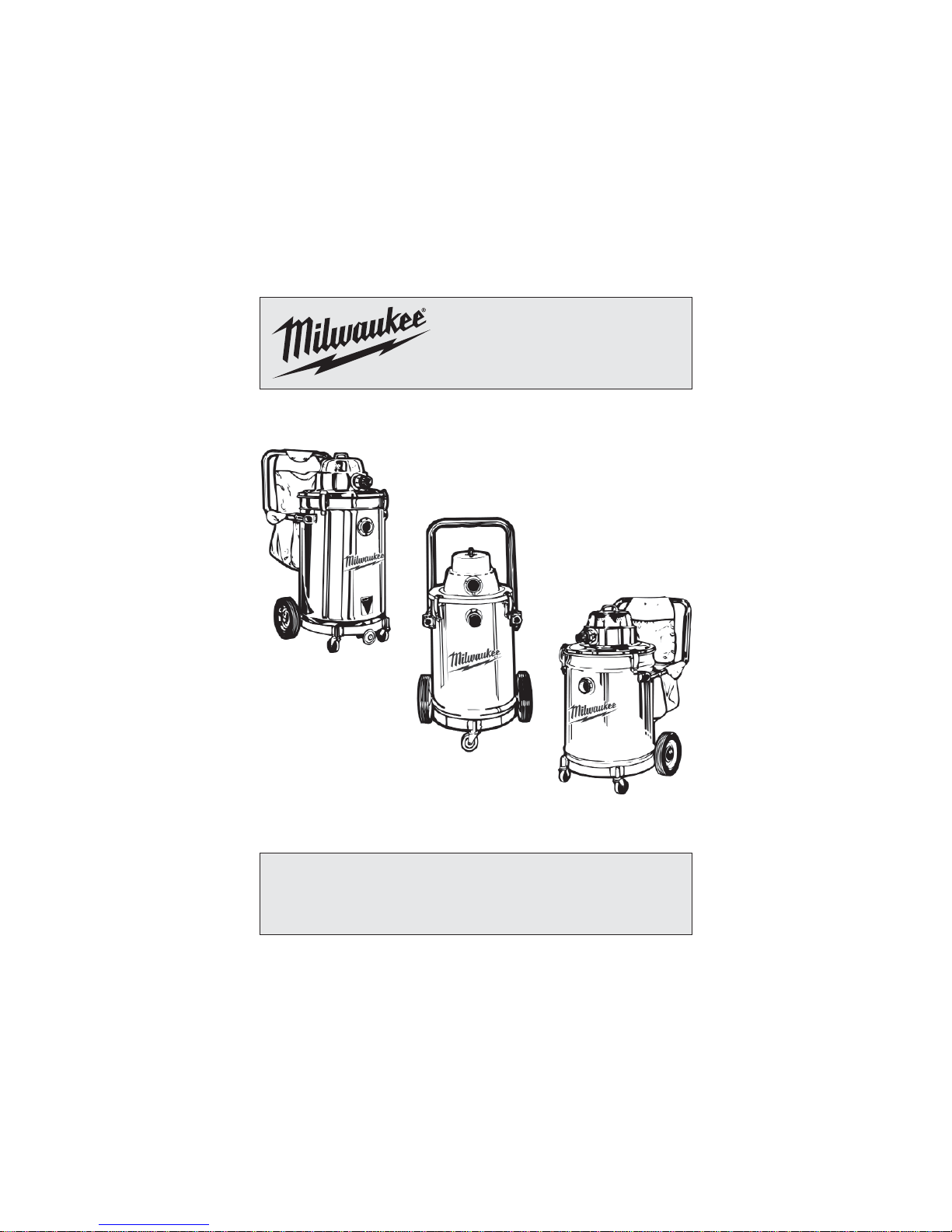
HEAVY-DUTY COMMERCIAL VACUUM
Page 2
2
3
* Based on limiting the line voltage drop to fi ve volts at
150% of the rated amperes.
Recommended Minimum Wire Gauge
For Extension Cords*
Extension Cord Length
Nameplate
Amperes
25' 50' 75' 100' 150'
0 - 2.0
2.1 - 3.4
3.5 - 5.0
5.1 - 7.0
7.1 - 12.0
12.1 - 16.0
16.1 - 20.0
18
18
18
18
16
14
12
18
18
18
16
14
12
10
18
18
16
14
12
10
--
18
16
14
12
10
--
--
16
14
12
12
--
--
--
WARNING - TO REDUCE THE
RISK OF FIRE, ELECTRIC SHOCK OR INJURY:
• Do not leave appliance when plugged in. Unplug
from outlet when not in use and before servicing.
Connect to a properly grounded outlet only. See
Grounding Instructions.
• Do not expose to rain – store indoors.
• Do not allow to be used as a toy. Close attention
is necessary when used by or near children.
• Use only as described in this manual. Use only
manufacturer’s recommended attachments.
• Do not use with damaged cord or plug. If appliance is not working as it should, has been
dropped, damaged, left outdoors, or dropped
into water, return it to a service center.
• Do not pull or carry by cord, use cord as a handle,
close a door on cord, or pull cord around sharp
edges or corners. Do not run appliance over cord.
Keep cord away from heated surfaces.
• Do not unplug by pulling on cord. To unplug
grasp the plug not the cord.
• Do not handle plug or appliance with wet hands.
• Do not put any object into openings. Do not use
with any opening blocked; keep free of dust, lint,
hair, and anything else that may reduce air fl ow.
• Keep hair, loose clothing, fi ngers, and all parts
of body away from openings and moving parts.
• Do not pick up anything that is burning or smoking such as cigarettes, matches, or hot ashes.
• Do not use without dust bag and/or fi lters in
place.
• Turn off all controls before unplugging.
• Use extra care when cleaning on stairs.
• Do not use to pick up fl ammable or combustible
liquids such as gasoline or use in areas where
they may be present.
• Vacuum cleaners have motors and other parts
that can produce arcs or sparks during normal
use. Do not use within 20 feet of areas where
explosive gases may be present (such as gasoline pumps and places where liquids like paint
thinners, cleaners, solvents, etc. are stored).
• Unplug power cord whenever motor head is
removed from tank.
• Do not use in the presence of explosive liquids
or vapors.
• To reduce the risk of health hazards from
vapors or dust, do not vacuum toxic, carcinogenic or other hazardous materials such as
asbestos, arsenic, barium, berylium, lead, pesticides or other health endangering materials.
• Do not use where oxygen or anesthetics are used.
• Wear electrically insulated footwear, such as
rubber boots, when vacuuming wet material.
• Maintain labels and nameplates. These carry im-
portant information. If unreadable or missing, contact
a MILWAUKEE service facility for a free replacement.
• WARNING! Do NOT use this vacuum cleaner to
vacuum lead paint debris because this maydisperse
fi ne lead particles into the air. This vacuum cleaner is
not intended for use under EPA Regulation 40 CFR
Part 745 for lead paint material cleanup.
• WARNING: Some dust created by power sanding,
sawing, grinding, drilling, and other construction
activities contains chemicals known to cause cancer, birth defects or other reproductive harm. Some
examples of these chemicals are:
• lead from lead-based paint
• crystalline silica from bricks and cement and other
masonry products, and
• arsenic and chromium from chemically-treatedlumber.
Your risk from these exposures varies, depending
on how often you do this type of work. To reduce
your exposure to these chemicals: work in a well
ventilated area, and work with approved safety
equipment, such as those dust masks that are specially designed to fi lter out microscopic particles.
IMPORTANT SAFETY INSTRUCTIONS
WARNING Failure to follow the warnings and instructions may result
in electric shock, fi re and/or serious injury. When using an electrical appliance,
basic precautions should always be followed, including the following: READ ALL
INSTRUCTIONS BEFORE USING THIS APPLIANCE.
READ AND
SA VE ALL
INSTRUCTIONS
FOR FUTURE USE
GROUNDING
INSTRUCTIONS
WARNING Improper
connection of the equipment-grounding conductor can result in a risk of
electric shock. Check with a qualifi ed electrician or service person if
you are in doubt as to whether the
outlet is properly grounded. Do not
modify the plug provided with the
appliance - If it will not fi t the outlet,
have a proper outlet installed by a
qualifi ed electrician.
This appliance must be grounded. If it should malfunction or breakdown, grounding provides a path
of least resistance for electric current to reduce the
risk of electric shock. This appliance is equipped
with a cord having an equipment-grounding conductor and grounding plug. The plug must be inserted
into an appropriate outlet that is properly installed
and grounded in accordance with all local codes
and ordinances.
This appliance is for use on a nominal 120-volt
circuit, and has a grounded plug that looks like the
plug illustrated in sketch A. A temporary adaptor
that looks like the adaptor illustrated in sketches
B and C may be used to connect this plug to a
2-pole receptacle as shown in sketch B if a properly grounded outlet is not available. The temporary adaptor should be used only until a properly
grounded outlet (sketch A) can be installed by a
qualifi ed electrician. The green colored rigid ear, lug
or the like extending from the adaptor must be connected to a permanent ground such as a properly
grounded outlet box cover. Whenever the adaptor
is used, it must be held in place by a metal screw.
IN CANADA, THE USE OF A TEMPORARY ADAPTOR IS NOT PERMITTED BY THE CANADIAN
ELECTRICAL CODE. Make sure that the appliance is connected to an outlet having the same
confi guration as the plug. No adaptor should be
used with this appliance.
Grounded tools require a three wire extension cord.
As the distance from the supply outlet increases,
you must use a heavier gauge extension cord. Using extension cords with inadequately sized wire
causes a serious drop in voltage, resulting in loss
of power and possible tool damage. Refer to the
table shown to determine the required minimum
wire size.
The smaller the gauge number of the wire, the
greater the capacity of the cord. For example, a 14
gauge cord can carry a higher current than a 16
gauge cord. When using more than one extension
cord to make up the total length, be sure each cord
contains at least the minimum wire size required.
If you are using one extension cord for more than
one tool, add the nameplate amperes and use the
sum to determine the required minimum wire size.
Guidelines for Using Extension Cords
• If you are using an extension cord outdoors, be
sure it is marked with the suffi x “W-A” (“W” in
Canada) to indicate that it is acceptable for outdoor
use.
• Be sure your extension cord is properly wired
and in good electrical condition. Always replace a
damaged extension cord or have it repaired by a
qualifi ed person before using it.
• Protect your extension cords from sharp objects,
excessive heat and damp or wet areas.
EXTENSION
CORDS
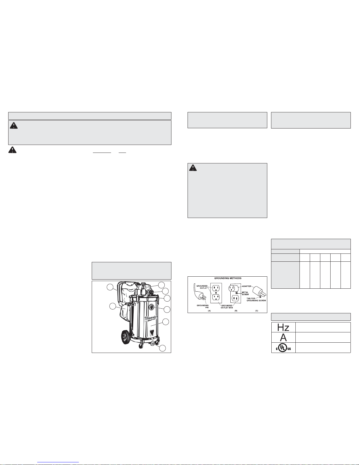
FUNCTIONAL
DESCRIPTION
1. Motor head
handle
2. Exhaust port
3. Tank latch
4. Intake port
5. Tank
6. Drain valve
7. Accessory storage pouch
8. Handle
7
2
1
5
4
3
8
6
Hertz
Amps
Underwriters Laboratories, Inc.
United States and Canada
SYMBOLOGY
Page 3
4
5
Cat. No.
Volts
AC Amps For Materials
Tank Capacity
Gallons
Air Flow Cubic
Feet per Minute
Sealed Suction
in Water
8911
8912
8925
8926
8945
8965
120
120
120
120
120
120
7.5
9.2
9.2
9.2
9.2
6.2
Wet or Dry
Wet or Dry
Wet or Dry
Wet or Dry
Wet or Dry
Wet or Dry
11
11
15
21
no tank
10
94
92
92
92
92
133
84"
130"
130"
130"
130"
49"
Using the Vacuum Cleaner To Pick Up Wet
Materials:
A fl oat valve shuts off suction
when the tank is full. Be sure
the fl oat is clean and moves
freely in the fl oat cage to ensure
that the fl oat valve works.
Float
cage
Float
SPECIFICATIONS
WARNING To reduce
the risk of injury, always unplug tool before
changing or removing accessories. Only use
accessories specifi cally recommended for
this tool. Others may be hazardous.
OPERATION
WARNING To reduce the
risk of injury, wear safety goggles or glasses
with side shields.
WARNING To reduce the
risk of fi re, electric shock, injury, and damage
to the tool: Do not plug any tool or appliance rated over 5 amps into the outlet on the
vacuum cleaner. Check nameplate on the tool
for the amp rating.
WARNING To reduce the
risk of electric shock, DO NOT pick up wet materials unless the vacuum cleaner is properly
set up to pick up wet materials.
Starting and Stopping Vacuum Cleaner
To turn on the vacuum cleaner, set the ON/OFF
switch to the ON position.
To turn off the vacuum cleaner, set the ON/OFF
switch to the OFF position.
Using the Vacuum Cleaner To Pick Up Dry Materials:
Make sure that the tank is dry before using the
vacuum cleaner to pick up dry materials. If the
vacuum cleaner tank is wet, run the vacuum cleaner
for about 5 minutes (without picking up anything) to
dry the inside of the tank.
4. Attach
cloth fi lter (D) to fi lter frame (D).
5. Set fi
lter frame and cloth fi
lter assembly (C and
D)
onto tank.
6. Replace motor head and snap down tank
latches.
Changing Paper Filter Bag and Cleaning Cloth
Filter
1. Remove motor head and set aside.
2.
Clean the cloth fi lter each time the tank is emptied
by shaking off loose material and brushing the
fi lter with a soft bristle brush. Do not wash cloth
fi lter with water. Washing can shrink the fi lter and
damage the gasket.
3. Pull bag out of the tank using care not the tear bag
on intake tube. Seal bag with cardboard fl aps and
discard.
Using the Vacuum Cleaner To Collect Dust Created By Tools:
Many tools (such as sanders) are designed so they
can be used with vacuum cleaners. The vaccum
cleaners collect the dust that these tools create
before it gets into the air or onto the fl oor. Vacuum
cleaners with the AUTO setting are ideal for collecting
dust because they can be set up to turn on and off
automatically using the tool’s AUTO/ON/OFF switch.
Vacuum cleaners without an AUTO setting can still
collect dust. The operator will simply have to turn the
vacuum on and off.
Using a Vacuum Cleaner without an Automatic
Switch as a Dust Collection Device for a Tool
1. Connect vaccum hose to the tool’s dust collection
port.
2. Turn on the vacuum cleaner.
3. Turn on tool.
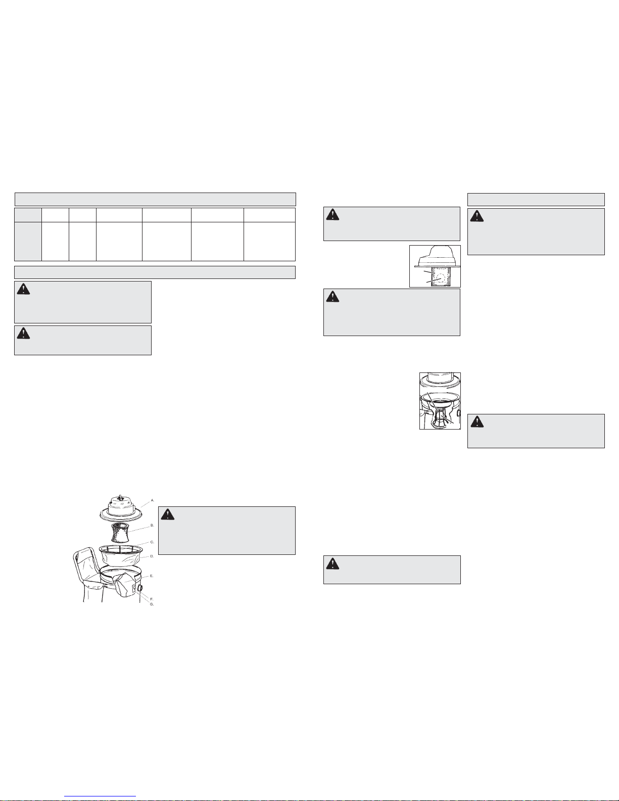
Installing Filters
1.
Remove motor head (A) and set aside.
Caution: Use care when handling motor head.
Dropping motor head may cause permanent
damage.
2.
If you are using Cat. No. 8965, place foam fi lter
sleeve (B) over fl oat value cage.
3.
Install only one of the following fi lters:
If you plan to vacuum dry material into a fi lter bag,
expand the paper fi lter bag
(E) and fi
t cardboard collar
(G) onto the intake tube (F)
as far as possible.
If you plan to vacuum medium fi ne to coarse, sharp
dry material directly into the
tank without a fi lter
bag, fi t a
dacron fi lter onto
the cloth fi lter as-
sembly (C and D).
If you plan to vacuum extremely fi ne
material directly
into the tank without a fi lter bag, fi t
a paper fi lter onto
the tank.
Using a Vacuum Cleaner with an Automatic
Switch as a Dust Collection Device for a Tool
1. Connect vacuum hose to the tool.
2. Plug the tool into the electrical outlet on the
vacuum cleaner’s motor head.
3. Set the AUTO/ON/OFF switch to the AUTO position.
4. Turn on the tool and the vacuum cleaner will start
automatically within a few seconds.
Float cage
Float
Cat. No. 8965 does not need a wet adapter for picking
up wet materials. The safety valve is already built in
to the 8965 vaccum cleaner. Do not remove the foam
fi lter sleeve. It is designed to be used with both wet
and dry materials.
Installing Wet Adapter
1. Remove motorhead and set
aside.
2.
Set wet adapter into tank.
3. Replace motorhead and snap
down tank latches.
Removing Liquid from the Vacuum
Tank on Vacuum Cleaners with
Drain Valves
1. Center drain valve over fl oor drain.
2. Open drain valve.
For Cat. No. 8925, open drain valve by turning the
drain valve handle counter clockwise. To closedrain valve trun clockwise.
For Cat. No. 8924 and 8926, open drain valve by
pulling up on the handle. To close push down on
handle.
3. Drain.
4. Rinse, dry tank and close drain valve.
Removing Liquid from the Vacuum Tank on
Vacuum Cleaners without Drain Valves
1. Remove motorhead and wet adapter and set aside.
2. Block
wheels.
3.
Carefully dump contents into fl oor drain.
4.
Rinse and dry tank.
Do not store vacuum cleaner with liquid in tank. Run
the vacuum for about 5 minutes without picking up
anything to dry the inside of the tank.
WARNING If the fl oat is
clean, moves freely and the suction does not
shut off when the tank is fi lled (you will be
able to see water in the exhaust port), send
the motorhead to the nearest MILWAUKEE
service facility for repair.
Using the Vacuum as a Blower
1. Attached hose exhaust port on the motorhead.
2. Attach the appropriate accessory to the hose.
3. Turn the vacuum on.
W ARNING T o reduce the risk
of injury: wear safety glasses and a dustmask
when using the vacuum cleaner as a blower.
Maintaining Tools
Keep your tool in good repair by adopting a regular
maintenance program. Before use, examine the
general condition of your tool. Inspect guards,
switches, tool cord set and extension cord for
damage. Check for loose screws, misalignment,
binding of moving parts, improper mounting, broken parts and any other condition that may affect
its safe operation. If abnormal noise or vibration
occurs, turn the tool off immediately and have the
problem corrected before further use. Do not use a
damaged tool. T ag damaged tools “DO NOT USE”
until repaired (see “Repairs”).
Under normal conditions, relubrication is not necessary until the motor brushes need to be replaced.
After six months to one year, depending on use,
return your tool to the nearest MILWAUKEE service
facility for the following:
• Lubrication
• Brush inspection and replacement
• Mechanical inspection and cleaning (gears, spindles, bearings, housing, etc.)
• Electrical inspection (switch, cord, armature, etc.)
• Testing to assure proper mechanical and electrical
operation
WARNING To reduce the
risk of injury, electric shock and damage to
the tool, never immerse your tool in liquid or
allow a liquid to fl ow inside the tool.
WARNING To reduce
the risk of injury, always unplug your tool
before performing any maintenance. Never
disassemble the tool or try to do any rewiring on the tool’s electrical system. Contact a
MILWAUKEE service facility for ALL repairs.
Cleaning
Clean dust and debris from vents. Keep the tool
handles clean, dry and free of oil or grease. Use
only mild soap and a damp cloth to clean your
tool since certain cleaning agents and solvents
are harmful to plastics and other insulated parts.
Some of these include: gasoline, turpentine, lacquer
thinner, paint thinner , chlorinated cleaning solvents,
ammonia and household detergents containing
ammonia. Never use fl ammable or combustible
solvents around tools.
Storage
Before storing the vacuum cleaner, always empty
and clean the tank. Never allow debris to sit in
the tank for any extended period of time. The
vacuum cleaner should be stored indoors.
MAINTENANCE
Page 4

Cat. No.
8975
8977
8978
8986-20
8988-20
TO REDUCE THE RISK OF INJURY, USER MUST READ AND UNDERSTAND OPERATOR'S
MANUAL.
OPERATOR'S MANUAL
HEAVY-DUTY HEAT GUNS
Page 5

PERSONAL SAFETY
GENERAL POWER TOOL SAFETY WARNINGS
WORK AREA SAFETY
ELECTRICAL SAFETY
• Keep work area clean and well lit. Cluttered or
dark areas invite accidents.
• Do not operate power tools in explosive atmospheres, such as in the presence of fl ammable
liquids, gases or dust. Power tools create
sparks which may ignite the dust or fumes.
• Keep children and bystanders away while
operating a power tool. Distractions can cause
you to lose control.
• Power tool plugs must match the outlet. Never
modify the plug in any way. Do not use any
adapter plugs with earthed (grounded) power
tools. Unmodifi ed plugs and matching outlets will
reduce risk of electric shock.
• Avoid body contact with earthed or grounded
surfaces such as pipes, radiators, ranges and
refrigerators. There is an increased risk of elec-
tric shock if your body is earthed or grounded.
• Do not expose power tools to rain or wet conditions. W ater entering a power tool will increase
the risk of electric shock.
• Do not abuse the cord. Never use the cord for
carrying, pulling or unplugging the power tool.
Keep cord away from heat, oil, sharp edges
or moving parts. Damaged or entangled cords
increase the risk of electric shock.
• When operating a power tool outdoors, use
an extension cord suitable for outdoor use.
Use of a cord suitable for outdoor use reduces
the risk of electric shock.
• If operating a power tool in a damp location
is unavoidable, use a residual current device
(RCD) protected supply. Use of an RCD reduces
the risk of electric shock.
to power source and/or battery pack, picking
up or carrying the tool. Carrying power tools
with your fi nger on the switch or energising power
tools that have the switch on invites accidents.
• Remove any adjusting key or wrench before
turning the power tool on. A wrench or a key
left attached to a rotating part of the power tool
may result in personal injury.
• Do not overreach. Keep proper footing and
balance at all times. This enables better control
of the power tool in unexpected situations.
• Dress properly. Do not wear loose clothing or
jewellery. Keep your hair , clothing and gloves
away from moving parts. Loose clothes, jewel-
lery or long hair can be caught in moving parts.
• If devices are provided for the connection of
dust extraction and collection facilities, ensure
these are connected and properly used. Use of
dust collection can reduce dust-related hazards.
WARNING READ ALL SAFETY WARNINGS AND INSTRUCTIONS.
Failure to follow the warnings and instructions may result in electric shock, fi re and/or
serious injury. Save all warnings and instructions for future reference
The term "power tool" in the warnings refers to your mains-operated (corded) power tool or
battery-operated (cordless) power tool.
POWER TOOL USE AND CARE
• Do not force the power tool. Use the correct
power tool for your application. The correct
power tool will do the job better and safer at the
rate for which it was designed.
• Do not use the power tool if the switch does
not turn it on and off. Any power tool that cannot
be controlled with the switch is dangerous and
must be repaired.
• Disconnect the plug from the power source
and/or the battery pack from the power tool
before making any adjustments, changing
accessories, or storing power tools. Such
preventive safety measures reduce the risk of
starting the power tool accidentally.
• Store idle power tools out of the reach of children and do not allow persons unfamiliar with
the power tool or these instructions to operate
the power tool. Power tools are dangerous in the
hands of untrained users.
• Maintain power tools. Check for misalignment
or binding of moving parts, breakage of parts
and any other condition that may affect the
power tool’s operation. If damaged, have the
power tool repaired before use. Many accidents
are caused by poorly maintained power tools.
• Keep cutting tools sharp and clean. Properly
maintained cutting tools with sharp cutting edges
are less likely to bind and are easier to control.
• Use the power tool, accessories and tool bits
etc., in accordance with these instructions,
taking into account the working conditions
• Stay alert, watch what you are doing and use
common sense when operating a power tool.
Do not use a power tool while you are tired or
under the infl uence of drugs, alcohol or medi-
cation. A moment of inattention while operating
power tools may result in serious personal injury.
• Use personal protective equipment. Always
wear eye protection. Protective equipment such
as dust mask, non-skid safety shoes, hard hat, or
hearing protection used for appropriate conditions
will reduce personal injuries.
• Prevent unintentional starting. Ensure the
switch is in the off-position before connecting
IMPORT ANT SAFETY INSTRUCTIONS
HEAT GUNS
and the work to be performed. Use of the power
tool for operations different from those intended
could result in a hazardous situation.
SERVICE
• Have your power tool serviced by a qualifi ed
repair person using only identical replacement
parts. This will ensure that the safety of the power
tool is maintained.
READ THESE INSTRUCTIONS
• Know your work environment. Hidden areas
such as behind walls, ceilings, fl oors, soffi t boards
and other panels may contain fl ammable materials
that may ignite when using the heat gun in these
locations. Ignition of these materials may not be
readily apparent and could result in property damage and personal injury. Check these areas before
applying heat. If in doubt, use an alternate method.
Pausing or lingering in one spot may ignite the
panel or the material behind it. Keep heat gun
moving to avoid excessive temperatures.
• Do not direct the heat gun air airfl ow at clothing,
hair or other body parts. Do not use as a hair
dryer. Heat guns can produce 1000°F (540°C) or
more of fl ameless heat at the nozzle. Contact with
the air stream could result in personal injury.
• Do not use near fl ammable liquids or in ex-
plosive atmospheres, such as in the presence
of fumes, gases or dust. The fl ameless heat
from the heat gun may ignite the dust or fumes.
Remove materials or debris that may become
ignited from work area.
• Shield materials around the heated area to
prevent property damage or fi re.
• Keep a fi re extinguisher nearby . Heat guns may
ignite fl ammable materials left in the work area.
• WARNING! Hot Surfaces. Always hold the heat
gun by the plastic enclosure. Do not touch
nozzle, accessory tips or store heat gun until
the nozzle has cooled to room temperature.
The metal nozzle requires approximately 20
minutes to cool before it can be touched. Contact
with the nozzle or accessory tip could result in
personal injury. Place the heat gun in a clear area
away from combustible materials while cooling to
prevent fl ammable materials from igniting.
• Do not cut off airfl ow by placing nozzle too
close to workpiece. Keep intake vents clean
and clear of obstructions. Restricting airfl ow may
cause the heat gun to overheat.
• Place the heat gun on a stable, level surface
when not hand held. Use the support pads or
support stand. Place cord in a position that won’t
cause the heat gun to tip over.
• Do not leave the heat gun unattended while
running or cooling down. Inattention invites
accidents.
PERSONS REMOVING PAINT SHOULD
FOLLOW THESE GUIDELINES:
• Work in a well ventilated area. If possible, move
the workpiece outdoors. If working indoors, open
windows and place an exhaust fan in a window. Be
sure the fan is moving air from inside to outside.
Proper ventilation will reduce the risk of inhaling
chemicals found in the fumes or dust created by
using a heat gun.
• Store indoors in a dry location. Do not expose
to rain or moisture.
• Do not direct airfl ow directly on glass. The
glass may crack and could result in property
damage or personal injury.
• Maintain labels and nameplates. These carry
important information. If unreadable or missing,
contact a MILWAUKEE Service facility for a free
replacement.
• WARNING Some dust created by power sanding,
sawing, grinding, drilling, and other construction
activities contains chemicals known to cause
cancer, birth defects or other reproductive harm.
Some examples of these chemicals are:
• lead from lead-based paint
• crystalline silica from bricks and cement and other
masonry products, and
• arsenic and chromium from chemically-treated
lumber.
Your risk from these exposures varies, depending on how often you do this type of work. To
reduce your exposure to these chemicals:
work in a well ventilated area, and work with
approved safety equipment, such as those dust
masks that are specially designed to fi lter out
microscopic particles.
IMPORT ANT SAFETY INSTRUCTIONS
FOR REMOVING PAINT
WARNING Use extreme care when
stripping paint. Peelings, residue
and vapors of paint may contain lead,
which is POISONOUS. Pre-1977 paint
may contain lead and paint made
before 1950 is likely to contain lead. Hand to
mouth contact with paint peelings or residue
from pre-1977 paint may result in lead
ingestion. Exposure to even low levels of lead
can cause irreversible brain and nervous
system damage. Young and unborn children
are especially vulnerable to lead poisoning.
DO NOT REMOVE LEAD-BASED PAINT WITH
A HEAT GUN. Before beginning your work,
determine whether the paint you are removing
contains lead. A local health department or
a professional who uses a paint analyzer
can check the paint for lead content. LEADBASED PAINT SHOULD BE REMOVED ONL Y
BY A PROFESSIONAL.
Page 6
• Remove or cover any carpets, rugs, furniture,
clothing, cooking utensils and air ducts to pre-
vent property damage from the paint peelings.
• Place drop cloths in the work area to catch paint
scrapings. Wear protective clothing such as
hats, extra work shirts and overalls. Paint scrapings
may contain chemicals that are hazardous.
• Work in one room at a time. Remove furnishings
or cover them and place in the center of the room.
Seal doorways with drop cloths to seal work area
from the rest of the building.
• Children, pregnant or potentially pregnant
women, and nursing mothers should not be
near work area until all work is completed and
work area is cleaned thoroughly.
• Wear a dust respirator mask or a dual fi lter
(dust and fume) respirator mask which has
been approved by the Occupational Safety and
Health Administration (OSHA), the National
Institute of Safety and Health (NIOSH), or the
United States Bureau of Mines. These masks and
replaceable fi lters are readily available at major
hardware stores. Be sure the mask fi ts. Beards
and facial hair may keep masks from sealing properly. Change fi lters often. DISPOSABLE PAPER
MASKS ARE NOT ADEQUATE.
• Use caution when operating the heat gun.
Keep the heat gun moving to prevent excessive
Fig. B
Fig. C
Fig. A
GROUNDING
WARNING Improperly connecting the
grounding wire can result in the risk of
electric shock. Check with a qualifi ed electri-
cian if you are in doubt as to whether the
outlet is properly grounded. Do not modify
the plug provided with the tool. Never remove
the grounding prong from the plug. Do not
use the tool if the cord or plug is damaged. If
damaged, have it repaired by a MILWAUKEE
service facility before use. If the plug will not
fi t the outlet, have a proper outlet installed by
a qualifi ed electrician.
Grounded Tools: Tools with Three Prong Plugs
Tools marked “Grounding Required” have a three
wire cord and three prong grounding plug. The
plug must be connected to a properly grounded
outlet (See Figure A). If the tool should electrically
malfunction or break down, grounding provides a
low resistance path to carry electricity away from
the user, reducing the risk of electric shock.
The grounding prong in the plug is connected
through the green wire inside the cord to the
grounding system in the tool. The green wire in the
cord must be the only wire connected to the tool's
grounding system and must never be attached to
an electrically “live” terminal.
Your tool must be plugged into an appropriate outlet, properly installed and
grounded in accordance with
all codes and ordinances. The
plug and outlet should look like
those in Figure A.
Double Insulated Tools: Tools with Two Prong
Plugs
Tools marked “Double Insulated” do not require
grounding. They have a special double insulation
system which satisfi es OSHA requirements and
complies with the applicable standards of Underwriters Laboratories, Inc.,
the Canadian Standard Association and the National Electrical Code. Double Insulated
tools may be used in either of
the 120 volt outlets shown in
Figures B and C.
* Cubic feet per minute
SPECIFICATIONS
Cat. No. Volts AC Max. Amps Max. Watts Temperature Airfl ow CFM*
8975
8977
8978
8986-20
8988-20
120
120
120
120
120
11.6
11.6
12.5
12.5
12.5
1400
1400
1500
1500
1500
570° F / 1000° F (300°C / 540°C)
140° F / 1040° F (60°C / 560°C)
200° F / 1100° F (93°C / 593°C)
90°F / 1100°F (32°C - 593°C)
90°F / 1100°F (32°C - 593°C)
14.8
14.8
14.8
7-16
7-16
Grounded tools require a three wire extension
cord. Double insulated tools can use either a two
or three wire extension cord. As the distance from
the supply outlet increases, you must use a heavier
gauge extension cord. Using extension cords with
inadequately sized wire causes a serious drop in
voltage, resulting in loss of power and possible tool
damage. Refer to the table shown to determine the
required minimum wire size.
The smaller the gauge number of the wire, the
greater the capacity of the cord. For example, a 14
gauge cord can carry a higher current than a 16
gauge cord. When using more than one extension
cord to make up the total length, be sure each cord
contains at least the minimum wire size required. If
you are using one extension cord for more than one
tool, add the nameplate amperes and use the sum
to determine the required minimum wire size.
READ AND SAVE ALL
INSTRUCTIONS FOR FUTURE USE.
Recommended Minimum Wire Gauge
for Extension Cords*
Extension Cord Length
* Based on limiting the line voltage drop to fi ve volts
at 150% of the rated amperes.
Nameplate
Amperes
0 - 2.0
2.1 - 3.4
3.5 - 5.0
5.1 - 7.0
7.1 - 12.0
12.1 - 16.0
16.1 - 20.0
25'
18
18
18
18
16
14
12
75'
18
18
16
14
12
10
100'
18
16
14
12
10
150'
16
14
12
12
50'
18
18
18
16
14
12
10
EXTENSION CORDS
Guidelines for Using Extension Cords
• If you are using an extension cord outdoors,
be sure it is marked with the suffi x “W-A” (“W”
in Canada) to indicate that it is acceptable for
outdoor use.
• Be sure your extension cord is properly wired
and in good electrical condition. Always replace
a damaged extension cord or have it repaired by
a qualifi ed person before using it.
• Protect your extension cords from sharp objects,
excessive heat and damp or wet areas.
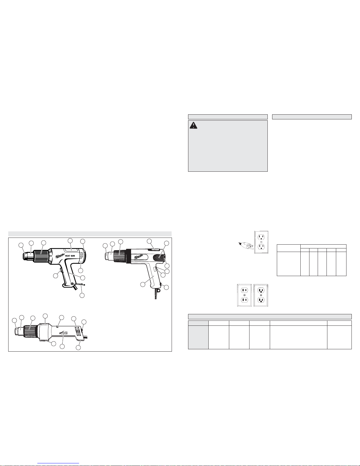
Cat. Nos. 8986-20 and 8988-20
1. Accessory attachment area
2. Nozzle
3. Front cover
4. Temperature display
(Cat. No. 8988-20 only)
5. Support base
6. Temperature control switch
7. Handle
8. Airfl ow control switch / On/off switch
9. Intake vents
Functional Description
Cat. Nos. 8975 and 8977
1. Accessory attachment area
2. Nozzle
3. Front cover
4. Nameplate
5. Intake vents
6. End cap temperature control
(Cat. No. 8977 only)
7. Handle
8. Support stand
9. On/off switch (On/off- high/low on 8975)
Cat. No. 8978
1. Accessory attachment area
2. Nozzle
3. Front cover
4. Nameplate
5. Heat adjustment knob
2
1
3
5
4
6
8
7
9
2
1
3
5
4
6
8
7
9
6. Intake vents
7. On/off switch
8. Handle
9. Support base
9
2
1
3
5
4
6
8
7
9
5
temperatures. Excessive heat can cause paint
and other materials to burn and cause fumes,
which may be inhaled by the operator.
• Keep work environment clean. Keep food and
drink away from work area. Wash hands, arms
and face and rinse mouth before eating and drinking. Do not smoke, or chew gum or tobacco in the
work area. Paint scrapings and dust created from
removing paint may contain chemicals that are
hazardous.
• Clean up all paint scraping and dust. DO NOT
SWEEP, DRY DUST OR VACUUM. Wet mop
fl oors. Use a wet cloth to clean all walls, sills and
other surfaces where paint and dust have accumulated. Use a high phosphate detergent, trisodium phosphate (TSP), or a trisodium phosphate
substitute to clean and mop the work area.
• Dispose of paint scrapings properly. Following
each work session, place paint scrapings in a
double plastic bag, close it with tape or twist ties
and dispose.
• Remove protective clothing and work shoes
in the work area to avoid transferring dust to
other parts of the building. Wash work clothes
separately. Wipe shoes off with a wet rag that is
then washed with the work clothes. Wash hair and
body thoroughly with soap and water.
SAVE THESE INSTRUCTIONS
Page 7
ASSEMBLY
WARNING T o reduce the risk of injury ,
always unplug tool before attaching
or removing accessories or making adjustments. Use only specifi cally recommended
accessories. Others may be hazardous.
WARNING To reduce the risk of
injury, do not remove accessory tips until
tool has cooled to room temperature.
Installing Reduction Nozzles
Reduction nozzles are used to intensify the application of heat in a specifi c area.
For reduction nozzle 49-80-0297:
1. To install the reduction nozzle to the heat gun,
slide the nozzle onto the heat gun nose.
2. Adjust heat, distance and length of application
as necessary.
For reduction nozzles 49-80-0305, 49-80-0306
(For use with electronic controlled heat guns 8978,
8986-20 and 8988-20 only):
1. To install the reduction nozzle to the heat gun,
align the grooves on the nozzle with the grooves
on the heat gun nose.
2. Slide the nozzle onto the nose.
3. Adjust heat, distance and length of application
as necessary.
Installing Slit and Cutting Nozzles
The slit nozzle 49-80-0308 is used for lap welding.
The cutting nozzle 49-80-0309 is used as a heated
cutting edge.
NOTE: The reduction nozzle 49-80-0305 is needed
as an attachment for the slit and cutting nozzles.
(For use with electronic controlled heat guns 8978,
8986-20 and 8988-20 only):
1. To install the reduction nozzle to the heat gun,
align the grooves on the nozzle with the grooves
on the heat gun nose and slide the nozzle onto
the nose.
2. Slide the slit or cutting nozzle onto the reduction
nozzle.
3. Adjust heat, distance and length of application
as necessary.
SYMBOLOGY
Double Insulated Canadian Standards Association
Volts Alternating Current Underwriters Laboratories, Inc.
Amps
Underwriters Laboratories, Inc.
United States and Canada
Watts
OPERATION
WARNING To reduce the risk of injury,
always unplug tool before attaching
or removing accessories or making adjustments. Use only specifi cally recommended
accessories. Others may be hazardous.
WARNING To reduce the risk of injury,
wear safety goggles or glasses with side
shields.
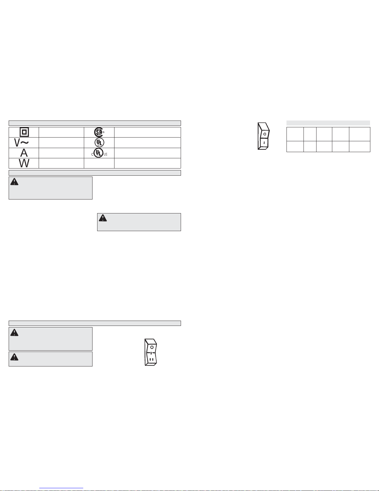
Cat. No. 8977
Variable temperature model heat
guns are marked “O” for OFF and
“l” for ON. Temperature is controlled by turning the end cap in the
directions dictated by the arrows.
Cat. No. 8978
Electronic temperature control system heat guns
allow the tool to produce a greater concentration
of heat at the nozzle, allowing the use of various
accessory nozzles.
The electronic control system regulates the temperature within the tool’s heating element. Unlike
non-electronic heat guns, MILWAUKEE’s electronic
heat gun will maintain the same temperature even
when the air fl ow is decreased or restricted with
the use of accessory nozzles.
Cat. No. 8978 is a variable temperature heat gun
with a range between 200° F and 1100° F (93° C
to 593° C). The heat adjustment knob is a dial with
numbers 1 through 6 on it as shown. The lower
numbers correspond to cooler temperatures and
higher numbers correspond to warmer temperatures. To adjust temperature, simply turn the dial
to the left or the right.
Cat. No. 8986-20 and 8988-20
These heat guns have a variable temperature
control switch, which allows the user to adjust the
temperature for specifi c applications.
The electronic temperature control system regulates the temperature within the tool's heating element. Unlike non-electronic heat guns,
MILWAUKEE's electronic heat gun will maintain the same temperature even when the air
flow is decreased or restricted with the use of
accessory nozzles. Refer to the airfl ow/temperature
chart for various airfl ow and temperature settings.
On Cat. No. 8988-20, a temperature display shows
the heat gun temperature setting.
1. Slide the airfl ow control switch (blue switch)
to Position II or III to operate the temperature
control switch.
2. To adjust the temperature, slide the temperature
control switch (red switch) to the desired position.
When the temperature control switch is set to the
desired position on the 8988-20, the temperature
for that position will show on the temperature
display. After 3 seconds, the temperature display
will show the heat gun’s actual temperature. The
temperature display will continue to show the
actual temperature as the heat gun adjusts to the
desired temperature set by the temperature control
switch position.
O = Off
I = Low Temp.
570° F
I I = High Temp.
1000° F
O = Off
I = On
Airfl ow/Temperature Settings (8986-20 & 8988-20)
Airfl ow
Control
Switch
Setting
Position I
Position II
Position III
Airfl ow
Fan
Speed
High
Low
High
Minimum
Temp.
Setting
90°F
90°F
90°F
Maximum
Temp.
Setting
90°F
1100°F
1100°F
Air Flow at
Maximum
Temp.
Setting
7 CFM*
8.8 CFM
16 CFM
* Cubic feet per minute
Using the Airfl ow Control Switch
(Cat. No. 8986-20 & 8988-20)
Cat. No. 8986-20 & 8988-20 have three airfl ow
settings: high without heat, low with heat and high
with heat. Refer to the airfl ow/temperature chart for
various airfl ow and temperature settings.
1. For high airfl ow without heat, slide the airfl ow
control switch (blue switch) to Position I.
NOTE: The temperature control switch (red
switch) will not operate in this position.
2. For low airfl ow with heat, slide the airfl ow control
switch (blue switch) to Position II. The temperature may be adjusted from 90°F to 1100°F using
the temperature control switch (red switch).
The airfl ow will automatically increase as the
temperature increases.
3. For high airfl ow with heat, slide the airfl ow control
switch (blue switch) to Position III. The temperature may be adjusted from 90°F to 1100°F using
the temperature control switch (red switch).
The airfl ow will automatically increase as the
temperature increases.
4. To turn the heat gun off, slide the airfl ow control
switch (blue switch) to Position 0.
Selecting Temperature
The proper amount of heat for each application depends on the temperature range selected, distance
between the nozzle and workpiece, and the length of
time heat is applied. Experiment with scrap materials
and start with lowest temperature range. Be cautious
when working until the proper combination of heat,
distance and time of application has been obtained.
Use a back and forth motion when applying heat
unless concentrated heat is desirable.
Support Stand (Cat. Nos. 8975 and 8977)
Cat. Nos. 8975 and 8977 have a support stand,
which allows you to position the heat gun upright
on a workbench, leaving both hands free for your
application. When using Cat. Nos. 8975 and 8977
on a workbench, always place tool on a fl at surface
and snap the support stand into the notched position. Place the cord so the heat gun won’t tip. The
rear vent openings are designed to allow air fl ow
even when the tool is resting on the end cap, but
it is important not to cover the vents with foreign
materials such as clothing or rags. Cat. No. 8978
has a fl at bottom surface that acts as a support
stand. Rest the tool on the fl at surface, making sure
to place the cord so the heat gun won’t tip.
Installing Air Directing Nozzles
Air directing nozzles are used to change the direction of the airfl ow.
For hook nozzle 49-80-0292, defl ector 49-80-0293,
air spreader 49-80-0294, soldering refl ector nozzle
49-80-0307:
1. To install an air directing nozzle to the heat gun,
slide the nozzle onto the heat gun nose.
2. Adjust heat, distance and length of application
as necessary.
For air refl ector Cat. No. 49-80-0307 (For use with
electronic controlled heat guns 8978, 8986-20 and
8988-20 only):
1. To install the air refl ector nozzle to the heat gun,
align the grooves on the nozzle with the grooves
on the heat gun nose.
2. Slide the nozzle onto the nose.
3. Adjust heat, distance and length of application
as necessary.
Using the Temperature Control Switch
Cat. No. 8975
Dual temperature control
heat guns have a 3 position rocker switch. Place
the switch in the center
position for “Low” range or
press in the lower position
of the switch completely for
“High” range.
Page 8
APPLICATIONS
WARNING To reduce the risk of heat
damage and personal injury, shield combustible materials and areas adjacent to
workpiece. Protect yourself from hot paint
scrapings and dust.
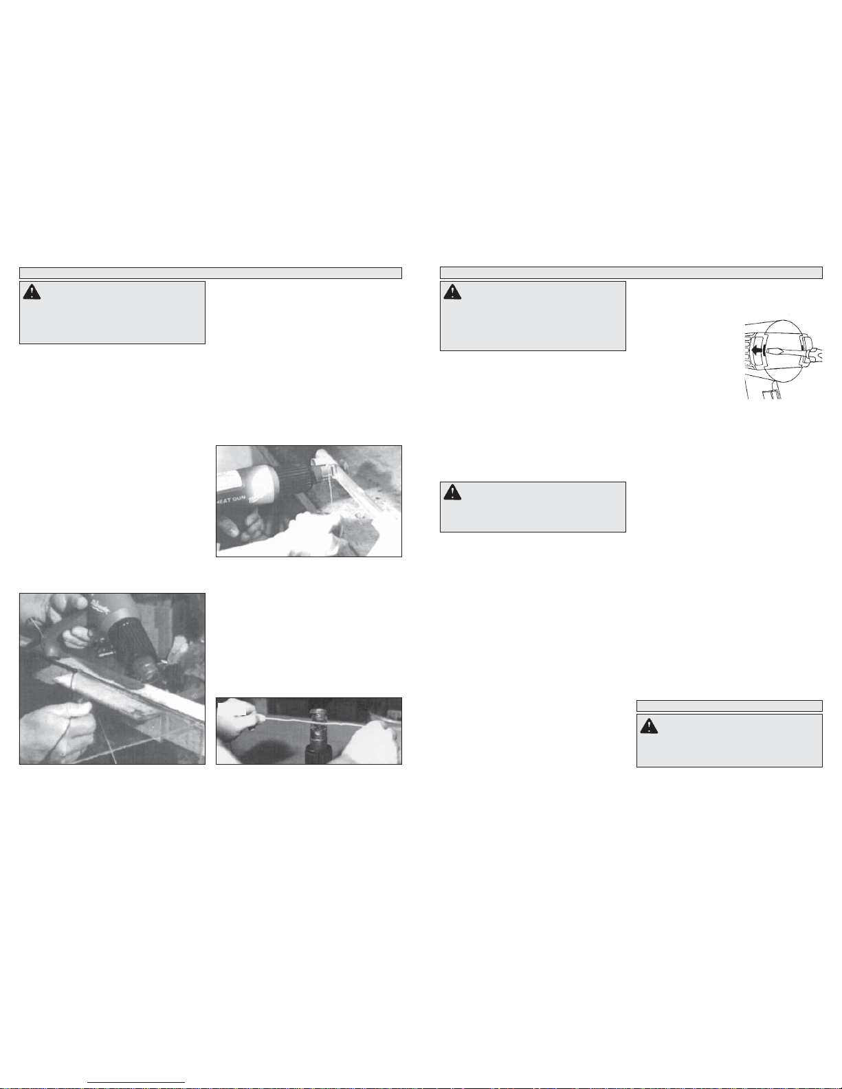
Cutting Styrofoam
1. T o attach the styrofoam cutting nozzle, fi rst attach
reduction nozzle Cat. No. 49-80-0305 to the heat
gun (See “Installing Reduction Nozzles”). Attach
the styrofoam nozzle to the reduction nozzle.
2. To cut styrofoam, use a low to medium temperature setting and apply heat to workpiece in
desired pattern. The nozzle will make straight or
curved cuts and will cut holes or recesses.
NOTE: Slight smoke and odors are normal and
are not harmful as long as you are working with
adequate ventilation. Cut at maximum
speed to avoid excess smoke development and
prevent the nozzle from overheating. Read the
safety instructions supplied with the
material you are cutting.
Soldering
Removing Paint
Read safety instructions for removing paint before
proceeding with paint removal.
1. Begin work with low temperature setting.
2. Place nozzle approximately 1" away from work
surface.
3. Pass nozzle back and forth over a small area of
workpiece.
4. Gradually increase heat until paint starts to
blister, then remove heat.
5. Remove paint using a sharp-edged putty knife.
Creating Bends
Both variable temperature and dual temperature
heat guns are ideal for creating bends in plexiglass
that is used for guards and fi xtures.
1. To form a bend, use either a low or high temperature setting. When using a low temperature, hold
the heat gun close to the workpiece and pass the
nozzle back and forth slowly. When using a high
temperature, hold the heat gun further away
from the workpiece and pass the nozzle back
and forth rapidly.
2. Pass the nozzle over entire length of the surface
to be bent. Applying heat to only part of the
surface will make bending uneven.
Fig. 1
MAINTENANCE
WARNING T o reduce the risk of injury ,
always unplug your tool before performing any maintenance. Never disassemble the tool or try to do any rewiring on
the tool’s electrical system. Contact a
MILWAUKEE service facility for ALL repairs.
Maintaining Tools
Keep your tool in good repair by adopting a regular
maintenance program. Before use, examine the
general condition of your tool. Inspect guards,
switches, tool cord set and extension cord for
damage. Check for loose screws, misalignment,
binding of moving parts, improper mounting, broken parts and any other condition that may affect
its safe operation. If abnormal noise or vibration
occurs, turn the tool off immediately and have the
problem corrected before further use. Do not use a
damaged tool. T ag damaged tools “DO NOT USE”
until repaired (see “Repairs”).
WARNING T o reduce the risk of injury ,
electric shock and damage to the tool, never
immerse your tool in liquid or allow a liquid
to fl ow inside the tool.
Cleaning
Clean dust and debris from vents. Keep the tool
handles clean, dry and free of oil or grease. Use
only mild soap and a damp cloth to clean your tool
since certain cleaning agents and solvents are
harmful to plastics and other insulated parts. Some
of these include: gasoline, turpentine, lacquer thinner, paint thinner, chlorinated cleaning solvents,
ammonia and household detergents containing
ammonia. Never use fl ammable or combustible
solvents around tools.
Repairs
If your tool is damaged, return the entire tool to the
nearest service center.
ACCESSORIES
WARNING T o reduce the risk of injury ,
always unplug the tool before attaching
or removing accessories. Use only specifi -
cally recommended accessories. Others may
be hazardous.
1. Attach the soldering refl ector nozzle or hook
nozzle to the heat gun.
2. Deburr the pipe and joint using sandpaper or
steel wool.
3. T o solder with either lead or non-lead solder, coat
the tip on both the copper pipe and the joint with
fl ux. Then slip the joint over the pipe.
4. Slip the accessory nozzle around the joint. With
the heat gun at a high temperature setting, apply
heat to the joint.
5. When the fl ux bubbles, add solder and position
heat gun so excess solder does not drip into the
heat gun.
Heat Shrinking
Fig. 2
Fig. 3
1. Attach the soldering refl ector nozzle or hook
nozzle to the heat gun.
2. To heat shrink tubing, use a low temperature
setting. Apply heat to the workpiece using a side
to side motion until tubing has shrunk. Remove
heat immediately.
Cleaning Air Filters
Cat. No. 8986-20 and 8988-20 only
The air fi lters on these heat guns may be removed
for cleaning.
1. Unplug tool.
2. To remove the air fi lter, in-
sert a fl at screwdriver be-
tween the motor housing
and air fi lter and loosen
the air fi lter off of the back
of the tool.
3. Slide the air fi lter off the
back of the tool.
4. Remove the support pad from the air fi lter using
the screwdriver.
5. Clean any dust or debris off the air fi lter using
warm water and a brush.
NOTE: Allow the air fi lter to dry before reinstall-
ing.
6. To reinstall the air fi lter, slide the air fi lter onto
the intake vent grooves from the back end of the
tool. Allow the air fi lter to snap back into place.
Page 9
Cat. No.
8975-6
8977-20
TO REDUCE THE RISK OF INJURY, USER MUST READ AND UNDERSTAND OPERATOR'S
MANUAL.
OPERATOR'S MANUAL
HEAT GUNS
Page 10

IMPORT ANT SAFETY INSTRUCTIONS
HEAT GUNS
READ THESE INSTRUCTIONS
• Know your work environment. Hidden areas such
as behind walls, ceilings, fl oors, soffi t boards and
other panels may contain fl ammable materials that
may ignite when using the heat gun in these locations. Ignition of these materials may not be readily
apparent and could result in property damage and
personal injury. Check these areas before applying
heat. If in doubt, use an alternate method. Pausing
or lingering in one spot may ignite the panel or the
material behind it. Keep heat gun moving to avoid
excessive temperatures.
• Do not direct the heat gun air airfl ow at clothing,
hair or other body parts. Do not use as a hair
dryer. Heat guns can produce 1100°F (593°C) or
more of fl ameless heat at the nozzle. Contact with
the air stream could result in personal injury.
• Do not use near fl ammable liquids or in explosive
atmospheres, such as in the presence of fumes,
gases or dust. The fl ameless heat from the heat
gun may ignite the dust or fumes. Remove materials
or debris that may become ignited from work area.
• Shield materials around the heated area to prevent property damage or fi re.
• Keep a fi re extinguisher nearby. Heat guns may
ignite fl ammable materials left in the work area.
• WARNING! Hot Surfaces. Always hold the heat
gun by the plastic enclosure. Do not touch
nozzle, accessory tips or store heat gun until
the nozzle has cooled to room temperature. The
metal nozzle requires approximately 20 minutes
to cool before it can be touched. Contact with the
nozzle or accessory tip could result in personal
injury. Place the heat gun in a clear area away from
combustible materials while cooling to prevent fl am-
mable materials from igniting.
• Do not cut off airfl ow by placing nozzle too close
to workpiece. Keep intake vents clean and clear of
obstructions. Restricting airfl ow may cause the heat
gun to overheat.
• Place the heat gun on a stable, level surface
when not hand held. Use the support pads or
support stand. Place cord in a position that won’t
cause the heat gun to tip over.
• Do not leave the heat gun unattended while running or cooling down. Inattention invites accidents.
• Store indoors in a dry location. Do not expose to
rain or moisture.
• Do not direct airfl ow directly on glass. The glass
may crack and could result in property damage or
personal injury.
• Maintain labels and nameplates. These carry
important information. If unreadable or missing,
contact a MILWAUKEE Service facility for a free
replacement.
• WARNING Some dust created by power sanding,
sawing, grinding, drilling, and other construction
activities contains chemicals known to cause cancer, birth defects or other reproductive harm. Some
examples of these chemicals are:
• lead from lead-based paint
• crystalline silica from bricks and cement and other
PERSONS REMOVING PAINT SHOULD
FOLLOW THESE GUIDELINES:
• Work in a well ventilated area. If possible, move the
workpiece outdoors. If working indoors, open windows
and place an exhaust fan in a window. Be sure the fan
is moving air from inside to outside. Proper ventilation
will reduce the risk of inhaling chemicals found in the
fumes or dust created by using a heat gun.
• Remove or cover any carpets, rugs, furniture,
clothing, cooking utensils and air ducts to prevent
property damage from the paint peelings.
• Place drop cloths in the work area to catch paint
scrapings. Wear protective clothing such as hats,
extra work shirts and overalls. Paint scrapings may
contain chemicals that are hazardous.
• Work in one room at a time. Remove furnishings
or cover them and place in the center of the room.
Seal doorways with drop cloths to seal work area
from the rest of the building.
• Children, pregnant or potentially pregnant
women, and nursing mothers should not be near
work area until all work is completed and work area
is cleaned thoroughly.
• Wear a dust respirator mask or a dual filter
(dust and fume) respirator mask which has been
approved by the Occupational Safety and Health Administration (OSHA), the National Institute of Safety
and Health (NIOSH), or the United States Bureau
of Mines. These masks and replaceable fi lters are
readily available at major hardware stores. Be sure
the mask fi ts. Beards and facial hair may keep masks
from sealing properly. Change fi lters often. DISPOS-
ABLE PAPER MASKS ARE NOT ADEQUATE.
masonry products, and
• arsenic and chromium from chemically-treated lumber.
Your risk from these exposures varies, depending
on how often you do this type of work. To reduce
your exposure to these chemicals: work in a well
ventilated area, and work with approved safety
equipment, such as those dust masks that are specially designed to fi lter out microscopic particles.
IMPORT ANT SAFETY INSTRUCTIONS
FOR REMOVING PAINT
WARNING Use extreme care when
stripping paint. Peelings, residue and vapors of
paint may contain lead, which is POISONOUS.
Pre-1977 paint may contain lead and paint
made before 1950 is likely to contain lead.
Hand to mouth contact with paint peelings or
residue from pre-1977 paint may result in lead
ingestion. Exposure to even low levels of lead
can cause irreversible brain and nervous
system damage. Young and unborn children are
especially vulnerable to lead poisoning. DO NOT
REMOVE LEAD-BASED PAINT WITH A HEAT
GUN. Before beginning your work, determine
whether the paint you are removing contains
lead. A local health department or a professional
who uses a paint analyzer can check the paint for
lead content. LEAD-BASED PAINT SHOULD BE
REMOVED ONLY BY A PROFESSIONAL.
PERSONAL SAFETY
GENERAL POWER TOOL SAFETY WARNINGS
WORK AREA SAFETY
ELECTRICAL SAFETY
• Keep work area clean and well lit. Cluttered or
dark areas invite accidents.
• Do not operate power tools in explosive atmospheres, such as in the presence of fl ammable
liquids, gases or dust. Power tools create sparks
which may ignite the dust or fumes.
• Keep children and bystanders away while
operating a power tool. Distractions can cause
you to lose control.
• Power tool plugs must match the outlet. Never
modify the plug in any way. Do not use any
adapter plugs with earthed (grounded) power
tools. Unmodifi ed plugs and matching outlets will
reduce risk of electric shock.
• Avoid body contact with earthed or grounded
surfaces such as pipes, radiators, ranges and
refrigerators. There is an increased risk of electric
shock if your body is earthed or grounded.
• Do not expose power tools to rain or wet conditions. Water entering a power tool will increase
the risk of electric shock.
• Do not abuse the cord. Never use the cord for
carrying, pulling or unplugging the power tool.
Keep cord away from heat, oil, sharp edges
or moving parts. Damaged or entangled cords
increase the risk of electric shock.
• When operating a power tool outdoors, use an
extension cord suitable for outdoor use. Use
of a cord suitable for outdoor use reduces the risk
of electric shock.
• If operating a power tool in a damp location
is unavoidable, use a residual current device
(RCD) protected supply. Use of an RCD reduces
the risk of electric shock.
• Remove any adjusting key or wrench before
turning the power tool on. A wrench or a key left
attached to a rotating part of the power tool may
result in personal injury.
• Do not overreach. Keep proper footing and
balance at all times. This enables better control
of the power tool in unexpected situations.
• Dress properly. Do not wear loose clothing or
jewellery. Keep your hair, clothing and gloves
away from moving parts. Loose clothes, jewel-
lery or long hair can be caught in moving parts.
• If devices are provided for the connection of
dust extraction and collection facilities, ensure
these are connected and properly used. Use of
dust collection can reduce dust-related hazards.
POWER TOOL USE AND CARE
• Do not force the power tool. Use the correct
power tool for your application. The correct
power tool will do the job better and safer at the
rate for which it was designed.
• Do not use the power tool if the switch does not
turn it on and off. Any power tool that cannot be
controlled with the switch is dangerous and must
be repaired.
• Disconnect the plug from the power source
and/or the battery pack from the power tool
before making any adjustments, changing
accessories, or storing power tools. Such pre-
ventive safety measures reduce the risk of starting
the power tool accidentally.
• Store idle power tools out of the reach of children and do not allow persons unfamiliar with
the power tool or these instructions to operate
the power tool. Power tools are dangerous in the
hands of untrained users.
• Maintain power tools. Check for misalignment
or binding of moving parts, breakage of parts
and any other condition that may affect the
power tool’s operation. If damaged, have the
power tool repaired before use. Many accidents
are caused by poorly maintained power tools.
• Keep cutting tools sharp and clean. Properly
maintained cutting tools with sharp cutting edges
are less likely to bind and are easier to control.
• Use the power tool, accessories and tool bits
etc., in accordance with these instructions,
taking into account the working conditions and
the work to be performed. Use of the power tool
for operations different from those intended could
result in a hazardous situation.
• Stay alert, watch what you are doing and use
common sense when operating a power tool. Do
not use a power tool while you are tired or under
the infl uence of drugs, alcohol or medication. A
moment of inattention while operating power tools
may result in serious personal injury.
• Use personal protective equipment. Always
wear eye protection. Protective equipment such
as dust mask, non-skid safety shoes, hard hat, or
hearing protection used for appropriate conditions
will reduce personal injuries.
• Prevent unintentional starting. Ensure the
switch is in the off-position before connecting
to power source and/or battery pack, picking
up or carrying the tool. Carrying power tools with
your fi nger on the switch or energising power tools
that have the switch on invites accidents.
SERVICE
• Have your power tool serviced by a qualifi ed
repair person using only identical replacement
parts. This will ensure that the safety of the power
tool is maintained.
WARNING READ ALL SAFETY WARNINGS AND ALL INSTRUCTIONS. Failure to
follow the warnings and instructions may result in electric shock, fi re and/or serious injury. Save
all warnings and instructions for future reference. The term “power tool” in the warn-
ings refers to your mains-operated (corded) power tool or battery-operated (cordless) power tool.
Page 11
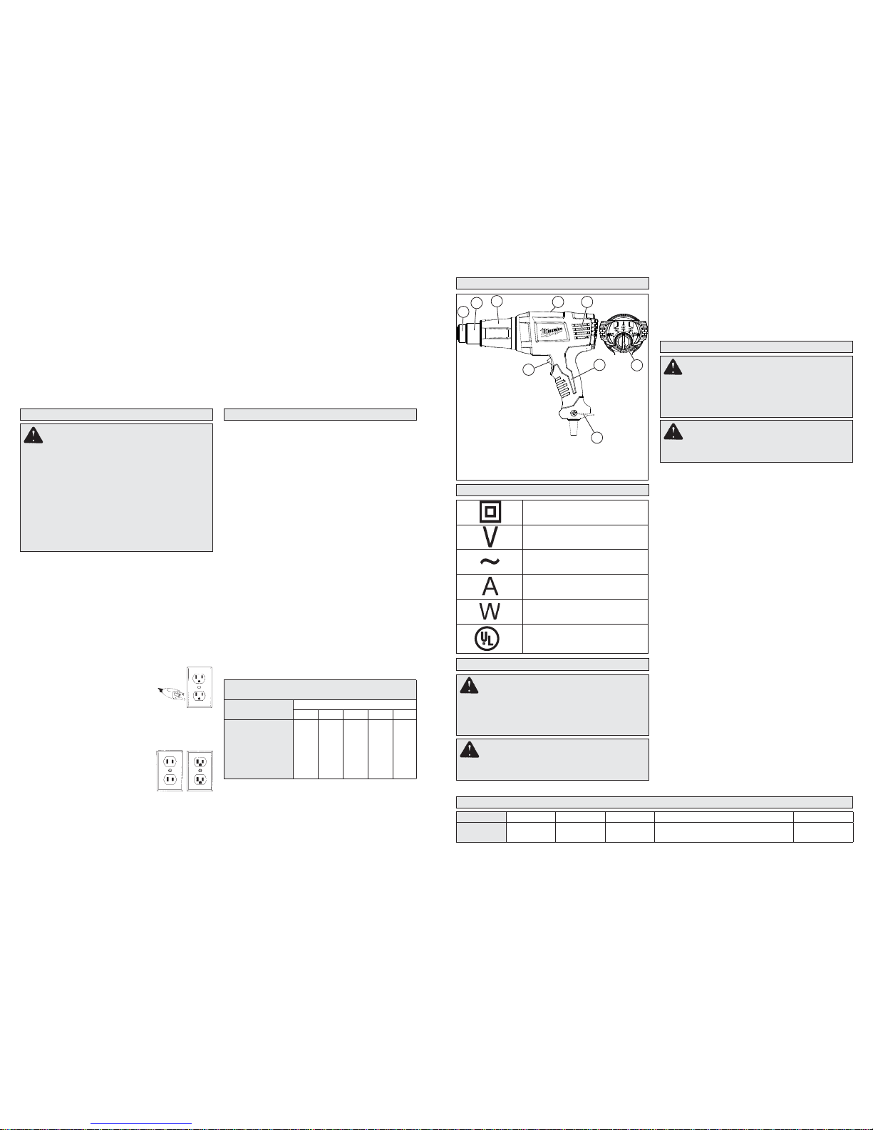
1. Accessory
attachment area
2. Nozzle
3. Front cover
4. Nameplate (on back)
5. Intake vents
6. Handle
7. Support stand
8. High/Low switch (8975-6)
Heat/Cool-down mode switch (8977-20)
9. Variable temperature dial
(8977-20 only)
Grounded Tools: Tools with Three Prong Plugs
Tools marked “Grounding Required” have a three
wire cord and three prong grounding plug. The plug
must be connected to a properly grounded outlet (See
Figure A). If the tool should electrically malfunction
or break down, grounding provides a low resistance
path to carry electricity away from the user, reducing
the risk of electric shock.
The grounding prong in the plug is connected through
the green wire inside the cord to the grounding system
in the tool. The green wire in the cord must be the
only wire connected to the tool's grounding system
and must never be attached to an electrically
“live” terminal.
Your tool must be plugged into an
appropriate outlet, properly installed
and grounded in accordance with
all codes and ordinances. The plug
and outlet should look like those in
Figure A.
Double Insulated Tools: T ools with Two Prong Plugs
Tools marked “Double Insulated”
do not require grounding. They
have a special double insulation
system which satisfies OSHA requirements and complies with the
applicable standards of Underwriters Laboratories, Inc., the Canadian
Standard Association and the National Electrical Code. Double Insulated tools may
be used in either of the 120 volt outlets shown in
Figures B and C.
Grounded tools require a three wire extension cord.
Double insulated tools can use either a two or three
wire extension cord. As the distance from the supply
outlet increases, you must use a heavier gauge extension cord. Using extension cords with inadequately
sized wire causes a serious drop in voltage, resulting
in loss of power and possible tool damage. Refer to
the table shown to determine the required minimum
wire size.
The smaller the gauge number of the wire, the greater
the capacity of the cord. For example, a 14 gauge
cord can carry a higher current than a 16 gauge cord.
When using more than one extension cord to make
up the total length, be sure each cord contains at
least the minimum wire size required. If you are using
one extension cord for more than one tool, add the
nameplate amperes and use the sum to determine
the required minimum wire size.
Guidelines for Using Extension Cords
• If you are using an extension cord outdoors, be sure
it is marked with the suffi x “W-A” (“W” in Canada) to
indicate that it is acceptable for outdoor use.
• Be sure your extension cord is properly wired and in
good electrical condition. Always replace a damaged
extension cord or have it repaired by a qualifi ed
person before using it.
•
Protect your extension cords from sharp objects,
excessive heat and damp or wet areas.
• Use caution when operating the heat gun. Keep
the heat gun moving to prevent excessive temperatures.
Excessive heat can cause paint and other
materials to burn and cause fumes, which may be
inhaled by the operator.
• Keep work environment clean. Keep food and
drink away from work area. Wash hands, arms and
face and rinse mouth before eating and drinking. Do
not smoke, or chew gum or tobacco in the work area.
Paint scrapings and dust created from removing
paint may contain chemicals that are hazardous.
• Clean up all paint scraping and dust. DO NOT
SWEEP , DR
Y DUST OR VACUUM. W et mop fl oors.
Use a wet cloth to clean all walls, sills and other sur-
Fig. B
Fig. C
GROUNDING
SPECIFICATIONS
* Cubic feet per minute
Cat. No. Volts AC Max. Amps Max. Watts Temperature Airfl ow CFM*
8975-6
8977-20
120
120
11.6
11.6
1400
1400
570° F / 1000° F (300°C / 540°C)
100° F / 1040° F (38°C / 560°C)
15
20
READ AND SAVE ALL
INSTRUCTIONS FOR FUTURE USE.
* Based on limiting the line voltage drop to fi ve volts at
150% of the rated amperes.
EXTENSION CORDS
FUNCTIONAL DESCRIPTION
SYMBOLOGY
faces where paint and dust have accumulated. Use
a high phosphate detergent, trisodium phosphate
(TSP), or a trisodium phosphate substitute to clean
and mop the work area.
• Dispose of paint scrapings properly. Following
each work session, place paint scrapings in a double
plastic bag, close it with tape or twist ties and dispose.
• Remove protective clothing and work shoes
in the work area to avoid transferring dust to
other parts of the building. Wash work clothes
separately. Wipe shoes off with a wet rag that is then
washed with the work clothes. Wash hair and body
thoroughly with soap and water.
SAVE THESE INSTRUCTIONS
ASSEMBLY
Installing/Removing Nozzles
1. To install, slide the nozzle onto the heat gun
nose.
2. Adjust heat, distance and length of application
as necessary.
3. To remove, allow tool to cool to room temperature, then pull nozzle away from tool.
2
1
3
6
8
5
4
OPERATION
Selecting Temperature
The proper amount of heat for each application
depends on the temperature selected, distance
between the nozzle and workpiece, and the length
of time heat is applied. Experiment with scrap
materials and start with the lowest temperature.
Be cautious when working until the proper combination of heat, distance and time of application
has been obtained. Use a back and forth motion
when applying heat unless concentrated heat is
desirable. When done, place the tool upright on a
fl at surface, snap the support stand into the center
notched position, and place the cord so the heat
gun won’t tip to allow the nozzle to cool.
High/Low Switch (Cat. No 8975-6)
1. For Low Temperature (570°F), move the switch
to the middle position.
2. For High Temperature (1000°F), press in the
bottom of the switch.
3. For OFF, press in the top of the switch.
Variable Temperature Dial (Cat. No. 8977-20)
1. For ON, push the switch to the (II) position.
2. Rotate the variable temperature dial to increase
or decrease the temperature (up to 1040°F)
3. To cool the tool before storage, push the switch
to the (I) position.
4. For OFF, push the switch to the (0) position.
Hands-Free Use
The heat guns can be positioned upright on a
stable surface, leaving both hands free for the application. Always place tool on a fl at surface, snap
the support stand into the center notched position,
and place the cord so the heat gun won’t tip. The
rear vent openings are designed to allow air fl ow
7
WARNING Improperly connecting the
grounding wire can result in the risk of electric
shock. Check with a qualifi ed electrician if you
are in doubt as to whether the outlet is properly
grounded. Do not modify the plug provided
with the tool. Never remove the grounding
prong from the plug. Do not use the tool if the
cord or plug is damaged. If damaged, have
it repaired by a MILWAUKEE service facility
before use. If the plug will not fi t the outlet,
have a proper outlet installed by a qualifi ed
electrician.
WARNING To reduce the risk of injury,
do not remove or attach accessory tips until
tool has cooled to room temperature.
WARNING To reduce the risk of injury,
always unplug tool before attaching or removing accessories or making adjustments. Use
only specifi cally recommended accessories.
Others may be hazardous.
WARNING To reduce the risk of in-
jury, wear safety goggles or glasses with side
shields.
WARNING To reduce the risk of injury,
always unplug tool before attaching or removing accessories or making adjustments. Use
only specifi cally recommended accessories.
Others may be hazardous.
Fig. A
9
Recommended Minimum Wire Gauge
For Extension Cords*
Nameplate Amps
Extension Cord Length
25' 50' 75' 100' 150'
0 - 2.0
2.1 - 3.4
3.5 - 5.0
5.1 - 7.0
7.1 - 12.0
12.1 - 16.0
16.1 - 20.0
18
18
18
18
16
14
12
18
18
18
16
14
12
10
18
18
16
14
12
10
--
18
16
14
12
10
--
--
16
14
12
12
--
--
--
Double Insulated
Volts
Alternating Current
Amps
Watts
C
US
Underwriters Laboratories, Inc.
United States and Canada
Page 12
APPLICATIONS
MAINTENANCE
Maintaining Tools
Keep your tool in good repair by adopting a regular
maintenance program. Before use, examine the
general condition of your tool. Inspect guards,
switches, tool cord set and extension cord for
damage. Check for loose screws, misalignment,
binding of moving parts, improper mounting, broken parts and any other condition that may affect
its safe operation. If abnormal noise or vibration
occurs, turn the tool off immediately and have the
problem corrected before further use. Do not use a
damaged tool. T ag damaged tools “DO NOT USE”
until repaired (see “Repairs”).
Cleaning
Clean dust and debris from vents. Keep the tool
handles clean, dry and free of oil or grease. Use
only mild soap and a damp cloth to clean your tool
since certain cleaning agents and solvents are
harmful to plastics and other insulated parts. Some
of these include: gasoline, turpentine, lacquer thinner, paint thinner, chlorinated cleaning solvents,
ammonia and household detergents containing
ammonia. Never use fl ammable or combustible
solvents around tools.
Repairs
If your tool is damaged, return the entire tool to the
nearest service center.
ACCESSORIES
Types of Nozzles
•
Hook Nozzle - Surrounding heat for thin pipe weld-
ing, soft soldering copper pipes, tube shaping and
shrinking of shrink tubes.
• Air Reduction Nozzle - Intensifi ed, spot directed
heat for corners, plexiglas bending and soldering.
• Defl ector Nozzle - Defl ected heat protects glass
window panes when removing paint and putty.
• Air Spreader Nozzle - Directs heat over large
areas for drying, removing paint, fl oor coverings,
and vinyl tops.
Removing Paint
Read safety instructions for removing paint before
proceeding with paint removal.
1. Begin work with low temperature setting.
2. Place nozzle approximately 1" away from work
surface.
3. Pass nozzle back and forth over a small area of
workpiece.
4. Gradually increase heat until paint starts to
blister, then remove heat.
5. Remove paint using a sharp-edged putty knife.
Creating Bends
Both variable temperature and dual temperature
heat guns are ideal for creating bends in plexiglas
that is used for guards and fi xtures.
1. To form a bend, use either a low or high tempera-
ture setting. When using a low temperature, hold
the heat gun close to the workpiece and pass the
nozzle back and forth slowly. When using a high
temperature, hold the heat gun further away
from the workpiece and pass the nozzle back
and forth rapidly.
2. Pass the nozzle over entire length of the surface
to be bent. Applying heat to only part of the
surface will make bending uneven.
Soldering
1. Attach the air reduction or hook nozzle to the
heat gun.
2. De-burr the pipe and joint using sandpaper or
steel wool.
3. T o solder with either lead or non-lead solder, coat
the tip on both the copper pipe and the joint with
fl ux. Then slip the joint over the pipe.
4. Slip the accessory nozzle around the joint. With
the heat gun at a high temperature setting, apply
heat to the joint.
5. When the fl ux bubbles, add solder and position
heat gun so excess solder does not drip into the
heat gun.
WARNING To reduce the risk of injury,
electric shock and damage to the tool, never
immerse your tool in liquid or allow a liquid to
fl ow inside the tool.
WARNING To reduce the risk of
injury, always unplug your tool before performing any maintenance. Never disassemble the tool or try to do any rewiring
on the tool’s electrical system. Contact a
MILW AUKEE service facility for ALL repairs.
WARNING To reduce the risk of heat
damage and personal injury, shield combustible materials and areas adjacent to workpiece.
Protect yourself from hot paint scrapings and
dust.
WARNING To reduce the risk of injury,
always unplug the tool before attaching or
removing accessories. Use only specifi cally
recommended accessories. Others may be
hazardous.
Heat Shrinking
1. Attach the air reduction or hook nozzle to the
heat gun.
2. To heat shrink tubing, use a low temperature
setting. Apply heat to the workpiece using a side
to side motion until tubing has shrunk. Remove
heat immediately.
even when the tool is resting on the end cap. Do
not cover the vents with foreign materials such as
clothing or rags.
Page 13
Cat. No.
8988-20
TO REDUCE THE RISK OF INJURY, USER MUST READ AND UNDERSTAND OPERATOR'S
MANUAL.
OPERATOR'S MANUAL
VARIABLE TEMP. HEAT GUN
Page 14

IMPORT ANT SAFETY INSTRUCTIONS
HEAT GUNS
ignite the panel or the material behind it. Keep heat
gun moving to avoid excessive temperatures.
• Do not direct the heat gun air airfl ow at clothing,
hair or other body parts. Do not use as a hair dryer.
Heat guns can produce 1150°F (621°C) or more of
fl ameless heat at the nozzle. Contact with the air
stream could result in personal injury.
• Do not use near fl ammable liquids or in explosive
atmospheres, such as in the presence of fumes,
gases or dust. The fl ameless heat from the heat gun
may ignite the dust or fumes. Remove materials or
debris that may become ignited from work area.
• Shield materials around the heated area to prevent
property damage or fi re.
• Keep a fi re extinguisher nearby. Heat guns may
ignite fl ammable materials left in the work area.
• WARNING! Hot Surfaces. Always hold the heat
gun by the plastic enclosure. Do not touch nozzle,
accessory tips or store heat gun until the nozzle
has cooled to room temperature. The metal nozzle
requires approximately 20 minutes to cool before it
can be touched. Contact with the nozzle or accessory
tip could result in personal injury. Place the heat gun
in a clear area away from combustible materials while
cooling to prevent fl ammable materials from igniting.
• Do not cut off airfl ow by placing nozzle too close
to workpiece. Keep intake vents clean and clear of
obstructions. Restricting airfl ow may cause the heat
gun to overheat.
• Work in one room at a time. Remove furnishings
or cover them and place in the center of the room.
Seal doorways with drop cloths to seal work area
from the rest of the building.
• Children, pregnant or potentially pregnant
women, and nursing mothers should not be near
work area until all work is completed and work area
is cleaned thoroughly.
• Wear a dust respirator mask or a dual filter
(dust and fume) respirator mask which has been
approved by the Occupational Safety and Health Administration (OSHA), the National Institute of Safety
and Health (NIOSH), or the United States Bureau
of Mines. These masks and replaceable fi lters are
readily available at major hardware stores. Be sure
the mask fi ts. Beards and facial hair may keep masks
from sealing properly. Change fi lters often. DISPOS-
ABLE PAPER MASKS ARE NOT ADEQUATE.
• Use caution when operating the heat gun. Keep
the heat gun moving to prevent excessive temperatures. Excessive heat can cause paint and other
materials to burn and cause fumes, which may be
inhaled by the operator.
• Keep work environment clean. Keep food and
drink away from work area. Wash hands, arms and
face and rinse mouth before eating and drinking. Do
not smoke, or chew gum or tobacco in the work area.
Paint scrapings and dust created from removing
paint may contain chemicals that are hazardous.
• Clean up all paint scraping and dust. DO NOT
SWEEP , DRY DUST OR V ACUUM. Wet mop fl oors.
Use a wet cloth to clean all walls, sills and other surfaces where paint and dust have accumulated. Use
a high phosphate detergent, trisodium phosphate
(TSP), or a trisodium phosphate substitute to clean
and mop the work area.
• Dispose of paint scrapings properly. Following
IMPORT ANT SAFETY INSTRUCTIONS FOR REMOVING PAINT
WARNING Use extreme care when
stripping paint. Peelings, residue and vapors of
paint may contain lead, which is POISONOUS.
Pre-1977 paint may contain lead and paint
made before 1950 is likely to contain lead.
Hand to mouth contact with paint peelings or
residue from pre-1977 paint may result in lead
ingestion. Exposure to even low levels of lead
can cause irreversible brain and nervous
system damage. Young and unborn children are
especially vulnerable to lead poisoning. DO NOT
REMOVE LEAD-BASED PAINT WITH A HEAT
GUN. Before beginning your work, determine
whether the paint you are removing contains
lead. A local health department or a professional
who uses a paint analyzer can check the paint
for lead content. LEAD-BASED PAINT SHOULD
BE REMOVED ONLY BY A PROFESSIONAL.
PERSONAL SAFETY
GENERAL POWER TOOL SAFETY WARNINGS
WORK AREA SAFETY
ELECTRICAL SAFETY
• Keep work area clean and well lit. Cluttered or dark
areas invite accidents.
• Do not operate power tools in explosive atmospheres, such as in the presence of fl ammable
liquids, gases or dust. Power tools create sparks
which may ignite the dust or fumes.
• Keep children and bystanders away while operating a power tool. Distractions can cause you to lose
control.
• Power tool plugs must match the outlet. Never
modify the plug in any way. Do not use any adapter
plugs with earthed (grounded) power tools. Un-
modifi ed plugs and matching outlets will reduce risk
of electric shock.
• Avoid body contact with earthed or grounded
surfaces such as pipes, radiators, ranges and
refrigerators. There is an increased risk of electric
shock if your body is earthed or grounded.
• Do not expose power tools to rain or wet conditions. Water entering a power tool will increase the
risk of electric shock.
• Do not abuse the cord. Never use the cord for carrying, pulling or unplugging the power tool. Keep
cord away from heat, oil, sharp edges or moving
parts. Damaged or entangled cords increase the risk
of electric shock.
• When operating a power tool outdoors, use an
extension cord suitable for outdoor use. Use of a
cord suitable for outdoor use reduces the risk of electric
shock.
• If operating a power tool in a damp location is
unavoidable, use a residual current device (RCD)
protected supply. Use of an RCD reduces the risk of
electric shock.
at all times. This enables better control of the power
tool in unexpected situations.
• Dress properly. Do not wear loose clothing or
jewellery. Keep your hair , clothing and gloves away
from moving parts. Loose clothes, jewellery or long
hair can be caught in moving parts.
• If devices are provided for the connection of dust
extraction and collection facilities, ensure these are
connected and properly used. Use of dust collection
can reduce dust-related hazards.
WARNING READ ALL SAFETY WARNINGS AND ALL INSTRUCTIONS.
Failure to follow the warnings and instructions may result in electric shock, fi re and/or
serious injury. Save all warnings and instructions for future reference.
The term "power tool" in the warnings refers to your mains-operated (corded) power tool or
battery-operated (cordless) power tool.
POWER TOOL USE AND CARE
• Do not force the power tool. Use the correct power
tool for your application. The correct power tool will
do the job better and safer at the rate for which it was
designed.
• Do not use the power tool if the switch does not turn
it on and off. Any power tool that cannot be controlled
with the switch is dangerous and must be repaired.
• Disconnect the plug from the power source and/or
the battery pack from the power tool before making
any adjustments, changing accessories, or storing
power tools. Such preventive safety measures reduce
the risk of starting the power tool accidentally.
• Store idle power tools out of the reach of children and
do not allow persons unfamiliar with the power tool
or these instructions to operate the power tool. Pow-
er tools are dangerous in the hands of untrained users.
• Maintain power tools. Check for misalignment or
binding of moving parts, breakage of parts and
any other condition that may affect the power
tool’s operation. If damaged, have the power tool
repaired before use. Many accidents are caused by
poorly maintained power tools.
• Keep cutting tools sharp and clean. Properly maintained cutting tools with sharp cutting edges are less
likely to bind and are easier to control.
• Use the power tool, accessories and tool bits etc.,
in accordance with these instructions, taking into
account the working conditions and the work to
be performed. Use of the power tool for operations
different from those intended could result in a hazardous situation.
• Stay alert, watch what you are doing and use common sense when operating a power tool. Do not
use a power tool while you are tired or under the
infl uence of drugs, alcohol or medication. A moment
of inattention while operating power tools may result in
serious personal injury.
• Use personal protective equipment. Always wear
eye protection. Protective equipment such as dust
mask, non-skid safety shoes, hard hat, or hearing
protection used for appropriate conditions will reduce
personal injuries.
• Prevent unintentional starting. Ensure the switch
is in the off-position before connecting to power
source and/or battery pack, picking up or carrying
the tool. Carrying power tools with your fi nger on the
switch or energising power tools that have the switch
on invites accidents.
• Remove any adjusting key or wrench before turning
the power tool on. A wrench or a key left attached to
a rotating part of the power tool may result in personal
injury.
• Do not overreach. Keep proper footing and balance
SERVICE
• Have your power tool serviced by a qualifi ed repair
person using only identical replacement parts.
This will ensure that the safety of the power tool is
maintained.
READ THESE INSTRUCTIONS
• Know your work environment. Hidden areas such
as behind walls, ceilings, fl oors, soffi t boards and other
panels may contain fl ammable materials that may ignite
when using the heat gun in these locations. Ignition of
these materials may not be readily apparent and could
result in property damage and personal injury. Check
these areas before applying heat. If in doubt, use an
alternate method. Pausing or lingering in one spot may
• Place the heat gun on a stable, level surface when
not hand held. Use the support pads or support
stand. Place cord in a position that won’t cause the
heat gun to tip over.
• Do not leave the heat gun unattended while running
or cooling down. Inattention invites accidents.
• Store indoors in a dry location. Do not expose to
rain or moisture.
• Do not direct airfl ow directly on glass. The glass
may crack and could result in property damage or
personal injury.
• Maintain labels and nameplates. These carry important information. If unreadable or missing, contact
a MILWAUKEE Service facility for a free replacement.
• WARNING Some dust created by power sanding,
sawing, grinding, drilling, and other construction activities contains chemicals known to cause cancer, birth
defects or other reproductive harm. Some examples
of these chemicals are:
• lead from lead-based paint
• crystalline silica from bricks and cement and other
masonry products, and
• arsenic and chromium from chemically-treated lumber .
Your risk from these exposures varies, depending on
how often you do this type of work. To reduce your
exposure to these chemicals: work in a well ventilated
area, and work with approved safety equipment, such
as those dust masks that are specially designed to fi lter
out microscopic particles.
PERSONS REMOVING PAINT SHOULD
FOLLOW THESE GUIDELINES:
• Work in a well ventilated area. If possible, move
the workpiece outdoors. If working indoors, open windows and place an exhaust fan in a window. Be sure
the fan is moving air from inside to outside. Proper
ventilation will reduce the risk of inhaling chemicals
found in the fumes or dust created by using a heat gun.
• Remove or cover any carpets, rugs, furniture,
clothing, cooking utensils and air ducts to prevent
property damage from the paint peelings.
• Place drop cloths in the work area to catch paint
scrapings. Wear protective clothing such as hats,
extra work shirts and overalls. Paint scrapings may
contain chemicals that are hazardous.
Page 15
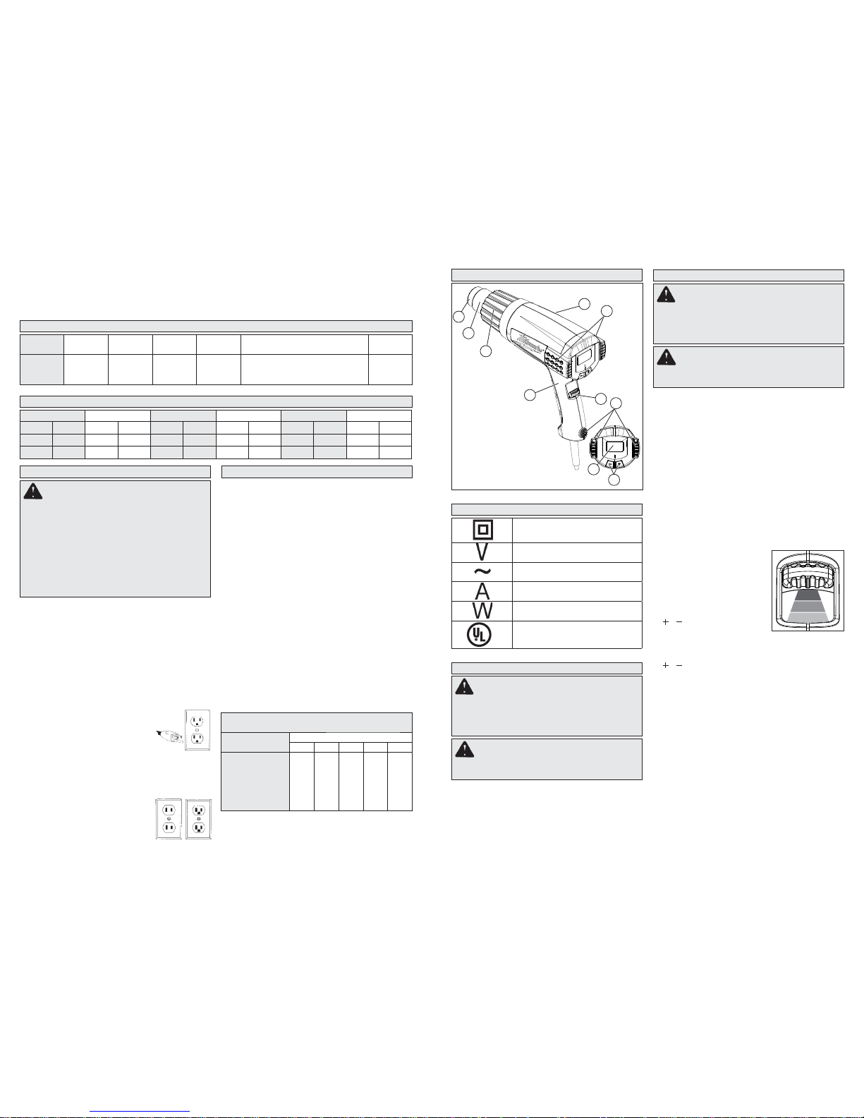
1. Accessory
attachment area
2. Nozzle
3. Front cover
4. Nameplate (on back)
5. Intake vents
6. Handle
7. ON/OFF/Airfl ow switch
8. Support stand bumpers
9. LCD
10. Temperature controls
Grounded Tools: Tools with Three Prong Plugs
T ools marked “Grounding Required” have a three wire
cord and three prong grounding plug. The plug must be
connected to a properly grounded outlet (See Figure
A). If the tool should electrically malfunction or break
down, grounding provides a low resistance path to
carry electricity away from the user, reducing the risk
of electric shock.
The grounding prong in the plug is connected through
the green wire inside the cord to the grounding system
in the tool. The green wire in the cord must be the only
wire connected to the tool's grounding system and
must never be attached to an electrically “live” terminal.
Your tool must be plugged into an appropriate
outlet, properly installed and grounded in accordance with all codes and ordinances.
The plug and outlet should look like
those in Figure A.
Double Insulated Tools: T ools with T wo Prong Plugs
Tools marked “Double Insulated” do not require
grounding. They have a special double insulation
system which satisfi es OSHA requirements and com-
plies with the applicable standards of
Underwriters Laboratories, Inc., the
Canadian Standard Association and
the National Electrical Code. Double
Insulated tools may be used in either of the 120 volt outlets shown in
Figures B and C.
Grounded tools require a three wire extension cord.
Double insulated tools can use either a two or three wire
extension cord. As the distance from the supply outlet
increases, you must use a heavier gauge extension
cord. Using extension cords with inadequately sized
wire causes a serious drop in voltage, resulting in loss
of power and possible tool damage. Refer to the table
shown to determine the required minimum wire size.
The smaller the gauge number of the wire, the greater
the capacity of the cord. For example, a 14 gauge cord
can carry a higher current than a 16 gauge cord. When
using more than one extension cord to make up the total
length, be sure each cord contains at least the minimum
wire size required. If you are using one extension cord for
more than one tool, add the nameplate amperes and use
the sum to determine the required minimum wire size.
Guidelines for Using Extension Cords
•
If you are using an extension cord outdoors, be sure
it is marked with the suffi x “W-A” (“W” in Canada) to
indicate that it is acceptable for outdoor use.
• Be sure your extension cord is properly wired and in
good electrical condition. Always replace a damaged
extension cord or have it repaired by a qualifi ed person
before using it.
• Protect your extension cords from sharp objects,
excessive heat and damp or wet areas.
each work session, place paint scrapings in a double
plastic bag, close it with tape or twist ties and dispose.
• Remove protective clothing and work shoes
in the work area to avoid transferring dust to
Fig. B
Fig. C
GROUNDING
SPECIFICATIONS
* Cubic feet per minute
Cat. No. Volts AC
Max.
Amps
Max.
Watts
Switch
Setting Temperature
Airfl ow
CFM*
8988-20 120 12.5 1500 I
II
III
120°F (49°C)
120°F - 1150°F (49°C - 621°C)
120°F - 1150°F (49°C - 621°C)
3.6
10.6
17.6
READ AND SAVE ALL
INSTRUCTIONS FOR FUTURE USE.
* Based on limiting the line voltage drop to fi ve volts
at 150% of the rated amperes.
EXTENSION CORDS
FUNCTIONAL DESCRIPTION
SYMBOLOGY
Double Insulated
Volts
Alternating Current
Amps
Watts
C
US
Underwriters Laboratories, Inc.
United States and Canada
other parts of the building. Wash work clothes
separately. Wipe shoes off with a wet rag that is then
washed with the work clothes. Wash hair and body
thoroughly with soap and water.
SAVE THESE INSTRUCTIONS
ASSEMBLY
Installing/Removing Nozzles
1. To install, slide the nozzle onto the heat gun
nose.
2. Adjust heat, airfl ow, distance and length of ap-
plication as necessary.
3. To remove, allow tool to cool to room temperature, then pull nozzle away from tool.
OPERATION
Selecting Temperature
The proper amount of heat for each application
depends on the temperature selected, distance
between the nozzle and workpiece, and the length
of time heat is applied. Experiment with scrap materials and start with the lowest temperature. Be
cautious when working until the proper combination
of heat, distance and time of application has been
obtained. Use a back and forth motion when applying heat unless concentrated heat is desirable.
When done, allow the nozzle to cool by placing the
tool upright on a fl at surface using the support stand
areas. Place the cord so the heat gun won’t tip.
The electronic temperature control system
regulates the temperature within the tool's heating element. Unlike non-electronic heat guns,
MILWAUKEE's electronic heat gun will maintain
the temperature.
1. For Low Airfl ow/Low Tem-
perature, push the switch to
the (I) position.
2.For Medium Airflow/Vari-
able Temperature, push
the switch to the (II) position. Use the temperature
/ buttons to increase or
decrease the temperature
(100°F - 1100°F) by 10°F increments.
3. For High Airfl ow/Variable Temperature, push the
switch to the (III) position. Use the temperature
/ buttons to increase or decrease the tem-
perature (100°F - 1100°F) by 10°F increments.
When the tool is switched OFF, the last selected
temperature is retained.
Hands-Free Use
The heat guns can be positioned upright on a stable
surface, leaving both hands free for the application.
Always place the tool upright on a fl at surface using
the support stand areas. Place the cord so the heat
gun won’t tip. The rear vent openings are designed
to allow air fl ow even when the tool is resting on
the end cap. Do not cover the vents with foreign
materials such as clothing or rags.
Types of Nozzles
• Hook Nozzle - Surrounding heat for thin pipe weld-
ing, soft soldering copper pipes, tube shaping and
shrinking of shrink tubes.
• Air Reduction Nozzle - Intensifi ed, spot directed
heat for corners, plexiglas bending and soldering.
WARNING Improperly connecting the
grounding wire can result in the risk of electric
shock. Check with a qualifi ed electrician if you
are in doubt as to whether the outlet is properly
grounded. Do not modify the plug provided with
the tool. Never remove the grounding prong
from the plug. Do not use the tool if the cord or
plug is damaged. If damaged, have it repaired
by a MILWAUKEE service facility before use.
If the plug will not fi t the outlet, have a proper
outlet installed by a qualifi ed electrician.
WARNING To reduce the risk of injury,
do not remove or attach accessory tips until
tool has cooled to room temperature.
WARNING To reduce the risk of injury,
always unplug tool before attaching or removing accessories or making adjustments. Use
only specifi cally recommended accessories.
Others may be hazardous.
WARNING To reduce the risk of injury,
wear safety goggles or glasses with side
shields.
WARNING To reduce the risk of injury,
always unplug tool before attaching or removing accessories or making adjustments. Use
only specifi cally recommended accessories.
Others may be hazardous.
Fig. A
8
2
1
3
6
7
5
4
10
9
Recommended Minimum Wire Gauge
For Extension Cords*
Nameplate Amps
Extension Cord Length
25' 50' 75' 100' 150'
0 - 2.0
2.1 - 3.4
3.5 - 5.0
5.1 - 7.0
7.1 - 12.0
12.1 - 16.0
16.1 - 20.0
18
18
18
18
16
14
12
18
18
18
16
14
12
10
18
18
16
14
12
10
--
18
16
14
12
10
--
--
16
14
12
12
--
--
--
I
II
III
TEMPERATURE CONVERSIONS
°C = °F °C = °F °C = °F °C = °F °C = °F °C = °F
38 100 149 300 260 500 371 700 482 900 593 1100
93 200 200 392 300 572 400 752 500 932 600 1112
100 212 204 400 316 600 427 800 538 1000 649 1200
Page 16
APPLICATIONS
MAINTENANCE
Maintaining Tools
Keep your tool in good repair by adopting a regular
maintenance program. Before use, examine the
general condition of your tool. Inspect guards,
switches, tool cord set and extension cord for
damage. Check for loose screws, misalignment,
binding of moving parts, improper mounting, broken parts and any other condition that may affect
its safe operation. If abnormal noise or vibration
occurs, turn the tool off immediately and have the
problem corrected before further use. Do not use a
damaged tool. T ag damaged tools “DO NOT USE”
until repaired (see “Repairs”).
Cleaning
Clean dust and debris from vents. Keep the tool
handles clean, dry and free of oil or grease. Use
only mild soap and a damp cloth to clean your tool
since certain cleaning agents and solvents are
harmful to plastics and other insulated parts. Some
of these include: gasoline, turpentine, lacquer thinner, paint thinner, chlorinated cleaning solvents,
ammonia and household detergents containing
ammonia. Never use fl ammable or combustible
solvents around tools.
Repairs
If your tool is damaged, return the entire tool to the
nearest service center.
ACCESSORIES
• Defl ector Nozzle - Defl ected heat protects glass
window panes when removing paint and putty.
• Air Spreader Nozzle - Directs heat over large
areas for drying, removing paint, fl oor coverings,
and vinyl tops.
Removing Paint
Read safety instructions for removing paint before
proceeding with paint removal.
1. Begin work with low temperature setting.
2. Place nozzle approximately 1" away from work
surface.
3. Pass nozzle back and forth over a small area of
workpiece.
4. Gradually increase heat until paint starts to
blister, then remove heat.
5. Remove paint using a sharp-edged putty knife.
Creating Bends
Both variable temperature and dual temperature
heat guns are ideal for creating bends in plexiglas
that is used for guards and fi xtures.
1. To form a bend, use either a low or high tempera-
ture setting. When using a low temperature, hold
the heat gun close to the workpiece and pass the
nozzle back and forth slowly. When using a high
temperature, hold the heat gun further away
from the workpiece and pass the nozzle back
and forth rapidly.
2. Pass the nozzle over entire length of the surface
to be bent. Applying heat to only part of the
surface will make bending uneven.
Soldering
1. Attach the air reduction or hook nozzle to the
heat gun.
2. De-burr the pipe and joint using sandpaper or
steel wool.
3. T o solder with either lead or non-lead solder, coat
the tip on both the copper pipe and the joint with
fl ux. Then slip the joint over the pipe.
4. Slip the accessory nozzle around the joint. With
the heat gun at a high temperature setting, apply
heat to the joint.
5. When the fl ux bubbles, add solder and position
heat gun so excess solder does not drip into the
heat gun.
Heat Shrinking
1. Attach the air reduction or hook nozzle to the
heat gun.
2. To heat shrink tubing, use a low temperature
setting. Apply heat to the workpiece using a side
to side motion until tubing has shrunk. Remove
heat immediately.
WARNING To reduce the risk of injury,
electric shock and damage to the tool, never
immerse your tool in liquid or allow a liquid
to fl ow inside the tool.
WARNING To reduce the risk of
injury, always unplug your tool before
performing any maintenance. Never disassemble the tool or try to do any rewiring
on the tool’s electrical system. Contact a
MILWAUKEE service facility for ALL repairs.
WARNING To reduce the risk of heat
damage and personal injury, shield combustible materials and areas adjacent to
workpiece. Protect yourself from hot paint
scrapings and dust.
WARNING To reduce the risk of injury,
always unplug the tool before attaching or
removing accessories. Use only specifi cally
recommended accessories. Others may be
hazardous.
Rely only on high-grade power tools on our virtual shelves.
 Loading...