

Milwaukee 6755-1, 6757-1, 6758-1 Operating Instructions Manual
Removing and Replacing the Quik-Lok® Cord
For instant field replacement, Catalog No. 6755-1 features the
exclusive MILWAUKEE Quik-Lok® Cord.
1. To remove the Quik-Lok® Cord, turn the cord nut 1/4 turn
to the left and pull it out.
2. To replace the Quik-Lok® Cord, align the connector keyways and push the connector in as far as it will go. Turn the
cord nut 1/4 turn to the right to lock.
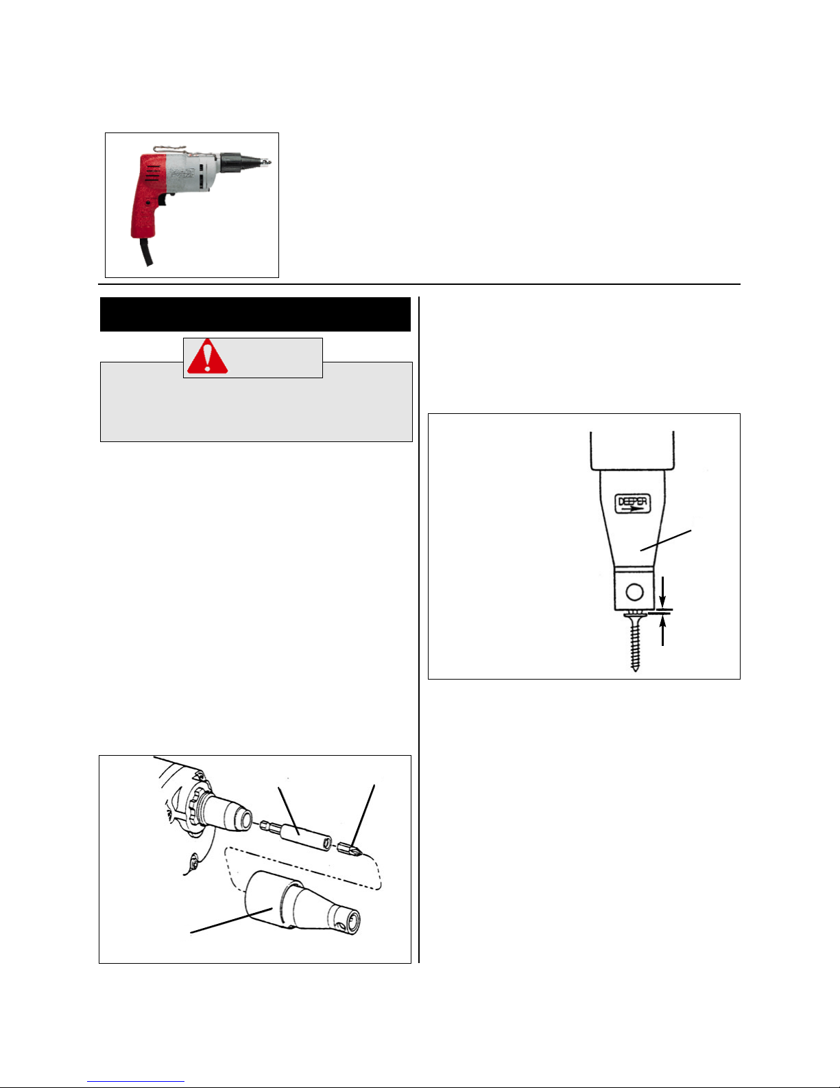
Inserting Bits (Fig 1.)
1. To insert Bit Holders and Bits, unplug tool. Remove Locator
Assembly by pulling it away from the tool.
2. Push Insert Bit into Bit Holder until it snaps into place. Then
push Bit Holder into nose of the tool until it snaps into place.
3. Push Locator Assembly until it snaps into place.
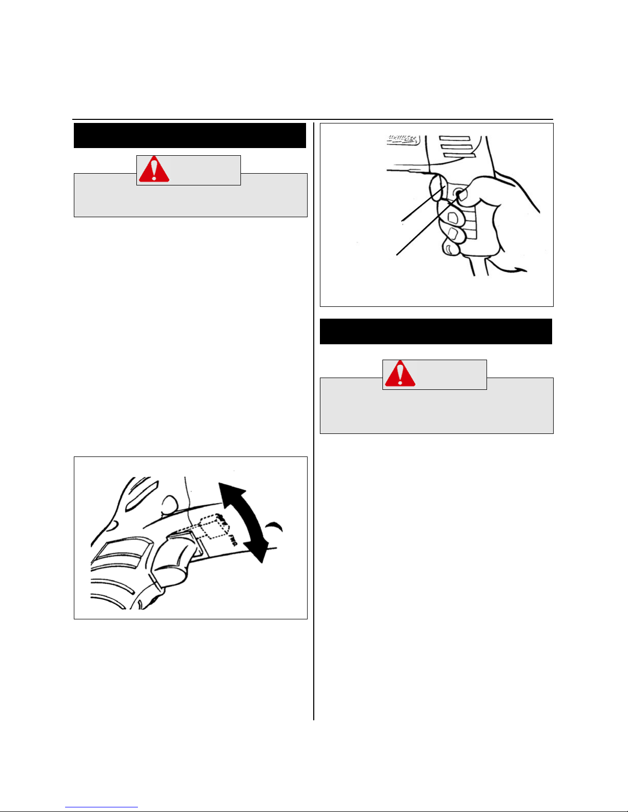
Adjusting Locator Assembly (Fig 2.)
The Locator Assembly controls the driving depth of your tool.
Your MILWAUKEE Drywall Driver features a pop-off Locator
Assembly with a one-handed depth adjustment. Depth adjustments can be made easily and quickly by using one hand to
turn the Locator. Detents inside the Sleeve “lock” the depth
you have selected with the Locator.
Start with about 1/16” clearance between the head of the screw
and Nose with the clutch disengaged as shown. The detents on
the inside of the Sleeve represent different depths. Every two
clicks of the Locator equal 1/64”. Continue adjusting the
Locator until you reach the depth needed for your job.
1. To adjust depth setting, simply rotate the Locator in the
direction labeled. “DEEPER “increases driving depth.
2. Turning Locator in the opposite direction decreases driving depth. The detents will “lock” the Locator in place, ensuring an accurate depth setting.
The pop-off Locator Assembly allows you to remove the
assembly by simply pulling it away from the tool.
Reattachment does not alter your depth setting.
Milwaukee Tool
Heavy-Duty Drywall Screw Driver
Model Numbers: 6755-1, 6757-1, 6758-1
Operating Instructions
Page 1
RenTrain INC
RenTrain INC
To reduce the risk of injury, always unplug tool
before attaching or removing accessories. Use
only specifically recommended accessories.
Others may be hazardous.
WARNING!
ASSEMBLY
Fig. 1
1.
3.
1. Bit Holder
2. Insert Bit
3. Locater assembly
2.
Fig. 2
1.
1. Locater
1/16”
Starting, Stopping and Controlling Speed
Your Drywall Driver may be used at any speed from 0-4000
RPM.
1. To start tool, pull Trigger.
2. To vary the driving speed, simply increase or decrease
pressure on Trigger. The further the Trigger is pulled, the
greater the speed.
3. To stop the tool, release Trigger.
Using Forward/Reverse Switch (Fig 3.)
1. For forward (clockwise) rotation, push the forward/reverse
switch to FWD as shown.
2. For reverse (counterclockwise) rotation, push the
forward/reverse switch to REV as shown. Although an interlock prevents reversing the tool while the motor is running,
allow the motor to come to a full stop before reversing.
Locking Trigger Switch (Fig. 4.)
The Lock Button, located next to the Trigger Switch, holds
Trigger in the ON position for continuous full speed use.
1. To lock Trigger Switch, push Lock Button in while pulling
Trigger. Then release Trigger.
2. To unlock Trigger Switch, pull Trigger and release.
Driving Drywall Screws (See Figs. 5 & 6 - next page)
Standard Drywall Screws are generally designed for attaching
drywall to wood studs and 25 through 20-gauge steel studs.
Your 0-4000 RPM ScrewDriver is ideal for driving these types
of drywall screws. The depth setting is very important. Refer
to the guide at the right for the correct depth setting.
1. To insert screws, select the proper Drywall Screw for each
job. Pilot holes are not needed. Place screw onto the insert bit,
then align the screw against the work surface, making sure you
are holding the tool and screw square to the work surface as
shown at right. If you misalign the tool or the screw, the screw
will not drive into the work surface, or it will not drive straight.
2. Pull the Trigger and push tool forward with a “punching”
motion to sink the screw into the drywall. A punching motion
will engage the clutch, cause the screw to start rotating, sink
the screw and disengage the clutch within a fraction of a second. If you do not maintain pressure on the tool after engaging
the clutch, the screw will not properly seat.
The clutch will automatically disengage and the insert bit will
stop rotating once the screw has been driven to the selected
(Continued on next page)
Operating Instructions (continued)
Page 2
RenTrain INC
RenTrain INC
To reduce the risk of injury, always wear
eye protection.
WARNING!
To reduce the risk of electric shock, check
work area for hidden pipes and wires before
driving screws.
WARNING!
Fig. 3
Fig. 4
1.
1.
2.
2.
OPERATION
APPLICATIONS
1. Trigger
2. Lock button
1. Reverse
2. Forward
 Loading...