

MILWAUKEE 6580-20, 6581-20, 6702-20, 6703-20, 6706-20 User guide
...
OPERATOR'S MANUAL
MANUEL de L'UTILISATEUR
MANUAL del OPERADOR
Catalog No.
No de Cat.
Catálogo No.
FPO
HEAVY-DUTY SCREWDRIVER
EXTRA ROBUSTE TOURNEVIS
6580-20
6581-20
6702-20
6703-20
6706-20
6707-20
6708-20
6740-20
6742-20
6743-20
6790-20
6791-20
6792-20
DESTORNILLADORES HEAVY-DUTY
TO REDUCE THE RISK OF INJURY, USER MUST READ AND UNDERSTAND
OPERATOR'S MANUAL.
AFIN DE RÉDUIRE LE RISQUE DE BLESSURES, L'UTILISATEUR DOIT LIRE ET
BIEN COMPRENDRE LE MANUEL DE L'UTILISATEUR.
PARA REDUCIR EL RIESGO DE LESIONES, EL USUARIO DEBE LEER Y
ENTENDER EL MANUAL DEL OPERADOR.
GENERAL SAFETY RULES
READ AND UNDERSTAND ALL INSTRUCTIONS
Failure to follow all instructions listed below, may result in
electric shock, fire and/or serious personal injury.
SAVE THESE INSTRUCTIONS
WORK AREA
1. Keep your work area clean and
well lit. Cluttered benches and dark
areas invite accidents.
2. Do not operate power tools in ex-
plosive atmospheres, such as in
the presence of flammable liquids, gases, or dust. Power tools
create sparks which may ignite the dust
or fumes.
3. Keep bystanders, children, and
visitors away while operating a
power tool. Distractions can cause
you to lose control. Protect others in
the work area from debris such as
chips and sparks. Provide barriers or
shields as needed.
ELECTRICAL SAFETY
4. Grounded tools must be plugged
into an outlet properly installed
and grounded in accordance with
all codes and ordinances. Never
remove the grounding prong or
modify the plug in any way. Do not
use any adaptor plugs. Check with
a qualified electrician if you are in
doubt as to whether the outlet is
properly grounded. If the tools
should electrically malfunction or break
down, grounding provides a low resistance path to carry electricity away
from the user.
5. Double Insulated tools are
equipped with a polarized plug
(one blade is wider than the other).
This plug will fit in a polarized outlet only one way. If the plug does
not fit fully in the outlet, reverse
the plug. If it still does not fit, contact a qualified electrician to install
a polarized outlet. Do not change
the plug in any way. Double insula-
tion eliminates the need for the
13. Remove adjusting keys or
wrenches before turning the tool
on. A wrench or a key that is left at-
WARNING!
three wire grounded power cord and
grounded power supply system.
6. Avoid body contact with grounded
surfaces such as pipes, radiators,
ranges and refrigerators. There is
an increased risk of electric shock if
your body is grounded.
7. Do not expose power tools to rain
or wet conditions. Water entering a
power tool will increase the risk of electric shock.
8. Do not abuse the cord. Never use
the cord to carry the tools or pull
the plug from an outlet. Keep cord
away from heat, oil, sharp edges
or moving parts. Replace damaged
cords immediately. Damaged cords
increase the risk of electric shock.
9. When operating a power tool out-
side, use an outdoor extension
cord marked “W-A” or “W”. These
cords are rated for outdoor use and
reduce the risk of electric shock.
PERSONAL SAFETY
10. Stay alert, watch what you are doing, and use common sense when
operating a power tool. Do not use
tool while tired or under the influence of drugs, alcohol, or medication. A moment of inattention while op-
erating power tools may result in serious personal injury.
11. Dress properly. Do not wear loose
clothing or jewelry. Contain long
hair. Keep your hair, clothing, and
gloves away from moving parts.
Loose clothes, jewelry, or long hair can
be caught in moving parts.
12. Avoid accidental starting. Be sure
switch is off before plugging in.
Carrying tools with your finger on the
switch or plugging in tools with the
switch on invites accidents.
tached to a rotating part of the tool may
result in personal injury.
14. Do not overreach. Keep proper
footing and balance at all times.
Proper footing and balance enables
better control of the tool in unexpected
situations.
15. Use safety equipment. Always
wear eye protection. Dust mask,
non-skid safety shoes, hard hat, or
hearing protection must be used for appropriate conditions.
TOOL USE AND CARE
16. Use clamps or other practical way
to secure and support the workpiece to a stable platform. Holding
the work by hand or against your body
is unstable and may lead to loss of control.
17. Do not force tool. Use the correct
tool for your application. The correct tool will do the job better and safer
at the rate for which it is designed.
18. Do not use tool if switch does not
turn it on or off. Any tool that cannot
be controlled with the switch is dangerous and must be repaired.
19. Disconnect the plug from the
power source before making any
adjustments, changing accessories, or storing the tool. Such pre-
ventive safety measures reduce the
risk of starting the tool accidentally.
20. Store idle tools out of reach of chil-
dren and other untrained persons.
Tools are dangerous in the hands of
untrained users.
21. Maintain tools with care. Keep cut-
ting tools sharp and clean. Properly
maintained tools with sharp cutting edge
are less likely to bind and are easier to
control. Do not use a damaged tool.
Tag damaged tools “Do not use” until
repaired.
22. Check for misalignment or bind-
ing of moving parts, breakage of
parts, and any other condition that
may affect the tool’s operation. If
damaged, have the tool serviced
before using. Many accidents are
caused by poorly maintained tools.
2 3
23. Use only accessories that are rec-
ommended by the manufacturer
for your model. Accessories that may
be suitable for one tool, may become
hazardous when used on another tool.
SERVICE
24. Tool service must be performed
only by qualified repair personnel.
Service or maintenance performed by
unqualified personnel could result in a
risk of injury.
25. When servicing a tool, use only
identical replacement parts.
Follow instructions in the Maintenance section of this manual. Use
of unauthorized parts or failure to follow Maintenance Instructions may create a risk of electric shock or injury.
SPECIFIC SAFETY RULES
1. Hold tool by insulated gripping sur-
faces when performing an operation where the cutting tool may
contact hidden wiring or its own
cord. Contact with a “live” wire will
make exposed metal parts of tool “live”
and shock the operator.
2. Maintain labels and nameplates.
These carry important information. If
unreadable or missing, contact a
WAUKEE
placement.
3. WARNING! Some dust created by
power sanding, sawing, grinding, drilling, and other construction activities
contains chemicals known to cause
cancer, birth defects or other reproductive harm. Some examples of these
chemicals are:
• lead from lead-based paint
• crystalline silica from bricks and
• arsenic and chromium from chemi-
Your risk from these exposures varies, depending on how often you do
this type of work. To reduce your exposure to these chemicals: work in a
well ventilated area, and work with
approved safety equipment, such as
those dust masks that are specifically
designed to filter out microscopic particles.
service facility for a free re-
cement and other masonry products,
and
cally-treated lumber.
MIL-
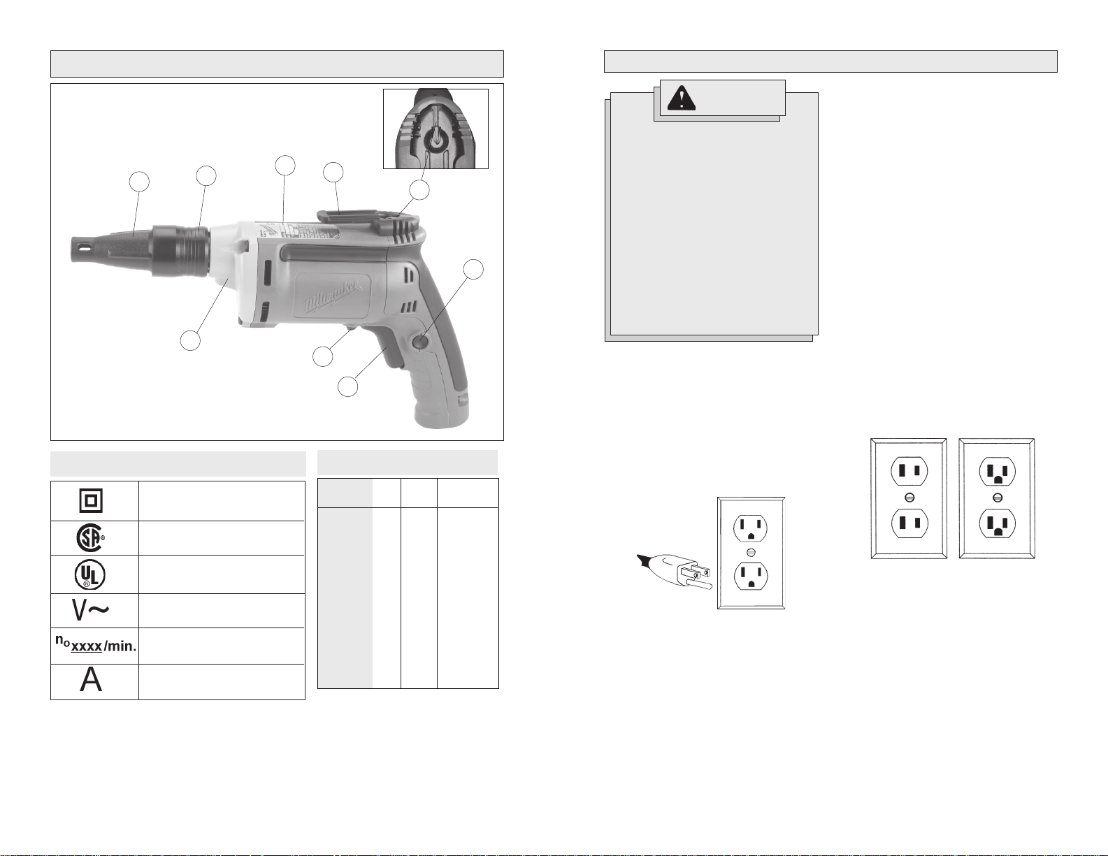
FUNCTIONAL DESCRIPTION
GROUNDING
1
1. Locator
2. Ramp-off sleeve
3. Nameplate
4. Belt clip
5. Bit clip
6. Lock button
7. Trigger
8. Forward/Reverse switch
9. Gear case
9
Symbology
Double Insulated
Canadian Standards
Association
Underwriters
Laboratories, Inc.
Volts Alternating Current
No Load Revolutions
per Minute (RPM)
Amperes
WARNING!
Improperly connecting the
grounding wire can result in the
2
3
4
FPO
8
7
5
6
Specifications
Catalog
Number
6580-20
6581-20
6702-20
6703-20
6706-20
6707-20
6708-20
6740-20
6742-20
6743-20
6790-20
6791-20
6792-20
Volts
AC
120
120
120
120
120
120
120
120
120
120
120
120
120
120
Amps
6.5
6.5
6.5
6.5
6.5
6.5
6.5
6.5
6.5
6.5
6.5
6.5
6.5
6.5
RPM
0 - 1200
0 - 2500
0 - 2500
0 - 4000
0 - 2500
0 - 4000
0 - 2500
0 - 2500
0 - 4000
0 - 4000
0 - 2500
0 - 2500
0 - 2500
0 - 2500
risk of electric shock. Check
with a qualified electrician if you
are in doubt as to whether the
outlet is properly grounded. Do
not modify the plug provided
with the tool. Never remove the
grounding prong from the plug.
Do not use the tool if the cord or
plug is damaged. If damaged,
have it repaired by a
service facility before use. If the
plug will not fit the outlet, have a
proper outlet installed by a qualified electrician.
Grounded Tools:
Tools with Three Prong Plugs
Tools marked “Grounding Required” have
a three wire cord and three prong grounding plug. The plug must be connected to a
properly grounded outlet (See Figure A). If
the tool should electrically malfunction or
break down, grounding provides a low resistance path to carry electricity away from
the user, reducing the risk of electric shock.
MILWAUKEE
Fig. A
The grounding prong in the plug is connected through the green wire inside the
cord to the grounding system in the tool.
The green wire in the cord must be the
only wire connected to the tool's grounding system and must never be attached to
an electrically “live” terminal.
Your tool must be plugged into an appropriate outlet, properly installed and
grounded in accordance with all codes and
ordinances. The plug and outlet should look
like those in Figure A.
Double Insulated Tools:
Tools with Two Prong Plugs
T ools marked “Double Insulated” do not require grounding. They have a special
double insulation system which satisfies
OSHA requirements and complies with the
applicable standards of Underwriters Laboratories, Inc., the Canadian Standard Association and the National Electrical Code.
Double Insulated tools may be used in either of the 120 volt outlets shown in
Figures B and C.
Fig. B
Fig. C
4 5
EXTENSION CORDS
TOOL ASSEMBLY
Grounded tools require a three wire extension cord. Double insulated tools can
use either a two or three wire extension
cord. As the distance from the supply outlet increases, you must use a heavier
gauge extension cord. Using extension
cords with inadequately sized wire causes
a serious drop in voltage, resulting in loss
of power and possible tool damage. Refer
to the table shown to determine the required minimum wire size.
The smaller the gauge number of the wire,
the greater the capacity of the cord. For
example, a 14 gauge cord can carry a
higher current than a 16 gauge cord. When
using more than one extension cord to make
up the total length, be sure each cord contains at least the minimum wire size required. If you are using one extension cord
for more than one tool, add the nameplate
amperes and use the sum to determine the
required minimum wire size.
Guidelines for Using Extension Cords
• If you are using an extension cord outdoors, be sure it is marked with the
suffix “W-A” (“W” in Canada) to indicate that it is acceptable for outdoor
use.
• Be sure your extension cord is properly wired and in good electrical
condition. Always replace a damaged
extension cord or have it repaired by a
qualified person before using it.
• Protect your extension cords from
sharp objects, excessive heat and
damp or wet areas.
Recommended Minimum Wire
Gauge for Extension Cords*
Nameplate
Amperes
0 - 2.0
2.1 - 3.4
3.5 - 5.0
5.1 - 7.0
7.1 - 12.0
12.1 - 16.0
16.1 - 20.0
* Based on limiting the line voltage drop to
five volts at 150% of the rated amperes.
Extension Cord Length
75'
100'
18
16
14
12
10
150'
16
14
12
12
25'
18
18
18
18
16
14
12
50'
18
18
18
16
14
12
10
18
18
16
14
12
10
WARNING!
To reduce the risk of injury,
always unplug tool before attaching or removing accessories
or making adjustments. Use only
specifically recommended accessories. Others may be hazardous.
Removing and Replacing Quik-Lok
Cords (Fig. 1) Cat. No. 6580-20, 6581-20,
6702-20, 6703-20, 6706-20, 6707-20,
6708-20, 6791-20
MILWAUKEE
provide instant field replacement or
substitution.
Fig. 1
1. T o remove the Quik-Lok® Cord, turn the
cord nut 1/4 turn to the left and pull it
out.
2. To replace the Quik-Lok
connector keyways and push the connector in as far as it will go. Turn the
cord nut 1/4 turn to the right to lock.
's exclusive Quik-Lok® Cords
®
Cord, align the
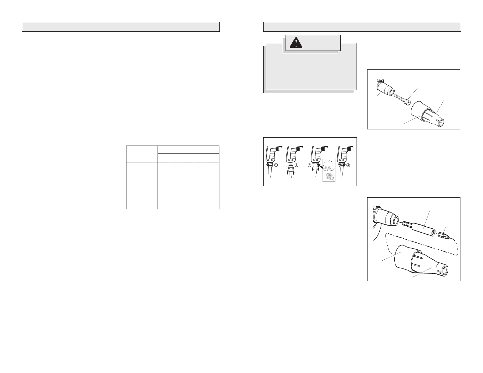
Installing and Removing Bits (Fig. 2)
TEKS Ramp-Off Locator Assembly
The locator assembly must be removed
when changing bit sizes.
Fig. 2
Magnetic socket
®
Ramp-off
sleeve
1. Unplug tool. To remove the locator assembly, turn the ramp-off sleeve while
pulling it away from the tool.
2. Pull out the magnetic socket and replace it with a new socket.
3. Push the locator assembly onto the nose
of the tool until it snaps into place.
Installing and Removing Bits (Fig. 3)
Drywall Ramp-Off Locator Assembly
Fig. 3
Bit holder
Locator
Insert bit
READ AND SA VE ALL INSTRUCTIONS FOR FUTURE USE.
6 7
Installing Driving Mechanism
Cat. No. 6706-20, 6707-20, 6708-20
Install the final driving mechanism according to the instructions included with the
tool's attachment.
Ramp-off
sleeve
Locator
1. Unplug tool. To remove the locator assembly, turn the ramp-off sleeve while
pulling it away from the tool.
2. Push insert bit into bit holder until it snaps
into place. Push the bit holder into the
nose of the tool until it snaps into place.
3. Push the locator assembly onto the nose
of the tool until it snaps into place.
OPERATION
WARNING!
To reduce the risk of injury, wear
safety goggles or glasses with
side shields. Unplug the tool before changing accessories or
making adjustments.
Using Forward/Reverse Switch (Fig. 4)
Fig. 4
Switch
1. For forward (clockwise) rotation, push
the forward/reverse switch to the left
position as shown.
2. For reverse (counterclockwise) rotation, push the forward/reverse switch
to the right position as shown.
Although an interlock prevents reversing the tool while the motor is running,
allow it to come to a full stop before
reversing.
Forward
Reverse
Trigger
WARNING!
To reduce the risk of injury, keep
hands and cord away from the bit
and all moving parts.
2. To unlock the trigger, pull the trigger
and release. The lock button will pop
out.
Fig. 5
Lock
button
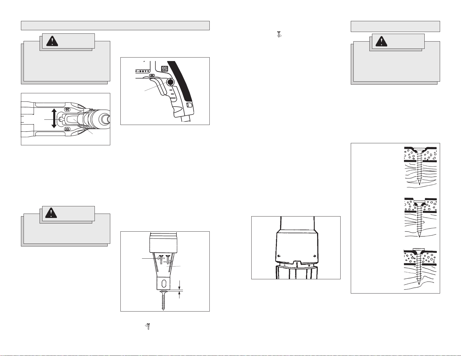
Adjusting Locator Assembly (Fig. 6)
The locator assembly controls the tool's
driving depth. These screwdrivers feature
a locator assembly with one-handed depth
adjustment. Depth adjustments can be
made easily and quickly by turning the locator with one hand. Detents inside the
sleeve “lock” the selected depth.
For the drywall ramp-off locator assembly, start with about 1/16" clearance between the head of the screw and nose
with the snap-action clutch disengaged as
shown.
For both locator assemblies, the detents
on the inside of the sleeve represent different depths. Every two clicks of the locator equal 1/64". Continue adjusting the
locator to the desired depth.
Fig. 6
2. To decrease the driving depth, simply
rotate the locator in the direction
labeled .
The detents “lock” the locator in place,
ensuring an accurate depth setting.
3. To remove the locator assembly, turn
the ramp-off sleeve while pulling it
away from the tool. Reattaching the locator assembly will not change the
depth setting.
Adjusting Torque Setting (Fig. 7)
Cat. No. 6580-20, 6581-20
These screwdrivers have a torque setting
adjustment collar for driving different types
of screws into different materials. When
properly adjusted, the clutch will slip at a
preset torque to prevent driving the screw
too deep and to prevent damage to the
screw or tool.
The 6580-20 Screwdriver has a torque
setting adjustment collar that may be adjusted to one of forty-four settings. The
torque is adjustable from 10 to 140 inchpounds.
The 6581-20 Screwdriver has a torque
setting adjustment collar that may be adjusted to one of thirty-three settings. Beyond setting thirty-three, the tool will stall
before slipping the clutch. The torque is
adjustable from 10 to 110 inch-pounds.
To select a setting, turn the adjustment
collar in the direction indicated on the tool.
The selected setting will appear in the window as shown (Fig. 7).
Fig. 7
APPLICATIONS
WARNING!
To reduce the risk of explosion,
electric shock and property
dammage. always check the
work area for hidden pipes and
wires before drilling.
Driving Drywall Screws (Fig. 8)
For Screwdrivers Rated 0-4000 RPM
Standard drywall screws are generally designed for attaching drywall to wood studs
and 26 through 20-gauge steel studs.
MILWAUKEE
driving these types of drywall screws. The
depth setting is very important. Refer to
the guide below for the correct depth setting (Fig. 8).
Fig. 8
Correct. Head of
screw is below surface, but does not
puncture facing.
Too deep. Head of
screw punches hole in
drywall surface, making finishing difficult
and allowing moisture
beneath facing. Decrease depth.
Screwdrivers are ideal for
Starting, Stopping and Controlling
Speed
1. To start the tool, pull the trigger.
2. To stop the tool, release the trigger.
3. To vary the drilling speed, simply increase or decrease pressure on the
trigger. The further the trigger is pulled,
the greater the speed.
Locking Trigger (Fig. 5)
The lock button holds the trigger in the ON
position for continuous full speed use.
1. To lock the trigger, hold the lock button
in while pulling the trigger. Release the
trigger.
HIGHER -TORQUE - LOWER
Deeper
Locator
1/16"
1. To increase the driving depth, simply
rotate the locator in the direction
labeled .
NOTE: Use a piece of scrap material to
test the different settings before driving
screws into workpiece. T o determine a specific setting for your application, use a
torque wrench to check the correct torque
at any particular setting.
SETTING
8 9
Too shallow. Head of
screw extends above
drywall face and can
not be finished off.
Incease depth.
1. Select the proper drywall screw for
each job. Pilot holes are not needed. T o
insert screws, place the screw onto
the insert bit, then align the screw
against the work surface, making sure
to hold the tool and screw square to
the work surface.
If the tool or screw are misaligned, the
screw will not drive into the work surface or it will not drive straight.
2. Pull the trigger and push the tool forward with a “punching” motion to sink
the screw into the drywall. A punching
motion will engage the snap-action
clutch, cause the screw to start rotating, sink the screw and disengage the
snap-action clutch within a fraction of
a second. If pressure is not maintained
on the tool after engaging the snapaction clutch, the screw will not properly seat.
The snap-action clutch will automatically disengage and the insert bit will
stop rotating once the screw has been
driven to the selected depth.
These screwdrivers feature a snapaction clutch, which may ratchet slightly
when the screw is sunk to the selected
depth.
NOTE: Practice driving screws into
pieces of scrap material to become
familiar with the tool and the snapaction clutch action before attempting
to drive screws into the workpiece.
3. To remove screws, remove the locator
assembly and switch the forward/
reverse switch to the reverse position.
Reattaching the locator assembly will
not change the depth setting.
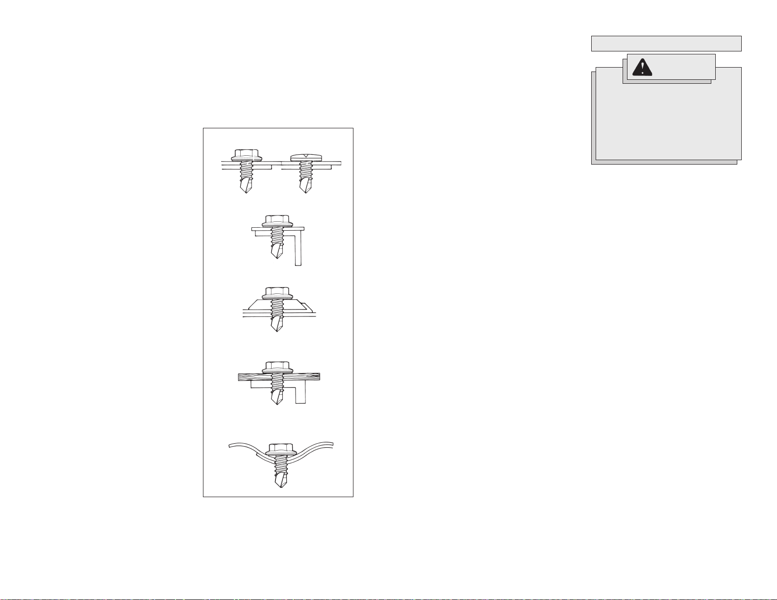
Driving Self-Drilling Screws into
Cold-Formed Steel Framing (Fig. 9)
For Screwdrivers Rated 0-2500 RPM
When working with light gauge sheet metal,
20 gauge and thicker, follow the same procedure as with wood studs. See “Adjusting Locator Assembly” for setting driving
depth.
The screw may hesitate slightly when it
finishes breaking through the drywall and
starts to penetrate the sheet metal. This is
normal. Remember to use a “punching”
motion to drive the screw and keep firm
pressure on the tool until the screw is
seated.
Self-drilling and self-tapping screws drill,
tap and fasten in one quick, easy motion
without a separate drilling operation. Their
unique design works in metal up to 1/2"
thick, giving a strong, reliable hold. The drill
point ensures rapid drilling and consistently
low drilling pressure while the drill flutes
remove drilling chips. The pilot section ensures that drilling is completed before the
first thread engages the material. These
screws can be used in many applications
as shown at the right.
The depth setting is very important. See
“Adjusting Locator Assembly” for setting
driving depth.
Fig. 9
Sheet to sheet
Sheet to structure
Structure to structure
Wood to structure
Corrugated siding
1. Insert screw into the insert bit and align
the bit against the work surface.
2. Pull the trigger while pushing the tool
forward. This motion will engage the
snap-action clutch, causethe screw to
start rotating, sink the screw and disengage the snap-action clutch within a
fraction of a second. If pressure is not
maintained on the tool after engaging
the snap-action clutch, the screw will
not properly seat.
The snap-action clutch will automatically disengage and the insert bit will
stop rotating once the screw has been
driven to the selected depth.
These screwdrivers feature a snapaction clutch, which may ratchet slightly
when the screw is sunk to the selected
depth.
NOTE: Practice driving screws into
pieces of scrap material to become
familiar with the tool and the snapaction clutch action before attempting
to drive screws into the workpiece.
3. To remove screws, remove the locator
assembly and switch the forward/
reverse switch to the reverse position.
Reattaching the locator assembly will
not change the depth setting.
Driving Wood Screws
When driving wood screws, a pilot hole is
recommended to make driving easier and
to prevent splitting the wood. As a general
rule, the pilot hole should have a diameter
of approximately 70% the size of the
screw diameter. Hardwood pilot holes
should have a diameter of approximately
90% the size of the screw diameter. The
depth of the pilot hole should be shorter
than the length of the screw by at least
one screw diameter. This allows the tip of
the screw to bite into the wood for extra
holding power.
Counterbore the top portion of the hole for
a free fit of the shank between the screw
head and the threads. When using flat head
screws, countersink the top of the hole to
allow the screw head to be driven flush
with the work surface. Use soap or wax
for easier screw insertion if necessary.
10 11
MAINTENANCE
WARNING!
To reduce the risk of injury, always unplug your tool before
performing any maintenance.
Never disassemble the tool or try
to do any rewiring on the tool's
electrical system. Contact a
MILWAUKEE
ALL repairs.
Maintaining Tools
Keep your tool in good repair by adopting a
regular maintenance program. Before use,
examine the general condition of your tool.
Inspect guards, switches, tool cord set and
extension cord for damage. Check for
loose screws, misalignment, binding of
moving parts, improper mounting, broken
parts and any other condition that may affect its safe operation. If abnormal noise
or vibration occurs, turn the tool off immediately and have the problem corrected
before further use. Do not use a damaged
tool. T ag damaged tools “DO NOT USE” until
repaired (see “Repairs”).
Under normal conditions, relubrication is
not necessary until the motor brushes
need to be replaced. After six months to
one year, depending on use, return your
tool to the nearest
facility for the following:
• Lubrication
• Brush inspection and replacement
• Mechanical inspection and cleaning
(gears, spindles, bearings, housing,
etc.)
• Electrical inspection (switch, cord,
armature, etc.)
• Testing to assure proper mechanical
and electrical operation
Cleaning
Clean dust and debris from vents. Keep
the tool handles clean, dry and free of oil
or grease. Use only mild soap and a damp
cloth to clean your tool since certain cleaning agents and solvents are harmful to plastics and other insulated parts. Some of
these include: gasoline, turpentine, lacquer
thinner, paint thinner, chlorinated cleaning
solvents, ammonia and household detergents containing ammonia. Never use flammable or combustible solvents around tools.
service facility for
MILWAUKEE
service
 Loading...