

Page 1
OPERATOR'S MANUAL
MANUEL de L'UTILISATEUR
MANUAL del OPERADOR
Catalog No.
No de Cat.
Catálogo No.
6497
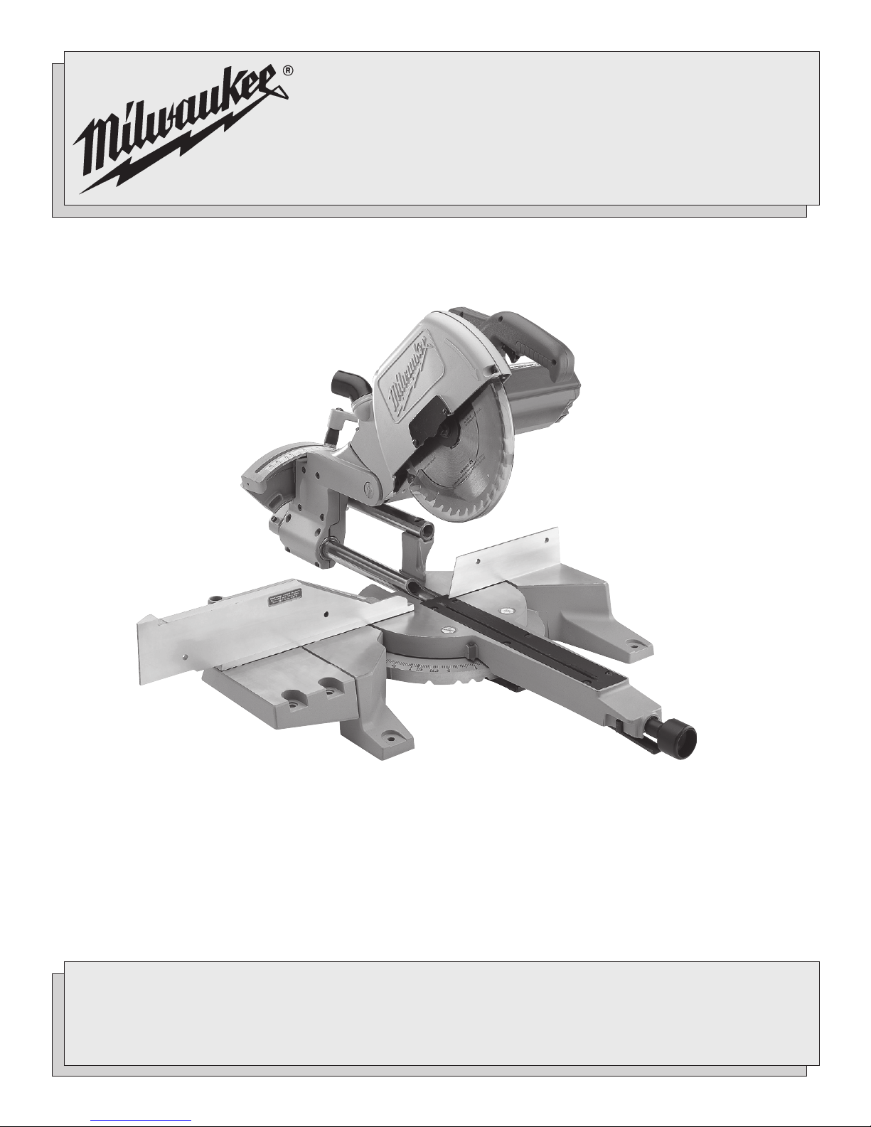
10" MAGNUM® SLIDE COMPOUND MITER SAW
SCIE À ONGLETS COMBINÉE COULISSANTE MAGNUM® 254 mm (10")
SIERRA ANGULAR DE DISCOS DE CORTE COMPUESTO MAGNUM®, DE
254 mm (10") DE DIÁMETRO
TO REDUCE THE RISK OF INJURY, USER MUST READ AND UNDERSTAND OPERATOR'S MANUAL.
AFIN DE RÉDUIRE LE RISQUE DE BLESSURES, L'UTILISATEUR DOIT LIRE ET BIEN COMPRENDRE LE
MANUEL DE L'UTILISATEUR.
PARA REDUCIR EL RIESGO DE LESIONES, EL USUARIO DEBE LEER Y ENTENDER EL MANUAL DEL
OPERADOR.
Page 2

page 2
Page 3
GENERAL SAFETY RULES
WARNING!
READ AND UNDERSTAND ALL INSTRUCTIONS
Failure to follow all instructions listed below, may result in
electric shock, fire and/or serious personal injury.
SAVE THESE INSTRUCTIONS
WORK AREA
1. Keep work area clean and well lit. Cluttered, dark work areas
invite accidents.
2. Avoid dangerous environments. Do not use your power tool in
rain, damp or wet locations or in the presence of explosive atmospheres (gaseous fumes, dust or flammable materials). Remove
materials or debris that may be ignited by sparks.
3. Keep bystanders away. Children and bystanders should be kept
at a safe distance from the work area to avoid distracting the operator and contacting the tool or extension cord.
4. Protect others in the work area from debris such as chips and
sparks. Provide barriers or shields as needed.
5. Make workshop child proof with padlocks, master switches, or
by removing starter keys.
ELECTRICAL SAFETY
6. Grounded tools must be plugged into an outlet properly
installed and grounded in accordance with all codes and
ordinances. Never remove the grounding prong or modify the plug
in any way. Do not use any adaptor plugs. Check with a qualified
electrician if you are in doubt as to whether the outlet is properly
grounded. If the tool should electrically malfunction or break down,
grounding provides a low resistance path to carry electricity away
from the user.
7. Double insulated tools are equipped with a polarized plug
(one blade is wider than the other). This plug will fit in a
polarized outlet only one way. If the plug does not fit fully in
the outlet, reverse the plug. If it still does not fit, contact a
qualified electrician to install a polarized outlet. Do not change
the plug in any way. Double insulation eliminates the need for
the three wire grounded power cord and grounded power supply
system.
8. Guard against electric shock. Prevent body contact with
grounded surfaces such as pipes, radiators, ranges and refrigerators. When making blind or plunge cuts, always check the work area
for hidden wires or pipes. Hold your tool by insulated nonmetal
grasping surfaces. Use a Ground Fault Circuit Interrupter (GFCI) to
reduce shock hazards.
9. Do not expose to rain or use in damp locations.
10. Do not abuse the cord. Never use the cord to carry the tools
or pull the plug from an outlet. Keep cord away form heat,
oil, sharp edges or moving parts. Replace damaged cords
immediately. Damaged cords increase the risk of electric shock.
PERSONAL SAFETY
11. Know your power tool. Read this manual carefully to learn your
power tool’s applications and limitations as well as potential hazards associated with this type of tool.
12. Stay alert, watch what you are doing, and use common sense
when operating a power tool. Do not use tool while tired or
under the influence of drugs, alcohol, or medication. A mo-
ment of inattention while operating power tools may result in serious
personal injury.
13. Dress properly. Do not wear loose clothing or jewelry. Wear a
protective hair covering to contain long hair. These may be caught in
moving parts. When working outdoors, wear rubber gloves and
insulated non-skid footwear. Keep hands and gloves away from
moving parts.
14. Reduce the risk of unintentional starting. Be sure your tool is
turned off before plugging it in. Do not use a tool if the power switch
does not turn the tool on and off. Do not carry a plugged-in tool with
your finger on the switch.
15. Remove all adjusting keys and wrenches. Make a habit of
checking that adjusting keys, wrenches, etc. are removed from the
tool before turning it on.
16. Do not overreach. Maintain control. Keep proper footing and
balance at all times. Maintain a firm grip. Use extra care when using
tool on ladders, roofs, scaffolds, etc.
17. Use safety equipment. Everyone in the work area should wear
safety goggles or glasses with side shields complying with
current safety standards. Everyday eyeglasses only have impact
resistant lenses. They are not safety glasses. Wear hearing protection during extended use and a dust mask for dusty operations. Hard
hats, face shields, safety shoes, etc. should be used when specified or necessary. Keep a fire extinguisher nearby.
18. Keep guards in place and in working order.
19. Never stand on tool. Serious injury could occur if the tool is tipped
or if the cutting tool is unintentionally contacted.
20. Keep hands away from all cutting edges and moving parts.
TOOL USE AND CARE
21. Secure work. Use a clamp, vise or other practical means to hold
your work securely, freeing both hands to control the tool.
22. Do not force tool. Your tool will perform best at the rate for which
it was designed. Excessive force only causes operator fatigue,
increased wear and reduced control.
23. Use the right tool. Do not use a tool or attachment to do a job for
which it is not recommended. For example, do not use a circular
saw to cut tree limbs or logs. Do not alter a tool.
24. Unplug tool when it is not in use, before changing accessories or
performing recommended maintenance.
25. Store idle tools. When not in use, store your tool in a dry, secured
place. Keep out of reach of children.
26. Never leave the tool running unattended. Turn power off. Do
not leave the tool until it comes to a complete stop.
27. Check for damaged parts. Inspect guards and other parts be-
fore use. Check for misalignment, binding of moving parts, improper
mounting, broken parts and any other conditions that may affect
operation. If abnormal noise or vibration occurs, turn the tool off
immediately and have the problem corrected before further use. Do
not use a damaged tool. Tag damaged tools “DO NOT USE” until
repaired. A guard or other damaged part should be properly repaired
or replaced by a MILWAUKEE service facility. For all repairs, insist
on only identical replacement parts.
page 3
Page 4

28. Use proper accessories. Consult this manual for recommended
accessories. Using improper accessories may be hazardous. Be
sure accessories are properly installed and maintained. Do not defeat a guard or other safety device when installing an accessory or
attachment.
29. Maintain tools carefully. Keep handles dry, clean and free from
oil and grease. Keep cutting edges sharp and clean. Follow instructions for lubricating and changing accessories. Periodically inspect
tool cords and extension cords for damage. Have damaged parts
repaired or replaced by a MILWAUKEE service facility.
30. Maintain labels & nameplates. These carry important informa-
tion. If unreadable or missing, contact a MILWAUKEE service facility for a free replacement.
SPECIFIC SAFETY RULES
SERVICE
31. Tool service must be performed only by qualified repair
personnel. Service or maintenance performed by unqualified per-
sonnel may result in a risk of injury.
32. When servicing a tool, use only identical replacement parts.
follow instructions in the maintenance section of this
manual. Use of unauthorized parts or failure to follow maintenance
instructions may create a risk of shock or injury.
1. WARNING! Some dust created by power sanding, sawing, grinding,
drilling, and other construction activities contains chemicals known
to cause cancer, birth defects or other reproductive harm. Some
examples of these chemicals are:
• lead from lead-based paint
• crystalline silica from bricks and cement and other masonry
products, and
• arsenic and chromium from chemically-treated lumber.
Your risk from these exposures varies, depending on how often
you do this type of work. To reduce your exposure to these chemicals: work in a well ventilated area, and work with approved safety
equipment, such as those dust masks that are specifically designed
to filter out microscopic particles.
2. Always keep hands away from the path of the saw blade.
3. Do not defeat the guards of operate the tool without the
guards in place.
4. Always support work properly. Use the fence, support blocks,
auxiliary work support or clamps to keep workpiece secure. Always support the free end of the workpiece and support all small
workpieces. Workpieces that bow and pinch the blade may result in
kick back. Do not perform any operations freehand (unsupported).
5. Never reach around, under or across blade.
6. Check guards for smooth operation before each use.
7. Avoid kick back. Kick back is a violent reaction to a pinched or
binding blade, which throws the saw head upward and towards
the operator. Proper workpiece selection and support, proper blade
selection and maintenance, and even feed rate are essential to
reduce the risk of kick back.
8. Always wait for the blade to stop completely before changing positions, retrieving a cut-off piece, or preparing the next cut.
Unplug the tool before tightening blade screw, servicing, making
adjustments, transporting or moving the saw to another location.
9. Be sure the clamp handle and the bevel adjustment lever
are tightened securely before making cuts.
10. Do not use abrasive wheels with the miter saw.
11. Use the right blade. Use only recommended blade types and
sizes with proper mounting holes, rated at least 5500 RPM. Follow
the rotation arrow on the blade to be sure you install it properly.
Keep saw blades sharp to help prevent cracking and grabbing.
Never use defective or incorrect washers or bolts.
12. Do not lock the trigger in the on position.
13. Wait for the blade to reach full speed before lowering the
saw head to make a cut.
14. Keep the cord away from the cutting area and position it so that
it will not be tripped over or caught on the workpiece while you are
cutting.
15. Do not place hands under the saw motor or in the path of
the blade. Do not retrieve a piece of material that is cut off while the
blade is rotating. Never place hands or fingers behind or in front of
the saw blade.
16. Keep blades clean and sharp. An unsharpened or improperly
sharpened blade produces a narrow kerf and is likely to be pinched
by the workpiece. A dull blade produces excessive friction which
can cause the blade to warp or bind. Be sure the blade screw is
tight to prevent slipping or loosening during operation.
17. Restarting in mid-cut. If you stop the saw in mid-cut, allow the
blade to stop, then raise the saw out of the cut. Then restart the
saw.
18. If the blade stalls, do not turn the switch on and off. A dull
blade or excess pressure may cause stalling. Release the switch
immediately if the blade binds or the saw stalls and remove the saw
from the cut.
19. Avoid cutting nails. Inspect for and remove all nails before cutting.
20. Thin material tends to warp or sag and must be well-supported
over its entire length to avoid pinching the blade.
21. Position fence properly. The flip fence can be adjusted for com-
pound cuts and miter cuts. Always make sure the fence is adjusted
for the intended cut. Never operate the saw without the fence in
place.
22. Lock the saw head down and lock the sliding mechanism
before transporting.
23. Push the saw through the workpiece. Do not pull the saw
through the workpiece. To make a cut, raise saw head and pull it
out OVER the workpiece WITHOUT cutting, start the motor, wait a
few seconds for the blade to reach full speed, press down on saw
head, and push saw head through the cut.
page 4
Page 5
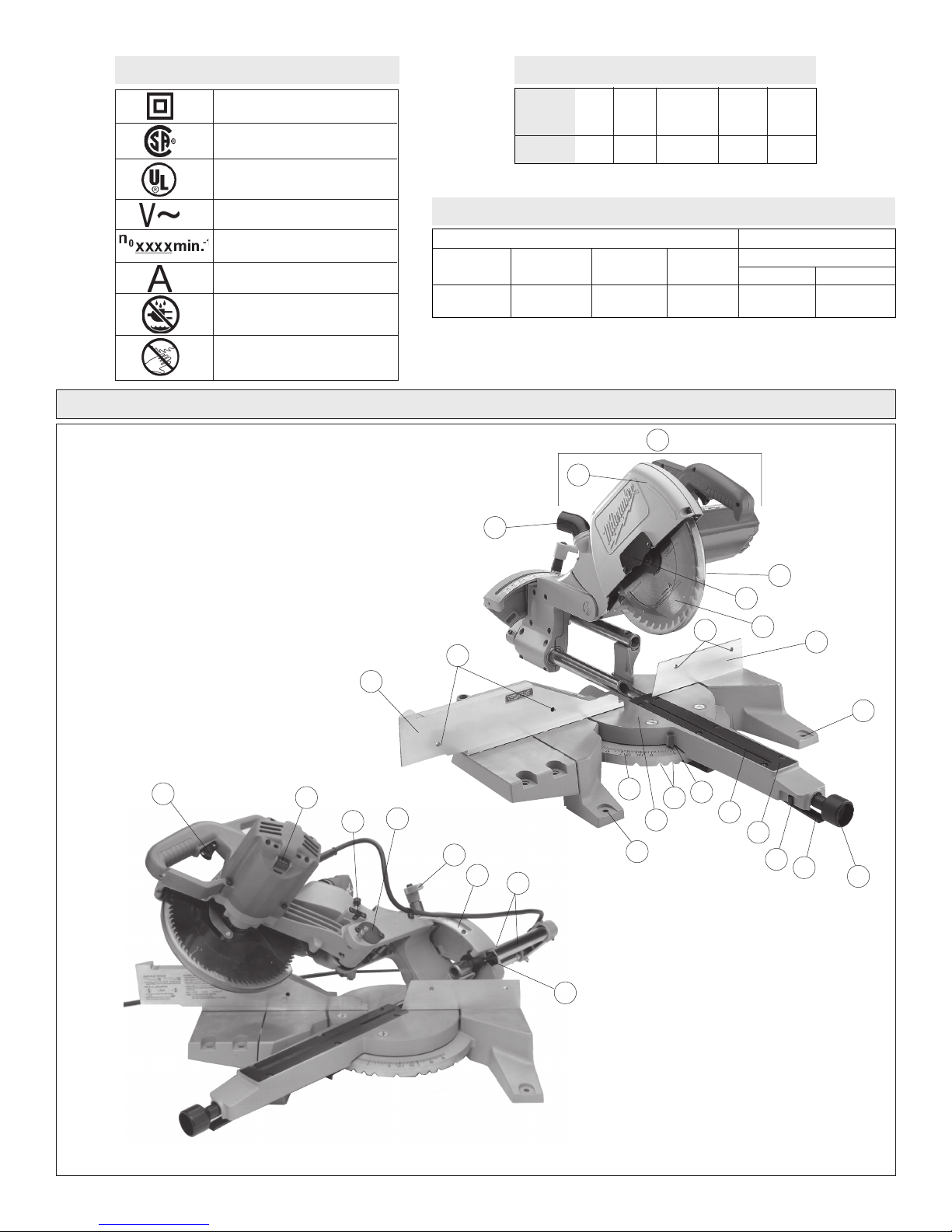
Symbology
Specifications
1. Saw head
2. Upper guard
3. Lower guard
4. Blade screw guard
5. Blade
6. Fence
7. Clamp handle
8. Detent override lever
9. Detent override lock
10. Kerf plate
11. Kerf plate slot
12. Pointer
13. Positive angle stops
14. Turntable
15. Miter angle scale
16. Mounting holes (4)
Double Insulated
Canadian Standards
Association
Underwriters
Laboratories, Inc.
Volts Alternating Current
No Load Revolutions
per Minute (RPM)
Amperes
Do not expose to rain or use in
damp locations.
Always keep hands away from
the path of the saw blade.
FUNCTIONAL DESCRIPTION
17. Flip fence
18. Face board mounting holes (4)
19. Dust ejection port
20. Trigger
21. Spindle lock
22. Depth adjustment set screw
23. Lock pin
24. Bevel adjustment lever
25. Bevel angle scale
26. Slide rails
27. Slide rail lock
17
Max Height
at 90°
3-29/32" H
at 8-1/2" W
19
18
Catalog
Number
6497
Volts
AC
120
Amps
15
No Load
RPM
4800
Arbor
Size
5/8"
Blade
Size
10"
Capacities
Miter Cuts Compound Cuts
Max Height
at 45°
3-29/32" H at
6" W
2
Max Width
at 90°
12-3/8" W at
3-7/16" H
Max Width
at 45°
8-3/4" W at
3-7/16" H
1
45° Miter and 45° Bevel
Max Height
2-3/8" W at
7-9/16" H
3
4
18
5
Max Width
8-3/4" W at
2-1/8" H
6
16
20
21
22
23
24
25
26
27
15
16
14
13
12
11
10
9
8
7
page 5
Page 6
GROUNDING EXTENSION CORDS
WARNING!
Improperly connecting the grounding wire can
result in the risk of electric shock. Check with a
qualified electrician if you are in doubt as to
whether the outlet is properly grounded. Do not
modify the plug provided with the tool. Never
remove the grounding prong from the plug. Do
not use the tool if the cord or plug is damaged. If
damaged, have it repaired by a MILWAUKEE
service facility before use. If the plug will not fit
the outlet, have a proper outlet installed by a
qualified electrician.
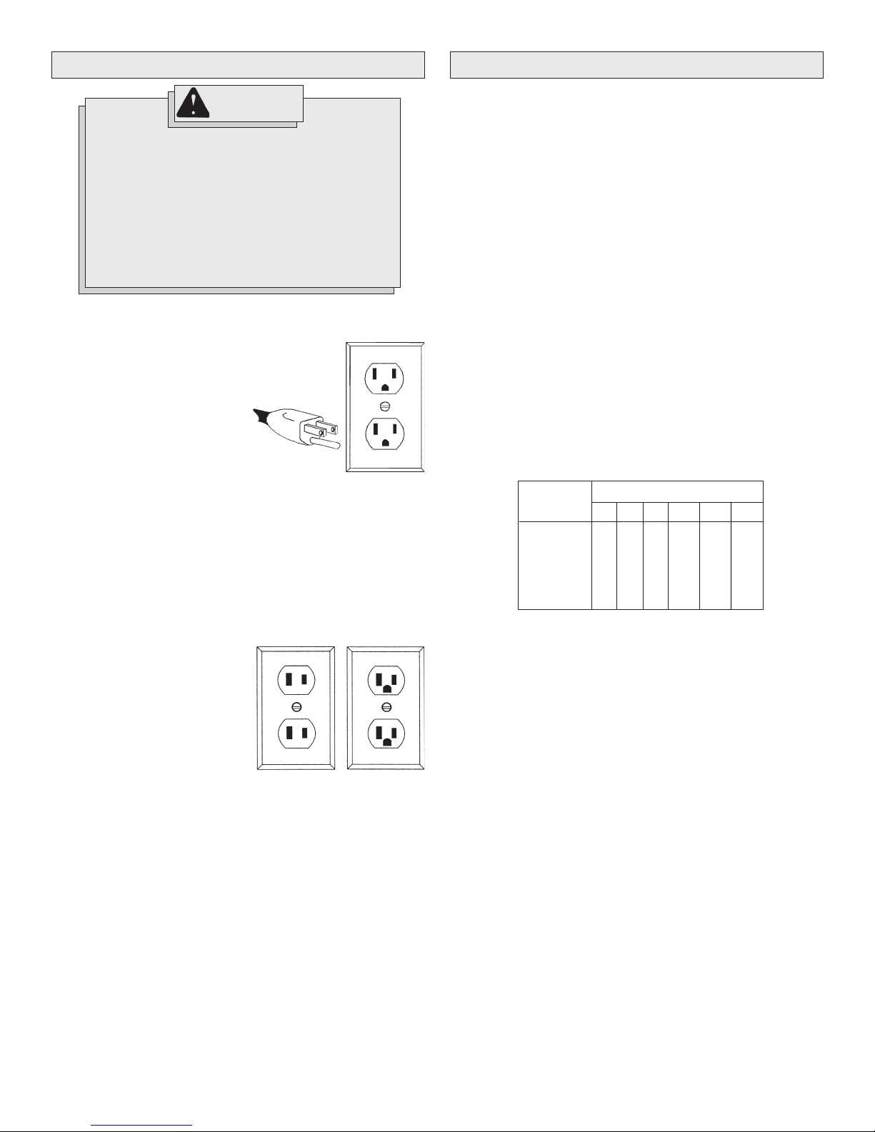
Grounded tools require a three wire extension cord. Double insulated
tools can use either a two or three wire extension cord. As the distance
from the supply outlet increases, you must use a heavier gauge extension cord. Using extension cords with inadequately sized wire causes a
serious drop in voltage, resulting in loss of power and possible tool
damage. Refer to the table shown to determine the required minimum
wire size.
The smaller the gauge number of the wire, the greater the capacity of the
cord. For example, a 14 gauge cord can carry a higher current than a 16
gauge cord. When using more than one extension cord to make up the
total length, be sure each cord contains at least the minimum wire size
required. If you are using one extension cord for more than one tool, add
the nameplate amperes and use the sum to determine the required minimum wire size.
Grounded Tools:
Tools with Three Prong Plugs
Tools marked “Grounding Required”
have a three wire cord and three
prong grounding plug. The plug must
be connected to a properly grounded
outlet (See Figure A). If the tool should
electrically malfunction or break
down, grounding provides a low resistance path to carry electricity
away from the user, reducing the risk
of electric shock.
The grounding prong in the plug is connected through the green wire
inside the cord to the grounding system in the tool. The green wire in the
cord must be the only wire connected to the tool's grounding system and
must never be attached to an electrically “live” terminal.
Your tool must be plugged into an appropriate outlet, properly installed
and grounded in accordance with all codes and ordinances. The plug
and outlet should look like those in Figure A.
Double Insulated Tools:
Tools with Two Prong Plugs
Tools marked “Double Insulated” do
not require grounding. They have a
special double insulation system
which satisfies OSHA requirements
and complies with the applicable
standards of Underwriters Laboratories, Inc., the Canadian Standard
Association and the National Electrical Code. Double Insulated tools may
be used in either of the 120 volt outlets shown in Figures B and C.
Fig. A
Fig. B
Fig. C
Guidelines for Using Extension Cords
• If you are using an extension cord outdoors, be sure it is marked
with the suffix “W-A” (“W” in Canada) to indicate that it is acceptable
for outdoor use.
• Be sure your extension cord is properly wired and in good electrical
condition. Always replace a damaged extension cord or have it
repaired by a qualified person before using it.
• Protect your extension cords from sharp objects, excessive heat
and damp or wet areas.
Recommended Minimum Wire Gauge
Nameplate
Amperes
8.1 - 12
12.1 - 15
15.1 - 20
* Based on limiting the line voltage drop to five
volts at 150% of the rated amperes.
for Extension Cords*
25'
0 - 5
5.1 - 8
16
16
14
12
10
Extension Cord Length
100'
50'
16
16
14
12
10
75'
16
14
12
10
10
14
12
10
10
150'
12
10
--
--
--
--
200'
12
--
--
--
--
READ AND SAVE ALL INSTRUCTIONS
FOR FUTURE USE.
page 6
Page 7
TOOL ASSEMBLY
WARNING!
To reduce the risk of injury, always unplug
tool before attaching or removing accessories
or making adjustments. Use only specifically
recommended accessories. Others may be
hazardous.
Mounting the Miter Saw
To prevent the tool from sliding, falling or tipping during operation, the
saw can be mounted to a supporting surface such as a level, sturdy
work table or bench. Position the saw and workbench to allow adequate
room for cross-cutting long workpieces. To mount the saw, insert fasteners through the four holes in the base of the saw.
Installing the Clamp Handle
The clamp handle locks the selected miter angle. The tool is shipped with
the handle unassembled. To install the handle, thread it clockwise into
the tool. To tighten the handle and lock the angle, turn the handle clockwise. To loosen and unlock, turn it counterclockwise.
Installing Dust Bag or Vacuum Hose
A dust bag is provided to collect sawdust. To install the dust bag, push
the dust bag onto the dust ejection port. This port is also designed to
accept a standard workshop vacuum hose. To collect sawdust directly
into a vacuum cleaner, attach the vacuum cleaner hose to the dust
ejection port and turn it on before cutting.
Raising and Lowering the Saw Head
The saw head locks down for transporting and storing the tool. The tool
is shipped with the saw head locked down. To unlock it, press and hold
down the saw head and simultaneously pull out the lock pin. To lock the
saw head, press and hold down the saw head and then push in the lock
pin.
Locking and Unlocking the The Sliding Mechanism
Lock the sliding mechanism to transport and store the tool. To unlock it,
loosen the slide rail lock by turning it counterclockwise. To lock it, tighten
the slide rail lock by turning it clockwise. Always lock the sliding mechanism before transporting the saw.
Lock-Off
There is a hole in the trigger through which a padlock will fit to lock the
tool when it is not in use. Use a padlock with a 1/4" shackle and always
unplug the tool before installing it (padlock not supplied with tool).
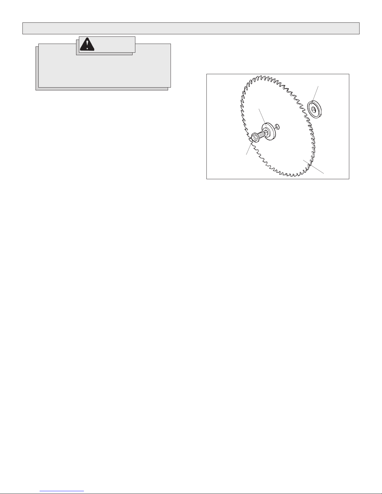
Installing and Changing Blades (Fig. 1)
MILWAUKEE offers a full line of carbide-tipped Miter Saw blades. Always use clean, sharp blades because dull blades tend to overload the
tool, bind and cause pinching. Use only 10" blades rated at least 5500 RPM.
Fig. 1
Outer flange
Blade screw
1. To install a blade, unplug the tool.
2. Raise the saw head.
3. Loosen (do not remove) the two screws on the blade screw guard
counterclockwise.
4. Rotate blade screw guard to expose blade screw.
5. Press in the spindle lock and rotate the spindle until the lock engages.
6. Use the wrench supplied with the tool to loosen and remove the lefthand thread blade screw clockwise (wrench is stored behind the
right fence in wrench holder).
7. Lift and hold up the lower guard.
8. Remove the outer blade flange, blade (if present), and the inner
blade flange. Wipe the flanges and spindle to remove dust and
debris.
9. Install the inner blade flange as shown.
10. Match the arrow on the blade with the arrow on the tool casting.
Install the selected blade by sliding the blade between the gap in the
fence and then lifting the blade up to the spindle.
11. Install the outer blade flange.
12. Press in the spindle lock and rotate the blade until lock engages
while replacing and securely tightening the blade screw counterclockwise with supplied wrench.
13. Rotate the blade screw guard into position and securely tighten the
two screws clockwise. Return the wrench to the wrench holder.
14. Lower the saw head and check the clearance between the blade
and the turntable. The blade should rotate freely.
NOTE: If you are installing the blade for the first time, be aware that
kerf plates (which come uncut) need to be cut before use. See
"Cutting the Kerf Plate Slot".
Inner flange
Blade
A Note About Kerf Plates
The purpose of the kerf plate is to eliminate tear-out (splintering along the
cut) by providing edge support for the workpiece. Because saw blades
can vary in width, to get the best possible edge support and alignment
and to reduce tear-out, each blade (or width of blade) should have its
own kerf plate.
page 7
Page 8
OPERATION
WARNING!
To reduce the risk of injury, wear safety goggles
or glasses with side shields. Always wait for the
blade to stop completely and unplug the tool
before changing accessories or making adjustments. Do not defeat the guards.
Collecting Dust
For dust collection, MILWAUKEE recommends using either Dust Bag No.
48-09-1025 or a MILWAUKEE Vacuum Cleaner. The dust tube is designed to accept a standard vacuum hose and swivels for convenience.
Using Face Boards
There are face board mounting holes in the fences for attaching face
boards. Face boards place distance between the fence and the
workpiece, providing improved support for some workpieces. For example, as the width of the face board increases, the height of the
workpiece which can be cut increases slightly (but the width capacity
decreases slightly). Similarly, if you place a face board on the saw table
and place a workpiece on top of the face board, you can cut a workpiece
with greater width (but with less height).
Guards
The tool is shipped with both the upper and lower guard installed. The
lower guard should cover the blade when the saw head is up and it
should open automatically as the saw head is lowered into the workpiece.
If the lower guard appears loose or if it does not move to cover the blade
when the saw head is up, take the saw to an authorized service center
for repairs. Do not attempt to open the guard further than the automatic
action permits. The tool is designed so that when the guard is opened
with the saw head in the up position, the saw head cannot be lowered.
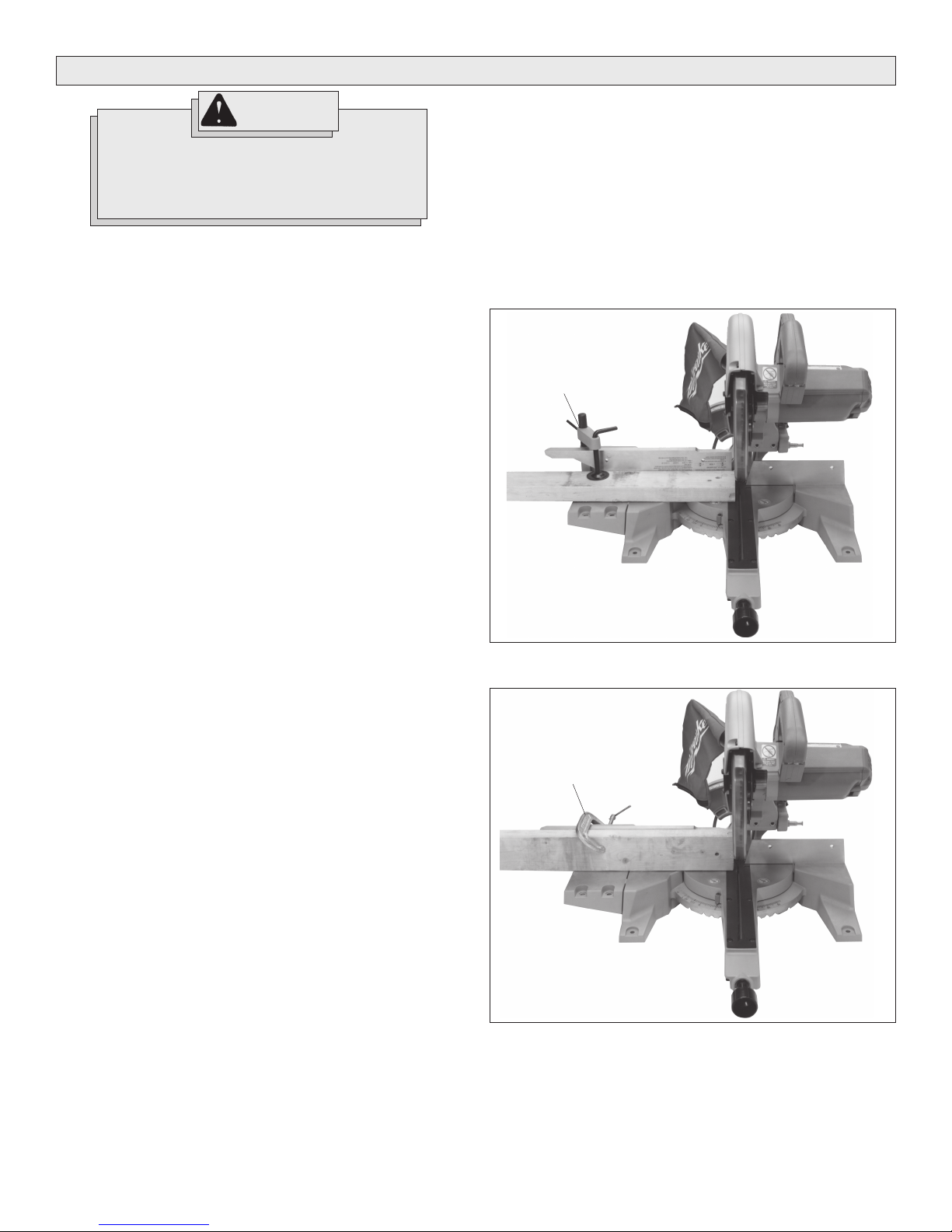
Support the Workpiece Properly (Fig. 2 & 3)
Always support the workpiece during operation. Otherwise, the
workpiece may pull up and into the saw. While there are many ways to
support and secure workpieces, MILWAUKEE advises using one of the
following three methods.
1. Use the Fence: Align the workpiece flush against the fence as
shown to provide a straight path for the saw blade. This will help
eliminate the tendency for the blade teeth to bind. The fence can be
used as a support for miter, bevel and compound cuts.
2. Use Vise No. 49-52-0310: Clamp the workpiece to the base using
the MILWAUKEE vise (Fig. 2). The vise fits into the slot on the back
of the left fence.
Fig. 2
Vise
Select the Workpiece Carefully
Be cautious of pitchy, knotty, wet or warped workpieces. These materials are likely to create pinching conditions. Workpieces that bow and
pinch may result in kick back. Inspect for and remove nails before cutting. Always keep blades clean and sharp; otherwise the blade produces a narrow kerf and is likely to be pinched by the workpiece. This
tool is not recommended for cutting ferrous metals such as iron and
steel. See Applications for a more complete list of materials.
3. Use a C-clamp: Clamp the workpiece to the fence with a C-clamp
(Fig. 3).
Fig. 3
C-clamp
Support of Longer Workpieces
Longer workpieces need support along their length. If you are using the
saw on a level work bench, prop up the workpiece with a small piece of
2x4 on its edge. (The saw base surface is 3 1/2" (the width of a 2x4)
from the bottom of the saw feet.) There are also many aftermarket work
tables specifically designed for miter saws that provide supports for all
types of workpieces.
page 8
Page 9
Adjusting the Miter Angle
®
The miter mechanism on the MILWAUKEE Magnum
Slide Compound
Miter Saw has detent settings for commonly cut angles (0°, 15°, 22.5°
30°, and 45°). These detents make for quick, accurate set up of common
angles. In addition to the spring-loaded detents there is also a detent
override. The detent override, when engaged, allows the turntable to
smoothly rotate to any miter angle. The turntable can be easily locked at
any miter angle. The detent override is especially useful when making
small adjustments near 0°, 15°, 22.5° 30°, and 45°.
The saw cuts miter angles from 51° on the left to 59° on the right. Angle
markings appear on the scale that runs along the perimeter of the base.
1. To select a positive angle stop, loosen the clamp handle.
Pull the detente override lever and rotate the turntable to the desired
angle.
Tighten the clamp handle.
2. To select other angles, use the override mechanism, which allows
quick and accurate adjustments at any angle.
Pull up on the detent override lever and lock it by pushing in the
detent override lock.
Rotate the turntable to the desired angle.
Tighten the clamp handle securely clockwise.
Adjusting the Bevel Angle
The bevel mechanism has two positive sping-loaded stops: one at 0°
and one at 45°. The mechanism can be adjusted to any angle in between
by using the bevel angle scale. The bevel mechanism also has several
degrees of overtravel on both the left and right; the saw can be adjusted
to 48° on the left and to negative 3° on the right. To obtain the overtravel,
apply several pounds of force on the saw handle to override the springloaded stops. Do not attempt to exceed the stated overtravel.
1. To adjust the bevel angle, place one hand on the front handle for
better control. Using the other hand, loosen the bevel adjustment
lever counterclockwise
2. Pull or push the saw handle to desired position, using the bevel
angle scale as a guide.
3. Tighten the bevel adjustment lever clockwise securely.
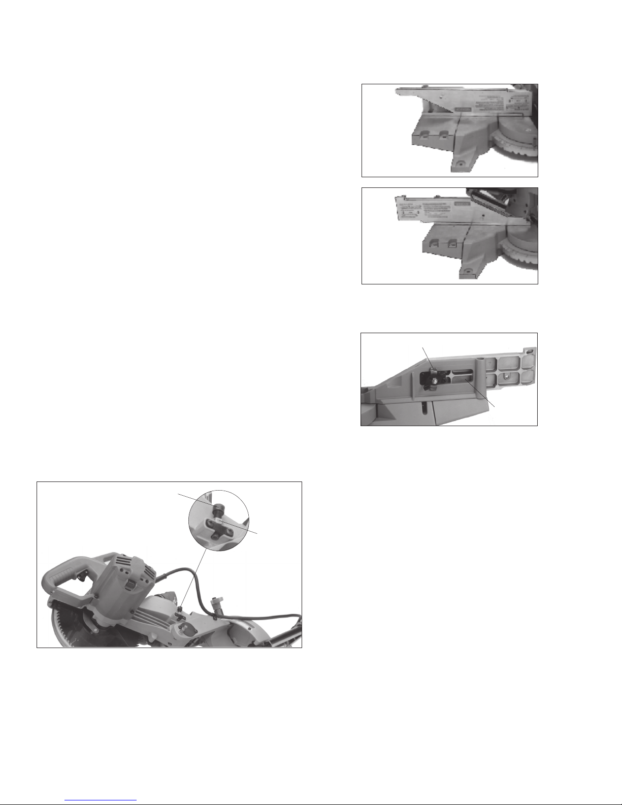
Adjusting the Depth of Cut (Fig. 4)
A hex cap screw with a lock nut controls the depth of cut. This cut can
be adjusted when cutting grooves, rabbets, or other operations
Fig. 4
Socket
head cap
screw
locknut
Using the Flip Fence (Fig. 5, 6, & 7)
The quick-change flip fence can be positioned for simple miter cuts
(Fig. 5) and for bevel and compound cuts (Fig. 6). This helps to provide
superior support for both types of cuts.
Fig. 5
For miter cuts
Fig. 6
For bevel and
compound cuts
1. To adjust the fence, loosen the fence lock lever (counterclockwise)
(Fig. 7). When the fence lock lever is parallel with the fence slot, pull
the fence away from the saw. A firm detent must be overridden to
accomplish this.
Fig. 7
Fence lock lever
Fence slot
2. Position the fence for the desired cut. Always position the fence
properly for maximum work support.
3. With the fence lock lever parallel to the fence, insert the fence lock
lever through the fence slot. Turn the fence lock lever clockwise to
secure the fence to the tool.
NOTE: The clamp on the mechanism must be rotated to a vertical
position, 90° to the slot. This position is required for proper clamping.
Starting and Stopping the Tool
Always hold the handle firmly because the starting and stopping action
of the motor may cause the handle to move up or down slightly. Always
secure the turntable by tightening the clamp handle when setting miter
angles. Always make sure the spindle lock is released so the blade is
free to rotate.
1. To start the motor, pull the trigger.
2. To stop the motor, release the trigger.
1. Unplug the tool.
2. Loosen the lock nut by turning counterclockwise.
3. To set the saw for maximum depth of cut, unscrew the hex cap
screw so that it doesn't extend from the bottom of the saw arm.
To limit the depth of cut, screw the hex cap screw through the saw
arm. The more the screw is driven through the shallower the cut is.
4. Securely tighten the lock nut.
5. Make a sample cut and adjust as necessary.
page 9
Page 10
WARNING!
To reduce the risk of injury, do not rely on the
brake as a safety feature. Always wait until the
blade stops completely before allowing anything near the blade.
Electric Brake
The electric brake engages when the trigger is released, causing the
blade to stop and allowing you to proceed with your work. Generally the
saw blade stops in four to five seconds. However, there may be a delay
between the time the trigger is released and the time the brake engages.
Occasionally the brake may miss completely. If the brake misses frequently, the saw needs servicing by an authorized MILWAUKEE service station. The brake is not a substitute for the guards, so it is essential
to always wait for the blade to stop completely before removing the
blade from the kerf. The correct brush grade must be used for proper
operation of the brake. Use only identical MILWAUKEE replacement
brushes when servicing the tool.
Cutting the Kerf Plate Slot
The tool is shipped with the kerf plate installed; never attempt to make a
cut without the plate installed. The kerf plate is NOT factory-cut, so the
first cut you make with the tool will be to create a kerf slot. The angle of
the kerf slot for compound cuts is different than that for miter cuts.
Therefore, it is necessary to cut new kerf slots for each type of angle.
Generally, it is best to cut a kerf slot before cutting a workpiece.
When cutting a kerf slot, be sure to use the blade you intend to use for
your work since blades have different widths that affect the kerf. When
changing from a thick blade to a thinner one, you may want to purchase
a new kerf plate and cut a new kerf slot. Also, bevel cuts require a
different kerf slot than miter cuts, so always be sure to cut a new slot for
bevel cuts. Cut the kerf slot following the procedure below.
1. Make sure that the slide rail lock is loose and that the saw head
moves freely back and forth on the slide rails.
2. Raise saw head and pull it out OVER the kerf plate WITHOUT cutting.
3. Start the motor. Wait a few seconds for the blade to reach full
speed.
4. Press down on the saw head. To help prevent damaging the kerf
plate, gently and slowly lower the saw head to the full depth of cut
(the point where the saw head will not lower any further). When the
cut is complete, release the trigger. WAIT FOR THE BLADE TO STOP
COMPLETELY before gently raising the saw head.
5. Push saw through the cut.
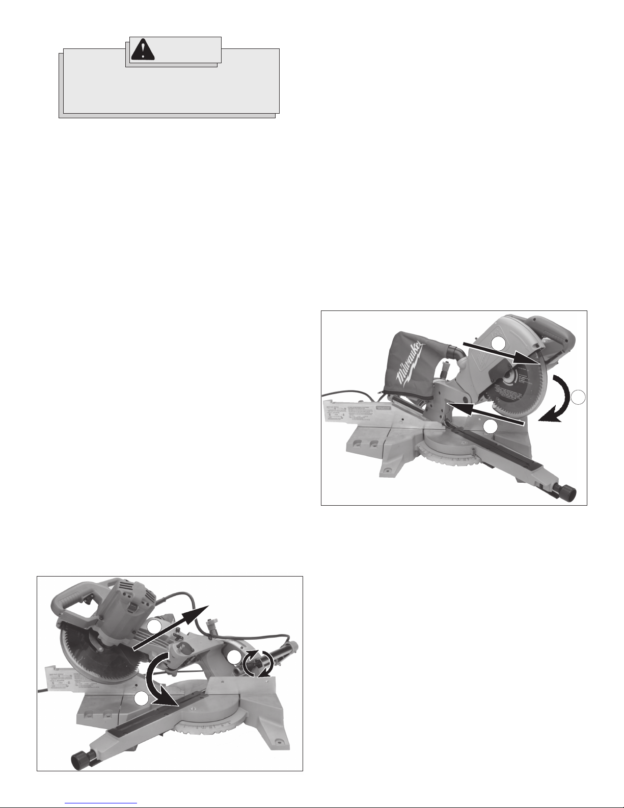
Making a Chop Cut (Fig. 8)
The Magnum® Slide Compound Miter saw can be used to make chop cuts
(cuts not requiring the use of the slide mechanism). Cut workpieces with
chop cuts whenever possible. A chop cut is always faster and easier to
make than a sliding cut.
Fig. 8
1
2
1. Slide the saw head back on the slide rails so that the blade is closest
to the fence (1).
2. Tighten the slide rail lock (2).
3. Plug in the tool. Raise the saw head completely.
4. Select the desired angles following the steps in "Adjusting the Miter
Angle" and "Adjusting the Bevel Angle".
5. Place the workpiece on the turntable and line up the cut.
6. Support the workpiece using any of the methods described in "Support the Workpiece Properly".
7. Start the motor. Wait a few seconds for the blade to reach full
speed. Then gently lower the saw head into the workpiece all the
way through the cut (3).
8. Always allow the saw to do the work. Forcing the tool may stall or
overheat the motor.
9. After the cut is complete, release the trigger and wait for the blade
to stop completely. Then gently raise the saw head and remove the
workpiece. Always unplug the tool before retrieving loose cut-off
pieces from inside the guard area.
Making a Sliding Cut (Fig. 9)
Cut workpieces with chop cuts whenever possible. A chop cut is always faster and easier to make than a sliding cut. Cut wider workpieces
using the sliding mechanism.
Fig. 9
1
2
3
1. Make sure that the slide rail lock is loose and that the saw head
moves freely back and forth on the slide rails.
2. Select the desired angle following the steps in "Adjusting the Miter
Angle" and "Adjusting the Bevel Angle".
3. Place the workpiece on the turntable and line up the cut.
4. Raise saw head and pull it out OVER the workpiece WITHOUT cutting (1).
5. Start the motor. Wait a few seconds for the blade to reach full
speed.
6. Press down on saw head (2).
7. Push saw through the cut (3).
8. After the cut is complete, release the trigger and wait for the blade
to stop completely. Then gently raise the saw head and remove the
workpiece. Always unplug the tool before retrieving loose cut-off
pieces from inside the guard area.
3
page 10
Page 11
APPLICATIONS
Recommended Materials and Applications
The following materials can be cut with the slide compound miter saw.
There are many types of saw blades available. Always use the proper
blade for the particular material and application.
Wood
solid wood, plywood, particle board, MDF (medium density fiberboard), HDF (high density fiberboard), melamine laminated particle
board, formica laminates, hardboard (masonite).
Plastics
PVC, CPVC, ABS, solid surfacing materials (such as Corian®), and
other plastic materials.
Nonferrous Metals
aluminum, brass, copper, and other non-ferrous materials.
WARNING!
Do not cut stone, brick, concrete, or ferrous
metals (iron, steel, stainless steel, or alloys of
these metals) with this saw.
Do not use abrasive wheels with this saw.
Dust created by cutting these materials and/or
using abrasive cut-off wheels can jam the blade
guard and possibly cause personal injury.
Cutting Non-Square Materials
Cutting Round (Cylindrical) Materials
"V" shaped blocks can be used to support round materials like closet rod
and plastic pipe.
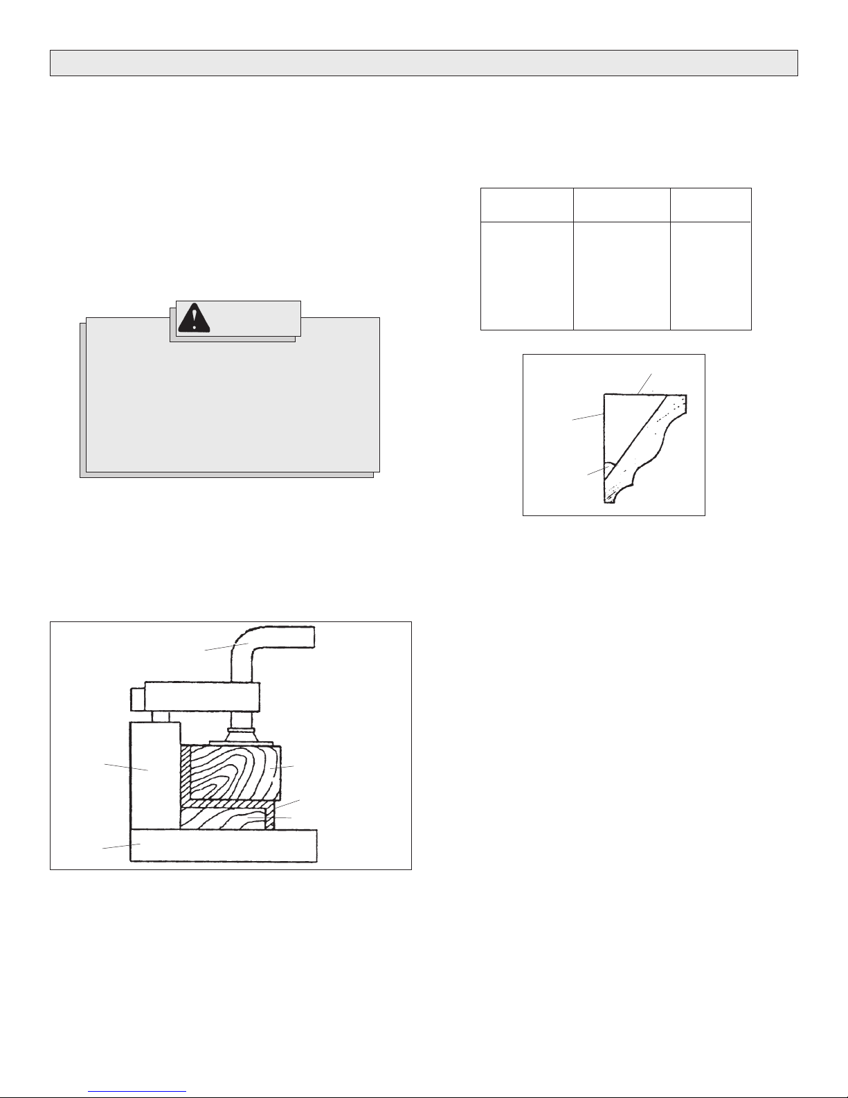
Cutting Compound Miters (Fig. 11)
The chart below identifies miter and bevel settings for various types of
crown molding for 90° corners. Note that these are ideal settings and
may vary because many moldings have slightly different spring angles
and some walls are not perfectly square. Fig. 11 illustrates the relationship between the spring angle, the ceiling, the wall and the molding.
Type of Crown
(spring angle)
30°
35°
38°
40°
45°
52°
* Wood is positioned flat on the miter saw table.
Fig. 11
Wall
Spring
angle
Miter
(angle of table)
26.6°
29.8°
31.6°
32.7°
35.3°
38.2°
Ceiling
Bevel
(tilt of blade)
37.8°
35.4°
33.9°
32.8°
30°
25.8°
Aluminum Sash and Other Channel Type and Materials (Fig. 10)
Aluminum sash material can be supported with blocks to prevent it from
deforming while it is being cut (Fig. 10).
Fig. 10
Fence
Base
Clamp
Wood support block
Aluminum material
Wood support block
page 11
Page 12
MAINTENANCE
ACCESSORIES
WARNING!
To reduce the risk of injury, always unplug
your tool before performing any maintenance.
Never disassemble the tool or try to do any
rewiring on the tool's electrical system. Contact
a MILWAUKEE service facility for ALL repairs.
Maintaining Tools
Keep your tool in good repair by adopting a regular maintenance program. Before use, examine the general condition of your tool. Inspect
guards, switches, tool cord set and extension cord for damage. Check
for loose screws, misalignment, binding of moving parts, improper mounting, broken parts and any other condition that may affect its safe operation. If abnormal noise or vibration occurs, turn the tool off immediately
and have the problem corrected before further use. Do not use a damaged tool. Tag damaged tools “DO NOT USE” until repaired
(see “Repairs”).
Under normal conditions, relubrication is not necessary until the motor
brushes need to be replaced. After six months to one year, depending on
use, return your tool to the nearest MILWAUKEE service facility for the
following:
• Lubrication
• Brush inspection and replacement
• Mechanical inspection and cleaning (gears, spindles, bearings,
housing, etc.)
• Electrical inspection (switch, cord, armature, etc.)
• Testing to assure proper mechanical and electrical operation
WARNING!
To reduce the risk of injury, always unplug the
tool before attaching or removing accessories.
Use only specifically recommended accessories. Others may be hazardous.
For a complete listing of accessories refer to your MILWAUKEE Electric
Tool catalog. To obtain a catalog, contact your local distributor or a
service center listed on the back cover of this operator’s manual.
Vise
Cat. No. 49-52-0310
Secures workpiece to the miter saw base.
Dust Bag
Cat. No. 48-09-1025
Collects dust to help keep the work area clean.
Kerf Plate
Cat. No. 49-52-0405
Same as supplied with the tool. Use a new kerf plate when changing
from a thick to a thinner blade or if the kerf slot enlarges due to blade
deflection.
Guide Rod Assembly
Cat. No. 49-52-0110
Fasten guide rods to the miter saw base to provide added support for
longer workpieces.
Cleaning
Clean dust and debris from vents. Keep the tool handles clean, dry and
free of oil or grease. Use only mild soap and a damp cloth to clean your
tool since certain cleaning agents and solvents are harmful to plastics
and other insulated parts. Some of these include: gasoline, turpentine,
lacquer thinner, paint thinner, chlorinated cleaning solvents, ammonia
and household detergents containing ammonia. Never use flammable or
combustible solvents around tools.
WARNING!
To reduce the risk of injury, electric shock and
damage to the tool, never immerse your tool in
liquid or allow a liquid to flow inside the tool.
Repairs and Adjustments
The slide compound miter saw is shipped with the fences aligned and
square and the bevel adjustment mechanism calibrated to the bevel
scale. The fences and bevel adjustment mechanism can be knocked out
of alignment if your saw is dropped or is severely knocked. If your saw
is out of alignment, take it to a MILWAUKEE service center for repair.
page 12
WARRANTY
Every MILWAUKEE product is warranted to be free from defects in
material and workmanship. MILWAUKEE will repair or replace any product
which examination proves to be defective in material or workmanship.
Limitations: This warranty does not cover: 1) repairs made or attempted by other than MILWAUKEE or MILWAUKEE Authorized Service
Station personnel; 2) normal wear and tear; 3) abuse; 4) misuse;
5) improper maintenance; 6) continued use after partial failure; 7) tools
that have been modified; or product used with an improper accessory.
Battery Packs are warranted for one (1) year from the date of purchase.
Should a problem develop, return the complete product to any
MILWAUKEE Factory Service Center or MILWAUKEE Authorized Service Station, freight prepaid and insured. If inspection shows the problem is caused by a defect in material or workmanship, all repairs or a
replacement will be made at no charge and the product will be returned,
transportation prepaid. No other warranty, written or verbal, is authorized.
THE REPAIR AND REPLACEMENT REMEDIES DESCRIBED HEREIN ARE
EXCLUSIVE. IN NO EVENT SHALL MILWAUKEE BE LIABLE FOR ANY
INCIDENTAL, SPECIAL, OR CONSEQUENTIAL DAMAGES, INCLUDING
LOSS OF PROFITS.
THIS WARRANTY IS IN LIEU OF ALL OTHER WARRANTIES, EXPRESSED OR
IMPLIED WHETHER FOR MERCHANTABILITY OR FITNESS FOR PARTICULAR
USE OR PURPOSE.
This warranty gives you specific legal rights. You may also have
other rights that vary from state to state. In those states that do not
allow the exclusion of implied warranties or limitations of incidental or consequential damages, the above limitations or exclusions
may not apply to you.
Page 13
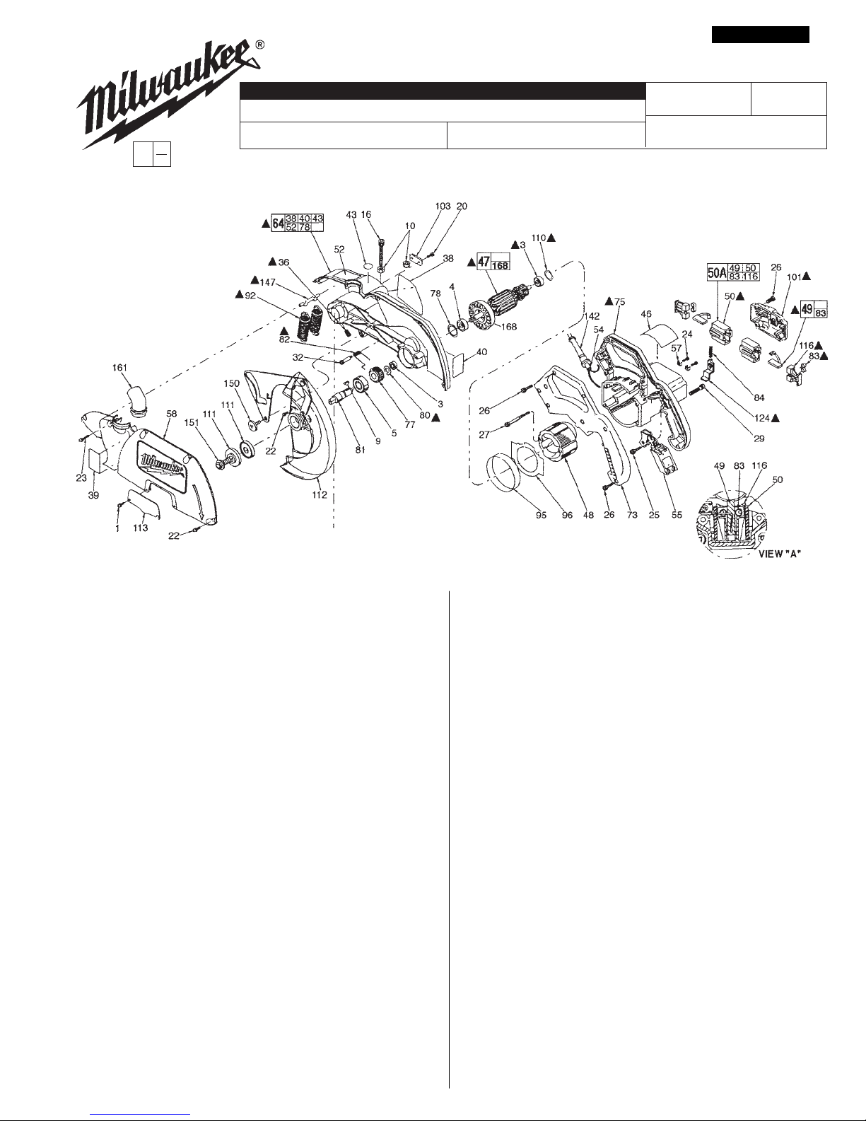
SPECIFY CATALOG NO. AND SERIAL NO. WHEN ORDERING PARTS
EXAMPLE:
00
Component Parts (Small #) Are Included
0
When Ordering The Assembly (Large #).
CATALOG NO.
SERVICE PARTS LIST
SLIDING COMPOUND MITER SAW
6497 882C
STARTING
SERIAL NO.
PAGE 1 OF 2
BULLETIN NO.
54-40-6577
REVISED BULLETIN
54-40-6576
WIRING INSTRUCTION
DATE
July 2004
58-01-1350
=Part number change from
previous service parts list.
FIG. PART NO. DESCRIPTION OF PART NO. REQ.
1 06-82-5560 10-24 x 1/2 Pan Hd. Slt. Taptite T-25 (2)
3 02-04-0845 8 x 22 x 7 Ball Bearing (2 )
4 02-04-1229 12 x 32 x 10 Ball Bearing (1 )
5 02-04-2040 20 x 47 x 14 Ball Bearing (1 )
9 06-42-2400 Woodruff Key (1)
10 06-55-2500 3/8-16 Hex Nut (2 )
16 06-75-4697 3/8-16 x 1-1/2 Cap Machine Screw (1 )
20 06-82-5314 10-24 x 1/2 Pan Hd. Taptite T-25 (2)
22 06-82-5411 10-24 x 5/8 Pan Hd. Slt. Taptite T-25 (8)
23 06-82-5574 10-24 x 7/8 Pan Hd. Slt. Taptite T-25 (1)
24 06-82-7212 4-20 x 1/4 Pan Hd. Plastite T-10 (2)
25 06-82-7226 6-19 x 5/16 Pan Hd. Plastite T-15 (1)
26 06-82-7270 8-16 x 5/8 Pan Hd. Slt. Plastite T-20 (12)
27 06-82-7453 8-16 x 2-1/4 Pan Hd. Slt. Plastite T-20 (2)
29 06-82-9024 10-24 x 1-3/4 Pan Hd. Slt. Tapt. Sems T-25 (4)
32 06-82-9690 Shoulder Screw (1)
36 06-83-3150 5/16-18 x 1/2 Set Screw Hex Socket (2 )
38 10-15-0601 Trilingual Label (1)
39 10-15-1510 Satisfaction Label (1)
40 10-15-9450 Warning Label (1)
43 10-20-1210 Warning (Rain) Label (1)
46 12-20-0810 Service Nameplate Kit (1)
47 16-70-0420 Armature (1)
48 18-70-0420 Field (1)
49 22-18-0387 Carbon Brush Assembly (2 )
50 22-20-0800 Brush Tube (2)
50A 22-20-0802 Brush Tube Assembly (2)
52 10-15-0615 Label - 3 step sliding motion (1 )
54 22-64-3210 Cord (1)
55 23-66-2035 Switch (1)
57 23-74-1150 Terminal (2)
58 25-20-1331 Upper Guard Cover (1 )
FIG. PART NO. DESCRIPTION OF PART NO. REQ.
64 28-14-2275 Upper Guard / Gear Case Assembly (1)
73 31-44-1725 Handle Half (1)
75 31-50-1013 Motor Housing (1)
77 32-75-3350 Gear (1)
78 34-40-1375 1-1/4 Dia. O-Ring (1)
80 34-60-2560 Retaining Ring (1)
81 38-50-5840 Spindle (1)
82 40-50-1205 Lower Guard Return Spring (1 )
83 40-50-8160 Coil Spring (2)
84 40-50-8170 Spring (Spindle Lock) (1)
92 40-50-8680 Return Spring (2 )
95 42-14-0350 Baffle (1)
96 42-14-0355 Baffle (1)
99 42-50-0281 Cam Link (1)
101 42-92-0890 End Cover (1)
103 42-92-1070 Nut Retaining Cover (1)
110 45-88-0577 Wave Washer (1)
111 43-34-0720 Blade Flange (2)
112 43-54-0735 Lower Guard Assembly (1)
113 43-54-0740 Blade Screw Guard (1)
116 43-72-0180 Spring Holder (2)
124 44-10-0310 Locking Lever ( 1)
142 44-76-0210 Cord Protector (1 )
147 44-94-0410 Spring Hanger Rod (1)
150 45-04-0850 Shoulder Screw (1)
151 45-04-0860 Blade Screw (1)
161 45-76-0331 Dust Tube (1)
168 22-84-0850 Fan (1)
MILWAUKEE ELECTRIC TOOL CORPORATION
13135 W. LISBON RD., BROOKFIELD, WI 53005
Drwg. 2
Page 14
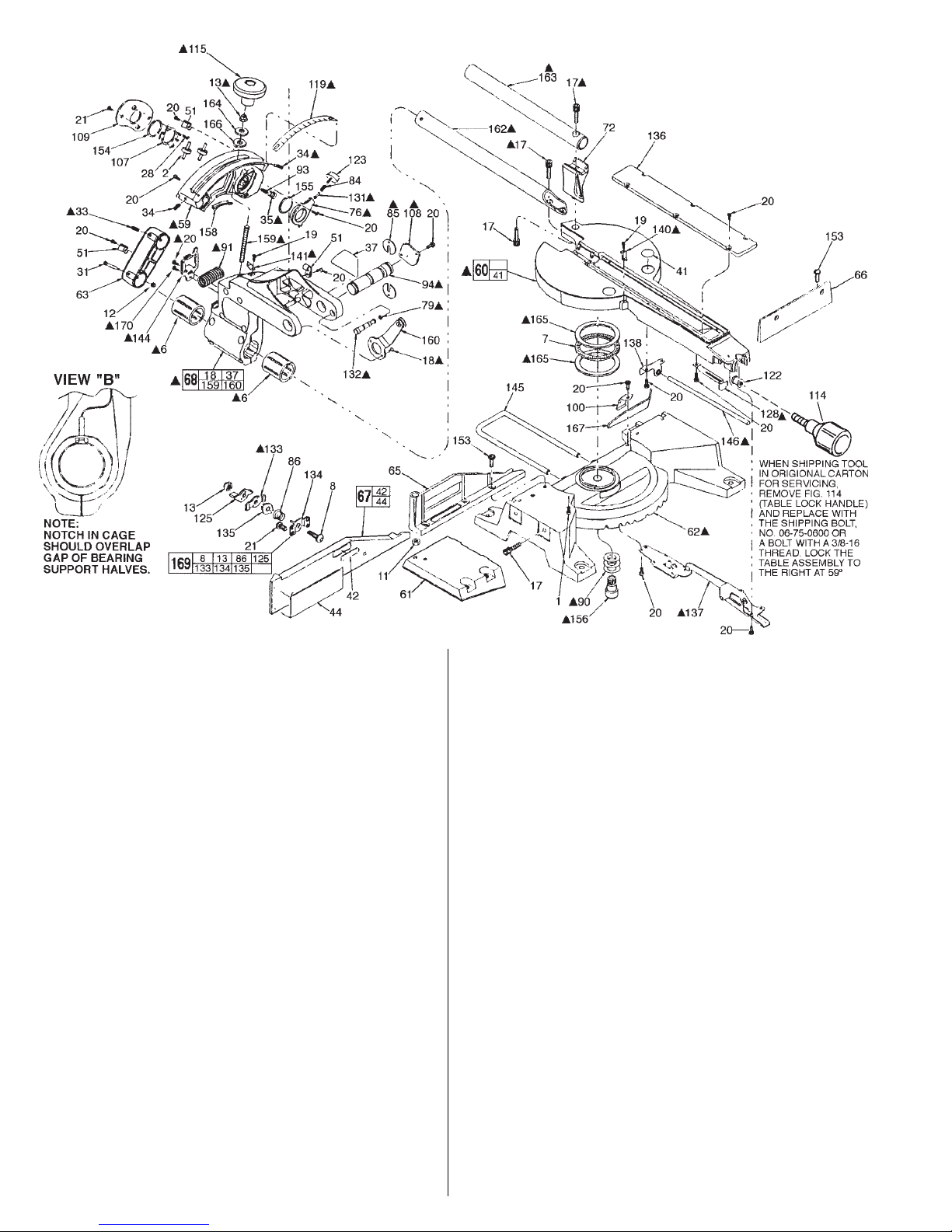
FIG. PART NO. DESCRIPTION OF PART NO. REQ.
1 06-82-5560 10-24 x 1/2 Pan Hd. Slt. Taptite T-25 (1)
2 02-80-6100 Bearing Shaft Assembly ( 2)
6 02-40-1060 Linear Ball Bearing (2)
7 02-80-0130 Needle Thrust Bearing (1)
8 06-10-1153 5/16-18 x 1-1/4 Carriage Bolt (1 )
11 06-55-2710 7/16-14 Hex Nut (1 )
12 06-57-1100 10-24 Locknut ( 1)
13 06-57-5045 5/16-18 Locknut (2 )
17 06-81-3172 5/16-18 x 1 Hex Drive Taptite Screw ( 6 )
18 06-82-3792 8-32 x 3/8 Flat Hd. Taptite T-15 (2)
19 06-82-5270 6-32 x 1/4 Pan Hd. Slt. Taptite T-15 (2)
20 06-82-5314 10-24 x 1/2 Pan Hd. Slt. Taptite T-25 (26)
21 06-82-5338 1/4-20 x 1/2 Pan Hd. Taptite T-30 (4 )
28 06-82-8844 8-32 x 3/8 Pan Hd. Machine Screw ( 2 )
31 06-82-9680 1/4 x 1-1/2 Cap Shoulder Screw ( 1)
33 06-83-6035 1/4-20 x 3/8 Hex Socket Set Screw ( 2)
34 06-83-3125 1/4-20 x 3/4 Hex Socket Set Screw ( 2)
35 06-83-3126 3/8-16 x 3/8 Hex Socket Set Screw ( 1)
37 10-15-0600 Trilingual Label (1)
41 10-15-9460 Warning Label ( 2)
42 10-15-9480 Warning Label ( 1)
44 10-20-1250 Label (1)
51 22-38-0150 Cabl e Clamp (3)
59 28-04-0360 Torque Arm (1 )
60 28-06-1055 Table Assembly (1)
61 28-06-1060 Base Extension (1)
62 28-06-1080 Base ( 1)
63 28-12-0150 End Cap (1)
65 28-35-0020 Left Fence (1 )
66 28-35-0030 Right Fence (1)
67 28-35-0040 Adjustable Fence (1)
68 28-90-0271 Bearing Support Assembly (1 )
72 28-90-0281 Auxiliary Tube Support (1 )
76 31-58-0200 Traverse Lock (1)
79 34-40-3000 O-Ring (1)
84 40-50-8170 Spring (1)
85 40-50-8190 Disc Spring (2)
86 40-50-8610 Conical Spring (1)
90 40-50-8620 Belleville Spring (3)
91 40-50-8660 Bevel Overtravel Spring ( 1)
93 40-50-8710 Auxiliary Bearing Spring (1)
94 42-12-0170 Axle (1)
100 42-70-5141 Blade Wrench Clip (1)
FIG. PART NO. DESCRIPTION OF PART NO. REQ.
107 42-92-1085 Bearing Clamp Cover (1)
108 42-92-1090 Axle Cover (1)
109 42-92-1100 Torque Arm Cover (1 )
114 43-62-1052 Table Lock Handle (1)
115 14-34-0205 Adj. Knob Assy. (Incl. 06-55-1985 Hex Nut) (1 )
119 43-82-0150 Bevel Angle Indicator (1)
122 43-84-0860 Hex Insert (1 )
123 43-98-0610 Knob (1)
125 44-10-0330 Fence Clamp Lever (1)
128 44-20-0255 Detent Lock (1)
131 44-60-1095 Traverse Pin (1)
132 44-60-1410 Lock Pin (1)
133 44-66-6060 Clamp Plate (1)
134 44-66-6070 Mounting Plate (1)
135 44-66-6080 Detent Plate (1)
136 44-66-6110 Kerf Plate (1)
137 44-66-6121 Detent Ball Plate Assembly (1)
138 44-66-6170 Locking Plate / Rod Guide (1 )
140 44-72-0010 Miter Scale Pointer (1 )
141 44-72-0110 Bevel Scale Pointer (1 )
144 44-86-0605 Overtravel Spring Retainer (1)
145 44-94-0350 Guide Rod (1 )
146 44-94-0405 Extension Rod (1 )
153 45-04-0910 5/16-18 x 7/8 Pan Hd. Taptite Sems T-30 ( 5)
155 45-06-0559 Seal Kit (1)
156 45-08-0330 Table Shaft (1)
158 45-14-0250 Bearing Support Shim (1)
159 45-58-0333 Bevel Clamping Stud (1)
160 45-60-0611 Cam Roller Support Assembly (1)
162 45-76-0450 Guide Tube (1)
163 45-76-0460 Auxiliary Tube (1)
164 45-88-8460 Vertical Adjustment Washer (1)
165 45-88-8540 Thrust Washer (2)
166 45-88-8805 Nylon Washer ( 1)
167 49-96-6205 Blade Screw Wrench (1)
169 14-46-2060 Clamp Mechanism Kit (1)
170 45-04-0730 10-24 x 1/2" Shoulder Screw ( 1)
•
Page 15

FIG. LUBRICATION
59, 158 Place a light coat of Type "L" Grease, No. 50-08-4230, between Fig. 59 (Torque Arm) and Fig. 158 (Bearing Support Shim).
%%
%
%%
BULLETIN NO. 54-40-6577 July 2004 PAGE 2 OF 2
62, 156 Apply .12 oz. of Type “L” Grease, No. 50-08-4230, under the head of the Fig. 156 (Table Shaft Assembly).
64 Place .50 oz. of Type "Y" Grease, No. 49-08-5270, in the pinion pocket of Fig. 64 (Upper-Guard / Gear Case Assembly).
68 Seal slot between halves of Fig. 68 (Bearing Support Assembly) with Type "B" Grease, No. 49-08-0600.
68, 94 Apply .06 oz. of Type “L” Grease, No. 50-08-4230, to the two .125 wide grooves of Fig. 94 (Axle).
79, 132 After assembling Fig. 79 (O-Ring) onto Fig. 132 (Lock Pin), apply a light coat of Type "L" Grease, No. 50-08-4230.
94, 108 Apply a dab of Type “L” Grease, No. 50-08-4230, to the cover end of Fig. 94 (Axle), Prior to assembly of Fig. 108 (Axle Cover).
133 Apply a thin film of Type “L” Grease, No. 50-08-4230, to both sides of Fig. 133 (Clamp Plate) prior to assembly.
165 Apply a thin film of Type “L” Grease, No. 50-08-4230, to both sides of Fig. 165 (Thrust Washers).
114, 158, 159 Apply a thin film of Type “L” Grease, No. 50-08-4230, to threads of Fig. 114 (Table Lock Handle) and Fig. 159 (Bevel Clamping
FIG. NOTES:
3 Seal of Fig. 3 (Ball Bearing) towards fan of Fig. 47 (Armature).
6 Assemble Fig. 6 (both Linear Ball Bearings) so that the notch in the end of the cage faces out and oriented top dead center.
6, 68, 162 To establish a zero clearance condition between Fig. 6 (Linear Bearing) and Fig. 162 (Guide Tube), apply red locking sealant to
Apply a thin film of type “L” grease, No. 50-08-4230, prior to assembly, to the O.D. of the Fig. 156 (Table Shaft Assembly) and to
the I.D.of the center bore of the Fig. 62 (Base).
Apply a thin film of Type “L” Grease, No. 50-08-4230, to the O.D. of Fig.94 (Axle) - (Not between the two locating grooves),
and to the I.D. of the two pivoting hubs of Fig. 68 (Bearing Support Assembly) prior to assembly.
Stud) and to Fig. 158 (Bearing Support Shim).
%%
%
%%
(See view "B" for tolerance of orientation).
two threads of the two screws above the bearings and tighten, in Fig. 68 (Bearing Support Assembly), one at a time while
rotating the Bearing Support Assembly, until resistance is felt, then back out screw (1/8 turn max.) until Bearing Support
Assembly rotates freely.
13, 59, 68 To establish proper clearance between Fig. 68 (Bearing Support Assembly) and Fig. 59 (Torque Arm), tighten Fig. 13
17 IMPORTANT: Apply red locking sealant and tighten Fig. 17, the outboard (rear most) screw first to 150 in./lbs. Apply blue locking
18 Apply blue locking sealant to two threads of Fig. 18 (Flat Head Screw) prior to assembly.
20, 144, 170 Apply blue locking sealant to two threads of Fig. 20 (10-24 Pan Hd. Screw) and Fig. 170 (10-24 Shoulder Screw) prior to
33 Replace Fig. 33 (Set Screws) with new whenever servicing. Apply blue locking sealant to two threads prior to assembly.
34 Apply blue locking sealant to two threads of Fig. 34 (Set Screws) prior to setting the 0° and 45° bevel stops.
35 Apply blue locking sealant to two threads of Fig. 35 (Set Screw) prior to assembly.
36, 108 WARNING: Only tighten Fig. 36 (5/16 Set Screws) after assembly of Fig. 108 (Axle Cover).
47 Rotation of Fig. 47 (Armature) is clockwise when viewed from commutator end of motor housing.
47, 75, 110 Place Fig. 110 (Wave Washer) into Fig. 75 (Motor Housing) prior to assembling onto Fig. 47 (Armature).
47, 124 Check Fig. 124 (Locking Lever) for smooth operation and easy engagement of spindle on Fig. 47 (Armature).
49, 101 Brush shunt to be positioned as shown in view "A", so as not to interfer with Fig.101 (End Cover) during assembly.
(5/16 Locknut) while rotating the Bearing Support Assembly until uniform resistance is felt, then back out nut (1/4 turn max.) until
Bearing Support Assembly rotates freely.
sealant and tighten the forward screw to 80 in./lbs.
assembly. After seating screws, back screw #20 out (max. 1/8 turn) until Fig. 144 (Retainer) moves freely side to side.
Check cutting motion for smooth operation of all moving parts.
Check rotating table for smooth operation thru a range of 50° left to 58° right.
Screw closest to Axle Cover is to be tightened first.
50, 116 Fig. 116 (Spring Holder) must be oriented in Fig. 50 (Brush Tube) such that the open end of the spring cavity
is facing the shunt slot in Brush Tube.
58, 92, 147 Before removing Fig. 58 (Upper Guard Cover), unhook Fig. 92 (Return Springs) from Fig. 147.
60, 162 After assembly of Fig. 162 (Guide Tube) to Fig. 60 (Table), parallelism between Guide Tube and Table surface must be ± .15º.
64, 147 Insert short end of Fig. 147 (Spring Rod Hanger) into Fig. 64 (Upper Guard / Gearcase Assembly).
SEE BACK FOR ADDITIONAL NOTES
Page 16
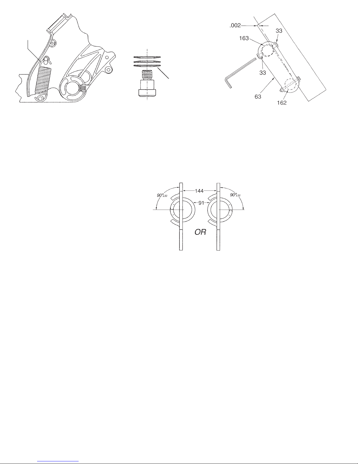
Proper
Orientation
Of Springs
#92 As Shown
Adjust Set Screws #33,
to position Auxiliary Tube
#163, so as to establish a
planer condition of .002
between Auxiliary Tube
and Guide Tube #162
Orientate Belleville
Springs #90 Over
Table Shaft #156
As Shown
76, 131, 163 Insert Fig. 131 (Traverse Pin) into Fig. 76 (Traverse Lock) so that the end with the larger diameter will contact
80 Assemble Fig. 80 (Retaining Ring) with the concave bow of the ring toward the gear.
82, 99 Insert bent leg of Fig. 82 (Spring) into small "L" shaped slot of Fig. 99 (Cam Link) prior to assembling Cam Link to Gear Case.
83, 116 Fig. 83 (Coil Spring) must be oriented in Fig. 116 (Spring Holder) such that the saddle of the Coil Spring is facing
85 Relative orientation of Fig. 85 (Disc Springs)
91, 144 Orientation of Fig. 91 (Bevel Overtravel Spring)
92 Fig. 92 (Return Spring) orientation - Lower hook
119, 141 With Saw Head positioned at the 0° bevel stop, adjust Fig. 119 (Bevel Angle Indicator) so that the 0° mark aligns with
128 To produce a quick disengaging action of Fig. 128 (Detent Lock), apply an outward force at the middle of the part so as to contact
Fig. 163 (Auxiliary Tube) when assembled.
Check operation of Lower Guard mechanism:
A . To verify that Lower Guard freelyretracts and returns to start position, actuate saw as if making a cut.
B. To verify that the Lower Guard Return Spring is functioning properly, retract Lower Guard by hand with saw head up.
When released, the Guard should return to it's start position.
C. To verify Saw Head/Lower Guard Interlock, hold Lower Guard in retracted position and try to lower the Saw Head.
the open end of the Spring Holder.
should be 180° apart - Dimples to engage slots.
and Fig. 144 (Overtravel Spring Retainer)
should be as shown to the right, with end of coil
positioned 90º ±30º to face of retainer.
of Return Spring to be open toward back of tool
as shownabove.
Fig. 141 (Pointer). Then rotate Saw Head to the 45° stop and check to see that Pointer is aligned with the 45° mark.
wall of Fig. 60 (Table Assembly), then secure.
128, 137 Check operation of Fig. 137 (Detent Ball Plate Assembly) for positive locking and disengaging.
140 Check to see that Fig. 140 (Pointer) is lined up with the designated detent markings (45°, 30°, 22-1/2°, 15° and 0° in both directions).
146 Spherical end of Fig. 146 (Extension Rod) to be towards locking plate.
156 Apply blue locking sealant to two threads of Fig. 156 (Table Shaft) prior to assembly. Torque to 30 ft./lbs.
159 Apply blue locking sealant to two threads of Fig. 159 (Threaded Stud) prior to assembly.
Then check operation of Fig. 128 (Detent Lock).
Check angularity limits:
A . Spindle mounting face to base to be 90° ± .22° at 0° bevel angle and
45° ± .22° at 45° bevel angle.
B. Spindle mounting face to kerf plate pocket to be 0° ± .50°.
C. Spindle mounting face to fence to be 90° ± .10°.
After securing fence, spindle axis should be positioned at least 1.920" horizontally from machined surface of fence and, at most,
4.563" vertically from machined surface of table, at 7/16" depth of cut.
Page 17
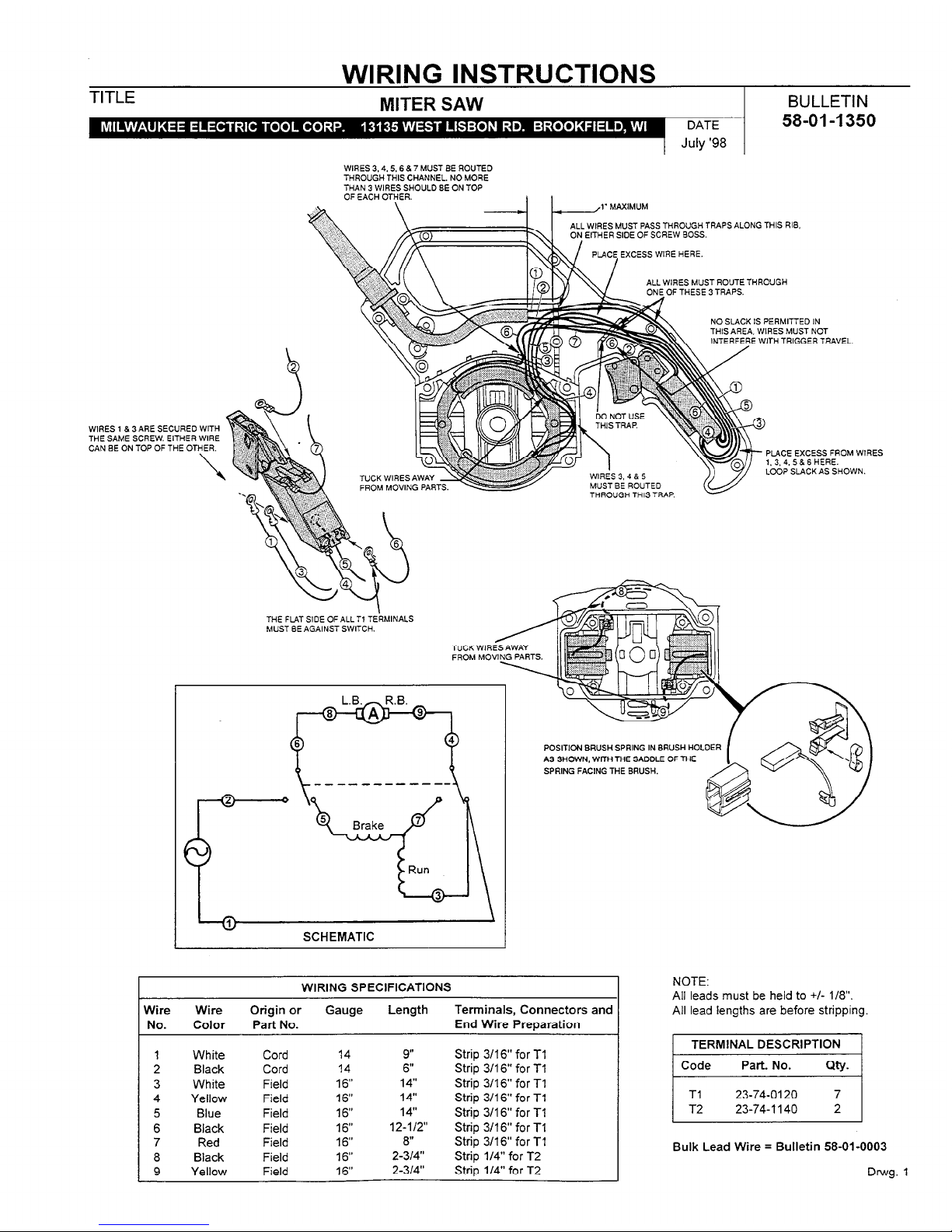
WIRING INSTRUCTIONS
TITLE
MITER SAW
BULLETIN
-44x~l41mL
:
Q.1 rw*o-:, -
DATE
58-01-I 350
July ‘98
WIRES 3.4.5.6 8 7 MUST BE ROUTED
THROUGH THIS CHANNEL. NO MORE
THAN 3 WIRES SHOULD SE ON TOP
ALL WlRES MUST PASS THROUGH TRAPS ALONG THIS RIB
WIRES 1 & 3ARE SECURED WITH
THE SAME SCREW. EITHER WIRE
CAN SE ON TOP OF THE OTHER.
\
r
t
ALL WIRES MUST ROUTE THROUGH
OF THESE 3 TRAPS.
NO SLACK IS PERMIn
TUlq ARFA WlRFR MI
iD IN
:T Nrsr
INTERFERE WITH TRIGGER TRAVEL.
.._.... _~., ..__ ..__. .._.
I--, I
. . ..___.
.-_
FROM MOVING PAR
MUST SE ROUTED
THROUGH THISTRAP.
PLACE EXCESS FROM WIRES
1.3.4. 5 8 6 HERE.
LOOP SLACK AS SHOWN.
MUST SE AGAINST SWITCH.
SCHEMATIC
Wire Wire
No. Color
1 White
2 Black
3 White
4 Yellow
5 Blue
6 Black
7 Red
8 Black
9 Yellow
I
WIRING SPECIFICATIONS
I
Origin or Gauge Length
Part No.
Cord
Cord
Field
Field
Field
Field
Field
Field
Field
14
14
16”
16”
16”
16”
16”
16”
16”
9” Strip 3/16” for Tl
6”
Strip 3116” for Tl
14”
Strip 3/16” for Tl
14”
Strip 3/l 6” for Tl
14”
Strip 3/l 6” for Tl
12-l/2”
Strip 3/16” for Tl
8”
Strip 3116” for Tl
2-314”
Strip l/4” for T2
2-314”
Strip l/4” for T2
Terminals, Connectors and
End Wire Preoaration
NOTE:
All leads must be held to +/- l/8”.
All lead lengths are before stripping.
TERMINAL DESCRIPTION
Code Part. No.
Q-Y.
Tl 23-74-0120 7
T2
23-74-l 140 2
Bulk Lead Wire = Bulletin 58-01-0003
Drwg. 1
Page 18

UNITED STATES
CANADA
MILWAUKEE Service
To locate the factory SERVICE CENTER or
authorized service station nearest you, call
1-800-414-6527
TOLL FREE • NATIONWIDE
Monday-Friday • 8:00 AM - 4:30 PM • Local Time
In addition, there is a worldwide network of
distributors ready to assist you. Check your
“Yellow Pages” under “Tools-Electric” for the names
of those nearest you.
For further information on factory SERVICE CENTER
or authorized service station locations,
visit our website at:
www .mil-electric-tool.com
Service MILWAUKEE
Milwaukee Electric Tool (Canada) Ltd
755 Progress Avenue
Scarborough, Ontario M1H 2W7
Tel. (416) 439-4181
Fax: (416) 439-6210
En outre le réseau de distributeurs est à la disposition de la
clientèle d’un océan à l’autre. Consultez les pages jaunes de
l’annuaire téléphonique pour l’adresse du centre le plus près
de chez vous.
In addition, there is a worldwide network of distributors ready to
assist you. Check your “Yellow Pages”under “Tools-Electric”
for the names of those nearest you.
Corporate Product Service Support -
Warranty and Technical Information
Brookfield, Wisconsin USA
1-800-729-3878
MEXICO
Servicios de MILWAUKEE
Milwaukee Electric Tool
División de : Atlas Copco Mexicana S.A. de C.V.
Blvd. Abraham Lincoln no. 13
Colonia Los Reyes Zona Industrial
Tlalnepantla, Edo. México C.P. 54073
Tels. 5565-1414 5565-4720
Fax: 5565-0925
Además se cuenta con una red nacional de distribuidores
listos para apoyarlo. Vea en las “Páginas Amarillas” sección
“Herramientas Eléctricas”.
MILWAUKEE ELECTRIC TOOL CORPORATION
A Company within the Atlas Copco Group
13135 West Lisbon Road • Brookfield, Wisconsin, U.S.A. 53005
58-14-6496d3 04/02 Printed in Taiwan
 Loading...