

Milwaukee Tool 6370-21 User Manual [en, es, fr]

Metco Part Number: TTi Part Number:
ECO
ECO Date
36277 36927
09/14/2012 12/10/12
58-14-6372 961075229
39965
02/11/2014
39963
02/11/2014
* See back page for date code and revisions.
Cat. No.
No de cat.
6370-20
6370-21
OPERATOR'S MANUAL
MANUEL de L'UTILISATEUR
MANUAL del OPERADOR
8" METAL CUTTING SAW
SCIE À MÉTAUX 203 mm (8")
SIERRA DE 203 mm (8") PARA CORTAR METAL
TO REDUCE THE RISK OF INJURY, USER MUST READ AND UNDERSTAND OPERATOR'S
MANUAL.
AFIN DE RÉDUIRE LE RISQUE DE BLESSURES, L'UTILISATEUR DOIT LIRE ET BIEN
COMPRENDRE LE MANUEL DE L'UTILISATEUR.
PARA REDUCIR EL RIESGO DE LESIONES, EL USUARIO DEBE LEER Y ENTENDER EL
MANUAL DEL OPERADOR.

GENERAL POWER TOOL SAFETY WARNINGS
WARNING READ ALL SAFETY WARNINGS AND ALL INSTRUCTIONS. Failure to
follow the warnings and instructions may result in electric shock, fi re and/or serious injury. Save
all warnings and instructions for future reference. The term “power tool” in the warn-
ings refers to your mains-operated (corded) power tool or battery-operated (cordless) power tool.
WORK AREA SAFETY
• Keep work area clean and well lit. Cluttered or
dark areas invite accidents.
• Do not operate power tools in explosive atmospheres, such as in the presence of fl ammable
liquids, gases or dust. Power tools create sparks
which may ignite the dust or fumes.
• Keep children and bystanders away while
operating a power tool. Distractions can cause
you to lose control.
ELECTRICAL SAFETY
• Power tool plugs must match the outlet. Never
modify the plug in any way. Do not use any
adapter plugs with earthed (grounded) power
tools. Unmodifi ed plugs and matching outlets will
reduce risk of electric shock.
• Avoid body contact with earthed or grounded
surfaces such as pipes, radiators, ranges and
refrigerators. There is an increased risk of electric
shock if your body is earthed or grounded.
• Do not expose power tools to rain or wet conditions. Water entering a power tool will increase
the risk of electric shock.
• Do not abuse the cord. Never use the cord for
carrying, pulling or unplugging the power tool.
Keep cord away from heat, oil, sharp edges
or moving parts. Damaged or entangled cords
increase the risk of electric shock.
• When operating a power tool outdoors, use an
extension cord suitable for outdoor use. Use
of a cord suitable for outdoor use reduces the risk
of electric shock.
• If operating a power tool in a damp location is
unavoidable, use a ground fault circuit interrupter (GFCI) protected supply. Use of an GFCI
reduces the risk of electric shock.
PERSONAL SAFETY
• Stay alert, watch what you are doing and use
common sense when operating a power tool.
Do not use a power tool while you are tired or
under the infl uence of drugs, alcohol or medi-
cation. A moment of inattention while operating
power tools may result in serious personal injury.
• Use personal protective equipment. Always
wear eye protection. Protective equipment such
as dust mask, non-skid safety shoes, hard hat, or
hearing protection used for appropriate conditions
will reduce personal injuries.
• Prevent unintentional starting. Ensure the
switch is in the off-position before connecting
to power source and/or battery pack, picking
up or carrying the tool. Carrying power tools with
your fi nger on the switch or energising power tools
that have the switch on invites accidents.
• Remove any adjusting key or wrench before
turning the power tool on. A wrench or a key left
attached to a rotating part of the power tool may
result in personal injury.
• Do not overreach. Keep proper footing and
balance at all times. This enables better control
of the power tool in unexpected situations.
• Dress properly. Do not wear loose clothing or
jewellery. Keep your hair, clothing and gloves
away from moving parts. Loose clothes, jewel-
lery or long hair can be caught in moving parts.
• If devices are provided for the connection of
dust extraction and collection facilities, ensure
these are connected and properly used. Use of
dust collection can reduce dust-related hazards.
POWER TOOL USE AND CARE
• Do not force the power tool. Use the correct
power tool for your application. The correct
power tool will do the job better and safer at the
rate for which it was designed.
• Do not use the power tool if the switch does not
turn it on and off. Any power tool that cannot be
controlled with the switch is dangerous and must
be repaired.
• Disconnect the plug from the power source
and/or the battery pack from the power tool
before making any adjustments, changing
accessories, or storing power tools. Such pre-
ventive safety measures reduce the risk of starting
the power tool accidentally.
• Store idle power tools out of the reach of children and do not allow persons unfamiliar with
the power tool or these instructions to operate
the power tool. Power tools are dangerous in the
hands of untrained users.
• Maintain power tools. Check for misalignment
or binding of moving parts, breakage of parts
and any other condition that may affect the
power tool’s operation. If damaged, have the
power tool repaired before use. Many accidents
are caused by poorly maintained power tools.
• Keep cutting tools sharp and clean. Properly
maintained cutting tools with sharp cutting edges
are less likely to bind and are easier to control.
• Use the power tool, accessories and tool bits
etc. in accordance with these instructions, taking into account the working conditions and
the work to be performed. Use of the power tool
for operations different from those intended could
result in a hazardous situation.
SERVICE
• Have your power tool serviced by a qualifi ed
repair person using only identical replacement
parts. This will ensure that the safety of the power
tool is maintained.
2
SPECIFIC SAFETY RULES
Cutting procedures
• DANGER: Keep hands away from cutting
area and the blade. Keep your second hand
on auxiliary handle, or motor housing. If both
hands are holding the saw, they cannot be cut by
the blade.
• Do not reach underneath the workpiece. The
guard cannot protect you from the blade below the
workpiece.
• Adjust the cutting depth to the thickness of
the workpiece. Less than a full tooth of the blade
teeth should be visible below the workpiece.
• Never hold piece being cut in your hands or
across your leg. Secure the workpiece to a
stable platform. It is important to support the
work properly to minimize body exposure, blade
binding, or loss of control.
• Hold the power tool by insulated gripping
surfaces only, when performing an operation
where the cutting tool may contact hidden
wiring or its own cord. Contact with a “live” wire
will also make exposed metal parts of the power
tool “live” and could give the operator an electric
shock.
• When ripping, always use a rip fence or straight
edge guide. This improves the accuracy of cut
and reduces the chance of blade binding.
• Always use blades with correct size and shape
(diamond versus round) of arbour holes.
Blades that do not match the mounting hardware
of the saw will run eccentrically, causing loss of
control.
• Never use damaged or incorrect blade washers
or bolt. The blade washers and bolt were specially
designed for your saw, for optimum performance
and safety of operation.
Further safety instructions for all saws
Kickback causes and related warnings
– Kickback is a sudden reaction to a pinched,
bound or misaligned saw blade, causing an uncontrolled saw to lift up and out of the workpiece
toward the operator;
– When the blade is pinched or bound tightly by
the kerf closing down, the blade stalls and the
motor reaction drives the unit rapidly back toward
the operator;
– If the blade becomes twisted or misaligned in
the cut, the teeth at the back edge of the blade
can dig into the top surface of the wood causing
the blade to climb out of the kerf and jump back
toward the operator.
Kickback is the result of saw misuse and/or incorrect operating procedures or conditions and can
be avoided by taking proper precautions as given
below:
• Maintain a fi rm grip with both hands on the
saw and position your arms to resist kickback
forces. Position your body to either side of the
blade, but not in line with the blade. Kickback
could cause the saw to jump backwards, but kickback forces can be controlled by the operator, if
proper precautions are taken.
• When blade is binding, or when interrupting
a cut for any reason, release the trigger and
hold the saw motionless in the material until
the blade comes to a complete stop. Never
attempt to remove the saw from the work or
pull the saw backward while the blade is in
motion or kickback may occur. Investigate and
take corrective actions to eliminate the cause of
blade binding.
• When restarting a saw in the workpiece, centre
the saw blade in the kerf and check that saw
teeth are not engaged into the material. If saw
blade is binding, it may walk up or kickback from
the workpiece as the saw is restarted.
• Support large panels to minimise the risk of
blade pinching and kickback. Large panels tend
to sag under their own weight. Supports must be
placed under the panel on both sides, near the
line of cut and near the edge of the panel.
• Do not use dull or damaged blades. Unsharpened or improperly set blades produce narrow
kerf causing excessive friction, blade binding and
kickback.
• Blade depth and bevel adjusting locking levers
must be tight and secure before making cut. If
blade adjustment shifts while cutting, it may cause
binding and kickback.
• Use extra caution when sawing into existing
walls or other blind areas. The protruding blade
may cut objects that can cause kickback.
Lower guard function
• Check lower guard for proper closing before
each use. Do not operate the saw if lower guard
does not move freely and close instantly. Never
clamp or tie the lower guard into the open
position. If saw is accidentally dropped, lower
guard may be bent. Raise the lower guard with the
retracting handle and make sure it moves freely
and does not touch the blade or any other part, in
all angles and depths of cut.
• Check the operation of the lower guard spring.
If the guard and the spring are not operating
properly, they must be serviced before use.
Lower guard may operate sluggishly due to damaged parts, gummy deposits, or a build-up of
debris.
• Lower guard should be retracted manually
only for special cuts such as “plunge cuts”
and “compound cuts.” Raise lower guard by
retracting handle and as soon as blade enters the
material, the lower guard must be released. For
all other sawing, the lower guard should operate
automatically.
• Always observe that the lower guard is covering the blade before placing saw down on
bench or fl oor. An unprotected, coasting blade
will cause the saw to walk backwards, cutting
whatever is in its path. Be aware of the time it takes
for the blade to stop after switch is released.
• Maintain labels and nameplates. These carry
important information. If unreadable or missing,
contact a MILWAUKEE service facility for a free
replacement.
• WARNING Some dust created by power sanding,
sawing, grinding, drilling, and other construction
activities contains chemicals known to cause
cancer, birth defects or other reproductive harm.
3
Some examples of these chemicals are:
• lead from lead-based paint
• crystalline silica from bricks and cement and other
masonry products, and
SYMBOLOGY
Double Insulated
• arsenic and chromium from chemically-treated
lumber.
Your risk from these exposures varies, depending
Volts
on how often you do this type of work. To reduce
your exposure to these chemicals: work in a well
ventilated area, and work with approved safety
Alternating Current
equipment, such as those dust masks that are specially designed to fi lter out microscopic particles.
CAPACITIES
Materials * Capacity
Steel Studs,
Steel Decking,
Roofi ng Panels
Steel Plate 1/4" thick
Angle Iron 2-1/2" x 2-1/2" x 1/4"
* See "Applications" for requirements when cutting thicker
materials.
10 gauge,
up to 2-9/16" thick
C
Amps
No Load Revolutions per
Minute (RPM)
Underwriters Laboratories, Inc.
US
United States and Canada
Mexican Approvals Marking
SPECIFICATIONS
Cat. No. Volts Amps No Load RPM Blade Size Round Arbor Depth of Cut
6370-20
6370-21
120 AC
120 AC
15
15
3700
3700
8"
8"
5/8"
5/8"
0 to 2-9/16"
0 to 2-9/16"
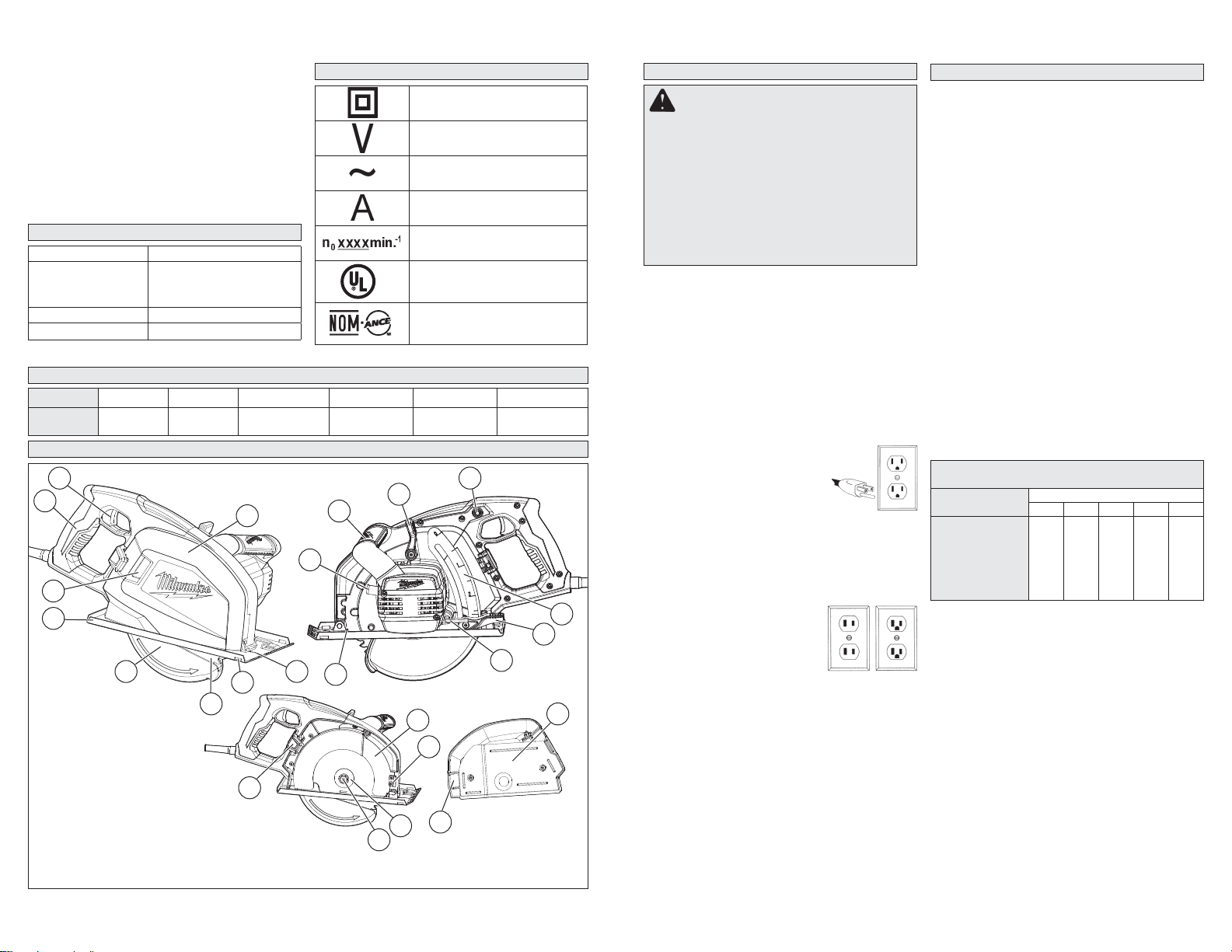
FUNCTIONAL DESCRIPTION
2
1
9
8
1. Handle
2. Trigger
7
3. Chip container
4. Sight line
5. Rip fence slot
6. Blade
7. Lower guard
8. Shoe
9. Chip viewing window
10. Spindle lock button
11. Front handle
12. Lower guard lever
13. Overload protector
14. Depth setting gauge
15. Depth adjusting lever
3
5
6
18
16. Hex wrench
17. Contact window
18. Latch
19. Upper guard
12
11
10
4
17
19
22
23
4
13
20
21
20. T ab
21. T ab pin
22. Outer blade fl ange
23. Blade bolt
15
16
14
3
GROUNDING
WARNING Improperly connecting the
grounding wire can result in the risk of electric shock. Check with a qualifi ed electrician
if you are in doubt as to whether the outlet is
properly grounded. Do not modify the plug
provided with the tool. Never remove the
grounding prong from the plug. Do not use
the tool if the cord or plug is damaged. If
damaged, have it repaired by a MILWAUKEE
service facility before use. If the plug will not
fi t the outlet, have a proper outlet installed by
a qualifi ed electrician.
Grounded Tools: Tools with Three Prong Plugs
Tools marked “Grounding Required” have a three
wire cord and three prong grounding plug. The
plug must be connected to a properly grounded
outlet (See Figure A). If the tool should electrically
malfunction or break down, grounding provides a
low resistance path to carry electricity away from
the user, reducing the risk of electric shock.
The grounding prong in the plug is connected
through the green wire inside the cord to the
grounding system in the tool. The green wire in the
cord must be the only wire connected to the tool's
grounding system and must never be attached to
an electrically “live” terminal.
Your tool must be plugged into
an appropriate outlet, properly
installed and grounded in accordance with all codes and ordinances.
The plug and outlet should look like
those in Figure A.
Double Insulated Tools:
Tools with Two Prong Plugs
Tools marked “Double Insulated” do not require
grounding. They have a special double insulation system which satisfi es OSHA requirements
and complies with the applicable standards of
Underwriters Laboratories, Inc.,
the Canadian Standard Association and the National Electrical Code. Double Insulated
tools may be used in either of
the 120 volt outlets shown in
Figures B and C.
Fig. A
Fig. B
Fig. C
EXTENSION CORDS
Grounded tools require a three wire extension
cord. Double insulated tools can use either a two
or three wire extension cord. As the distance from
the supply outlet increases, you must use a heavier
gauge extension cord. Using extension cords with
inadequately sized wire causes a serious drop in
voltage, resulting in loss of power and possible tool
damage. Refer to the table shown to determine the
required minimum wire size.
The smaller the gauge number of the wire, the
greater the capacity of the cord. For example, a 14
gauge cord can carry a higher current than a 16
gauge cord. When using more than one extension
cord to make up the total length, be sure each cord
contains at least the minimum wire size required.
If you are using one extension cord for more than
one tool, add the nameplate amperes and use the
sum to determine the required minimum wire size.
Guidelines for Using Extension Cords
• If you are using an extension cord outdoors, be
sure it is marked with the suffi x “W-A” (“W” in
Canada) to indicate that it is acceptable for outdoor
use.
• Be sure your extension cord is properly wired
and in good electrical condition. Always replace a
damaged extension cord or have it repaired by a
qualifi ed person before using it.
• Protect your extension cords from sharp objects,
excessive heat and damp or wet areas.
Recommended Minimum Wire Gauge
For Extension Cords*
Extension Cord Length
Nameplate Amps
0 - 2.0
2.1 - 3.4
3.5 - 5.0
5.1 - 7.0
7.1 - 12.0
12.1 - 16.0
16.1 - 20.0
* Based on limiting the line voltage drop to fi ve volts at
150% of the rated amperes.
25' 50' 75' 100' 150'
18
18
18
18
18
18
16
14
12
18
18
16
14
12
10
18
16
14
12
10
18
16
14
12
10
--
--
--
READ AND SAVE ALL
INSTRUCTIONS FOR FUTURE USE.
5
16
14
12
12
--
--
--
ASSEMBLY
WARNING To reduce the risk of injury ,
always unplug tool before changing or removing accessories. Only use accessories
specifi cally recommended for this tool. Others
may be hazardous.
Selecting Blade
Select an 8" blade appropriate for your application. Refer to the “Accessories” section for a list of
blades for this tool.
Always use sharp blades. Dull blades tend to
overload the tool and increase the chance of
KICKBACK. Only use blades with a maximum safe
operating speed greater than the no load RPM
marked on the tool's nameplate. Read the blade
manufacturer's instructions before use. Do not use
any type of abrasive cut-off wheel or dry diamond
cutting blades. Use the correct blade type for your
application. Using the wrong blade may result in
reduced performance or damage to the blade. Do
not use blades that are cracked or have broken
teeth. Do not sharpen ferrous metal cutting blades;
see the blade manufacturer's recommendations
regarding sharpening.
Checking the Operation of the Lower Guard
Check the operation and condition of the lower
guard lever. If the guard and the lever are not operating properly, they must be serviced before use.
Lower guard may operate sluggishly due to damaged parts, gummy deposits, or a buildup of debris.
1. Unplug tool before checking the lower guard.
2. Place the tool on its side.
NOTE: This procedure will not show proper lower
guard operation if the tool is not on its side.
3. Grasp the lower guard by the sides and push it
all the way back into the blade housing.
4. Release the lower guard.
• If the guard immediately springs back into
place, it is working correctly and you may continue with use.
• If the guard does not immediate spring back
into place, clean the upper and lower guards
to remove all chips and debris. Then, check
the operation again by starting with step 1.
• If the guard still does not immediately spring
back into place, contact a MILWAUKEE service
facility for repairs.
Removing and Installing Chip Container
WARNING
• NEVER operate tool when guards and chip
container are not installed. Serious injury
may occur.
• To reduce the risk of injury, wear safety
goggles or glasses with side shields when
removing the chip container. Chips and
debris may fl y up into the face.
1. Unplug tool before removing or installing chip
container.
2. To remove the chip container, open the latch
and pull the chip container off of the tab.
3. To install the chip container , fi t the tab pin onto the
tab, position the chip container, and secure the latch.
Installing and Removing Blades
1. Unplug tool before installing or removing blades.
2. Remove the chip container (see "Removing and
Installing Chip Container").
3. Place the saw on a fl at surface with the blade
facing up. To remove the blade bolt from the
spindle, push in the spindle lock button and hold.
Using the wrench provided with the tool, turn the
blade bolt counterclockwise. Remove the blade
bolt and outer blade fl ange. Do not remove the
inner blade fl ange.
4. Remove the blade from the spindle. Always clean
the spindle, upper guard, lower guard, and blade
fl anges to remove any chips and debris.
5. To install a blade, place the
blade on the spindle with the
teeth pointing in the same
direction as the arrow on the
lower guard.
6. Place the blade fl ange on the spindle and hand
tighten the blade bolt.
7. While holding in the spindle lock button, use
the wrench to turn the blade bolt clockwise and
tighten securely.
8. Replace the chip container (see "Removing and
Installing Chip Container").
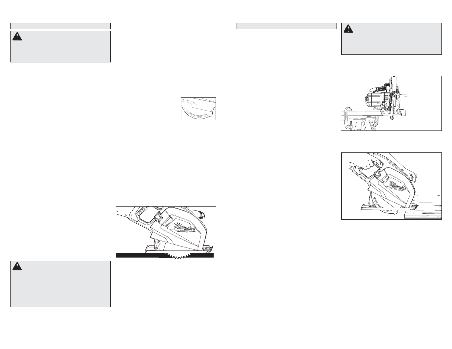
Adjusting Depth
1. Unplug tool before adjusting blade depth.
2. To adjust the depth of the cut, hold the saw by
the handle and loosen the depth adjusting lever
by pulling it up, away from the shoe.
3. Raise or lower the shoe to the desired position.
For the proper depth setting, the blade should
extend no more than 1/4” below the material
being cut.
4. Push the depth adjusting lever down to secure
the shoe position.
Fig.1
1/4"
Emptying the Chip Container
Chips and other debris from the workpiece are
collected inside the chip container, which needs to
be emptied to ensure proper functioning of the tool.
1. Unplug tool.
2. Remove the chip container (see "Removing and
Installing Chip Container") and empty. Use a
brush to ensure all chips and debris have been
removed.
3. Remove all chips and debris from upper guard,
blade, and housing.
4. Replace the chip container (see "Removing and
Installing Chip Container").
6
OPERATION
Kickback causes and related warnings
– Kickback is a sudden reaction to a pinched,
bound or misaligned saw blade, causing an uncontrolled saw to lift up and out of the workpiece
toward the operator;
– When the blade is pinched or bound tightly by the
kerf closing down, the blade stalls and the motor
reaction drives the unit rapidly back toward the
operator;
– If the blade becomes twisted or misaligned in
the cut, the teeth at the back edge of the blade
can dig into the top surface of the wood causing
the blade to climb out of the kerf and jump back
toward the operator.
Kickback is the result of saw misuse and/or incorrect operating procedures or conditions and can
be avoided by taking proper precautions as given
below:
• Maintain a fi rm grip with both hands on the
saw and position your arms to resist kickback
forces. Position your body to either side of the
blade, but not in line with the blade. Kickback
could cause the saw to jump backwards, but kickback forces can be controlled by the operator, if
proper precautions are taken.
• When blade is binding, or when interrupting
a cut for any reason, release the trigger and
hold the saw motionless in the material until
the blade comes to a complete stop. Never attempt to remove the saw from the work or pull
the saw backward while the blade is in motion
or kickback may occur. Investigate and take
corrective actions to eliminate the cause of blade
binding.
• When restarting a saw in the workpiece, centre
the saw blade in the kerf and check that saw
teeth are not engaged into the material. If saw
blade is binding, it may walk up or kickback from
the workpiece as the saw is restarted.
• Support large panels to minimise the risk of
blade pinching and kickback. Large panels tend
to sag under their own weight. Supports must be
placed under the panel on both sides, near the line
of cut and near the edge of the panel.
• Do not use dull or damaged blades. Unsharp-
ened or improperly set blades produce narrow
kerf causing excessive friction, blade binding and
kickback.
• Blade depth and bevel adjusting locking levers
must be tight and secure before making cut. If
blade adjustment shifts while cutting, it may cause
binding and kickback.
• Use extra caution when sawing into existing
walls or other blind areas. The protruding blade
may cut objects that can cause kickback.
WARNING To reduce the risk of injury ,
everyone in the work area should wear safety
goggles or glasses with side shields. Unplug
the tool before changing accessories or making adjustments.
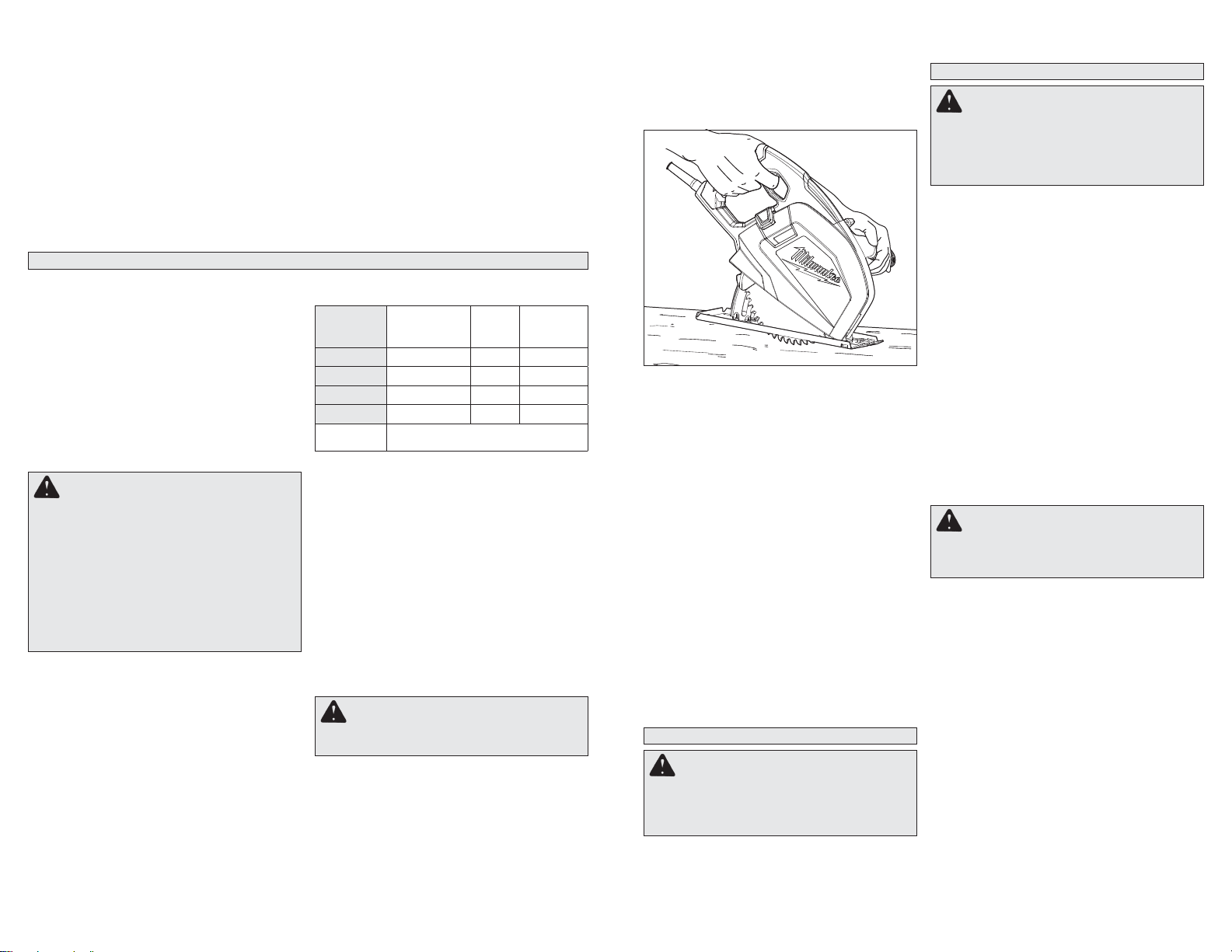
General Operation
Always clamp the workpiece securely on a saw
horse or bench. See “Applications” for the correct
way to support your work in different situations.
Fig.2
1. Draw a cutting line. Place the front of the shoe on
the edge of the workpiece without making blade
contact. Hold the trigger handle with one hand
and the front handle with the other.
Fig.3
2. Line up the sight line with your cutting line. Position your arms and body to resist KICKBACK.
3. Pull the trigger and allow the motor to reach full
speed before beginning cut.
4. While cutting, keep the shoe fl at against the
workpiece and maintain a fi rm grip. Do not force
the saw through the workpiece. Forcing a saw
can cause KICKBACK. Use a light, continuous
pressure to make the cut while following the cut
line through the sight line.
5. If making a partial cut, restarting in mid-cut or
correcting direction, allow the blade to come to
a complete stop. To resume cutting, center the
blade in the kerf, back the saw away from cutting
edge a few inches, pull the trigger and re-enter
the cut slowly.
6. If the saw binds and stalls, maintain a fi rm grip
and release the trigger immediately. Hold the
saw motionless in the workpiece until the blade
comes to a complete stop.
7. After fi nishing a cut, be sure the lower guard
closes and the blade comes to a complete stop
before setting the saw down.
7
Overload Protector
The overload protector automatically turns off
the tool when the motor is overloaded. The tool
can become overloaded when using a dull blade,
cutting material that is too thick, cutting materials
too quickly, or cutting hard metals such as stainless steel. To prevent the overload protector from
activating, always use a sharp blade and follow
the cutting instructions under the "Applications"
section. Do not attempt to defeat or override the
overload protector.
If the tool turns off automatically:
1. Release the trigger and unplug the tool.
2. Remove the blade from the workpiece.
APPLICATIONS
This tool is intended for cutting unhardened ferrous metal and non-ferrous metal. Refer to the
“Accessories” section for a list of blades to be
used for the proper applications of this tool. The
following precautions must be followed to reduce
the risk of injury:
• Do not cut stacked materials. Cut one piece at a time.
• Do not cut hardened steel.
• Cut materials with the wider edge of the shoe over
the clamped side of the material.
• Do not touch the blade, workpiece, chips, or chip
container with bare hands immediately after cutting; they may be hot and could burn skin.
Cutting Materials Thicker than 1/4"
(3/4" Maximum Thickness)
CAUTION! To reduce the risk of dam-
age to the tool or blade, do not exceed the
Feed Rate and Maximum Cut Time for materials thicker than 1/4", as charted below.
Between Maximum Cut Times, allow the tool
to cool down for 6 minutes of running with no
load or 60 minutes switched off.
Cutting too fast or too long in heavy material
will damage the tool if the tool is not allowed
to cool.
Cutting too slow will cause excessive wear
on the blade.
When cutting materials over 1/4", certain guidelines must be followed to avoid serious damage to
the tool and/or blade. The correct combination of
the following factors will allow for a sucessful cut
through thicker materials:
1. Material Thickness (do not cut materials thicker
than 3/4")
NOTE: If the material thickness is not shown
in the chart below, round up to the nearest
thickness listed in the chart and follow those
guidelines.
2. Maximum Length of Cut (the length of material
in inches through which the saw moves between
cool down periods)
3. Feed Rate (the speed at which the saw moves
through the material in seconds per inch)
4. Maximum Cutting Time (the total amount of
time that the saw can be under load between
cool down periods.
3. Allow the tool to rest for a miniumum of two
minutes.
4. Reset the overload protector by pushing in the
button.
Note: If the tool does not start after pushing the
button, allow the tool to cool for a few minutes
and try again.
5. Allow the tool to run under no load to ensure the
tool has properly cooled.
6. Resume the cut. When restarting a saw in the
workpiece, center the saw blade in the kerf, or
cut, and check that saw teeth are not engaged
into the material. If saw blade is binding, it may
walk up or KICKBACK from the workpiece as the
saw is restarted.
5. Cool Down Period (6 minutes running with no
load or 60 min. switched off.)
Material
Thickness
3/8" 30 - 45 15" 2 - 3
1/2" 18 - 36 9" 2 - 4
5/8" 18 - 30 6" 3 - 5
3/4" 20 - 25 5" 4 - 5
Cool Down
Period
Cutting Thin or Corrugated Materials
Cut thin and corrugated materials at least 1" from
the edge of the workpiece to avoid injury or damage to the tool caused by thin strips of metal being
pulled into the upper guard.
Cutting Large Sheets
Large sheets sag or bend if they are not correctly
supported. If you attempt to cut without leveling
and properly supporting the workpiece, the blade
will tend to bind, causing KICKBACK.
Support large sheets. Be sure to set the depth of
the cut so that you only cut through the workpiece,
not through the supports.
When cutting widths greater than 4", clamp 1"
lumber to workpiece and use the inside edge of
the shoe as a guide.
Pocket Cutting
Max
Cutting Time
(Seconds)
6 min. of running with no load
or 60 min. switched off
Max
Length
of Cut
Feed Rate
(sec./inch)
WARNING To reduce the risk of electric
shock, check work area for hidden pipes and
wires before making pocket cuts.
Pocket cuts are made in the middle of the workpiece
when it can not be cut from an edge. We recommend using a Sawzall
saw for this type of cut. However, if you must use a
circular saw to make a pocket cut, USE EXTREME
CAUTION. To maintain control of the saw during
pocket cutting, keep both hands on the saw.
8
®
reciprocating saw or jig
1.
Beginning at a corner, line up the sight line with
your cutting line. Tilt the saw forward, fi rmly fi xing
the front of the shoe on the workpiece. The blade
should be just above cutting line, but not touching it.
Raise the lower guard using the lower guard lever.
Fig.4
2. Pull the trigger and allow the motor to reach full
speed before beginning cut. Using the front of the
shoe as a hinge point, gradually lower the back
end of the saw into the workpiece. Release the
lower guard lever.
3. When the shoe rests fl at against workpiece,
advance the saw to the far corner. Release the
trigger and allow the blade to come to a complete
stop before removing it from workpiece. Repeat
the above steps for each side of the opening.
Use a Sawzall® reciprocating saw, jig saw or
small hand saw to fi nish the corners if they are
not completely cut through.
Troubleshooting
If the blade does not follow a straight line:
• Teeth are dull. This is caused by hitting a hard
object, dulling teeth on one side. The blade tends
to cut to the side with the sharpest teeth.
• Shoe is out of line or bent
• Blade is bent
If the blade binds, smokes or turns blue from friction:
• Blade is dull
• Blade is on backwards
• Blade is bent
• Blade is dirty
• Workpiece is not properly supported
• Incorrect blade is being used
ACCESSORIES
WARNING To reduce the risk of injury,
always unplug the tool before attaching or
removing accessories. Use only specifi cally
recommended accessories. Others may be
hazardous.
For a complete listing of accessories refer to your
MILWAUKEE Electric Tool catalog or go on-line
to www.milwaukeetool.com. To obtain a catalog,
contact your local distributor or a service center.
MAINTENANCE
WARNING T o reduce the risk of injury,
always unplug your tool before performing
any maintenance. Never disassemble the tool
or try to do any rewiring on the tool’s electrical
system. Contact a MILWAUKEE service facility
for ALL repairs.
Maintaining Tools
Keep your tool in good repair by adopting a regular
maintenance program. Before use, examine the
general condition of your tool. Inspect guards,
switches, tool cord set and extension cord for
damage. Check for loose screws, misalignment,
binding of moving parts, improper mounting, broken parts and any other condition that may affect
its safe operation. If abnormal noise or vibration
occurs, turn the tool off immediately and have the
problem corrected before further use. Do not use a
damaged tool. Tag damaged tools “DO NOT USE”
until repaired (see “Repairs”).
Under normal conditions, relubrication is not necessary until the motor brushes need to be replaced.
After six months to one year, depending on use,
return your tool to the nearest MILWAUKEE service
facility for the following:
• Lubrication
• Brush inspection and replacement
• Mechanical inspection and cleaning (gears, spindles, bearings, housing, etc.)
• Electrical inspection (switch, cord, armature, etc.)
• Testing to assure proper mechanical and electrical
operation
WARNING T o reduce the risk of injury,
electric shock and damage to the tool, never
immerse your tool in liquid or allow a liquid
to fl ow inside the tool.
Cleaning
Clean dust and debris from vents. Keep the tool
handles clean, dry and free of oil or grease. Use
only mild soap and a damp cloth to clean your
tool since certain cleaning agents and solvents
are harmful to plastics and other insulated parts.
Some of these include: gasoline, turpentine, lacquer
thinner, paint thinner , chlorinated cleaning solvents,
ammonia and household detergents containing
ammonia. Never use fl ammable or combustible
solvents around tools.
Repairs
If your tool is damaged, return the entire tool to the
nearest service center.
9
 Loading...