

Milwaukee Tool 6276-20 User Manual [en, es, fr]
OPERATOR'S MANUAL
MANUEL de L'UTILISATEUR
MANUAL del OPERADOR
Cat. No.
No de cat.
6276-20
JIG SAW
SCIE SAUTEUSE
SIERRA CALADORA
TO REDUCE THE RISK OF INJURY, USER MUST READ AND UNDERSTAND OPERATOR'S
MANUAL.
AFIN DE RÉDUIRE LE RISQUE DE BLESSURES, L'UTILISATEUR DOIT LIRE ET BIEN
COMPRENDRE LE MANUEL DE L'UTILISATEUR.
PARA REDUCIR EL RIESGO DE LESIONES, EL USUARIO DEBE LEER Y ENTENDER EL
MANUAL DEL OPERADOR.

GENERAL POWER TOOL SAFETY WARNINGS
WARNING READ ALL SAFETY WARNINGS AND ALL INSTRUCTIONS.
Failure to follow the warnings and instructions may result in electric shock, fi re and/or
serious injury. Save all warnings and instructions for future reference.
The term "power tool" in the warnings refers to your mains-operated (corded) power tool or
battery-operated (cordless) power tool.
• Keep work area clean and well lit. Cluttered or
dark areas invite accidents.
• Do not operate power tools in explosive atmospheres, such as in the presence of fl am-
mable liquids, gases or dust. Power tools create
sparks which may ignite the dust or fumes.
• Keep children and bystanders away while
operating a power tool. Distractions can cause
you to lose control.
ELECTRICAL SAFETY
WORK AREA SAFETY
• Power tool plugs must match the outlet. Never
modify the plug in any way. Do not use any
adapter plugs with earthed (grounded) power
tools. Unmodifi ed plugs and matching outlets will
reduce risk of electric shock.
• Avoid body contact with earthed or grounded
surfaces such as pipes, radiators, ranges and
refrigerators. There is an increased risk of electric
shock if your body is earthed or grounded.
• Do not expose power tools to rain or wet conditions. Water entering a power tool will increase
the risk of electric shock.
• Do not abuse the cord. Never use the cord for
carrying, pulling or unplugging the power tool.
Keep cord away from heat, oil, sharp edges
or moving parts. Damaged or entangled cords
increase the risk of electric shock.
• When operating a power tool outdoors, use an
extension cord suitable for outdoor use. Use
of a cord suitable for outdoor use reduces the risk
of electric shock.
• If operating a power tool in a damp location
is unavoidable, use a residual current device
(RCD) protected supply. Use of an RCD reduces
the risk of electric shock.
PERSONAL SAFETY
• Stay alert, watch what you are doing and use
common sense when operating a power tool. Do
not use a power tool while you are tired or under
the infl uence of drugs, alcohol or medication. A
moment of inattention while operating power tools
may result in serious personal injury.
• Use personal protective equipment. Always
wear eye protection. Protective equipment such
as dust mask, non-skid safety shoes, hard hat, or
hearing protection used for appropriate conditions
will reduce personal injuries.
• Prevent unintentional starting. Ensure the
switch is in the off-position before connecting
to power source and/or battery pack, picking
up or carrying the tool. Carrying power tools with
your fi nger on the switch or energising power tools
that have the switch on invites accidents.
• Remove any adjusting key or wrench before
2
turning the power tool on. A wrench or a key left
attached to a rotating part of the power tool may
result in personal injury.
• Do not overreach. Keep proper footing and
balance at all times. This enables better control
of the power tool in unexpected situations.
• Dress properly. Do not wear loose clothing or
jewellery. Keep your hair, clothing and gloves
away from moving parts. Loose clothes, jewel-
lery or long hair can be caught in moving parts.
• If devices are provided for the connection of
dust extraction and collection facilities, ensure
these are connected and properly used. Use of
dust collection can reduce dust-related hazards.
POWER TOOL USE AND CARE
• Do not force the power tool. Use the correct
power tool for your application. The correct
power tool will do the job better and safer at the
rate for which it was designed.
• Do not use the power tool if the switch does not
turn it on and off. Any power tool that cannot be
controlled with the switch is dangerous and must
be repaired.
• Disconnect the plug from the power source
and/or the battery pack from the power tool
before making any adjustments, changing
accessories, or storing power tools. Such
preventive safety measures reduce the risk of
starting the power tool accidentally.
• Store idle power tools out of the reach of children and do not allow persons unfamiliar with
the power tool or these instructions to operate
the power tool. Power tools are dangerous in the
hands of untrained users.
• Maintain power tools. Check for misalignment
or binding of moving parts, breakage of parts
and any other condition that may affect the
power tool’s operation. If damaged, have the
power tool repaired before use. Many accidents
are caused by poorly maintained power tools.
• Keep cutting tools sharp and clean. Properly
maintained cutting tools with sharp cutting edges
are less likely to bind and are easier to control.
• Use the power tool, accessories and tool bits
etc., in accordance with these instructions,
taking into account the working conditions and
the work to be performed. Use of the power tool
for operations different from those intended could
result in a hazardous situation.
SERVICE
• Have your power tool serviced by a qualifi ed
repair person using only identical replacement
parts. This will ensure that the safety of the power
tool is maintained.
3
SERVICE
• Have your power tool serviced by a qualifi ed
repair person using only identical replacement
parts. This will ensure that the safety of the power
tool is maintained.
SPECIFIC SAFETY RULES
• Hold power tool by insulated gripping surfaces,
when performing an operation where the cutting
accessory may contact hidden wiring or its own
cord. Cutting accessory contacting a live wire may
make exposed metal parts of the power tool live and
could give the operator an electric shock.
• Use clamps or another practical way to secure
and support the workpiece to a stable platform.
Holding the work by hand or against your body
leaves it unstable and may lead to loss of control.
• Keep hands away from all cutting edges and
moving parts.
• Maintain labels and nameplates. These carry
important information. If unreadable or missing,
contact a MILWAUKEE service facility for a free
replacement.
• WARNING Some dust created by power sanding,
sawing, grinding, drilling, and other construction
activities contains chemicals known to cause
cancer, birth defects or other reproductive harm.
Some examples of these chemicals are:
• lead from lead-based paint
• crystalline silica from bricks and cement and other
masonry products, and
•arsenic and chromium from chemically-treated
lumber.
Y our risk from these exposures varies, depending
on how often you do this type of work. To reduce
your exposure to these chemicals: work in a well
ventilated area, and work with approved safety
equipment, such as those dust masks that are specially designed to fi lter out microscopic particles.
SPECIFICATIONS
Cat.
Volts
No.
6276-21 120 6.2 500-3000 1"
AC
Amps
No Load
Strokes Per
Minute
Length of
Stroke
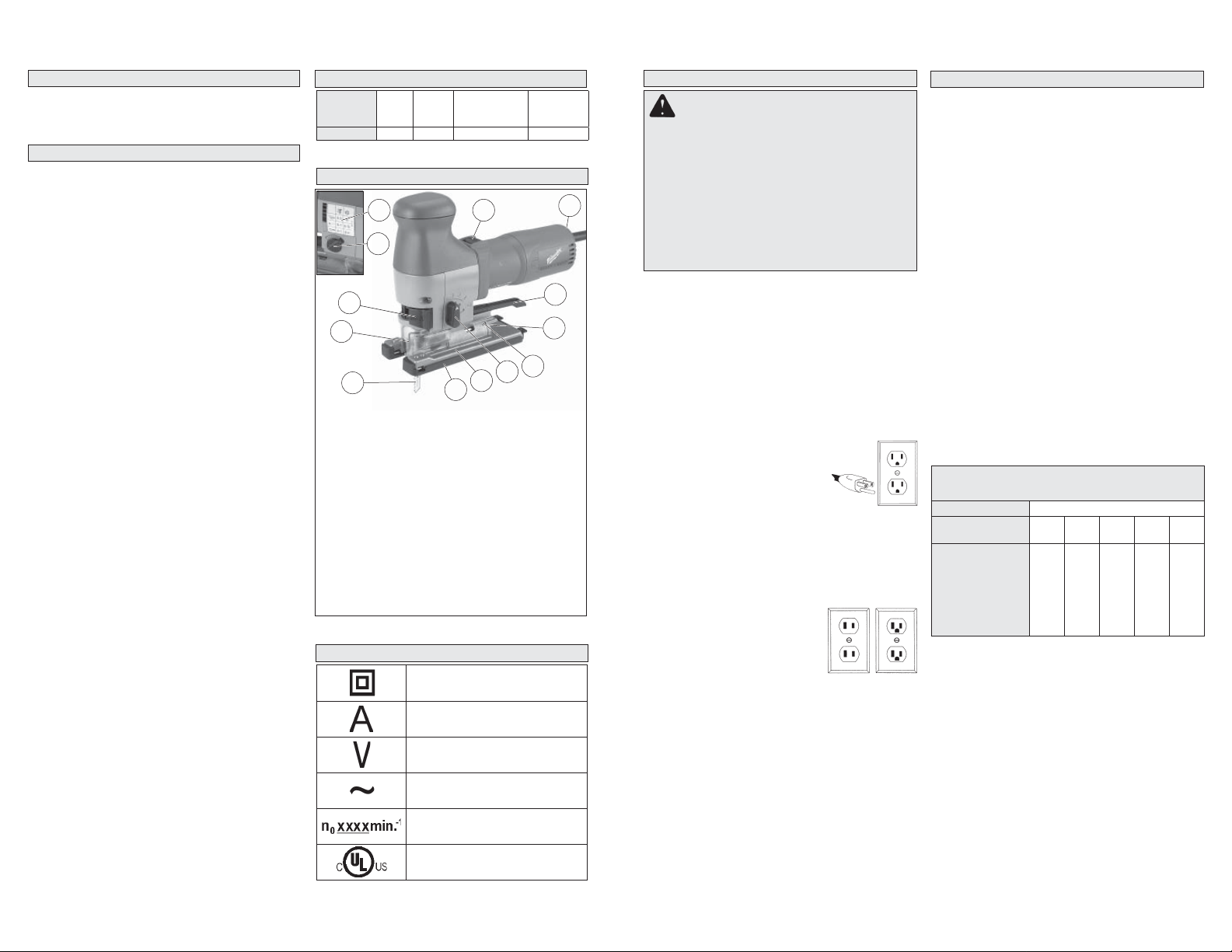
FUNCTIONAL DESCRIPTION
13
12
1
2
3
1. Quik-Lok tension lever
2. Transparent blade cover
3. Blade
4. Shoe cover
5. Keyless shoe
6. Orbital action selector lever
7. Tilt angle scale
8. Vacuum manifold
9. Shoe adjustment lever
10. On/Off switch
11. Speed control dial
12. Blower adjustment dial
13. Cutting guide
10
7
6
5
4
SYMBOLOGY
Double Insulated
GROUNDING
EXTENSION CORDS
Grounded tools require a three wire extension
WARNING Improperly connecting the
grounding wire can result in the risk of electric shock. Check with a qualifi ed electrician
if you are in doubt as to whether the outlet is
properly grounded. Do not modify the plug
provided with the tool. Never remove the
grounding prong from the plug. Do not use
11
9
8
the tool if the cord or plug is damaged. If
damaged, have it repaired by a MILWAUKEE
service facility before use. If the plug will not
fi t the outlet, have a proper outlet installed by
a qualifi ed electrician.
Grounded Tools: Tools with Three Prong Plugs
Tools marked “Grounding Required” have a three
wire cord and three prong grounding plug. The
plug must be connected to a properly grounded
outlet (See Figure A). If the tool should electrically
malfunction or break down, grounding provides a
low resistance path to carry electricity away from
the user, reducing the risk of electric shock.
The grounding prong in the plug is connected
through the green wire inside the cord to the
grounding system in the tool. The green wire in the
cord must be the only wire connected to the tool's
grounding system and must never be attached to
an electrically “live” terminal.
Your tool must be plugged into
an appropriate outlet, properly
installed and grounded in accordance with all codes and ordinances.
The plug and outlet should look like
those in Figure A.
Fig. A
Double Insulated Tools:
Tools with Two Prong Plugs
Tools marked “Double Insulated” do not require
grounding. They have a special double insulation system which satisfi es OSHA requirements
and complies with the applicable standards of
Underwriters Laboratories, Inc.,
the Canadian Standard Association and the National Electrical Code. Double Insulated
tools may be used in either of
the 120 volt outlets shown in
Figures B and C.
Fig. B
Fig. C
cord. Double insulated tools can use either a two
or three wire extension cord. As the distance from
the supply outlet increases, you must use a heavier
gauge extension cord. Using extension cords with
inadequately sized wire causes a serious drop in
voltage, resulting in loss of power and possible tool
damage. Refer to the table shown to determine the
required minimum wire size.
The smaller the gauge number of the wire, the
greater the capacity of the cord. For example, a 14
gauge cord can carry a higher current than a 16
gauge cord. When using more than one extension
cord to make up the total length, be sure each cord
contains at least the minimum wire size required.
If you are using one extension cord for more than
one tool, add the nameplate amperes and use the
sum to determine the required minimum wire size.
Guidelines for Using Extension Cords
• If you are using an extension cord outdoors, be
sure it is marked with the suffi x “W-A” (“W” in
Canada) to indicate that it is acceptable for outdoor
use.
• Be sure your extension cord is properly wired
and in good electrical condition. Always replace a
damaged extension cord or have it repaired by a
qualifi ed person before using it.
• Protect your extension cords from sharp objects,
excessive heat and damp or wet areas.
Recommended Minimum Wire Gauge
For Extension Cords*
Nameplate
Amperes
0 - 2.0
2.1 - 3.4
3.5 - 5.0
5.1 - 7.0
7.1 - 12.0
12.1 - 16.0
16.1 - 20.0
* Based on limiting the line voltage drop to fi ve volts at
150% of the rated amperes.
Extension Cord Length
25' 50' 75' 100' 150'
18
18
18
18
18
18
18
16
14
12
18
18
16
14
12
10
18
16
14
12
10
--
16
14
12
10
16
14
12
12
--
--
--
--
--
READ AND SAVE ALL
INSTRUCTIONS FOR FUTURE USE.
Amperes
Volts
Alternating Current
No Load Revolutions
per Minute (RPM)
Underwriters Laboratories, Inc.
United States and Canada
4
5

ASSEMBLY
WARNING T o reduce the risk of injury ,
always unplug tool before attaching or removing accessories or making adjustments. Use
only specifi cally recommended accessories.
Others may be hazardous.
Installing Saw Blades
Use only T-Shank jig saw
blades.
1. Unplug tool.
2. Pull out and hold the QuikLok tension lever.
3. Fit the saw blade into the
groove in the support roller
and push it fi rmly into the
plunger as far as it will go;
the lug of the saw blade
must be in the plunger.
4. Release the Quik-Lok tension lever to secure the
saw blade.
5. Check that the saw blade
is held fi rmly; the slot in
the plunger will be at an angle
to the blade.
Fig. 1
Plunger
Support
roller
Lug
Slot
Blade
Adjusting the shoe
The shoe may be tilted up to 45° in either direction
and moved forward or backward.
To set a tilt angle for angle cuts and bevels,
loosen the shoe adjustment lever and pull the base
forward slightly until the retaining lugs are no longer
engaged. Tilt the shoe to the required preset angle
(15°, 30°, or 45°) as read on the tilt angle scale.
Push back the shoe into the retaining lugs and
tighten the shoe adjustment lever. If angles other
than the presets are required, set the desired angle
and tighten the shoe adjustment lever without
engaging the retaining lugs.
If very exact angles are needed it is recommended
that a test cut and subsequent adjustment be made.
Fig. 3
Using the shoe cover
The shoe cover is used to prevent marring and scratching
of the workpiece surface. To
Fig. 4
Anti-splinter
device
attach the shoe cover, hook
the front of the cover over the
steel shoe. Next, snap the
rear of the shoe cover to the
steel shoe. Be sure both sides
Shoe
cover
are snapped in place.
When the shoe cover is not
needed, remove it by pulling
the tabs on rear of the shoe cover outward from
the steel shoe. Unhook the front of the shoe cover
and remove.
Using the anti-splinter device
The anti-splinter device helps stablize the workpiece and reduces workpiece splinter.
T o use, slide the anti-splinter device onto the shoe
or shoe cover. Make sure the anti-splinter device
is installed fl ush with the bottom of the shoe and
shoe cover, as applicable.
OPERATION
WARNING T o reduce the risk of injury ,
always unplug tool before attaching or removing accessories or making adjustments. Use
only specifi cally recommended accessories.
Others may be hazardous.
WARNING T o reduce the risk of injury ,
wear safety goggles or glasses with side
shields.
Orbital Action jig saws can cut a wide variety of
materials including metal, wood and plastic. Cuts
may be straight lines, bevels, curves or internal
cut-outs. Notable features of these jig saws include:
• Rapid blade change without tools with the QuikLok blade change system.
• Adjustable Orbital Action blade stroke cuts faster
by pressing the blade against the work only
during the upstroke. This is particularly effective
when rough cutting thick wooden boards.
• Electronic dial speed control maintains the preset speed during the cut.
• Adjustable shoe can be tilted by up to 45 degrees
in either direction for bevel cuts.
• Non-marring shoe cover to protect the surface
of workpiece from marring and scratching.
• Sawdust blower removes the sawdust ahead of
the cut for improved visibility.
• Built-in manifold for vacuum assisted dust collection (hose is optional).
• Transparent blade cover improves dust extraction.
• Vibration dampened mechanism permits quieter,
smoother running.
WARNING T o reduce the risk of injury ,
do not start the tool with the blade contacting
the workpiece.
Starting and stopping the tool
1. To start the tool, push the On/Off switch forward
until “I” is visible.
2. To stop the tool, push the On/Off switch back-
wards until “0” is visible.
Adjusting stroke per minute
The strokes per minute may be adjusted with the
speed control dial. The numbers 1 through 7 are
printed on the dial with 1 being the slowest speed
and 7 the highest speed. Recommended cutting
speeds for various materials are listed below.
Optimum cutting speeds should be determined by
the user for specifi c cutting requirements. Strokes
per minute may be adjusted when the tool is running or stopped.
Material Recommended cutting speed
Wood 7
Metal 4-5
Plastic 2
Adjusting the orbital action
The amount of orbital action may be adjusted with
the orbital action selector lever. In general, a large
orbital action (3) should be used with soft materials and a no orbital action (0) should be used with
hard materials. When a smooth cut is required
no orbit (0) should be used. Recommended orbit
settings for different material
compositions are listed below.
The optimum orbital action
should be determined by the
user for their specifi c cutting
requirements. Orbital action
may be adjusted when the tool
Material
Wood 3
Metal 0
Plastic 1
Smooth Cut 0
Orbital
Action
is running or stopped.
Making the Cut
1. Set the stroke and orbital action according the
material to be cut.
2. Position the tool with the front part of the shoe
on the workpiece and start the tool.
3. Hold the machine firmly against the workpiece and guide it along the desired cutting
line. Do not feed into the work too hard, light
pressure on the saw blade will achieve the optimum cutting speed.
Special Cutting Techniques
1. Straight cuts — To obtain a perfectly straight
cut, clamp a strip of wood as a guide along the
workpiece or use the rip guide (accessory).
2. Bevel cuts — adjust the shoe to the correct angle
(see Adjusting the Shoe).
3. Cutting Sheet Metal — sheet metal may vibrate
when being cut. T o minimize vibration clamp, the
workpiece to a wood base.
6
7
 Loading...