

Milwaukee 6256, 6101, 4262-1, 4253-1, 4292-1 Operator's Manual
...
OPERATOR'S MANUAL
MANUEL de L'UTILISATEUR
MANUAL del OPERADOR
Catalog No.
No de Cat.
Catálogo No.
6256
HEAVY-DUTY JIG SAWS
EXTRA ROBUSTES SCIES SAUTEUSES
SIERRAS CALADORAS HEAVY-DUTY
TO REDUCE THE RISK OF INJURY, USER MUST READ AND UNDERSTAND OPERATOR'S MANUAL.
AFIN DE RÉDUIRE LE RISQUE DE BLESSURES, L'UTILISATEUR DOIT LIRE ET BIEN COMPRENDRE LE
MANUEL DE L'UTILISATEUR.
PARA REDUCIR EL RIESGO DE LESIONES, EL USUARIO DEBE LEER Y ENTENDER EL MANUAL DEL
OPERADOR.

GENERAL SAFETY RULES FOR ALL POWER TOOLS
WARNING!
Failure to follow all instructions listed below may result in electric shock, fire and/or serious injury. The term "power tool" in
all of the warnings listed below refers to your mains-operated (corded) power tool or battery-opearted (cordless) power tool.
SAVE THESE INSTRUCTIONS
READ ALL INSTRUCTIONS
WORK AREA SAFETY
1. Keep work area clean and well lit. Cluttered or dark areas invite
accidents.
2. Do not operate power tools in explosive atmospheres, such
as in the presence of flammable liquids, gases, or dust.
Power tools create sparks which may ignite the dust or fumes.
3. Keep children and bystanders away while operating a power
tool. Distractions can cause you to lose control.
ELECTRICAL SAFETY
4. Power tool plugs must match the outlet. Never modify the
plug in any way. Do not use any adapter plugs with earthed
(grounded) power tools. Unmodified plugs and matching outlets
will reduce risk of electric shock.
5. Avoid body contact with earthed or grounded surfaces such
as pipes, radiators, ranges and refrigerators. There is an
increased risk of electric shock if your body is earthed or grounded.
6. Do not expose power tools to rain or wet conditions. Water
entering a power tool will increase the risk of electric shock.
7. Do not abuse the cord. Never use the cord for carrying,
pulling, or unplugging the power tool. Keep cord away from
heat, oil, sharp edges, or moving parts. Damaged or entangled
cords increase the risk of electric shock.
8. When operating a power tool outdoors, use an extension
cord suitable for outdoor use. Use of a cord suitable for outdoor
use reduces the risk of electric shock.
PERSONAL SAFETY
16. Do not force the power tool. Use the correct power tool for
your application. The correct power tool will do the job better and
safer at the rate for which it was designed.
17. Do not use the power tool if the switch does not turn it on
and off. Any power tool that cannot be controlled with the switch is
dangerous and must be repaired.
18. Disconnect the plug from the power source and/or the bat-
tery pack from the power tool before making any adjustments, changing accessories, or storing power tools. Such
preventive safety measures reduce the risk of starting the tool accidentally.
19. Store idle power tools out of the reach of children and do
not allow persons unfamiliar with the power tools or these
instructions to operate power tools. Power tools are danger-
ous in the hands of untrained users.
20. Maintain power tools. Check for misalignment or binding of
moving parts, breakage of parts and any other condition
that may affect the power tool's operation. If damaged, have
the power tool repaired before use. Many accidents are caused
by poorly maintained power tools.
21. Keep cutting tools sharp and clean. Properly maintained cutting
tools with sharp cutting edges are less likely to bind and are easier
to control.
22. Use the power tool, accessories and tool bits etc., in accor-
dance with these instructions and in the manner intended
for the particular type of power tool, taking into account the
working conditions and the work to be performed. Use of
the power tool for operations different from those intended could
result in a hazardous situation.
POWER TOOL USE AND CARE
SERVICE
9. Stay alert, watch what you are doing and use common sense
when operating a power tool. Do not use a power tool while
you are tired or under the influence of drugs, alcohol or
medication. A moment of inattention while operating power tools
may result in serious personal injury.
10. Use safety equipment. Always wear eye protection. Safety
equipment such as dust mask, non-skid safety shoes, hard hat, or
hearing protection used for appropriate conditions will reduce personal injuries.
11. Avoid accidental starting. Ensure the switch is in the off-
position before plugging in. Carrying tools with your finger on
the switch or plugging in power tools that have the switch on invites
accidents.
12. Remove any adjusting key or wrench before turning the
power tool on. A wrench or a key left attached to a rotating part of
the power tool may result in personal injury.
13. Do not overreach. Keep proper footing and balance at all
times. This enables better control of the power tool in unexpected
situations.
14. Dress properly. Do not wear loose clothing or jewellery.
Keep your hair, clothing and gloves away from moving parts.
Loose clothes, jewellery, or long hair can be caught in moving parts.
15. If devices are provided for the connection of dust extrac-
tion and collection facilities, ensure these are connected
and properly used. Use of these devices can reduce dust-re-
lated hazards.
page 2
23. Have your power tool serviced by a qualified repair person
using only identical replacement parts. This will ensure that
the safety of the power tool is maintained.
SPECIFIC SAFETY RULES
1. Hold power tools by insulated gripping surfaces when performing an operation where the cutting tool may contact hidden
wiring or its own cord. Contact with a live wire will make exposed metal parts of the tool live and shock the operator.
2. Keep hands away from all cutting edges and moving parts.
3. Use clamps or another practical way to secure and support the workpiece to a stable platform. Holding the work by hand or against
your body leaves it unstable and may lead to loss of control.
4. Maintain labels and nameplates. These carry important information. If unreadable or missing, contact a MILWAUKEE service facility for a free
replacement.
5. WARNING! Some dust created by power sanding, sawing, grinding, drilling, and other construction activities contains chemicals known to cause
cancer, birth defects or other reproductive harm. Some examples of these chemicals are:
lead from lead-based paint
crystalline silica from bricks and cement and other masonry products, and
arsenic and chromium from chemically-treated lumber.
Your risk from these exposures varies, depending on how often you do this type of work. To reduce your exposure to these chemicals: work in
a well ventilated area, and work with approved safety equipment, such as those dust masks that are specifically designed to filter out
microscopic particles.
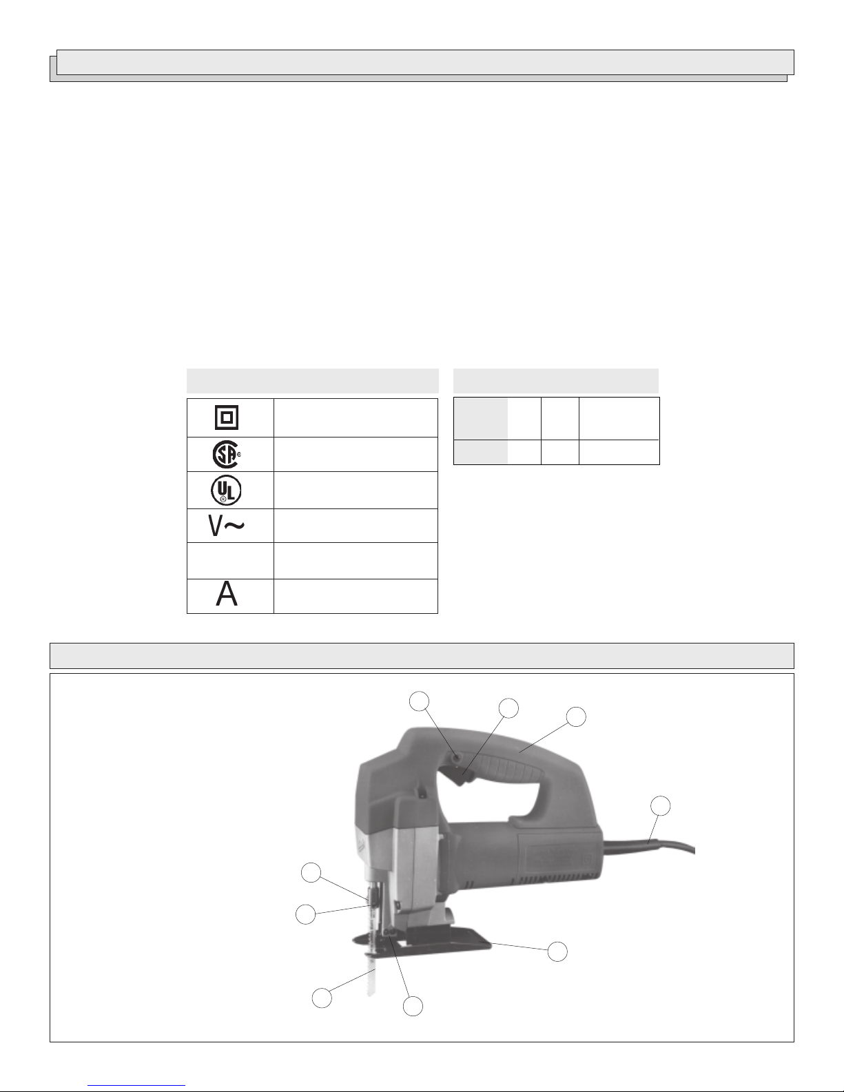
1. Lock button
2. Trigger
3. Top handle
4. Cord
5. Shoe
6. Blade roller
7. Blade
8. Spindle
9. Blade clamp screw
S.P.M.
Symbology
Double Insulated
Canadian Standards
Association
Underwriters
Laboratories, Inc.
Volts Alternating Current
Strokes per Minute (S.P.M.)
Amperes
FUNCTIONAL DESCRIPTION
Specifications
Catalog
Number
6256
1
Volts
AC
120
2
Amps
3.8
3
Strokes Per
Minute
0 - 3 100
4
9
8
5
7
6
page 3

GROUNDING EXTENSION CORDS
WARNING!
Improperly connecting the grounding wire can result in the
risk of electric shock. Check with a qualified electrician if you
are in doubt as to whether the outlet is properly grounded.
Do not modify the plug provided with the tool. Never remove
the grounding prong from the plug. Do not use the tool if the
cord or plug is damaged. If damaged, have it repaired by a
MILWAUKEE service facility before use. If the plug will not fit
the outlet, have a proper outlet installed by a qualified
electrician.
Grounded Tools:
Tools with Three Prong Plugs
Tools marked Grounding Required
have a three wire cord and three
prong grounding plug. The plug must
be connected to a properly grounded
outlet (See Figure A). If the tool should
electrically malfunction or break
down, grounding provides a low resistance path to carry electricity
away from the user, reducing the risk
of electric shock.
The grounding prong in the plug is connected through the green wire
inside the cord to the grounding system in the tool. The green wire in the
cord must be the only wire connected to the tool's grounding system and
must never be attached to an electrically live terminal.
Your tool must be plugged into an appropriate outlet, properly installed
and grounded in accordance with all codes and ordinances. The plug
and outlet should look like those in Figure A.
Double Insulated Tools:
Tools with Two Prong Plugs
Tools marked Double Insulated do
not require grounding. They have a
special double insulation system
which satisfies OSHA requirements
and complies with the applicable
standards of Underwriters Laboratories, Inc., the Canadian Standard
Association and the National Electrical Code. Double Insulated tools may
be used in either of the 120 volt outlets shown in Figures B and C.
Fig. A
Fig. B
Fig. C
Grounded tools require a three wire extension cord. Double insulated
tools can use either a two or three wire extension cord. As the distance
from the supply outlet increases, you must use a heavier gauge extension cord. Using extension cords with inadequately sized wire causes a
serious drop in voltage, resulting in loss of power and possible tool
damage. Refer to the table shown to determine the required minimum
wire size.
The smaller the gauge number of the wire, the greater the capacity of the
cord. For example, a 14 gauge cord can carry a higher current than a 16
gauge cord. When using more than one extension cord to make up the
total length, be sure each cord contains at least the minimum wire size
required. If you are using one extension cord for more than one tool, add
the nameplate amperes and use the sum to determine the required minimum wire size.
Guidelines for Using Extension Cords
If you are using an extension cord outdoors, be sure it is marked
with the suffix W-A (W in Canada) to indicate that it is acceptable
for outdoor use.
Be sure your extension cord is properly wired and in good electrical
condition. Always replace a damaged extension cord or have it
repaired by a qualified person before using it.
Protect your extension cords from sharp objects, excessive heat
and damp or wet areas.
Recommended Minimum Wire Gauge
Nameplate
Amperes
8.1 - 12
12.1 - 15
15.1 - 20
* Based on limiting the line voltage drop to five
volts at 150% of the rated amperes.
for Extension Cords*
25'
0 - 5
5.1 - 8
16
16
14
12
10
Extension Cord Length
100'
14
12
10
10
150'
12
10
--
--
--
--
50'
16
16
14
12
10
75'
16
14
12
10
10
200'
12
--
--
--
--
READ AND SAVE ALL INSTRUCTIONS
FOR FUTURE USE.
page 4
TOOL ASSEMBLY
WARNING!
To reduce the risk of injury, always unplug tool before
attaching or removing accessories or making adjustments.
Use only specifically recommended accessories. Others
may be hazardous.
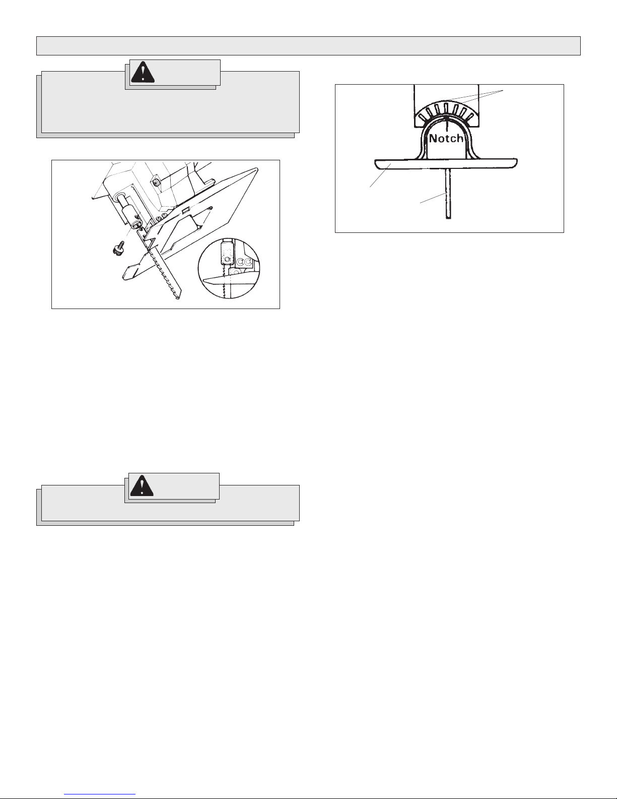
Inserting Blades (Fig. 1)
Fig. 1
1. Unplug tool. This tool uses only 1/4" universal tang blades. Select
appropriate blade for the job.
2. To insert blade, loosen blade clamp screw.
3. Insert blade into spindle.
4. Line up holes in spindle and blade.
5. Insert blade clamp screw through holes.
6. Hand tighten blade clamp screw.
7. When properly installed, back of blade will fit into groove on blade
roller.
8. Finish tightening blade clamp screw with a screwdriver.
9. To remove blade, loosen blade clamp screw and slide blade out of
spindle.
Adjusting Shoe (Fig. 2)
Fig. 2
Shoe
Blade
For angle cutting, shoe may be tilted up to 45° in either direction.
1. To adjust angle, unplug tool.
2. Loosen large shoe retaining screw under shoe with a large flat
blade screwdriver.
3. Slide shoe toward rear of tool as far as possible (about 1/2").
4. Shoe may now be adjusted to desired angle. Lower rear of gear
case is marked with lines at 15° intervals. Line up notch in shoe with
marking desired
5. Tighten shoe retaining screw securely.
6. To return tool to position for 90° cuts, loosen shoe retaining screw,
align notch with center line and slide shoe forward. Tighten shoe
retaining screw securely.
Using Rip Fence Kit
1. Unplug tool.
2. Insert rip fence through slots in shoe with edge guide facing up.
3. Place edge guide against edge of work.
4. Adjust fence to obtain desired straight cutting width
5. Tighten thumb screw to secure fence.
15°
WARNING!
Blade and clamping screw may be hot after use.
page 5
OPERATION
WARNING!
To reduce the risk of injury, wear safety goggles or glasses
with side shields. Unplug the tool before changing accessories or making adjustments.
Controlling Trigger Speed
Pressing the trigger will produce various speeds from 0 to 3 100 strokes
per minute. The further the trigger is pressed, the greater the speed.
Locking Trigger
The trigger lock button allows tool to run continuously at maximum preset
speed.
1. To engage the lock button, squeeze the trigger as far as possible,
and push in the lock button.
2. While holding in the lock button, release the trigger. The trigger will
lock in place.
3. To release the lock button, squeeze the trigger until the lock button
pops out.
Cutting from Edge
1. Hold saw firmly, allowing shoe to rest on workpiece without making
blade contact.
2. Line up blade with line of cut, squeeze trigger and advance saw.
3. For best results, maintain firm, downward pressure, keeping shoe
on workpiece. Use just enough forward pressure to advance blade
into work. Forcing cut will not increase cutting speed and may damage blade or tool.
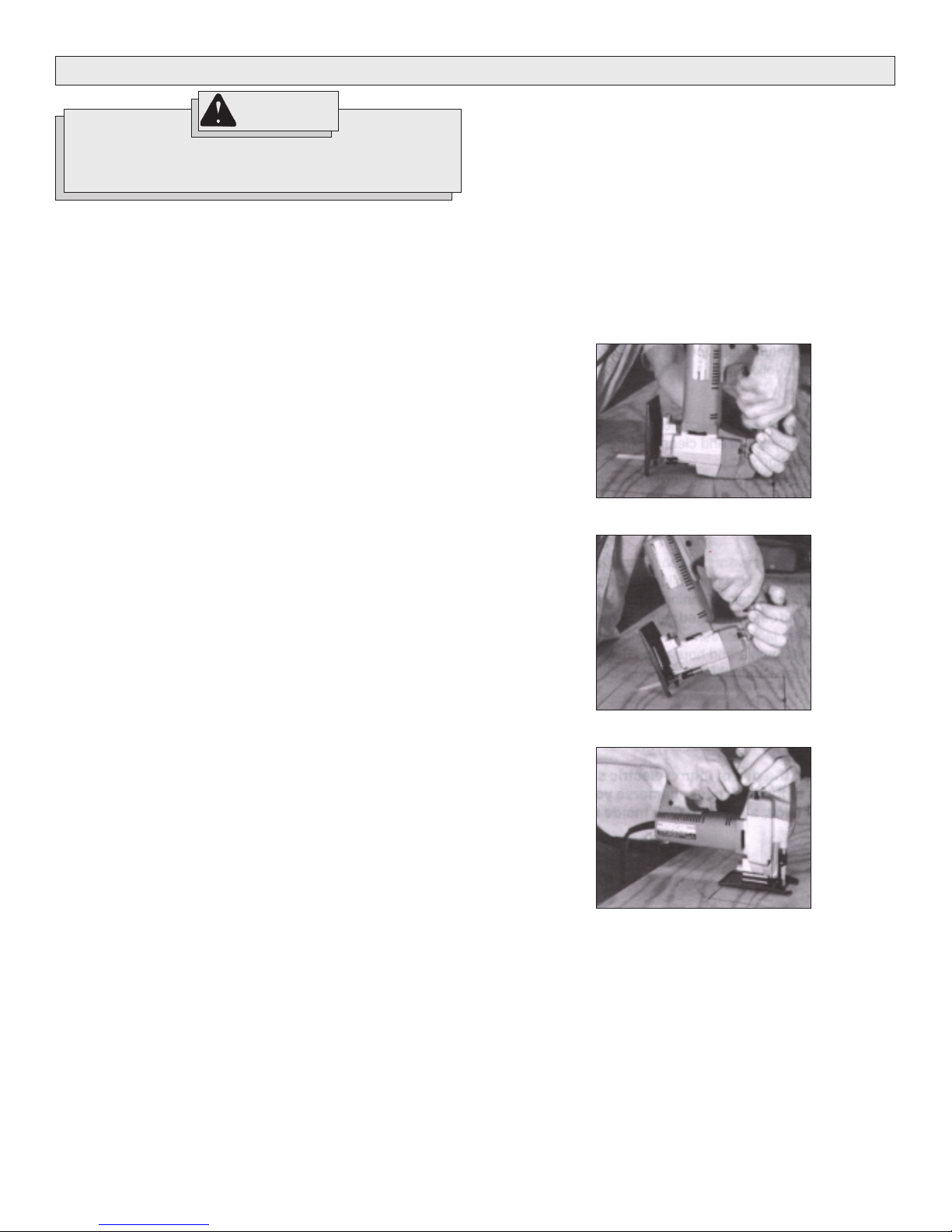
Plunge Cutting (Fig. 3, 4, 5)
Plunge cuts are only made in wood and are begun in the middle of
workpiece without a starting hole. Use same precautions as in blind
cutting.
1. Keep power cord out of cutting area. Hold tool firmly by insulated
surfaces.
2. Place front edge of shoe solidly on workpiece with blade above
scrap or cut-out area (Fig. 3).
3. Using front edge of shoe as pivot, squeeze trigger and gradually
lower blade into workpiece (Fig. 4).
4. When blade has completely penetrated material, complete cut in
usual manner (Fig. 5).
Fig. 3
Fig. 4
Blind Cutting
Blind cutting is done where the back of the surface is not visible. Always
check for hidden hazards such as electrical wiring or water pipes that
may cause fire or electrical shock. Either have these hazards removed
by a qualified person or avoid the area. Always hold your tool by insulated
surfaces.
Pocket Cutting
Pocket cuts are made in the middle of a workpiece.
1. Use the same precautions as in blind cutting.
2. Drill starting hole in scrap area. Insert the blade through the hole and
begin the cut.
An alternate method to pocket cutting is plunge cutting.
Fig. 5
page 6
 Loading...