

Milwaukee 6223 User Manual
BAND SAW
OPERATOR'S MANUAL
MANUEL de L'UTILISATEUR
MANUAL del OPERADOR
Catalog No.
No de Cat.
Catálogo No.
6223
6225
SCIE À RUBAN
SIERRA CLINTA
Catalog No.
No de Cat.
Catálogo No.
6230
6236
DEEP CUT BAND SAW
SCIE À RUBAN PORTATIVE
SIERRAS CLINTA DE CORTE PROFUNDO
TO REDUCE THE RISK OF INJURY, USER MUST READ AND UNDERSTAND OPERATOR'S MANUAL.
AFIN DE RÉDUIRE LE RISQUE DE BLESSURES, L'UTILISATEUR DOIT LIRE ET BIEN COMPRENDRE LE
MANUEL DE L'UTILISATEUR.
PARA REDUCIR EL RIESGO DE LESIONES, EL USUARIO DEBE LEER Y ENTENDER EL MANUAL DEL
OPERADOR.

GENERAL SAFETY RULES
WARNING!
READ AND UNDERSTAND ALL INSTRUCTIONS.
Failure to follow all instructions listed below, may result in
electric shock, fire and/or serious personal injury.
SAVE THESE INSTRUCTIONS.
WORK AREA
1. Keep your work area clean and well lit. Cluttered benches and
dark areas invite accidents.
2. Do not operate power tools in explosive atmospheres, such
as in the presence of flammable liquids, gases, or dust.
Power tools create sparks which may ignite the dust or fumes.
3. Keep bystanders, children, and visitors away while operat-
ing a power tool. Distractions can cause you to lose control.
Protect others in the work area from debris such as chips and
sparks. Provide barriers or shields as needed.
ELECTRICAL SAFETY
4. Grounded tools must be plugged into an outlet properly
installed and grounded in accordance with all codes and
ordinances. Never remove the grounding prong or modify
the plug in any way. Do not use any adaptor plugs. Check
with a qualified electrician if you are in doubt as to whether
the outlet is properly grounded. If the tools should electrically
malfunction or break down, grounding provides a low resistance
path to carry electricity away from the user.
5. Double Insulated tools are equipped with a polarized plug
(one blade is wider than the other). This plug will fit in a
polarized outlet only one way. If the plug does not fit fully in
the outlet, reverse the plug. If it still does not fit, contact a
qualified electrician to install a polarized outlet. Do not change
the plug in any way. Double insulation eliminates the need for
the three wire grounded power cord and grounded power supply
system.
6. Avoid body contact with grounded surfaces such as pipes,
radiators, ranges and refrigerators. There is an increased risk
of electric shock if your body is grounded.
7. Do not expose power tools to rain or wet conditions. Water
entering a power tool will increase the risk of electric shock.
8. Do not abuse the cord. Never use the cord to carry the tools
or pull the plug from an outlet. Keep cord away from heat,
oil, sharp edges or moving parts. Replace damaged cords
immediately. Damaged cords increase the risk of electric shock.
9. When operating a power tool outside, use an outdoor
extension cord marked “W-A” or “W”. These cords are rated
for outdoor use and reduce the risk of electric shock.
PERSONAL SAFETY
10. Stay alert, watch what you are doing, and use common sense
when operating a power tool. Do not use tool while tired or
under the influence of drugs, alcohol, or medication. A
moment of inattention while operating power tools may result in
serious personal injury.
11. Dress properly. Do not wear loose clothing or jewelry.
Contain long hair. Keep your hair, clothing, and gloves away
from moving parts. Loose clothes, jewelry, or long hair can be
caught in moving parts.
12. Avoid accidental starting. Be sure switch is off before
plugging in. Carrying tools with your finger on the switch or
plugging in tools with the switch on invites accidents.
13. Remove adjusting keys or wrenches before turning on the
tool. A wrench or a key that is left attached to a rotating part of the
tool may result in personal injury.
14. Do not overreach. Keep proper footing and balance at all
times. Proper footing and balance enables better control of the tool
in unexpected situations.
15. Use safety equipment. Always wear eye protection. Dust
mask, non-skid safety shoes, hard hat, or hearing protection must
be used for appropriate conditions.
TOOL USE AND CARE
16. Use clamps or other practical way to secure and support
the workpiece to a stable platform. Holding the work by hand
or against your body is unstable and may lead to loss of control.
17. Do not force tool. Use the correct tool for your application.
The correct tool will do the job better and safer at the rate for which
it is designed.
18. Do not use tool if switch does not turn it on or off. Any tool
that cannot be controlled with the switch is dangerous and must be
repaired.
19. Disconnect the plug from the power source before making
any adjustments, changing accessories, or storing the tool.
Such preventive safety measures reduce the risk of starting the tool
accidentally.
20. Store idle tools out of reach of children and other untrained
persons. Tools are dangerous in the hands of untrained users.
21. Maintain tools with care. Keep cutting tools sharp and clean.
Properly maintained tools with sharp cutting edge are less likely to
bind and are easier to control. Do not use a damaged tool. Tag
damaged tools “Do not use” until repaired.
22. Check for misalignment or binding of moving parts, break-
age of parts, and any other condition that may affect the
tool’s operation. If damaged, have the tool serviced before
using. Many accidents are caused by poorly maintained tools.
23. Use only accessories that are recommended by the manufacturer for your model. Accessories that may be suitable for
one tool, may become hazardous when used on another tool.
SERVICE
24. Tool service must be performed only by qualified repair
personnel. Service or maintenance performed by unqualified per-
sonnel could result in a risk of injury.
25. When servicing a tool, use only identical replacement parts.
Follow instructions in the Maintenance section of this
manual. Use of unauthorized parts or failure to follow Maintenance
Instructions may create a risk of electric shock or injury.
page 2
SPECIFIC SAFETY RULES
1. Hold tool by insulated gripping surfaces when performing an operation where the cutting tool may contact hidden wiring or its
own cord. Contact with a “live” wire will make exposed metal parts of tool “live” and shock the operator.
2. Maintain labels and nameplates. These carry important information. If unreadable or missing, contact a
replacement.
3. WARNING! Some dust created by power sanding, sawing, grinding, drilling, and other construction activities contains chemicals known to cause
cancer, birth defects or other reproductive harm. Some examples of these chemicals are:
• lead from lead-based paint
• crystalline silica from bricks and cement and other masonry products, and
• arsenic and chromium from chemically-treated lumber.
Your risk from these exposures varies, depending on how often you do this type of work. To reduce your exposure to these chemicals: work in
a well ventilated area, and work with approved safety equipment, such as those dust masks that are specifically designed to filter out
microscopic particles.
MILWAUKEE
service facility for a free
FPM
Symbology
Canadian Standards
Association
Underwriters
Laboratories, Inc.
Volts Alternating/Direct Current
Volts Alternating Current
No Load Surface Feet per Minute
Amperes
Cat.
No.
6223
6225
6230
6236
Volts
120 AC/DC
120 AC
120 AC
120 AC/DC
Specifications
FPM
200 / 250
200 / 250
0 - 350
250 / 350
Round
Stock
3-1/2"
3-1/2"
4-3/4"
4-3/4"
Capacities
Rectangular
Stock
3-1/2" x 4-1/2"
3-1/2" x 4-1/2"
4-3/4" x 4-3/4"
4-3/4" x 4-3/4"
Recom-
mended
Blades
All
All
Bi-Metal
Bi-Metal
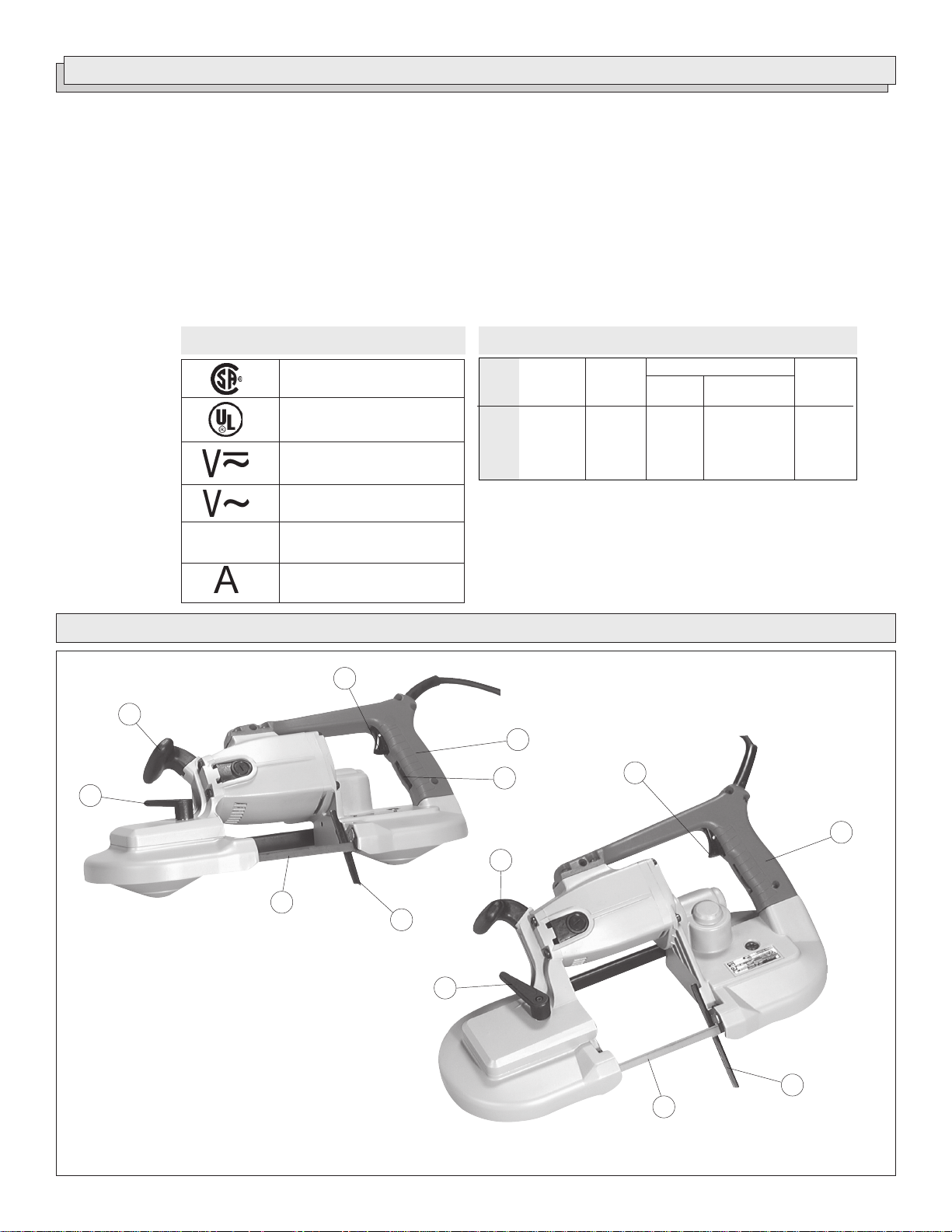
FUNCTIONAL DESCRIPTION
1
7
2
3
6
1
1. Trigger
2. Handle
3. Two-speed switch
4. Work steady rest
5. Blade
6. Tension lock handle
7. Front handle
2
7
5
4
6
4
5
page 3
GROUNDING EXTENSION CORDS
WARNING!
Improperly connecting the grounding wire can
result in the risk of electric shock. Check with a
qualified electrician if you are in doubt as to
whether the outlet is properly grounded. Do not
modify the plug provided with the tool. Never
remove the grounding prong from the plug. Do
not use the tool if the cord or plug is damaged. If
damaged, have it repaired by a
service facility before use. If the plug will not fit
the outlet, have a proper outlet installed by a
qualified electrician.
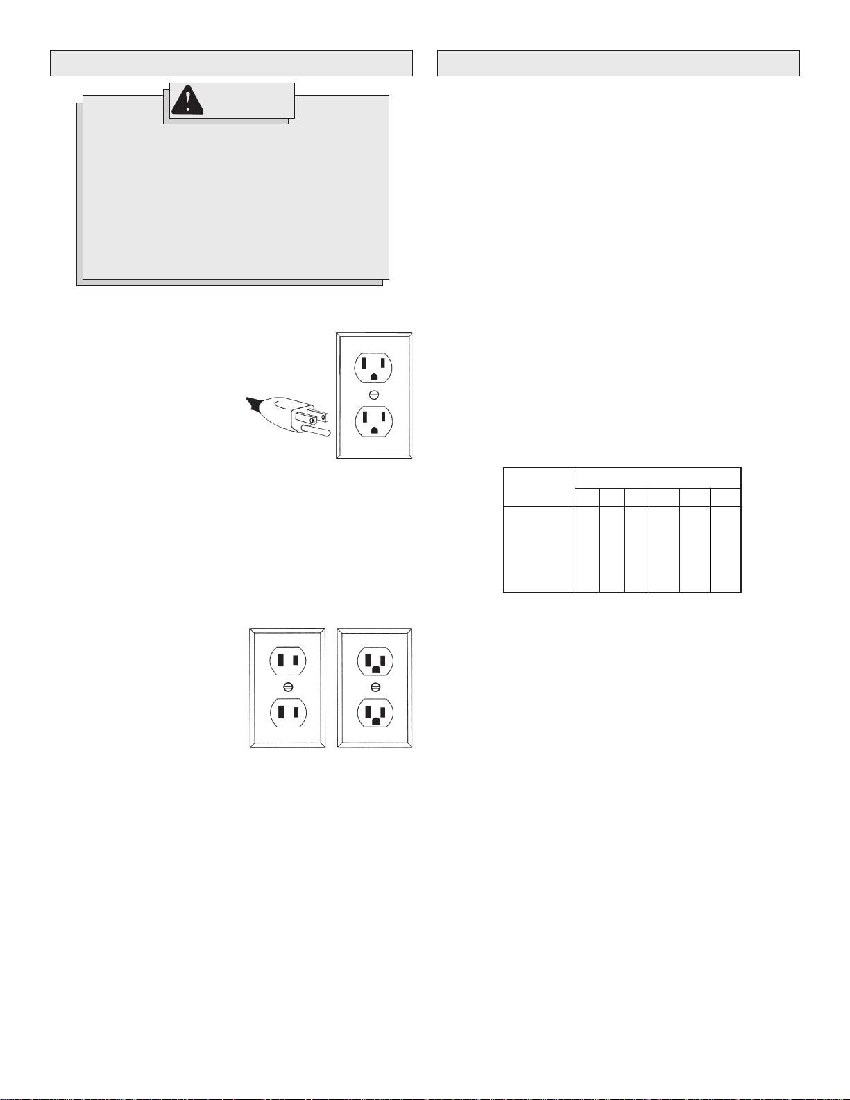
Grounded Tools:
Tools with Three Prong Plugs
Tools marked “Grounding Required”
have a three wire cord and three
prong grounding plug. The plug must
be connected to a properly grounded
outlet (See Figure A). If the tool should
electrically malfunction or break
down, grounding provides a low resistance path to carry electricity
away from the user, reducing the risk
of electric shock.
The grounding prong in the plug is connected through the green wire
inside the cord to the grounding system in the tool. The green wire in the
cord must be the only wire connected to the tool's grounding system and
must never be attached to an electrically “live” terminal.
Your tool must be plugged into an appropriate outlet, properly installed
and grounded in accordance with all codes and ordinances. The plug
and outlet should look like those in Figure A.
MILWAUKEE
Fig. A
Grounded tools require a three wire extension cord. Double insulated
tools can use either a two or three wire extension cord. As the distance
from the supply outlet increases, you must use a heavier gauge extension cord. Using extension cords with inadequately sized wire causes a
serious drop in voltage, resulting in loss of power and possible tool
damage. Refer to the table shown to determine the required minimum
wire size.
The smaller the gauge number of the wire, the greater the capacity of the
cord. For example, a 14 gauge cord can carry a higher current than a 16
gauge cord. When using more than one extension cord to make up the
total length, be sure each cord contains at least the minimum wire size
required. If you are using one extension cord for more than one tool, add
the nameplate amperes and use the sum to determine the required minimum wire size.
Guidelines for Using Extension Cords
• If you are using an extension cord outdoors, be sure it is marked
with the suffix “W-A” (“W” in Canada) to indicate that it is acceptable
for outdoor use.
• Be sure your extension cord is properly wired and in good electrical
condition. Always replace a damaged extension cord or have it
repaired by a qualified person before using it.
• Protect your extension cords from sharp objects, excessive heat
and damp or wet areas.
Recommended Minimum Wire Gauge
Nameplate
Amperes
8.1 - 12
12.1 - 15
15.1 - 20
for Extension Cords*
25'
0 - 5
5.1 - 8
16
16
14
12
10
Extension Cord Length
100'
14
12
10
10
150'
12
10
--
--
--
--
50'
16
16
14
12
10
75'
16
14
12
10
10
200'
12
--
--
--
--
Double Insulated Tools:
Tools with Two Prong Plugs
Tools marked “Double Insulated” do
not require grounding. They have a
special double insulation system
which satisfies OSHA requirements
and complies with the applicable
standards of Underwriters Laboratories, Inc., the Canadian Standard
Association and the National Electrical Code. Double Insulated tools may
be used in either of the 120 volt outlets shown in Figures B and C.
Fig. B
* Based on limiting the line voltage drop to five
volts at 150% of the rated amperes.
READ AND SAVE ALL INSTRUCTIONS
FOR FUTURE USE.
Fig. C
page 4
TOOL ASSEMBLY
WARNING!
To reduce the risk of injury, always unplug
tool before attaching or removing accessories
or making adjustments. Use only specifically
recommended accessories. Others may be
hazardous.
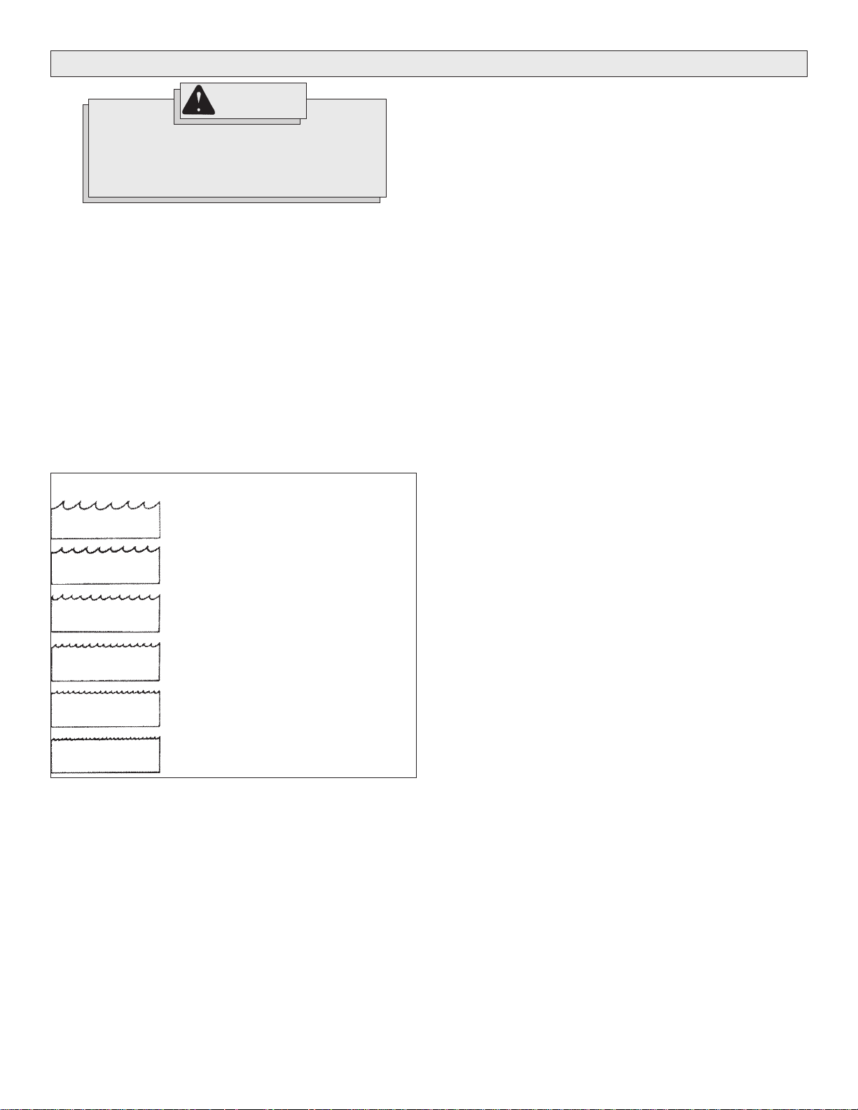
Blades and Blade Selection (Fig. 1)
MILWAUKEE
Every
inch Bi-metal blade which is suitable for most applications. The blade
dimensions required for the band saws are: .020" thickness, 1/2" width
and 44-7/8" in length. The special .020" thickness reduces flexure fatigue and provides maximum tooth life. To maximize cutting life, use a
blade with the correct pitch (teeth per inch) for the specific cutting job.
Blades are available in several pitches. To select the proper blade, three
factors should be considered: The size, shape, and type of material to
be cut.
The following suggestions are for selecting the right blade for various
cutting operations. Keep in mind that these are broad guidelines and that
blade requirements may vary depending upon the specific size, shape
and type of material to be cut. Generally, soft materials require coarse
pitch blades and hard materials require fine pitch blades. Use coarse
pitch blades for thick work and fine pitch blades for thin work. It is
important to keep at least three teeth in the cut (see "Typical Application").
Fig. 1
Portable Bandsaw is furnished with a 14-teeth-per-
Changing Blades
1. UNPLUG THE TOOL BEFORE REMOVING OR INST ALLING BLADES.
2. Turn the tension lock handle located on the front of the saw 180°
counterclockwise. This releases the tension on the blade for easy
removal.
3. Remove the blades from the pulley first and then from the guides.
4. To install a new blade, with the pulleys facing up, insert the blade
between the rollers and the faces of the guides, making sure that
the teeth on the left side of the tool point towards the rear of the tool.
5. With one hand, hold the blade in place between the rollers and the
guides and use the other hand to position the blade around the
pulleys. Be sure that the blade lies freely within the guard channel
before starting the tool motor.
6. Turn the tension lock handle 180° clockwise to lock the position. This
will secure the blade on the pulleys.
BE SURE THAT THE BLADE IS PROPERLY SEATED ON THE
PULLEYS BEFORE STARTING THE CUT.
6 Teeth per Inch
8 Teeth per Inch
10 Teeth per Inch
14 Teeth per Inch
18 Teeth per Inch
24 Teeth per Inch
• For tough stock 1/2" to 3-3/8" in diameter
or width (available in carbon steel only).
• For tough stock 3/8" to 1" in diameter or
width (available in carbon steel only).
• For tough stock 3/16" up to 4-3/4" in
diameter or width.
• For tough stock 5/32" to 3/4" in diameter
or width.
• For thin-wall tubing and thin sheets
heavier than 21 gauge.
• For thin-wall tubing and thin sheets
heavier than 21 gauge.
page 5
OPERATION
WARNING!
To reduce the risk of injury, wear safety goggles
or glasses with side shields. Unplug the tool
before changing accessories or making
adjustments.
Two Speed Switch (Cat. Nos. 6223, 6225, 6236)
MILWAUKEE
switch located below the trigger on the handle. To change speeds, stop
the motor and slide the speed change switch to "HI" or "LO" as indicated
on the tool. For cutting problem materials, use "LO" speed. Never change
from one speed to the other while the motor is running.
Starting, Stopping, and Controlling Speed (Cat. No. 6230)
1. To start the tool, grasp the handle firmly and pull the trigger.
2. To vary the speed, increase or decrease pressure on the trigger.
The further the trigger is pulled, the greater the speed.
3. To select a maximum preset speed at any point within the speed
range, rotate the red knurled knob located on the trigger to the
desired position.
4. To stop the tool, release the trigger. Allow the tool to come to a
complete stop before removing the blade from a partial cut or laying
the tool down.
Two-Speed Band Saws are equipped with a speed change
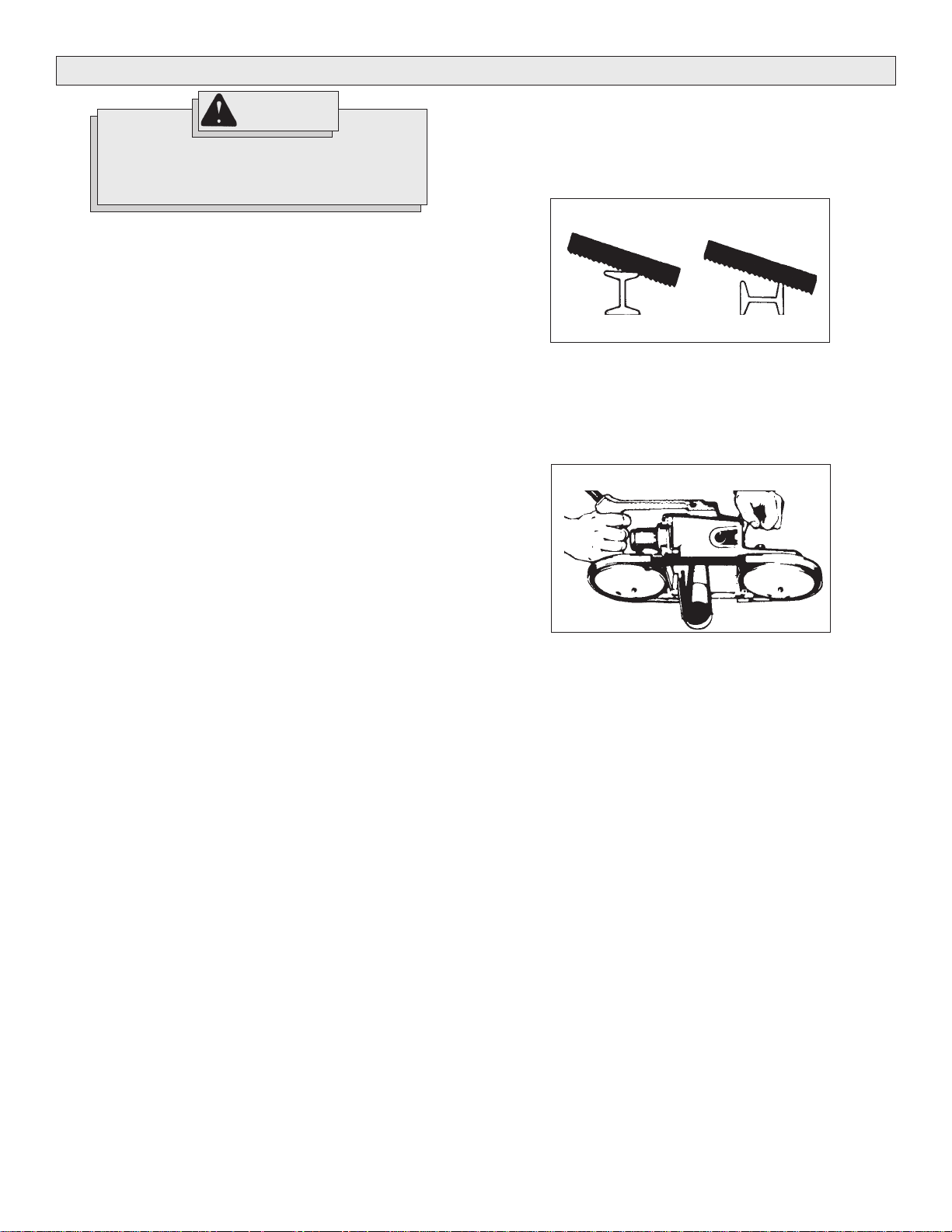
Typical Application (Fig. 2 & 3)
1. Keep the blade off the workpiece until the motor has reached the
selected speed.
2. Start cutting on a surface where the greatest number of teeth will be
in contact with the workpiece at one time (Fig 2).
Fig. 2
Correct Incorrect
3. Place the work steady rest against the workpiece and lower the
moving saw blade into the cut.
4. Do not bear down while cutting. The weight of the tool will supply
adequate pressure for the fastest cutting.
5. When completing a cut, hold the tool firmly so it will not fall against
the workpiece (Fig. 3).
Fig. 3
page 6
 Loading...