

Milwaukee 5625 Operator's Manual
TO REDUCE THE RISK OF INJURY, USER MUST READ OPERATOR'S MANUAL.
AFIN DE RÉDUIRE LE RISQUE DE BLESSURES, L'UTILISATEUR DOIT LIRE LE
MANUEL DE L'UTILISATEUR.
PARA REDUCIR EL RIESGO DE LESIONES, EL USUARIO DEBE LEER EL MANUAL
DEL OPERADOR.
OPERATOR'S MANUAL
MANUEL de L'UTILISATEUR
MANUAL del OPERADOR
HEAVY-DUTY ROUTERS
TOUPIES EXTRA-ROBUSTES
BURILADORAS PARA SERVICIO PESADO
Cat. No.
No de Cat.
5615, 5616, 5619 & 5625 Series
5615, 5616, 5619 & 5625 Série
5615, 5616, 5619 & 5625 Serie

2 3
WORK AREA SAFETY
ELECTRICAL SAFETY
PERSONAL SAFETY
WARNING
READ ALL INSTRUCTIONS
Failure to follow all instructions listed below may result in electric shock, fi re and/or
serious injury. The term "power tool" in all of the warnings listed below refers to your
mains-operated (corded) power tool or battery-operated (cordless) power tool.
SAVE THESE INSTRUCTIONS
GENERAL SAFETY RULES — FOR ALL POWER TOOLS
1. Keep work area clean and well lit.
Cluttered or dark areas invite accidents.
2. Do not operate power tools in ex-
plosive atmospheres, such as in the
presence of fl ammable liquids, gases,
or dust. Power tools create sparks which
may ignite the dust or fumes.
3. Keep children and bystanders away
while operating a power tool. Distractions can cause you to lose control.
4. Power tool plugs must match the
outlet. Never modify the plug in any
way. Do not use any adapter plugs
with earthed (grounded) power tools.
Unmodifi ed plugs and matching outlets
will reduce risk of electric shock.
5. Avoid body contact with earthed or
grounded surfaces such as pipes,
radiators, ranges and refrigerators.
There is an increased risk of electric shock
if your body is earthed or grounded.
6. Do not expose power tools to rain or
wet conditions. Water entering a power
tool will increase the risk of electric
shock.
7. Do not abuse the cord. Never use the
cord for carrying, pulling, or unplugging the power tool. Keep cord away
from heat, oil, sharp edges, or moving parts. Damaged or entangled cords
increase the risk of electric shock.
8. When operating a power tool out-
doors, use an extension cord suitable
for outdoor use. Use of a cord suitable
for outdoor use reduces the risk of electric shock.
9. Stay alert, watch what you are do-
ing and use common sense when
operating a power tool. Do not use
a power tool while you are tired or
under the infl uence of drugs, alcohol
or medication. A moment of inattention
while operating power tools may result
in serious personal injury.
10. Use safety equipment. Always wear
eye protection. Safety equipment such
as dust mask, non-skid safety shoes,
hard hat, or hearing protection used
for appropriate conditions will reduce
personal injuries.
11. Avoid accidental starting. Ensure the
switch is in the off-position before plugging in. Carrying tools with your fi nger on
the switch or plugging in power tools that
have the switch on invites accidents.
12. Remove any adjusting key or wrench
before turning the power tool on. A
wrench or a key left attached to a rotating part of the power tool may result in
personal injury.
13. Do not overreach. Keep proper foot-
ing and balance at all times. This
enables better control of the power tool
in unexpected situations.
14. Dress properly. Do not wear loose
clothing or jewellery. Keep your hair,
clothing and gloves away from moving
parts. Loose clothes, jewellery, or long
hair can be caught in moving parts.
15. If devices are provided for the connec-
tion of dust extraction and collection
facilities, ensure these are connected
and properly used. Use of these de-
vices can reduce dust-related hazards.
POWER TOOL USE AND CARE
16. Do not force the power tool. Use the
correct power tool for your application. The correct power tool will do the
job better and safer at the rate for which
it was designed.
17. Do not use the power tool if the switch
does not turn it on and off. Any power tool
that cannot be controlled with the switch is
dangerous and must be repaired.
18. Disconnect the plug from the power
source and/or the battery pack from
the power tool before making any
adjustments, changing accessories,
or storing power tools. Such preven-
tive safety measures reduce the risk of
starting the tool accidentally.
19. Store idle power tools out of the reach
of children and do not allow persons
unfamiliar with the power tools or
these instructions to operate power
tools. Power tools are dangerous in the
hands of untrained users.
20. Maintain power tools. Check for
misalignment or binding of moving
parts, breakage of parts and any
other condition that may affect the
power tool's operation. If damaged,
have the power tool repaired before
use. Many accidents are caused by
poorly maintained power tools.
21. Keep cutting tools sharp and clean.
Properly maintained cutting tools with
sharp cutting edges are less likely to
bind and are easier to control.
22. Use the power tool, accessories and
tool bits etc., in accordance with
these instructions and in the manner
intended for the particular type of
power tool, taking into account the
working conditions and the work to
be performed. Use of the power tool for
operations different from those intended
could result in a hazardous situation.
SERVICE
23. Have your power tool serviced by a
qualifi ed repair person using only
identical replacement parts. This will
ensure that the safety of the power tool
is maintained.
SPECIFIC SAFETY RULES
1. Hold power tools by insulated grip-
ping surfaces when performing an
operation where the cutting tool may
contact hidden wiring or its own cord.
Contact with a “live” wire will make exposed metal parts of the tool “live” and
shock the operator.
2. Maintain labels and nameplates.
These carry important information. If
unreadable or missing, contact a MIL-
WAUKEE service facility for a free
replacement.
3. Always wear safety goggles and dust
mask. Use only in a well ventilated
area. Using personal safety devices and
in a safe environment reduce the risk for
injury.
4. WARNING! Some dust created by power
sanding, sawing, grinding, drilling, and
other construction activities contains
chemicals known to cause cancer, birth
defects or other reproductive harm.
Some examples of these chemicals
are:
• lead from lead-based paint
• crystalline silica from bricks and cement
and other masonry products, and
• arsenic and chromium from chemicallytreated lumber.
Your risk from these exposures varies,
depending on how often you do this
type of work. T o reduce your exposure to
these chemicals: work in a well ventilated
area, and work with approved safety
equipment, such as those dust masks
that are specifi cally designed to fi lter out
microscopic particles.
5. Some woods contain preservatives
that can be toxic. Take extra care to
prevent inhalation and skin contact when
working with these materials. Request,
and follow, any safety information available from your material supplier.
6. Always make sure the workpiece is free
from nails, screws and other foreign
objects. Keep the working edge away
from the clamping surface. Cutting
these objects can cause loss of control
of the tool and damage to the bit.
7. Never hold the workpiece in one hand
and the tool in the other hand when
using the tool. Never place hands
near or below cutting surface. Clamp-
ing the material and guiding the tool with
both hands is safer.

4 5
8. Never use dull or damaged bits. Sharp
bits must be handled with care. Dam-
aged bits can break during use. Dull bits
require more force to push the tool, which
could cause the bit to break. Damaged
bits can throw carbide pieces and burn
the workpiece.
9. After changing the bit or making any
adjustments, make sure the collet
nut and any other adjustment devices are securely tightened. Loose
adjustment devices can unexpectedly
shift, causing loss of control. Loose
rotating components will be violently
thrown. Watch for vibration or wobbling that could indicate an improperly
installed bit.
10. Maintain fi rm grip on router when start-
ing motor to resist starting torque.
11. Always keep the power supply cord
away from moving parts on the tool.
Keep the cord away from the direction of
the cut.
12. Never start the tool when the bit is in
contact with the material. The bit cutting edge may grab the material causing
loss of control of the tool.
13. Never lay the tool down until the bit
has come to a complete stop. The
spinning bit can grab the surface and pull
the tool out of your control.
14. Never touch the bit during or immedi-
ately after use. After use the bit may be
hot enough to burn bare skin.
15. Use clamps or another practical way
to secure and support the workpiece
to a stable platform. Holding the work
by hand or against your body leaves it unstable and may lead to loss of control.
16. Never clamp the workpiece to a hard
surface, such as concrete or stone.
Contact with the bit could cause the tool
to jump and loss of control.
17. Only operate the routers when held.
Do not clamp or secure the router to
a surface and hold the workpiece by
hand.
18. Never use bits larger than the smallest
of the openings in the base, sub-base,
or dust collection port.
19. Do not loosen or
remove the plunge
base caps. Internal
springs are under
pressure. If loosened or removed, the
plunge base caps and
internal springs will
become projectiles,
which could cause
injury.
Amperes
Double Insulated
Symbology
Canadian Standards
Association
Underwriters
Laboratories, Inc.
Volts Alternating Current
No Load Revolutions
per Minute (RPM)
The grounding prong in the plug is connected
through the green wire inside the cord to the
grounding system in the tool. The green wire
in the cord must be the only wire connected
to the tool's grounding system and must never
be attached to an electrically “live” terminal.
Your tool must be plugged into an appropriate outlet, properly installed and grounded in
accordance with all codes and ordinances.
The plug and outlet should look like those
in Figure A.
Double Insulated Tools:
Tools with Two Prong Plugs
Tools marked “Double Insulated” do not
require grounding. They have a special
double insulation system which satisfies
OSHA requirements and complies with the
applicable standards of Underwriters Labo-
Grounded Tools:
Tools with Three Prong Plugs
Tools marked “Grounding Required” have a
three wire cord and three prong grounding
plug. The plug must be connected to a properly grounded outlet (See Figure A). If the tool
should electrically malfunction or break down,
Fig. B Fig. C
Fig. A
Improperly connecting the grounding
wire can result in the risk of electric
shock. Check with a qualifi ed electri-
cian if you are in doubt as to whether
the outlet is properly grounded. Do not
modify the plug provided with the tool.
Never remove the grounding prong
from the plug. Do not use the tool if the
cord or plug is damaged. If damaged,
have it repaired by a MILW AUKEE service facility before use. If the plug will
not fi t the outlet, have a proper outlet
installed by a qualifi ed electrician.
GROUNDING
WARNING
grounding provides a
low resistance path to
carry electricity away
from the user, reducing the risk of electric
shock.
ratories, Inc., the Canadian Standard Association and the National
Electrical Code. Double
Insulated tools may be
used in either of the 120
volt outlets shown in
Figures B and C.
Grounded tools require a three wire extension
cord. Double insulated tools can use either
a two or three wire extension cord. As the
distance from the supply outlet increases,
you must use a heavier gauge extension cord.
Using extension cords with inadequately sized
wire causes a serious drop in voltage, resulting in loss of power and possible tool damage.
Refer to the table shown to determine the
required minimum wire size.
The smaller the gauge number of the wire,
the greater the capacity of the cord. For
example, a 14 gauge cord can carry a higher
current than a 16 gauge cord. When using
more than one extension cord to make up
the total length, be sure each cord contains
at least the minimum wire size required. If
you are using one extension cord for more
than one tool, add the nameplate amperes
and use the sum to determine the required
minimum wire size.
Guidelines for Using Extension Cords
• If you are using an extension cord outdoors, be sure it is marked with the suffi x
“W-A” (“W” in Canada) to indicate that it
is acceptable for outdoor use.
• Be sure your extension cord is properly wired and in good electrical
condition. Always replace a damaged
extension cord or have it repaired by a
qualifi ed person before using it.
• Protect your extension cords from sharp
objects, excessive heat and damp or wet
areas.
READ AND SAVE ALL
INSTRUCTIONS FOR
FUTURE USE.
Recommended Minimum Wire Gauge
for Extension Cords*
Extension Cord Length
* Based on limiting the line voltage drop to
fi ve volts at 150% of the rated amperes.
Nameplate
Amperes
0 - 2.0
2.1 - 3.4
3.5 - 5.0
5.1 - 7.0
7.1 - 12.0
12.1 - 16.0
16.1 - 20.0
25'
18
18
18
18
16
14
12
75'
18
18
16
14
12
10
100'
18
16
14
12
10
150'
16
14
12
12
50'
18
18
18
16
14
12
10
EXTENSION CORDS
Plunge Base Caps
6 7
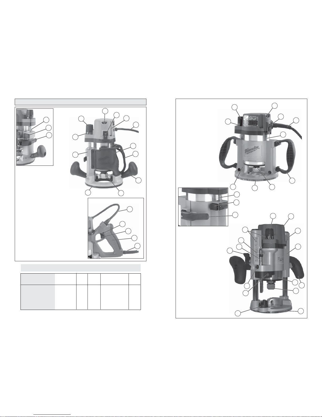
FUNCTIONAL DESCRIPTION
No Load
RPM
24,000
24,000
10,000 - 24,000
10,000 - 24,000
24,000
10,000 - 22,000
Volts
AC
120
120
120
120
120
120
Motor Only
Cat. No.
5615-29
5615-29
5616-29
5616-29
5619-29
5625-29
Specifi cations
Amps
11
11
13
13
11
15
Motor/Base
Cat. No.
5615-20 Bodygrip®
5615-24 Plunge base
5616-20 Bodygrip®
5616-24 Plunge base
5619-20 D-Handle
5625-20 Production
6
2
3
1
Bodygrip® models
5
4
7
8
9
10
11
12
13
14
15
D-Handle models
16
17
9
9
18
1. Depth adjustment screw
2. Motor release button
3. Locking lever
4. Scale
5. Depth adjustment knob
6. Variable speed dial
7. On/Off switch
8. Cord
9. Motor
10. Handle
11. Collet assembly
12. Sub-base
13. Base
11
7
12
4
5
8
9
10
13
6
Production model
1
2
3
1. Depth adjustment screw
2. Motor release button
3. Locking lever
4. Scale
5. Depth adjustment knob
6. Variable speed dial
(For Cat. No. 5616 Series only)
7. On/Off switch
8. Motor
9. Cord
10. Body grip
11. Strap
12. Ball handle
13. Collet assembly
14. Sub-Base
15. Base
16. Lock button
Plunge base models
14. Turret
15. Depth stop rod
release button
16. Depth stop rod
locking screw
17. Plunge release lever
18. Depth stop rod
19. Depth stop rod
adjustable pointer
15
16
14
17
18
19
7
6
9
10
11
12
13
4
5
Max
HP
1-3/4
1-3/4
2-1/4
2-1/4
1-3/4
3-1/2

8 9
TOOL ASSEMBL Y
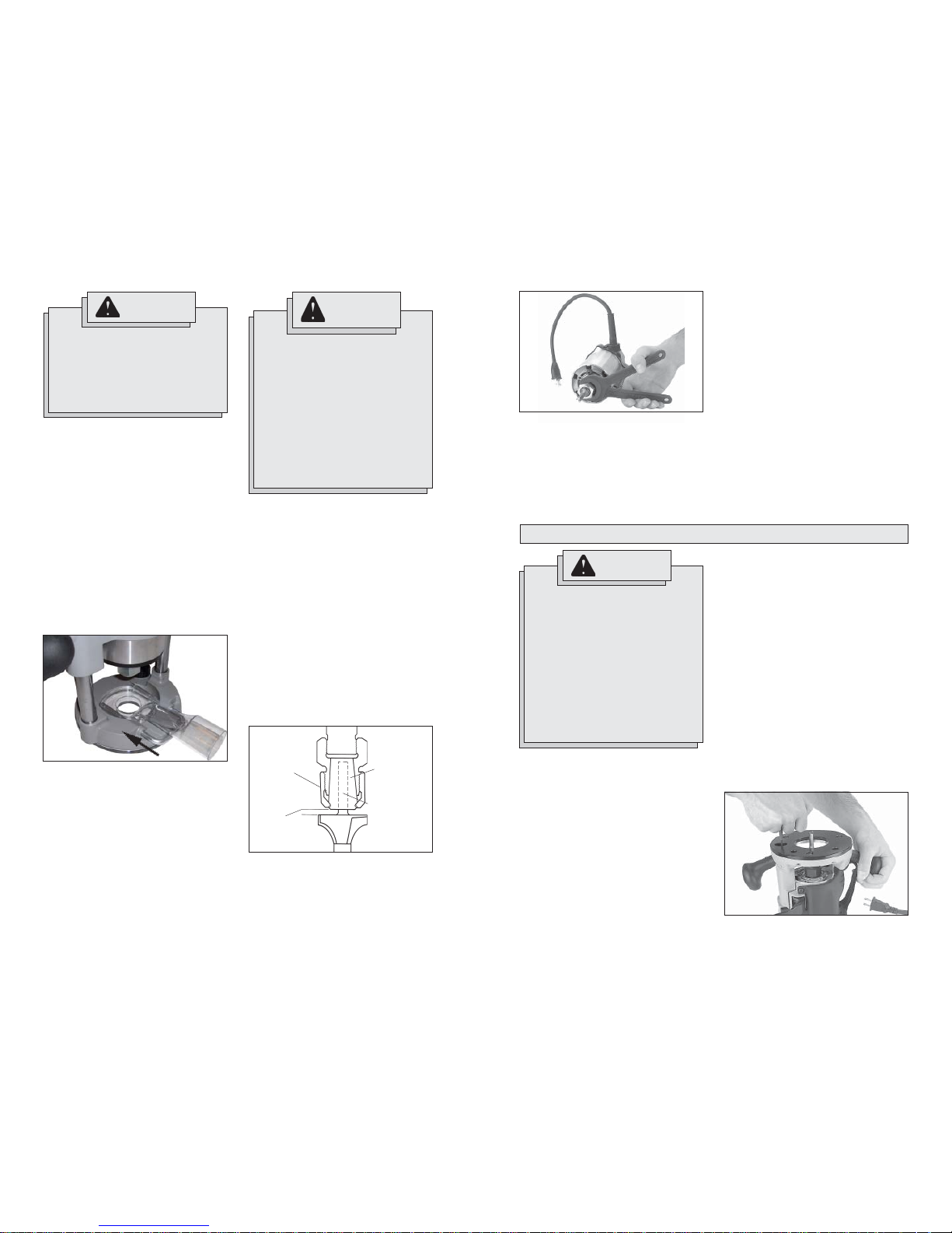
To remove collet from nut, hold nut fi rmly
with one hand and press the collet to one
side with the other hand (Fig. 4).
Collets
The collet must be attached to the collet nut
before it is put into the collet shaft. Be sure
that the size of the collet matches the size
of the bit shank being used. If the wrong
size bit shank is used, the collet may break.
For attaching or detaching the collet nut to
the collet, follow the illustrated instructions
on this page.
Attaching Collet to Collet Nut
To assemble, place the narrow end of the
collet on an even surface. Take the nut and
place it over the collet (Fig. 1).
Position nut squarely over collet with the
smaller opening of the nut facing up (Fig. 2).
Snap nut and collet together by fi rmly apply-
ing downward pressure into assembly with
palm of hand (Fig. 3).
WARNING
To reduce the risk of injury, always
unplug the tool before attaching or
removing accessories or making
adjustments.
Pressing the motor release button
will cause the motor housing to
drop down, which may cause personal injury or damage to the tool or
workpiece. Make sure your hand is
fi rmly on the motor when pressing
the button.
Fig. 1
Fig. 2
Fig. 3
Fig. 4
Fig. 5
1. Unplug the tool. Make sure the locking
lever is fully open.
2. Align the depth adjustment screw on the
motor with the hole on the base.
3. Press and hold the motor release button
and lower the motor into the base to the
desired depth.
NOTE: The plunge base does not have
a motor release button. Release the
locking lever and pull out the motor.
4. Release the motor release button and
push in the locking lever to the fully
closed position.
5. To remove the motor, fully open the
locking lever, grasp the motor, press
and hold the motor release button, and
pull out the motor.
Installing/Removing Sub-bases
Fixed sub-bases (black):
To remove the sub-base, remove the
sub-base screws. To install the sub-base,
secure it with the sub-base screws.
Adjustable sub-bases (clear):
T o ensure the sub-base is centered, use the
centering cone and pin whenever tightening, adjusting, or changing the adjustable
sub-base.
1. Install the sub-base and screws, but do
not tighten them.
2. Lower the motor until the collet is about
1" above the base.
3. With the router upside down, insert the
pin into the cone, then into the collet (see
Fig. 8 for correct orientation). Tighten the
collet.
Installing/Removing Edge Guide
T o install an edge guide, loosen the two rod
screws. Insert the edge guide rods into the
rod holes and tighten the rod screws.
For Cat. Nos. 5615, 5616 and 5619 Series,
see Fig. 6:
Fig. 6
Rod holes
Rod screws
For Cat. No. 5625 Series, see Fig. 7:
Fig. 7
Rod holes
Rod screws
Fig. 8
For
1/4"
Collets
For
1/2"
Collets
Into
Cone
Into
Collet
Installing/Removing the Motor
WARNING
To reduce the risk of injury, DO NOT
use the router if the locking lever
does not hold the motor securely in
the base. If the locking lever becomes
loose, contact a MILWAUKEE service
facility for repairs.
4. Push the cone down fi rmly. The sub-
base will center.
5. While pressing down on the cone,
tighten the sub-base screws.
6. Remove the centering pin from the
collet. Save the pin and cone for future
use.
7. To remove the sub-base, remove the
sub-base screws.
10 11
WARNING
To reduce the risk of injury, wear
safety goggles or glasses with side
shields.
Unplug the tool before changing accessories or making adjustments.
Never make adjustments while the
router is running.
DO NOT use the router if the locking lever does not hold the motor
securely in the base.
NEVER use the Plunge Base Router
models in a router table.
OPERATION
For deeper cuts:
1. Align the "0" on the scale with the arrow
on the tool.
2. Rotate depth adjustment knob clockwise
to desired depth measurement.
For shallower cuts:
1. Align the desired depth measurement
with the arrow on the tool.
2. Rotate depth adjustment knob counterclockwise to "0."
Push in locking lever to fully closed position
when fi nished adjusting.
When using a socket wrench, place the
router upside down on a fl at surface and fully
open the locking lever. Insert a 3/8" socket
wrench into the hole on the base and turn to
desired depth (Fig. 12). Push in locking lever
to fully closed position.
Installing the Bit
It is not necessary to remove the motor from
the base to install a collet assembly or a bit. If
removal of the base is desired, see previous
section. Always remove wood chips, dust or
other foreign materials from the collet shaft
and collet assembly before assembling.
Insert the collet assembly into the collet shaft.
Insert the bit shank into the collet as follows:
1. Unplug the tool.
2. Insert the bit shank into the collet as far
as it will go.
3. Back the bit shank out slightly to avoid
bottoming out.
4. Be sure there is a minimum of 1/16" between the bottom of the collet assembly
and the radius to the cutting portion of
the bit (Fig. 10).
WARNING
To reduce the risk of injury, wear
safety goggles or glasses with side
shields.
Always unplug the tool before attaching or removing accessories or
making adjustments.
Use only specifi cally recommended
accessories. Others may be hazardous.
Never use bits larger than the smallest
of the openings in the base, sub-base,
or dust collection port.
5. Be sure that the collet is not clamped
to a fl uted section on the bit shank. The
collet should be clamped to a solid part
on the bit shank to ensure a tight grip.
T o tighten the bit in the collet assembly, use
two wrenches (Fig. 11).
Removing the Bit
1. Unplug the tool.
2. Loosen the collet nut from the collet shaft
using two wrenches.
3. Once loose, unscrew the collet nut by
hand until it feels tight again.
4. Use the wrenches again until the bit
shank can be pulled out.
Fig. 10
Minimum
1/16"
Bit shank
Collet
Collet nut
Fig. 11
Fig. 12
Templet Guides
A 1-3/16" center hole sub-base is needed to
use a template guide.
To install a templet guide, insert the guide
into the center hole of a 1-3/16" router base
and secure according to the templet guide
instructions.
Fig. 9
WARNING
To reduce the risk of injury , do not use
the dust collection port when plunge
cutting if the bit is larger than the port
opening (1-3/8"). If a rotating router
bit contacts the dust collection port,
the port will break and fl ying debris
may cause injury.
Installing the Dust Collection Port (not
available on the Production model)
1. If an edge guide has been installed, it
must be removed temporarily to install
the dust collection port.
2. Loosen the rod screws.
3. Place the router upright and set the circle
into the base (as shown in Fig. 9).
4. Slide the rods through the base rod
holes and into the port rod holes.
NOTE: Use either the rods supplied with
the dust collection port or rods from a
MILWAUKEE edge guide.
5. Tighten the rod screws.
6. Twist a vacuum hose into the end of the
port.
Adjusting the Depth of Cut
Bodygrip®, D-Handle and Production
models:
The tool depth can be adjusted by using
the depth adjustment knob or a 3/8" socket
wrench with an extension, or the Above-thetable Depth Wrench (Cat. No. 49-96-0370).
When using the depth adjustment knob, fully
open the locking lever and rotate knob to
the desired depth of cut. One revolution of
the depth adjustment knob is equal to 0.2".
For fi ne adjustments less than 5/32", use
the independent scale on the depth adjustment knob.
NOTE: Never tighten a collet assembly
without inserting a bit shank of the proper
size. This may damage the collet.

12 13
Holding the Tool
These tools should be held using both hands
at all times for maximum control.
For Bodygrip® models, see Fig. 14:
Grip the D-handle with one hand and place
the other on the ball handle.
One handle on these bases may be adjusted
to three different positions for maximum
control and comfort.
For Plunge Base and Production models,
see Fig. 16:
You can hold this tool using the body grip
and ball handle or both ball handles. The
body grip features an adjustable strap, which
can be attached in two different positions for
maximum control and comfort.
One handle on these bases may be adjusted
to three different positions for maximum
control and comfort.
For D-Handle models, see Fig. 15:
WARNING
To reduce the risk of injury, wear
safety goggles or glasses with side
shields.
To reduce the risk of injury, keep
hands, body and cord away from the
bit and all moving parts.
Before plugging the tool into a power
outlet, make sure the on/off switch is
in the "O" position.
Starting and Stopping Router Motor
For Cat. Nos. 5615, 5616 & 5625 Series:
1. To start the motor, place the router so the
bit is away from you and not in contact
with the workpiece. Grasp the tool fi rmly
and push the On/Off switch to the "I"
position.
2. To stop the motor, place the router so
the bit is away from you and push the
On/Off switch to the "O" position. Hold
the tool until the bit stops turning.
For Cat. No. 5619 Series:
1. Push the On/Off switch to the "I" position.
2. T o start the motor, place the router so the
bit is away from you and not in contact
with the workpiece. Grasp the tool fi rmly
and pull the trigger.
3. To stop the motor, release the trigger.
Locking the D-handle Base Trigger
1. To lock the trigger, hold in the lock
button while pulling the trigger. Release
the trigger.
2. To unlock the trigger , pull the trigger and
release. The lock button will pop out.
NOTE: D-handle base does not fi t with Cat.
No. 5625 Series base.
Fig. 17
Lock button
Fig. 18
The Soft-Start feature reduces the amount
of torque reaction to the tool and the user.
This feature gradually increases the motor
speed up from zero to the speed set by the
variable speed dial.
Feedback Control (For Cat. Nos. 5616 &
5625 Series only)
The electronic speed control system allows
the tool to maintain constant speed between
no-load and load conditions.
Electronic Overload Protection
(For Cat. Nos. 5616 & 5625 Series only)
These tools are equipped with an electronic
overload protection feature.
If the motor shuts off during use, remove the
bit from the workpiece and push the On/Off
switch to the "O" position for three (3) seconds. This will reset the electronics in the
tool. The tool can then be restarted.
Using the Variable Speed Dial
(For Cat. Nos. 5616 & 5625 Series only)
The variable speed dial allows the user to
adjust the rotating speed (RPM) of the tool.
Variable speed dial settings range from
numbers (7) seven through (1) one. Higher
numbers correspond to higher speeds and
lower number correspond to lower speeds.
T o change the speed, set the variable speed
control dial to the desired number (Fig 18).
Soft Start (For Cat. Nos. 5616 & 5625
Series only)
Plunge base models:
1. Unplug the tool.
2. Install the bit.
3. Press the plunge release lever and push
down on the handles until the bit touches
the workpiece.
4. Loosen the depth stop rod locking
screw.
5. Turn the turret so the full depth position
is directly below the rod
6. Press the depth stop rod release button
to lower the rod. It should rest on the full
depth position of the turret.
7. Place the adjustable pointer on "0".
8. Press in the depth stop rod release
button Move the rod up to the desired
depth of cut.
9. Use the depth adjustment knob to fi nely
tune the depth of cut.
10. Tighten the depth stop rod locking
screw.
11. To obtain the cut making multiple
passes, rotate the turret to a higher step.
Each step is 1/8"
NOTE: A fi ne fi nish can be made using the
turret and multiple passes.
full
depth
position
1/8"
1/4"
3/8"
1/2"
5/8"
Depth stop rod
Fig. 13
Fig. 14
Fig. 15
Fig. 16
Alternate
strap
positions
Alternate
handle
positions
Turret
WARNING
To reduce the risk of injury, NEVER
use the Plunge Base Router models
in a router table.

14 15
When working on an inside edge, move the
router in a clockwise direction (Fig. 20).
Moving the router in the opposite direction is
known as "climb cutting."
Fig. 20
Direction
of feed
WARNING
To reduce the risk of injury, avoid
"climb cutting." Climb cutting
increases the potential for loss of
control of the tool and damage to the
workpiece. If climb cutting can not be
avoided, use extreme caution.
WARNING
To reduce the risk of injury, always
wear eye protection.
To reduce the risk of explosion,
electric shock and property damage, always check the work area
for hidden pipes and wires before
routing.
Making the Cut
Before cutting, check that all adjustments
are tight and the locking lever is fully closed
and secure.
The speed and depth of cut will depend
largely on the type of material being worked.
Keep the cutting pressure constant but do
not use excessive force on the router so the
motor speed slows excessively. It may be
necessary on exceptionally hard woods or
problem materials to make more than one
pass to get the desired depth of cut.
Before beginning the cut on the actual workpiece, make a sample cut on a scrap piece
of lumber. This will show you exactly how the
cut will look as well as enable you to check
dimensions. Always be sure the workpiece is
secure before routing. When routing edges,
the router should be held fi rmly down and
against the work using handles.
Since the cutter rotates clockwise, more
effi cient cutting will be obtained if the router
is moved from left to right as you stand
facing the work. The arrows on the base of
the tool indicate the direction of bit rotation.
When working on the outside of an edge,
move router in a counterclockwise direction
(Fig. 19).
Fig. 19
Bit rotation
Router feed
Top view
Work
Maintaining Tools
Keep your tool in good repair by adopting a
regular maintenance program. Before use,
examine the general condition of your tool.
Inspect guards, switches, tool cord set and
extension cord for damage. Check for loose
screws, misalignment, binding of moving
parts, improper mounting, broken parts and
any other condition that may affect its safe
operation. If abnormal noise or vibration occurs, turn the tool off immediately and have
the problem corrected before further use.
Do not use a damaged tool. Tag damaged
tools “DO NOT USE” until repaired (see
“Repairs”).
Under normal conditions, relubrication is not
necessary until the motor brushes need to
be replaced. After six months to one year,
depending on use, return your tool to the
nearest MILWAUKEE service facility for the
following:
• Lubrication
• Brush inspection and replacement
• Mechanical inspection and cleaning
(gears, spindles, bearings, housing,
etc.)
• Electrical inspection (switch, cord,
armature, etc.)
• Testing to assure proper mechanical and
electrical operation
WARNING
To reduce the risk of injury , always unplug your tool before performing any
maintenance. Never disassemble the
tool or try to do any rewiring on the
tool's electrical system. Contact a
MILWAUKEE service facility for ALL
repairs.
WARNING
To reduce the risk of injury, electric
shock and damage to the tool, never
immerse your tool in liquid or allow a
liquid to fl ow inside the tool.
MAINTENANCE
Cleaning
Clean dust and debris from vents. Keep
the tool handles clean, dry and free of oil
or grease. Use only mild soap and a damp
cloth to clean your tool since certain cleaning
agents and solvents are harmful to plastics
and other insulated parts. Some of these
include: gasoline, turpentine, lacquer thinner,
paint thinner, chlorinated cleaning solvents,
ammonia and household detergents containing ammonia. Never use fl ammable or
combustible solvents around tools.
Repairs
If your tool is damaged, return the entire tool
to the nearest service center.
ACCESSORIES
Always remove battery pack before
changing or removing accessories.
Only use accessories specifi cally
recommended for this tool. Others
may be hazardous.
WARNING
For a complete listing of accessories refer to
your MILWAUKEE Electric T ool catalog or go
on-line to www.milwaukeetool.com. T o obtain
a catalog, contact your local distributor or a
service center listed on the back cover of this
operator’s manual.
Above-the-table Depth Wrench
Cat. No. 49-96-0370
3/8" Hex drive wrench for use with above-
the-table depth adjustment system.
Collet Wrench (1-1/8")
Cat. No. 49-96-0365
Plunge Cutting
1. Set the depth of cut.
2. Securely clamp the workpiece.
3. Press the plunge release lever and raise
the bit so it does not contact the workpiece.
4. Hold the handles securely and turn on
the motor. Wait for the motor to reach
full speed (or the speed indicated by the
variable speed dial).
5. Press the plunge release lever and
slowly lower the bit into the workpiece
until the depth stop rod contacts the turret. Release the plunge release lever.
6. Begin moving the router, keeping the
sub-base fl at on the workpiece. Keep
the cord and dust collection hose out of
the path of the router.
7. When fi nished, press the plunge release
lever and raise the bit out of the workpiece. Turn the motor off and wait for the
bit to stop turning.
WARNING
To reduce the risk of injury, do not
use a plunge base router if the motor
does not rise automatically when the
plunge release lever is pressed.

16 17
FIVE YEAR TOOL LIMITED WARRANTY
SÉCURITÉ DU LIEU
DE TRAVAIL
AVERTISSEMENT
LIRE SOIGNEUSEMENT TOUTES LES INSTRUCTIONS
Le non respect des instructions ci-après peut entraîner des chocs électriques, des
incendies et/ou des blessures graves. Le terme «outil électrique» fi gurant dans les
avertissements ci-dessous renvoie à l’outil électrique à alimentation par le réseau
(à cordon) ou par batterie (sans fi l).
CONSERVER CES INSTRUCTIONS
RÈGLES GÉNÉRALES DE SÉCURITÉ POUR
LES OUTILS ÉLECTRIQUE
1. Maintenir la zone de travail propre et
bien éclairée. Les zones encombrées
ou mal éclairées sont favorables aux
accidents.
2. Ne pas utiliser d’outil électrique dans
une atmosphère explosive, telle
qu’en en présence de liquides, de
gaz ou de poussières infl ammables.
Les outils électriques génèrent des
étincelles qui peuvent enfl ammer les
poussières ou les fumées.
3. Tenir les enfants et les personnes
non autorisées à l’écart pendant le
fonctionnement d’un outil électrique.
Un manque d’attention de l’opérateur
risque de lui faire perdre le contrôle de
l’outil.
4. La fi che de l’outil électrique doit cor-
respondre à la prise d’alimentation.
Ne jamais modifier la fiche d’une
manière quelconque. Ne pas utiliser
d’adaptateur avec les outils électriques mis à la terre (à la masse).
Des fi ches non modifi ées et des prises
d’alimentation assorties réduisent le
risque de choc électrique.
5. Éviter tout contact corporel avec des
surfaces reliées à la masse ou à la
terre telles que tuyaux, radiateurs,
cuisinières et réfrigérateurs. Un risque
de choc électrique plus élevé existe si le
corps est relié à la masse ou à la terre.
6. Ne pas exposer les outils électriques
à la pluie ou à l’humidité. Le risque de
choc électrique augmente si de l’eau
s’infi ltre dans un outil électrique.
9. Être sur ses gardes, être attentif et
faire preuve de bon sens en utilisant
un outil électrique. Ne pas utiliser
un outil électrique en cas de fatigue
ou sous l’influence de drogues,
d’alcool ou de médicaments. Un
instant d’inattention lors de l’utilisation
d’un outil électrique peut entraîner des
blessures graves.
10. Utiliser un équipement de sécurité.
Toujours porter des lunettes de protection. Un équipement de sécurité
comprenant masque anti-poussière,
chaussures de sécurité anti-dérapantes,
casque ou dispositif de protection antibruit peut, dans les circonstances appropriées, réduire le risque de blessure.
11. Éviter tout démarrage accidentel de
l’outil. S’assurer que le commutateur
est en position OFF (Arrêt) avant de
brancher l’outil. Le port de l’outil avec
un doigt sur le commutateur ou son
branchement avec le commutateur en
position ON (Marche) sont favorables
aux accidents.
7. Prendre soin du cordon. Ne jamais
utiliser le cordon pour transporter,
tirer ou débrancher l’outil électrique.
Tenir le cordon à l’écart de la chaleur ,
des huiles, des arêtes coupantes ou
des pièces en mouvement. Un cordon
endommagé ou emmêlé présente un
risque accru de choc électrique.
8. Se procurer un cordon d’alimentation
approprié en cas d’utilisation
d’un outil électrique à l’extérieur.
L’utilisation d’un cordon d’alimentation
pour usage extérieur réduit le risque de
choc électrique.
SÉCURITÉ INDIVIDUELLE
SÉCURITÉ ÉLECTRIQUE
Every MILWAUKEE electric power tool (including battery charger) is warranted to the original
purchaser only to be free from defects in material and workmanship. Subject to certain exceptions, MILWAUKEE will repair or replace any part on an electric power tool which, after
examination, is determined by MILWAUKEE to be defective in material or workmanship for
a period of fi ve (5) years* after the date of purchase. Return the electric power tool and a
copy of proof of purchase to a MILWAUKEE factory Service/Sales Support Branch location
or MILWAUKEE Authorized Service Station, freight prepaid and insured. This warranty does
not apply to damage that MILWAUKEE determines to be from repairs made or attempted by
anyone other than MILWAUKEE authorized personnel, misuse, alterations, abuse, normal
wear and tear, lack of maintenance, or accidents.
* The warranty period for Hoists (lever, hand chain, & electric chain hoists), Ni-Cd battery
packs, Work Lights (cordless fl ashlights), Job Site Radios, and Trade Titan™ Industrial Work
Carts is one (1) year from the date of purchase.
*There is a separate warranty for V™-technology Li-Ion Battery Packs 18 volts or above that
accompany the power tools:
*Every MILWAUKEE V™-technology Li-Ion Battery Pack 18 volts or above is covered by an
initial 1000 Charges/2 Years free replacement warranty. This means that for the earlier of
the fi rst 1000 charges or two (2) years from the date of purchase/fi rst charge, a replacement
battery will be provided to the customer for any defective battery free of charge. Thereafter,
customers will also receive an additional warranty on a pro rata basis up to the earlier of the
fi rst 2000 charges or fi ve (5) Years from the date of purchase/fi rst charge. This means that
every customer gets an additional 1000 charges or three (3) years of pro rata warranty on
the V™-technology Li-Ion Battery Pack 18 volts or above depending upon the amount of use.
During this additional warranty period, the customer pays for only the useable service received
over and above the fi rst 1000 Charges/2 years, based on the date of fi rst charge and number
of charges found on the battery pack via Milwaukee’s V™-technology Service Reader.
Warranty Registration is not necessary to obtain the applicable warranty on a MILWAUKEE
product. However, proof of purchase in the form of a sales receipt or other information deemed
suffi cient by MILWAUKEE is requested.
ACCEPTANCE OF THE EXCLUSIVE REPAIR AND REPLACEMENT REMEDIES DESCRIBED HEREIN IS A CONDITION OF THE CONTRACT FOR THE PURCHASE OF
EVERY MILWAUKEE PRODUCT. IF YOU DO NOT AGREE TO THIS CONDITION, YOU
SHOULD NOT PURCHASE THE PRODUCT. IN NO EVENT SHALL MILWAUKEE BE LI-
ABLE FOR ANY INCIDENTAL, SPECIAL, CONSEQUENTIAL OR PUNITIVE DAMAGES,
OR FOR ANY COSTS, ATTORNEY FEES, EXPENSES, LOSSES OR DELAYS ALLEGED
TO BE AS A CONSEQUENCE OF ANY DAMAGE TO, FAILURE OF, OR DEFECT IN ANY
PRODUCT INCLUDING, BUT NOT LIMITED TO, ANY CLAIMS FOR LOSS OF PROFITS.
THIS WARRANTY IS EXCLUSIVE AND IN LIEU OF ALL OTHER WARRANTIES OR CONDITIONS, WRITTEN OR ORAL, EXPRESSED OR IMPLIED. WITHOUT LIMITING THE
GENERALITY OF THE FOREGOING, MILWAUKEE DISCLAIMS ANY IMPLIED W ARRANTY
OF MERCHANTABILITY OR FITNESS FOR A PARTICULAR USE OR PURPOSE, AND ALL
OTHER WARRANTIES.
This warranty applies to product sold in the U.S.A., Canada and Mexico only.
 Loading...