

Milwaukee 5376-20 User Manual
1
2
39
38
4a
SPECIFY CATALOG NO. AND SERIAL NO. WHEN ORDERING PARTS
2
CATALOG NO.
3
4b
4
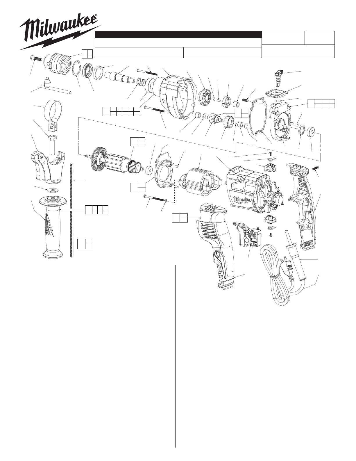
SERVICE PARTS LIST
1/2" SINGLE SPEED HAMMER-DRILL
5376-20
4c 4d 5 4g
4e
4f
4a 4b 4c 4d 4e
4f 4g 4h 4j 4k
SERIAL
NUMBER
4j
4h
7
8
D20A
11a
12
11b
12a
12b
REVISED BULLETIN
WIRING INSTRUCTION
13
BULLETIN NO.
54-24-3660
Aug. 2012
See page 3
14
15
16
11
17
DATE
11a 11b 11c
11d 11e
37
19a
19b
20a
20b
42
19b
43
19
35
34
FIG. PART NO. DESCRIPTION OF PART NO. REQ.
1 05-88-1500 M6 x 1.0 x 27mm LH Screw (1)
2 48-66-3280 1/2" Chuck Key (1)
3 48-66-1355 1/2" Keyed Chuck (1)
4 28-14-5377 Gearcase Assembly (1)
4a 34-80-5380 Retaining Ring (1)
4b --------------- Oil Seal (1)
4c --------------- Plastic Ring (1)
4d --------------- Spindle (1)
4e --------------- Return Spring (1)
4f --------------- Ball Bearing (1)
4g --------------- Gearcase (1)
4h --------------- 2nd Stage Gear with Rotating Clutch (1)
4j --------------- Bushing (1)
4k --------------- Needle Bearing (1)
5 06-81-5380 M4 x 52 Pan Hd. ST T-20 Screw (2)
6 06-81-5383 M4 x 35 Pan Hd. ST T-20 Screw (1)
7 02-02-5380 Steel Ball (1)
8 44-60-5381 Pin (1)
9 43-44-5376 Rubber Gasket (1)
10 45-88-5381 Washer (1)
11 28-28-5376 Diaphragm Assembly (1)
11a --------------- Fixed Clutch (1)
11b --------------- Needle Bearing (1)
11c --------------- Washer (1)
11d --------------- Needle Bearing (1)
11e --------------- Diaphragm (1)
12 14-29-5376 Gear Shaft Assembly (1)
12a --------------- Gear Shaft (1)
12b --------------- 1st Reduction Gear (1)
13 44-70-5376 Spring Plunger (1)
14 44-10-5376 Selector Lever / Impact Pin Assembly (1)
15 42-92-5376 Selector Plate (1)
16 34-40-5376 O-Ring (1)
17 42-34-5380 Rubber Knock (1)
18 43-44-5377 Rubber Seal Ring (1)
19 16-07-5376 Armature Assembly (1)
19a 02-04-5381 Ball Bearing (1)
19b 02-04-5382 Ball Bearing (1)
20 14-34-5383 Fan Baffl e Assembly (1)
20a --------------- Baffl e (1)
20b --------------- Rubber Knock (2)
36
20
34 35 36
40
37 38 39
EXAMPLE:
00
Component Parts (Small #)
0
Are Included When Ordering
The Assembly (Large #).
6
4k
20a
10
12a
12b
20b
21
22
29a
29
29b
FIG. PART NO. DESCRIPTION OF PART NO. REQ.
21 18-07-5376 Field (1)
22 31-50-5378 Motor Housing (1)
23 02-02-0165 Steel Ball (1)
24 06-81-5381 M3 x 6mm Pan Hd. Phillips ST Screw (2)
25 44-66-5379 Pressure Plate (2)
26 22-22-5380 Self-Stop Carbon Brush Assembly (1)
27 22-22-5381 Carbon Brush Assembly (1)
28 23-66-5380 Switch (1)
29 14-34-5378 Rear Handle Assembly (1)
29a --------------- Handle Halve - Left (1)
29b --------------- Handle Halve - Right (1)
30 05-88-1200 M4 x 16mm Pan Hd. ST T-20 Screw (7)
32 44-76-0210 Cord Protector (1)
33 22-64-0216 Power Cord (1)
34 31-05-5383 Side Handle (1)
35 45-88-5377 Steel Washer (1)
36 44-94-5381 Depth Gauge (1)
37 14-34-5374 Side Handle Carrier Assembly (1)
38 05-81-5376 M8 x 53mm Screw (1)
39 40-50-5375 Side Handle Clamping Band (1)
40 14-34-5388 Side Handle Assembly (1)
41 12-20-5379 Service Nameplate (Not Shown) (1)
42 06-81-5385 Field Screw (2)
43 45-88-5400 Field Washer (2)
48-66-4040 Chuck Key Holder (Not Shown) (1)
23-94-5381 Red Brush Leadwire Assy. (Not Shown) (1)
23-94-5379 Black Brush Leadwire Assy. (Not Shown) (1)
24
23
25
11d
28
29a
26
11c
9
11e
18
19a
30
29b
32
33
MILWAUKEE ELECTRIC TOOL CORPORATION
13135 W. LISBON RD., BROOKFIELD, WI 53005
Drwg. 4
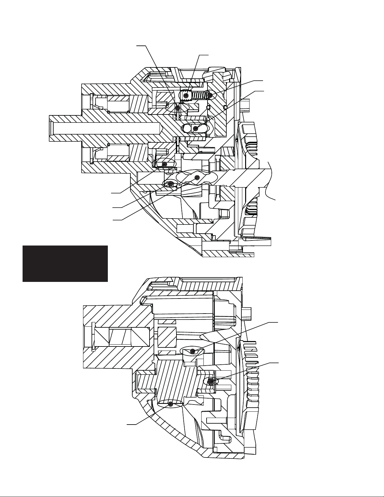
Lubrication Notes:
Use Milwaukee 'P' Grease
Cat. No. 49-08-4250
Brush 1g of grease
onto both clutch teeth
Coat all gear teeth with grease
Add a drop of purple Loctite® 222 here
Brush grease here
Place grease here
Coat this area with grease
Coat this area of the
armature shaft with grease
When servicing, remove 90-95%
of the existing grease prior to
installing Type 'P' grease.
Original grease maybe similar in
color but not compatible with 'P'.
Place a heavy coating of
grease on all gear teeth
Place grease in this area
Place a heavy coating of grease
on all the gear shaft assembly teeth
 Loading...