

Milwaukee 5315-21, 5315-22, 5319-21, 5321-21, 5321-22 Operator's Manual

OPERATOR'S MANUAL
MANUEL de L'UTILISATEUR
MANUAL del OPERADOR
Catalog No.
No de Cat.
Catálogo No.
5315-21, 5315-22
5319-21
5321-21, 5321-22
SDS
max
1-1/2" HEAVY-DUTY ROTARY HAMMERS
EXTRA ROBUSTES MARTEAUX ROTATIFS 40 mm (1-1/2")
ROTOMARTILLOS HEAVY-DUTY 40 mm (1-1/2")
TO REDUCE THE RISK OF INJURY, USER MUST READ OPERATOR'S MANUAL.
AFIN DE RÉDUIRE LE RISQUE DE BLESSURES, L'UTILISATEUR DOIT LIRE LE MANUEL DE L'UTILISATEUR.
PARA REDUCIR EL RIESGO DE LESIONES, EL USUARIO DEBE LEER EL MANUAL DEL OPERADOR.

GENERAL SAFETY RULES — FOR ALL POWER TOOLS
WARNING
Failure to follow all instructions listed below may result in electric shock, fi re and/or serious injury. The term "power tool" in all of the
warnings listed below refers to your mains-operated (corded) power tool or battery-opearted (cordless) power tool.
SAVE THESE INSTRUCTIONS
READ ALL INSTRUCTIONS
WORK AREA SAFETY
1. Keep work area clean and well lit. Cluttered or dark areas invite accidents.
2. Do not operate power tools in explosive atmospheres, such as
in the presence of fl ammable liquids, gases, or dust. Power tools
create sparks which may ignite the dust or fumes.
3. Keep children and bystanders away while operating a power tool.
Distractions can cause you to lose control.
ELECTRICAL SAFETY
4. Power tool plugs must match the outlet. Never modify the plug in
any way. Do not use any adapter plugs with earthed (grounded)
power tools. Unmodifi ed plugs and matching outlets will reduce risk
of electric shock.
5. Avoid body contact with earthed or grounded surfaces such as
pipes, radiators, ranges and refrigerators. There is an increased risk
of electric shock if your body is earthed or grounded.
6. Do not expose power tools to rain or wet conditions. Water entering
a power tool will increase the risk of electric shock.
7. Do not abuse the cord. Never use the cord for carrying, pulling, or
unplugging the power tool. Keep cord away from heat, oil, sharp
edges, or moving parts. Damaged or entangled cords increase the
risk of electric shock.
8. When operating a power tool outdoors, use an extension cord suit-
able for outdoor use. Use of a cord suitable for outdoor use reduces
the risk of electric shock.
PERSONAL SAFETY
9. Stay alert, watch what you are doing and use common sense when
operating a power tool. Do not use a power tool while you are tired
or under the infl uence of drugs, alcohol or medication. A moment
of inattention while operating power tools may result in serious personal
injury.
10. Use safety equipment. Always wear eye protection. Safety equip-
ment such as dust mask, non-skid safety shoes, hard hat, or hearing
protection used for appropriate conditions will reduce personal injuries.
11. Avoid accidental starting. Ensure the switch is in the off-position
before plugging in. Carrying tools with your fi nger on the switch or
plugging in power tools that have the switch on invites accidents.
12. Remove any adjusting key or wrench before turning the power
tool on. A wrench or a key left attached to a rotating part of the power
tool may result in personal injury.
13. Do not overreach. Keep proper footing and balance at all times. This
enables better control of the power tool in unexpected situations.
14. Dress properly. Do not wear loose clothing or jewellery. Keep your
hair, clothing and gloves away from moving parts. Loose clothes,
jewellery, or long hair can be caught in moving parts.
15. If devices are provided for the connection of dust extraction and
collection facilities, ensure these are connected and properly used.
Use of these devices can reduce dust-related hazards.
16. Do not force the power tool. Use the correct power tool for your
application. The correct power tool will do the job better and safer at
the rate for which it was designed.
17. Do not use the power tool if the switch does not turn it on and off.
Any power tool that cannot be controlled with the switch is dangerous
and must be repaired.
18. Disconnect the plug from the power source and/or the battery pack
from the power tool before making any adjustments, changing accessories, or storing power tools. Such preventive safety measures
reduce the risk of starting the tool accidentally.
19. Store idle power tools out of the reach of children and do not al-
low persons unfamiliar with the power tools or these instructions
to operate power tools. Power tools are dangerous in the hands of
untrained users.
20. Maintain power tools. Check for misalignment or binding of moving
parts, breakage of parts and any other condition that may affect the
power tool's operation. If damaged, have the power tool repaired
before use. Many accidents are caused by poorly maintained power
tools.
21. Keep cutting tools sharp and clean. Properly maintained cutting
tools with sharp cutting edges are less likely to bind and are easier to
control.
22. Use the power tool, accessories and tool bits etc., in accordance
with these instructions and in the manner intended for the particular type of power tool, taking into account the working conditions
and the work to be performed. Use of the power tool for operations
different from those intended could result in a hazardous situation.
23. Have your power tool serviced by a qualifi ed repair person using
only identical replacement parts. This will ensure that the safety of
the power tool is maintained.
POWER TOOL USE AND CARE
SERVICE
page 2

SPECIFIC SAFETY RULES
1. Hold power tools by insulated gripping surfaces when performing an operation where the cutting tool may contact hidden wiring or its own
cord. Contact with a "live" wire will make exposed metal parts of the tool "live" and shock the operator.
2. Wear ear protectors. Exposure to noise can cause hearing loss.
3. Keep hands away from all cutting edges and moving parts.
4. Use auxiliary handles supplied with the tool. Loss of control can cause personal injury.
5. Maintain labels and nameplates. These carry important information. If unreadable or missing, contact a MILWAUKEE service facility for a free re-
placement.
6. WARNING! Some dust created by power sanding, sawing, grinding, drilling, and other construction activities contains chemicals known to cause cancer ,
birth defects or other reproductive harm. Some examples of these chemicals are:
• lead from lead-based paint
• crystalline silica from bricks and cement and other masonry products, and
• arsenic and chromium from chemically-treated lumber.
Your risk from these exposures varies, depending on how often you do this type of work. To reduce your exposure to these chemicals: work in a well
ventilated area, and work with approved safety equipment, such as those dust masks that are specially designed to fi lter out microscopic particles.
Specifi cations
Load/
No Load
Blows per
Minute
1700-3400*
1700-3400*
1700-3400*
1700-3400*
1700-3400*
Percussion
Carbide
Tipped
Bits
1-1/2"
1-1/2"
1-1/2"
1-1/2"
1-1/2"
Percussion
Core
Bits
6"
6"
6"
6"
6"
Self-
Drilling
Anchors
5/8"
5/8"
5/8"
5/8"
5/8"
Chisels
See
p. 9
BPM
Symbology
Double Insulated
Alternating Current
Amps
No Load Revolutions per
Minute (RPM)
Blows per Minute
11
11
11
11
11
Load/
No
Load
RPM
190-385*
190-385*
190-385*
190-385*
190-385*
Volts
Cat.
AC
No.
Only
Amps
5315-21
5315-22
5319-21
5321-21
5321-22
* EFCC - The Electronic Feedback Control Circuit maintains constant speed under
varying load conditions.
120
120
120
120
120
Underwriters Laboratories, Inc.
Canadian Standards Association
Mexican Approvals Marking
1. Stop rotation knob
(Cat. No. 5315-21 & 5321-21)
2. Vibration Isolation System
3. Handle
4. Trigger
5. Power indicator light
6. Service indicator light
7. Speed control dial
8. Vibration isolation side handle
9. Depth gauge adjustment knob
10. Depth gauge
11. Dust shield
12. Bit release collar
FUNCTIONAL DESCRIPTION
12
11
10
9
8
1
2
Cat. No. 5315-21
5
6
3
4
7
page 3
GROUNDING EXTENSION CORDS
WARNING
Improperly connecting the grounding wire can result in the risk of
electric shock. Check with a qualifi ed electrician if you are in doubt
as to whether the outlet is properly grounded. Do not modify the
plug provided with the tool. Never remove the grounding prong
from the plug. Do not use the tool if the cord or plug is damaged. If
damaged, have it repaired by a MILWAUKEE service facility before
use. If the plug will not fi t the outlet, have a proper outlet installed
by a qualifi ed electrician.
Grounded tools require a three wire extension cord. Double insulated tools
can use either a two or three wire extension cord. As the distance from the
supply outlet increases, you must use a heavier gauge extension cord. Using extension cords with inadequately sized wire causes a serious drop in
voltage, resulting in loss of power and possible tool damage. Refer to the
table shown to determine the required minimum wire size.
The smaller the gauge number of the wire, the greater the capacity of the
cord. For example, a 14 gauge cord can carry a higher current than a 16
gauge cord. When using more than one extension cord to make up the total
length, be sure each cord contains at least the minimum wire size required. If
you are using one extension cord for more than one tool, add the nameplate
amperes and use the sum to determine the required minimum wire size.
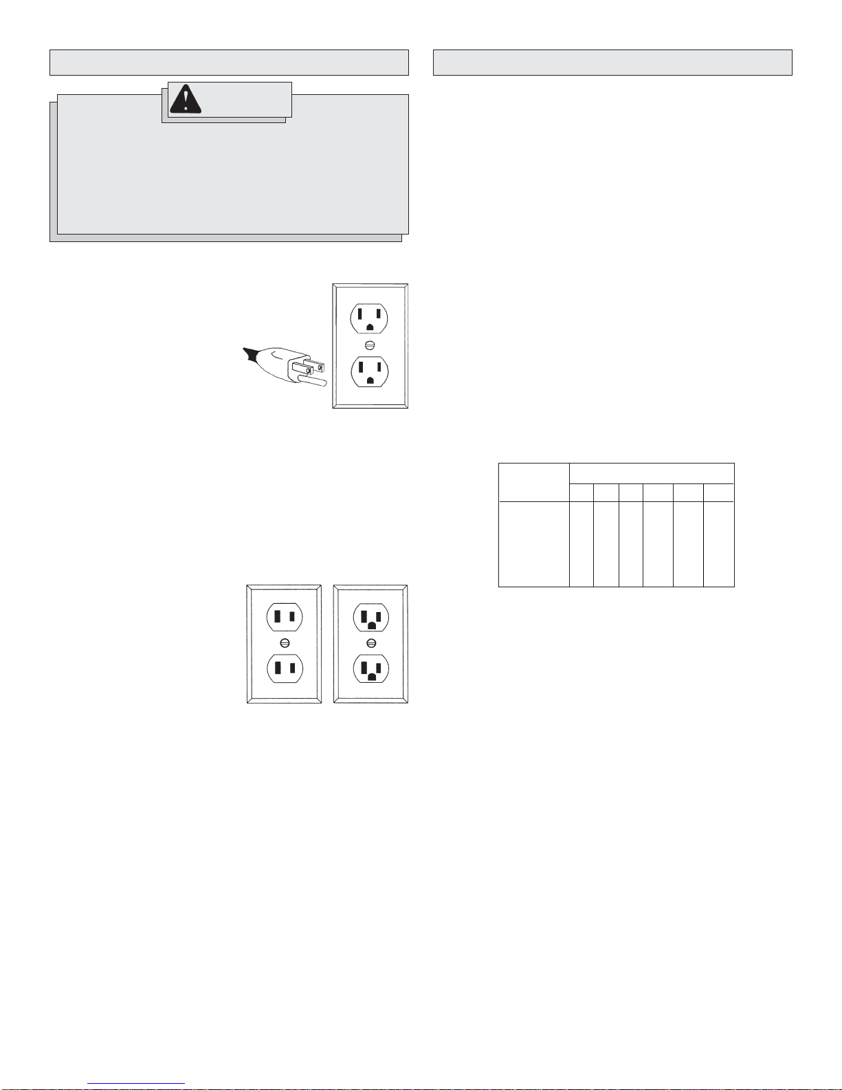
Grounded Tools:
Tools with Three Prong Plugs
Tools marked “Grounding Required”
have a three wire cord and three
prong grounding plug. The plug must
be connected to a properly grounded
outlet (See Figure A). If the tool should
electrically malfunction or break down,
grounding provides a low resistance
path to carry electricity away from
the user, reducing the risk of electric
shock.
The grounding prong in the plug is connected through the green wire inside
the cord to the grounding system in the tool. The green wire in the cord must
be the only wire connected to the tool's grounding system and must never
be attached to an electrically “live” terminal.
Y our tool must be plugged into an appropriate outlet, properly installed and
grounded in accordance with all codes and ordinances. The plug and outlet
should look like those in Figure A.
Double Insulated Tools:
Tools with Two Prong Plugs
Tools marked “Double Insulated” do
not require grounding. They have a
special double insulation system which
satisfies OSHA requirements and
complies with the applicable standards
of Underwriters Laboratories, Inc., the
Canadian Standard Association and
the National Electrical Code. Double
Insulated tools may be used in either
of the 120 volt outlets shown in Figures
B and C.
Fig. A
Fig. B
Fig. C
Guidelines for Using Extension Cords
• If you are using an extension cord outdoors, be sure it is marked with
the suffi x “W-A” (“W” in Canada) to indicate that it is acceptable for
outdoor use.
• Be sure your extension cord is properly wired and in good electrical
condition. Always replace a damaged extension cord or have it repaired
by a qualifi ed person before using it.
• Protect your extension cords from sharp objects, excessive heat and
damp or wet areas.
Recommended Minimum Wire Gauge
Nameplate
Amperes
5.1 - 8
8.1 - 12
12.1 - 15
15.1 - 20
* Based on limiting the line voltage drop to fi ve
volts at 150% of the rated amperes.
for Extension Cords*
25'
0 - 5
16
16
14
12
10
Extension Cord Length
100'
14
12
10
10
150'
12
10
--
--
--
--
50'
16
16
14
12
10
75'
16
14
12
10
10
200'
12
--
--
--
--
READ AND SAVE ALL INSTRUCTIONS
FOR FUTURE USE.
page 4
TOOL ASSEMBLY
WARNING
To reduce the risk of injury, always unplug
tool before attaching or removing accessories
or making adjustments. Use only specifically
recommended accessories. Others may be
hazardous.
Removing and Replacing Quik-Lok Cords (Fig. 1)
MILWAUKEE'S exclusive Quik-Lok Cords provide instant fi eld replace-
ment or substitution.
Fig. 1
1. T o remove the Quik-Lok Cord, turn the cord nut 1/4 turn to the left and
pull it out.
2. T o replace the Quik-Lok Cord, align the connector keyways and push
the connector in as far as it will go. Turn the cord nut 1/4 turn to the
right to lock.
WARNING
To reduce the risk of injury, always use a side
handle when using this tool. Always brace or hold
securely.
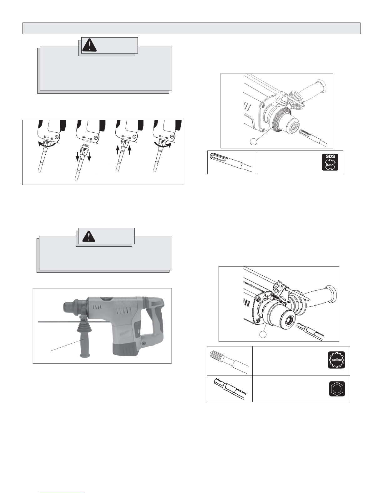
Installing Bits and Chisels (Fig. 3)
SDS Max Drive System (Cat. No. 5315-21)
The 5315-21 Rotary Hammer uses SDS max drill bits and hammer steel
chisels.
Fig. 3
1
Bit with SDS max shank
1. Insert the bit or chisel into the nose of the tool.
2. Rotate bit slowly until it aligns with the locking mechanism.
3. Push bit into tool until it locks.
4. Check to see that bit is locked by tugging on it.
5. To remove bits and chisels, pull bit release collar (1) toward the rear of
tool and remove bit.
NOTE: Use caution when handling hot bits and chisels.
Installing Bits and Chisels (Fig. 4)
Spline Drive System (Cat. No. 5319-21 & 5321-21)
The 5319-21 and 5321-21 Rotary Hammers use carbide bits with spline
shanks and hammer steel chisels with round hex shanks.
Fig. 4
Adjusting the Side Handle (Fig. 2)
Fig. 2
Side handle
1. Loosen the side handle slightly by unscrewing it counterclockwise.
2. Rotate the side handle to the required angle.
3. Tighten the side handle securely.
1
Rotary bit with spline shank
Chisel with round hex shank
1. Insert the bit or chisel into the nose of the tool.
If you are using a rotary bit, make sure that the splines on the shank
engage with the splines inside the nose of the tool.
If you are using a chisel, make sure that the notch in the shank faces up
(Fig. 4).
2. Push bit into tool until it locks.
3. Check to see that bit is locked by tugging on it.
4. To remove bits and chisels, pull bit release collar (1) toward the rear of
tool and remove bit.
NOTE: Use caution when handling hot bits and chisels.
page 5
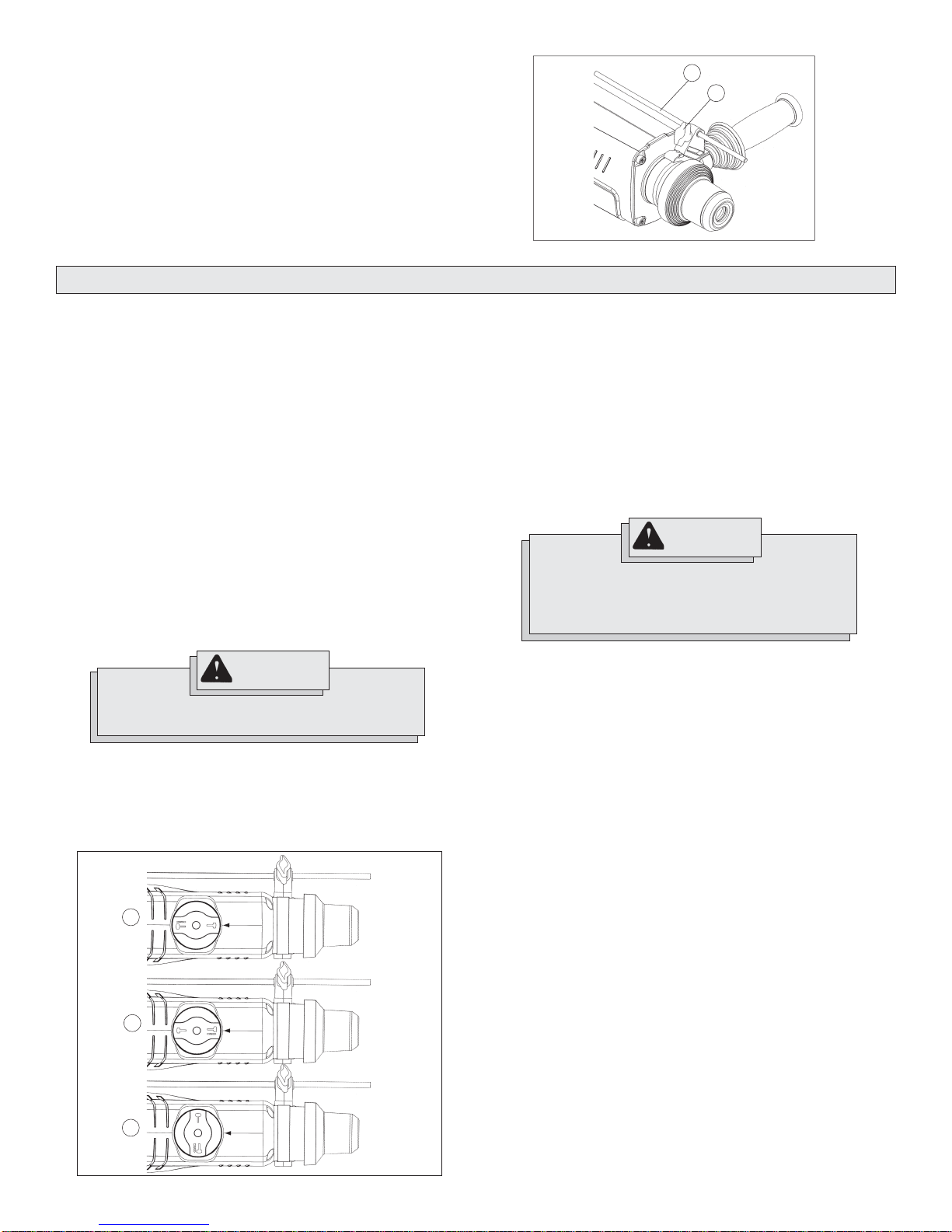
Setting the Depth Gauge (Fig. 5)
1. Loosen the depth gauge adjustment knob (2).
2. Slide the depth gauge rod (1) backward or forward until it is set for the
desired depth. The drilling depth is the distance between the tip of the
bit and the tip of the depth gauge rod.
3. Tighten the depth gauge adjustment knob securely.
OPERATION
Fig. 5
1
2
These rotary hammers have an Electronic Feedback Control Circuit (EFCC)
which helps improve the operation and life of the tool.
Soft Start
The Soft-Start feature reduces the amount of torque reaction to the tool and
the user. This feature gradually increases the motor speed up from zero to
the speed set by the speed control dial.
Feedback Control
The electronic speed control system allows the tool to maintain constant
speed between no-load and load conditions.
Service Indicator Light
These hammers feature a service indicator light. When the red service light
turns on, the tool is ready for servicing. Return the tool to an authorized
service center.
NOTE: When the service light is on, the tool will continue to run for a few
hours and then the motor will shut off.
Power Indicator Light
When the green power indicator light is on, current is entering the Elec-tronic
Feedback Control Circuit (EFCC) and the tool is ready for operation.
WARNING
To reduce the risk of injury, wear safety goggles or
glasses with side shields.
Selecting Action (Fig. 6)
(Cat. No. 5315-21 & 5321-21)
The 5315-21 and 5321-21 Rotary Hammers feature a stop rotation knob.
The stop rotation knob may be set for either “hammering-only” or “hammering-with-rotation”. The 5315-21 Rotary Hammer has a third setting that
allows the angle of the chisel blade to be adjusted.
Fig. 6
1
2
3
page 6
Cat. No.
5315-21
5315-22
5321-21
5321-22
Cat. No.
5315-21
5315-22
5321-21
5321-22
Cat. No.
5315-21
5315-22
only
1. Hammering only. For use with “hammering-only” accessories. Use
this setting (1) for chiseling or setting self-drilling anchors.
2. Hammering with rotation. Use this setting (2) for drilling holes with
drill bits.
3. Chisel adjustment. (Cat. No. 5315-21 only) Use this setting (3) to
adjust the angle of the chisel blade in relation to the tool. With a chisel
mounted in the tool:
• turn the knob to this setting
• twist the chisel to the desired angle
• set the tool for hammering only
NOTE: T o engage the hammering mechanism, maintain pressure on the bit.
When the pressure on the bit is released, the hammering will stop.
WARNING
To reduce the risk of injury, when using chisels or (other hammering-only accessories) in
the 5315-21 Rotary Hammer, set the tool in the
“hammering-only” position.
Hammering Only
SDS Max Drive System (Cat. No. 5315-21)
When using chisels (or other “hammering-only” accessories) in
the 5315-21 Rotary Hammer, the stop rotation knob MUST be set in
the“hammer-only” setting. The rotational drive mechanism in the
5315-21 engages with the chisel (or other “hammering-only” accessory) then it is mounted into the tool and the stop rotation knob is set for
“hammering-with-rotation”.
Hammering Only
Spline Drive System (Cat. No. 5319-21 & 5321-21)
When a chisel (or other “hammering-only” accessory) is mounted into the
5319-21 or 5321-21 Rotary Hammer, the rotational drive mechanism does
not engage with the chisel. The 5321-21 can use chisels in the “hammering-with-rotation” setting or the “hammering-only” setting.
NOTE: The 5321-21 Rotary Hammer must be set in the “hammeringonly” setting when setting self-drilling anchors. See “Setting Self-Drilling
Anchors" for complete instructions.
Selecting Speed
These rotary hammers have a speed control dial. The speed control dial
allows the user to adjust the rotating speed (RPM) and the impact rate
(BPM) of the tool.
To change the speed, set the speed control dial to the desired setting.
Lower speeds provide more control when starting holes and reduce ‘spalling’
on breakthrough. Spalling occurs when pieces of material chip off around the
drilled hole on breakthrough. When chiseling in soft or brittle materials, use
lower speeds to reduce damage to surrounding areas of the material.
Higher speeds provide for faster penetration when drilling and chiseling in
demolition work.
Starting and Stopping the Tool
1. To start the tool, pull trigger.
2. To stop the tool, release trigger.
Cold Starting
If this tool is stored for a long period of time or at cold temperatures,
it may not hammer initially because the lubrication has become stiff.
To warm up the tool:
1. Insert and lock a bit or chisel into the tool.
2. Turn the tool on, applying force to the bit or chisel against a concrete
or wood surface.
3. Turn the tool on and off every few seconds. In a short time, the tool will
start hammering. The colder the tool is, the longer it will take to warm
it up.
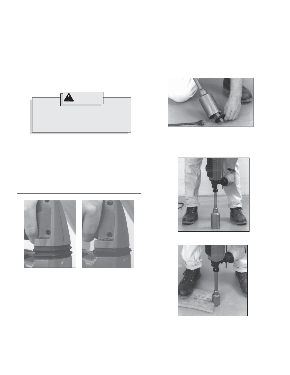
WARNING
Applying greater pressure does not increase the
tool's effectiveness. If the applied working pressure is too high, the shock absorber will be pushed
together making the vibrations to the handle noticeably stronger.
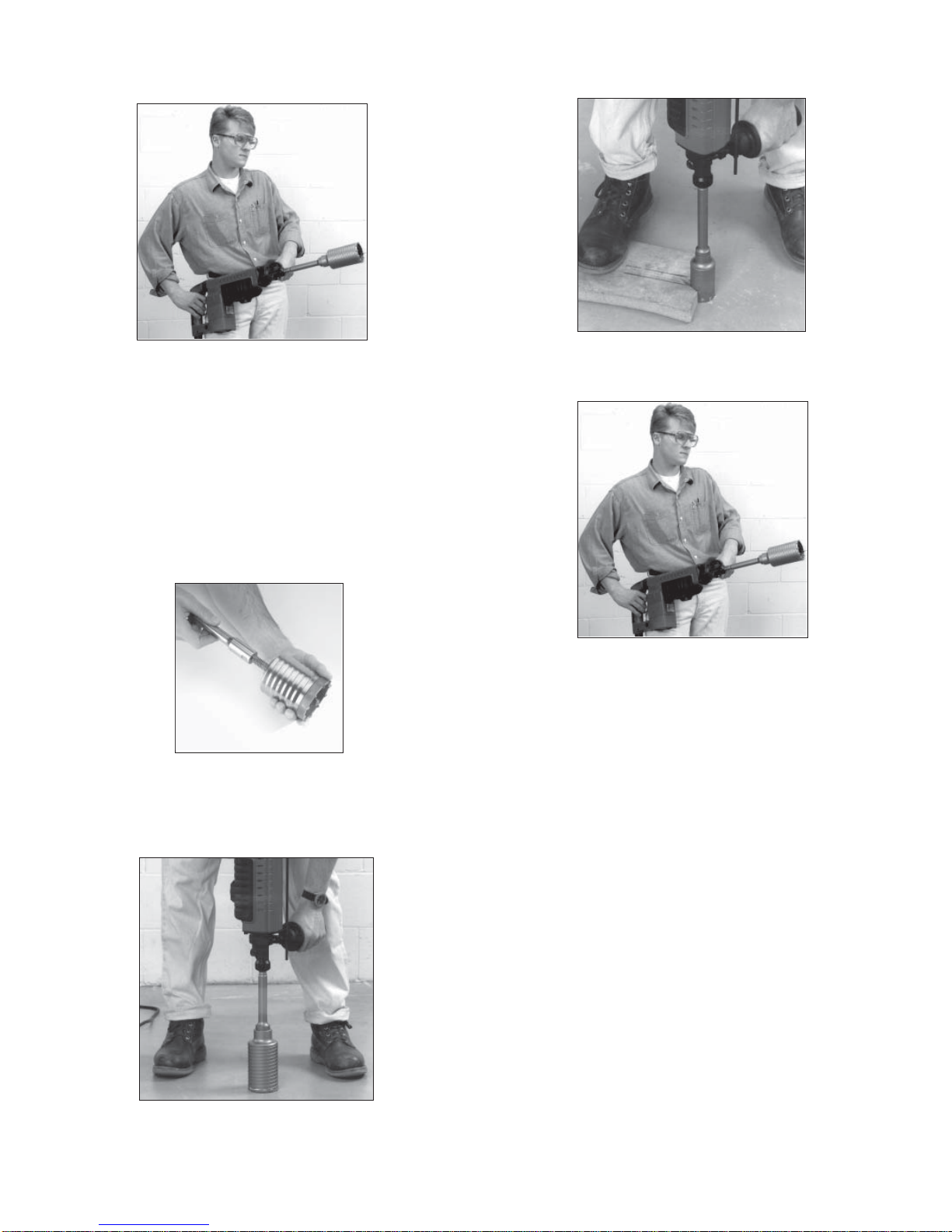
Operator Force (Fig. 7)
These rotary hammers feature the Vibration Isolation System to provide the operator with comfort without sacrificing power or performance. The motor is suspended independently from the switch handle.
Insulating elements absorb up to 50% of the vibration when hammering
and drilling.
Ideal operator force compresses the bellows slightly and allows the tool to
work aggressively while the handle remains steady.
Excessive force compresses the bellows signifi cantly and reduces vibration
dampening. Users will be able to feel the difference and should adjust the
force to the handle accordingly (Fig. 7).
Fig. 7
Using Rotary Percussion Core Bits (Fig. 8-11)
Core bits are useful for drilling large holes for conduit and pipe.
MILWAUKEE Heavy-Duty Core Bits have heat-treated steel bodies with
durable carbide tips. These core bits are specially designed for fast, accurate
drilling with combined hammering and rotary action.
1. Clean and lubricate the threads on the adapter and core bit to make
later removal easier. Screw the threaded end of the adapter into the
rear of the core bit.
2. Push the guide plate onto the pointed end of the center pin. Insert the
center pin and guide plate assembly into the core bit. Be sure the small
end of the center pin is securely placed into the hole in the center of
the core bit (Fig. 8).
Fig. 8
3. Insert the adapter into the nose of the tool as described in “Installing Bits”. Set the stop rotation knob to the hammering-with-rotation
setting.
4. Press the center pin fi rmly against your center mark, hold the tool fi rmly
and pull the trigger (Fig. 9).
Fig. 9
ideal applied force
The side handle works in a similar fashion, where moderate operator force
dampens vibration and excessive force reduces this effect.
Hammering or Hammering with Rotation
Position the tool, grasp the handles fi rmly and pull the trigger.
Always hold the tool securely using both handles and maintain control. Use
only enough pressure to hold the tool in place and prevent the tip of the bit
from wandering. This tool has been designed to achieve top performance
with only moderate pressure. Let the tool do the work.
When drilling deep holes occasionally pull the bit partially out of the hole
while the tool is running to help clear dust.
NOTE: Do not use water to settle the dust since it will clog the bit fl utes
and tend to make the bit bind in the hole. If the bit should bind, a built-in,
non-adjustable slip clutch prevents the bit from turning. If this occurs, stop
the tool, free the bit and begin again.
excessive applied force
NOTE: If a center pin and guide plate are not available, use a template
or notched board to start the hole (Fig. 10).
Fig. 10
5. After drilling to about the depth of the core bit teeth, remove the center
pin and guide plate from the core bit. Resume drilling.
page 7
6. To change the core bit, hold the tool upwards, pointing it away from
your body as shown, and run it briefl y in forward to loosen the core bit
from the adapter (Fig. 11).
Fig. 11
NOTE: If the 48-20-5099 threaded stud is used, use a template or
notched board to start the hole (Fig. 14).
Fig. 14
NOTE: To make deeper holes, remove the core bit, break and remove
the core. Resume drilling.
Using LHS Rotary Percussion Core Bits (Fig. 12-15)
LHS Core Bits are useful for drilling large or long holes in concrete.
MILWAUKEE Heavy-Duty Core Bits have heat-treated steel bodies with
durable carbide tips. These core bits are specially designed for fast, accurate
drilling with combined hammering and rotary action.
1. Clean and lubricate the threads on the adapter and core bit to make
later removal easier. Screw the threaded end of the centering bit into
the core bit (Fig. 12). Thread the adapter shank to the rear of the core
bit.
NOTE: If using an extension, fi rst thread the adapter shank to the
extension. Then thread the core bit to the extension.
Fig. 12
2. Insert the adapter into the nose of the tool as described in “Installing Bits”. Set the stop rotation knob to the hammering-with-rotation
setting.
3. Press the centering bit fi rmly against your center mark, hold the tool
fi rmly and pull the trigger (Fig. 13).
4. To change the core bit, hold the tool upwards, pointing it away from
your body as shown, and run it briefl y in forward to loosen the core bit
from the adapter (Fig. 15).
Fig. 15
NOTE: To make deeper holes, remove the core bit, break and remove the
core. Resume drilling. When drilling long or deep holes, after each inch of
penetration pull the bit partially out of the hole while the tool is running,
to help clear dust from the bit fl utes. Dust can clog the bit fl utes and can
make the bit bind in the hole. If this occurs, stop the tool, free the bit and
begin again.
Fig. 13
page 8
WARNING
To reduce the risk of personal injury and
damage to the tool or work:
• Always use the “hammering-only” setting to
set the anchor. Never use the “hammering-withrotation” setting to set the anchor.
• Never switch the tool to “hammering-with-rotation” until after the anchor has been set and the
tooth anchor chuck has been removed from the
anchor.
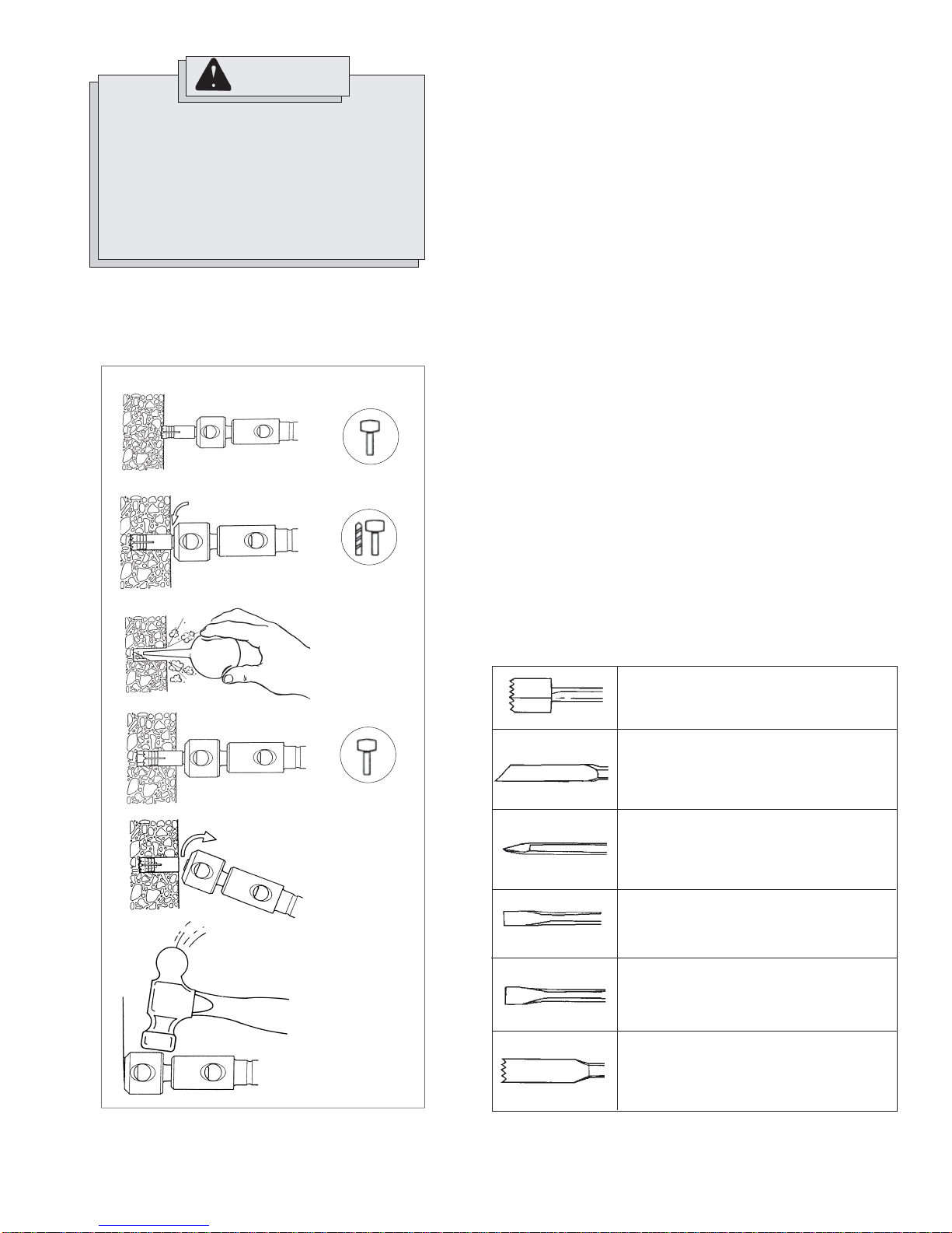
Setting Self-Drilling Anchors (Fig. 16-21)
(Cat. No. 5315-21 & 5321-21 only)
The 5315-21 and 5321-21 Rotary Hammers feature a stop rotation knob
which is helpful for setting self-drilling anchors up to 5/8". MILWAUKEE
Tooth Anchor Chucks require a “B” taper adapter.
Fig. 16
Fig. 17
1/8"
Fig. 18
1. Place the proper size tooth anchor chuck into the “B” taper adapter.
Then insert the “B” taper adapter into the tool and lock it into place as
described. See “Installing Bits and Chisels”.
2. Insert the anchor into the tooth anchor chuck. Set the stop rotation knob
for hammering only. Set the anchor on your mark and hammer until the
teeth have penetrated the concrete (Fig. 16).
3. Set the stop rotation knob for hammering with rotation and drill until the
chuck is 1/8" above the concrete (Fig. 17).
NOTE: It may be necessary to clean dust and cuttings from the anchor
several times while drilling the hole.
4. Remove the anchor from the hole while the tool is running. Clean the
dust and cuttings from the anchor by pointing it downward and turning
the tool on and off several times. Clean the dust out of the hole with a
vacuum cleaner or blowout bulb (Fig. 18).
5. Place the expansion plug into the anchor and insert the anchor into
the hole. Switch the stop rotation knob back to hammering only, and
hammer the anchor fi rmly into the hole (Fig. 19).
6. Snap the head off of the anchor. To remove the head of anchors up
to 5/8", grasp the handles fi rmly and pull the tool sharply towards you
(Fig. 20) or snap off the anchor head with a hand hammer as shown
(Fig. 21). The anchor is now ready to receive a bolt.
7. To remove the anchor head wedged in the tooth anchor chuck, use drift
pin 48-86-0100.
8. To remove the tooth anchor chuck, remove the “B” taper adapter from
the nose of the tool. Insert the drift pin supplied with the adapter into the
hole on the side of the “B” taper adapter and strike it sharply to force
out the tooth anchor chuck.
Chiseling and Chipping
MILWAUKEE 1-1/2" Rotary Hammers may be used for chipping and chiseling.
When chiseling, hold the tool at an angle to the workpiece. Work from a
corner or close to the edge of the workpiece, breaking off one small area at
a time rather than attempting too large an area.
A variety of accessories are available.
Fig. 19
Fig. 20
Fig. 21
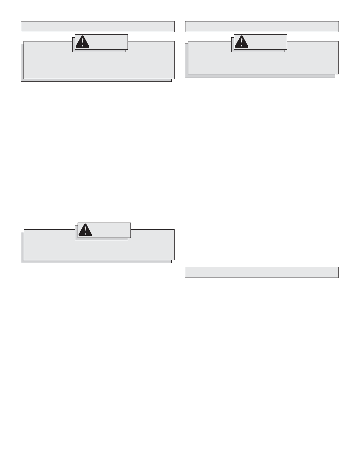
Bushing Tools
Used to surface concrete.
Mortar Cutting Chisels (Seam Tools)
For removing old mortar for tuck pointing or
caulking.
Bull Points
For demolition work and starting holes in
concrete slabs.
Flat Chisels
For edging, chipping or channeling.
Scaling Chisels
For removing weld spatter or scale and cutting straight lines.
Slotting Chisel
For slotting and cutting between drilled holes
in concrete and masonry.
page 9
MAINTENANCE
ACCESSORIES
WARNING
To reduce the risk of injury, always unplug your tool before performing any maintenance. Never disassemble the tool or try to do
any rewiring on the tool's electrical system. Contact a MILW AUKEE
service facility for ALL repairs.
Maintaining Tools
Keep your tool in good repair by adopting a regular maintenance program. Before use, examine the general condition of your tool. Inspect
guards, switches, tool cord set and extension cord for damage. Check
for loose screws, misalignment, binding of moving parts, improper
mounting, broken parts and any other condition that may affect its safe
operation. If abnormal noise or vibration occurs, turn the tool off immediately and have the problem corrected before further use. Do not
use a damaged tool. Tag damaged tools “DO NOT USE” until repaired
(see “Repairs”).
Under normal conditions, relubrication is not necessary until the motor
brushes need to be replaced. After six months to one year, depending on
use, return your tool to the nearest MILWAUKEE service facility for the
following:
• Lubrication
• Brush inspection and replacement
• Mechanical inspection and cleaning (gears, spindles, bearings,
housing, etc.)
• Electrical inspection (switch, cord, armature, etc.)
• Testing to assure proper mechanical and electrical operation
WARNING
To reduce the risk of injury, always unplug the tool before attaching or removing accessories. Use only specifi cally recommended
accessories. Others may be hazardous.
For a complete listing of accessories refer to your MILWAUKEE Electric Tool catalog or go on-line to www.milwaukeetool.com. To obtain a
catalog, contact your local distributor or a service center.
WARNING
To reduce the risk of injury, electric shock and damage to the tool,
never immerse your tool in liquid or allow a liquid to fl ow inside
the tool.
Cleaning
Clean dust and debris from vents. Keep the tool handles clean, dry and
free of oil or grease. Use only mild soap and a damp cloth to clean your
tool since certain cleaning agents and solvents are harmful to plastics and
other insulated parts. Some of these include: gasoline, turpentine, lacquer
thinner, paint thinner, chlorinated cleaning solvents, ammonia and household detergents containing ammonia. Never use fl ammable or combustible
solvents around tools.
Repairs
If your tool is damaged, return the entire tool to the nearest service center.
page 10
FIVE YEAR TOOL LIMITED WARRANTY
Every MILWAUKEE tool is tested before leaving the factory and is warranted to be free from defects in material and workmanship. MILWAUKEE
will repair or replace (at MILWAUKEE’s discretion), without charge, any
tool (including battery chargers) which examination proves to be defective
in material or workmanship from fi ve (5) years after the date of purchase.
Return the tool and a copy of the purchase receipt or other proof of purchase to a MILW AUKEE Factory Service/Sales Support Branch location or
MILWAUKEE Authorized Service Station, freight prepaid and insured. This
warranty does not cover damage from repairs made or attempted by other
than MILW AUKEE authorized personnel, abuse, normal wear and tear , lack
of maintenance, or accidents.
The warranty period for V28 Battery Packs is two (2) years from the date of
purchase. The warranty period for Ni-Cd battery Packs, Flashlights, Radios
are warranted for one (1) year from the date of purchase.
THE REPAIR AND REPLACEMENT REMEDIES DESCRIBED HEREIN ARE
EXCLUSIVE. IN NO EVENT SHALL MILWAUKEE BE LIABLE FOR ANY
INCIDENTAL, SPECIAL, OR CONSEQUENTIAL DAMAGES, INCLUDING
LOSS OF PROFITS.
THIS WARRANTY IS EXCLUSIVE AND IN LIEU OF ALL OTHER WARRANTIES, OR CONDITIONS, WRITTEN OR ORAL, EXPRESSED OR
IMPLIED FOR MERCHANTABLILITY OR FITNESS FOR PARTICULAR
USE OR PURPOSE.
This warranty gives you specifi c legal rights. You may also have other rights
that vary from state to state and province to province. In those states that
do not allow the exclusion of implied warranties or limitation of incidental
or consequential damages, the above limitations or exclusions may not
apply to you. This warranty applies to the United States, Canada, and
Mexico only.
 Loading...