

OPERATOR'S MANUAL
MANUEL de L'UTILISATEUR
MANUAL del OPERADOR
Cat. No. / No de cat.
3510-20
®
REDLITHIUM
LASER A POINTS USB REDLITHIUM
LÁSER DE PUNTO RECARGABLE MEDIANTE USB
REDLITHIUM
WARNING To reduce the risk of injury, user must read and understand operator's manual.
AVERTISSEMENT An de réduire le risque de blessures, l'utilisateur doit lire et bien
comprendre le manuel.
ADVERTENCIA Para reducir el riesgo de lesiones, el usuario debe leer y entender el manual.
USB POINT LASER
®
®

GENERAL POWER
WARNING
WARNING
TOOL SAFETY
WARNINGS
Read and understand all instruc-
listed below, may result in electric shock, re and/or
serious personal injury. Save all warnings and instructions for future reference.
• Save these instructions - This operator's manual
contains important safety and operating instructions.
tions. Failure to follow all instructions
LASER SAFETY
The device produces visible laser
tool.
• This device complies with 21 CFR 1040.10 and
1040.11 except for conformance with IEC 60825-1
Ed. 3., as described in Laser Notice No. 56, dated
May 8, 2019.
•Laser light - Do not stare into beam or view directly with optical instruments. Do not point laser
light at others. Laser light can cause eye damage.
beams, which are emitted from the
WORK AREA SAFETY
• Ensure adequate safeguards at the work site
(e.g. surveying site when measuring on roads,
construction sites, etc.).
• Avoid dangerous environments. Avoid extended
exposure to rain, snow, damp or wet locations. Do
not use in the presence of explosive atmospheres
(gaseous fumes, dust or ammable materials).
PERSONAL SAFETY
• Do not allow persons unfamiliar with the tool,
these safety instructions, and the tool's operator's manual to operate the tool. This tool can be
dangerous in the hands of untrained users.
• Do not overreach. Keep proper footing and
balance at all times. This enables better control
of the tool in unexpected situations.
BATTERY USE
AND CARE
• USE AND CHARGE ONLY REDLITHIUM® USB
BATTERIES IN THIS USB RECHARGEABLE
TOOL. OTHER TYPES OF BATTERIES MAY
CAUSE PERSONAL INJURY AND DAMAGE.
• BEFORE USING THE BATTERY AND TOOL,
READ THIS OPERATOR’S MANUAL AND ALL
LABELS ON THE BATTERY AND TOOL.
• USE ONLY WITH LISTED/CERTIFIED ITE
POWER SUPPLY. Others may result in a risk of re,
electric shock or personal injury.
• CHARGE IN A WELL VENTILATED AREA. Do not
block charger vents. Keep them clear to allow proper
ventilation. Do not allow smoking or open ames
near a charging battery. Vented gases may explode.
• MAINTAIN CORD. When unplugging charger, pull
plug rather than cord to reduce the risk of damage to
the electrical plug and cord. Never carry charger by
its cord. Keep cord from heat, oil and sharp edges.
Make sure cord will not be stepped on, tripped over
or subjected to damage or stress. Do not use charger
with damaged cord or plug. Have a damaged charger
replaced immediately.
• USE ONLY RECOMMENDED ATTACHMENTS. Use
of an attachment not recommended or sold by the
battery charger or battery manufacturer may result in
a risk of re, electric shock or personal injury.
• TO REDUCE THE RISK OF ELECTRIC SHOCK, al-
ways unplug charger before cleaning or maintenance.
• DO NOT BURN OR INCINERATE BATTERY
PACKS. Battery may explode, causing personal
injury or damage. Toxic fumes and materials are
created when batteries are burned.
• DO NOT CRUSH, DROP, OR DAMAGE battery. Do
not use a battery or charger that has received a sharp
blow, been dropped, run over, or damaged in any way
(e.g., pierced with a nail, hit with a hammer, stepped on).
• DO NOT DISASSEMBLE. Incorrect reassembly
may result in the risk of electric shock, re or exposure to battery chemicals. If it is damaged, take it to
a MILWAUKEE service facility.
• BATTERY CHEMICALS CAUSE SERIOUS BURNS.
Never allow contact with skin, eyes, or mouth. If
a damaged battery leaks battery chemicals, use
rubber or neoprene gloves to dispose of it. If skin is
exposed to battery uids, wash with soap and water
and rinse with vinegar. If eyes are exposed to bat-
tery chemicals, immediately ush with water for 20
minutes and seek medical attention. Remove and
dispose of contaminated clothing.
• DO NOT SHORT CIRCUIT. A battery pack will short
circuit if a metal object makes a connection between
the positive and negative contacts on the battery
pack. Do not place a battery pack near anything that
may cause a short circuit, such as coins, keys or
nails in your pocket. Do not allow uids to ow into
battery pack. Corrosive or conductive uids, such as
seawater, certain industrial chemicals, and bleach or
bleach containing products, etc., can cause a short
circuit. A short circuited battery pack may cause re,
personal injury, and product damage.
• STORE YOUR BATTERY AND TOOL in a cool, dry
place. Do not store battery where temperatures may
exceed 120°F (50°C) such as in direct sunlight, a
vehicle or metal building during the summer.
SPECIFIC SAFETY
RULES FOR
LASER LEVELS
•Watch out for erroneous results if the tool is
defective or if it has been dropped, misused or
modied.
•Do not dispose of tool or batteries together with
household waste material! Tool and batteries that
have reached the end of their life must be collected
separately and returned to an environmentally
compatible recycling facility.
•Ensure tool magnets are securely mounted to
a metal surface. Magnet strength may not hold
on thin metal surfaces, causing the tool to fall.
• Always use common sense and be cautious when
using tools. It is not possible to anticipate every
situation that could result in a dangerous outcome.
Do not use this tool if you do not understand these
operating instructions or you feel the work is beyond
your capability; contact Milwaukee Tool or a trained
professional for additional information or training.
• Maintain labels and nameplates. These carry
important information. If unreadable or missing,
contact MILWAUKEE for a free replacement.
2

• The device conforms to the most stringent
WARNING
requirements of the relevant Electromagnetic
Compatibility (EMC) Standards and Regulations.
Yet, the possibility of causing interference in other
devices cannot be totally excluded.
CAUTION
than those specied herein may result in hazardous radiation exposure.
• Be sure to power o instrument after use. When
instrument will not be used for a long period, place
it in storage after removing batteries.
proved by the party responsible for compliance could
void the user’s authority to operate the equipment.
This equipment has been tested and found to comply
with the limits for a Class B digital device, pursuant to
Part 15 of the FCC Rules. These limits are designed
to provide reasonable protection against harmful interference in a residential installation. This equipment
generates, uses and can radiate radio frequency
energy and, if not installed and used in accordance
with the instructions, may cause harmful interference
to radio communications.
However, there is no guarantee that interference will
not occur in a particular installation. If this equipment
does cause harmful interference to radio or television reception, which can be determined by turning
the equipment o and on, the user is encouraged to
try to correct the interference by one or more of the
following measures:
• Reorient or relocate the receiving antenna.
• Increase the separation between the equipment and
receiver.
• Consult the dealer or an experienced radio/TV
technician for help.
Use of controls or adjustments or
performance of procedures other
Federal Communications Commission
Changes or modications to
this unit not expressly ap-
SPECIFICATIONS
Cat. No ...................................................... 3510-20
USB Input Volts .............................................. 5 DC
USB Input Amps ..................................... 0.1 - 2.1 A
Output Volts .................................................... 4 DC
Output Amps ....................................................2.1 A
REDLITHIUM
Volts ................................................................ 4 DC
Power Supply Cat. No. ....................... 48-59-1202
Laser............................................................Class 2
Points Max Power............................... P
Wavelength.......................................... 510-530 nm
Points Beam Divergence .......................... 0.5 mrad
Storage Temp .................................... -4°F to 120°F
Working Range .................................................150'
Accuracy ............................................... ±1/8" @ 33'
Settle Time ......................................... < 3 Seconds
Tripod Mount ...............................................1/4"-20
Ingress Protection............................................ IP54
Drop Rating .......................................................1 m
Leveling ............Auto ±°4 side to side, front to back
Operating Temperature
Battery and Charger ........................ 40°F to 104°F
Battery and Tool ............................... 14°F to 104°F
®
USB Batteries
≤ 1 mW
AVG
FUNCTIONAL
DESCRIPTION
1. Laser apertures
2. Battery compartment
3. On/O dial
4. Adjustable clearance
bracket
1
1
1
8
2
5
7
5. Fuel gauges
6. USB power outlet
7. Threaded insert
8. Magnets
3
4
5
6
SYMBOLOGY
Volts
CLASS 2 LASER PRODUCT
Universal Serial Bus (USB)
Magnets
Read operator’s manual
Direct Current
Amps
LASER RADIATION
DO NOT STARE INTO BEAM
Batteries
3
Properly Recycle

WARNING
WARNING
CAUTION
NOTICE
BATTERY
WARNING
WARNING
WARNING
To reduce the risk of re, personal
a short circuit, never immerse your tool, battery
pack or charger in uid or allow a uid to ow
inside them. Corrosive or conductive uids, such
as seawater, certain industrial chemicals, and
bleach or bleach containing products, etc., can
cause a short circuit.
Do not expose your battery or cordless tools to water or
rain, or allow them to get wet. This could damage the
tool and battery. Do not use oil or solvents to clean or
lubricate your battery. The plastic casing will become
brittle and crack, causing a risk of injury.
Store batteries at room temperature away from mois
ture. Do not store in damp locations where corrosion
of terminals may occur. As with other battery types,
permanent capacity loss can result if the pack is stored
for long periods of time at high temperatures (over 120°
F). MILWAUKEE Li-Ion batteries maintain their charge
during storage longer than other battery types. After
about a year of storage, charge the battery as normal.
battery pack even if it is damaged, dead or completely discharged. When burned, toxic fumes
and materials are created.
Disposing of MILWAUKEE Li-Ion Battery
MILWAUKEE Li-Ion batteries are more environmentally friendly than some other types of power tool
batteries. Always dispose of your battery according
to federal, state and local regulations. Contact a
recycling agency in your area for recycling locations.
Even discharged batteries contain some energy.
Before disposing, use electrical tape to cover the
terminals to prevent the battery from shorting, which
could cause a re or explosion.
The RBRC™ Battery Recycling Seals (see "Symbology") on your batteries indicate that MILWAUKEE
has arranged for the recycling of that battery with
the Rechargeable Battery Recycling Corporation
(RBRC). At the end of your battery's useful life,
return the battery to a MILWAUKEE Branch Oce/
Service Center or the participating retailer nearest
you. For more information, visit the RBRC web site
at www.rbrc.org.
injury, and product damage due to
Maintenance and Storage
To reduce the risk of injury or ex-
plosion, never burn or incinerate a
RBRC Battery Recycling Seals
ASSEMBLY
Use and charge only REDLITHIUM®
chargeable tool. Other types of batteries may
cause personal injury and damage.
1. Twist the battery cap and remove.
2. Line up the arrow on the battery with the arrow in
the compartment and fully insert the battery.
3. Replace the cap and twist to secure.
When the tool is turned on under battery power only, the
remaining battery life is displayed
Green Solid: 50-100% remaining
Yellow Solid: 11-49% remaining
Red Solid: 3-10% remaining
USB batteries in this USB re-
Inserting the Battery
Charging the Battery
:
To indicate low battery level, the laser beams will
blink quickly 3 times, followed by 4 seconds of solid
on (repeating). Charge the battery.
To charge the battery with laser powered o:
1. Plug your USB cable into a power source such as
an AC wall adaptor, computer, or car port.
2. Lift the rubber cover to expose the micro USB port.
Insert the micro USB plug into the micro USB port.
Users may experience longer charge times from
laptops and other power sources.
3. The indicator light will display the charging status:
Pulsing Red: Charging, 0-49% charged
Pulsing Yellow: Charging, 50-99% charged
Solid Green: 100% Charged.
To charge the battery with laser in use, follow
steps1-2 listed in the section above. The indicator
light will display the charging status:
-
Pulsing Red (Continuous)
Upon removal of USB cable, fuel gauge will display current battery life.
Flashing Red/Green: USB cable inserted without
battery installed & Damaged or Faulty Battery. If
the light indicator ashes red and green, check
that the battery is fully seated into the bay. Remove the battery and reinsert. If the light contin-
ues to ash red and green, the battery may be
extremely hot or cold, or wet. Allow the battery to
cool down, warm up, or dry out and then reinsert.
If the problem persists, contact a MILWAUKEE
service facility.
NOTE: When the laser level is charged during
USE, the indicator light will be Pulsing Red (Con-
tinuous). When the USB cable is disconnected,
the fuel gauge will display current battery life.
laser before starting an operation. Injury/damage
may occur if the laser falls.
Mounting/Adjusting the Laser Level
The adjustable clearance bracket can be used to
mount the laser level in multiple ways:
• Use the embedded magnets to secure the laser level
to framing steel studs, steel beams, etc.
• Use the keyhole slot to hang the laser level on the
wall with a nail or screw.
• Set the laser level on a at surface.
• Position the laser and/or wall mount on a stable
surface.
• Use the ¼" - 20 threaded insert to mount on a tripod.
Hold the bracket and adjust the laser up or down until
the desired clearance is achieved.
To reduce the risk of injury or damage, securely mount/attach the
Adjustable Clearance Bracket
OPERATION
To reduce the risk of injury or tem-
look directly into the laser when it is on.
than those specied herein may result in hazardous radiation exposure.
of each new Laser Level and before exposure to
jobsite conditions. See "Accuracy Field Check"
for information.
4
porary eects on vision, do not
Use of controls or adjustments or
performance of procedures other
Perform the Accuracy Field Check
procedure immediately upon unboxing
To turn on the laser and unlock the pendulum, rotate
NOTICE
66'
1'
the On/O dial to the desired position. The remaining
battery life will be displayed. WARNING! Do not look
directly into laser apertures.
ON Turns ON the laser and unlocks the pendu-
OFF Turns OFF the laser and locks the pen-
1. For best results, place the tool on a work surface
that is:
• sturdy
• level (within 4 degrees of true level)
• free of vibrations
• 90° to the work area
2. Turn on the tool.
3. The tool will self-level when placed on surfaces
within 4 degrees of true level.
4. The tool is ready once the emitted points are continuous and no longer moving on the work surface.
5. If the tool cannot achieve a level state (i.e., the
work surface is > 4 degrees o true level), the laser
points will ash rapidly (3 ashes per second).
Relocate or adjust the work surface.
If the tool does not turn on:
• Ensure battery is installed properly. Fuel gauge
should indicate remaining charge when correctly
installed.
• Ensure battery is charged.
• Ensure the tool's internal temperature is within
specied operating ranges. If stored in excessive
heat or cold, allow at least 2 hours to acclimate to
ambient temperature before turning on the tool.
If problem persists, please contact a MILWAUKEE
service facility for support.
Turning On/O
lum to enable self-leveling.
dulum. When not in use, turn o the tool
and store the Laser Level in the protective
carrying case.
Using the Laser Level
Troubleshooting
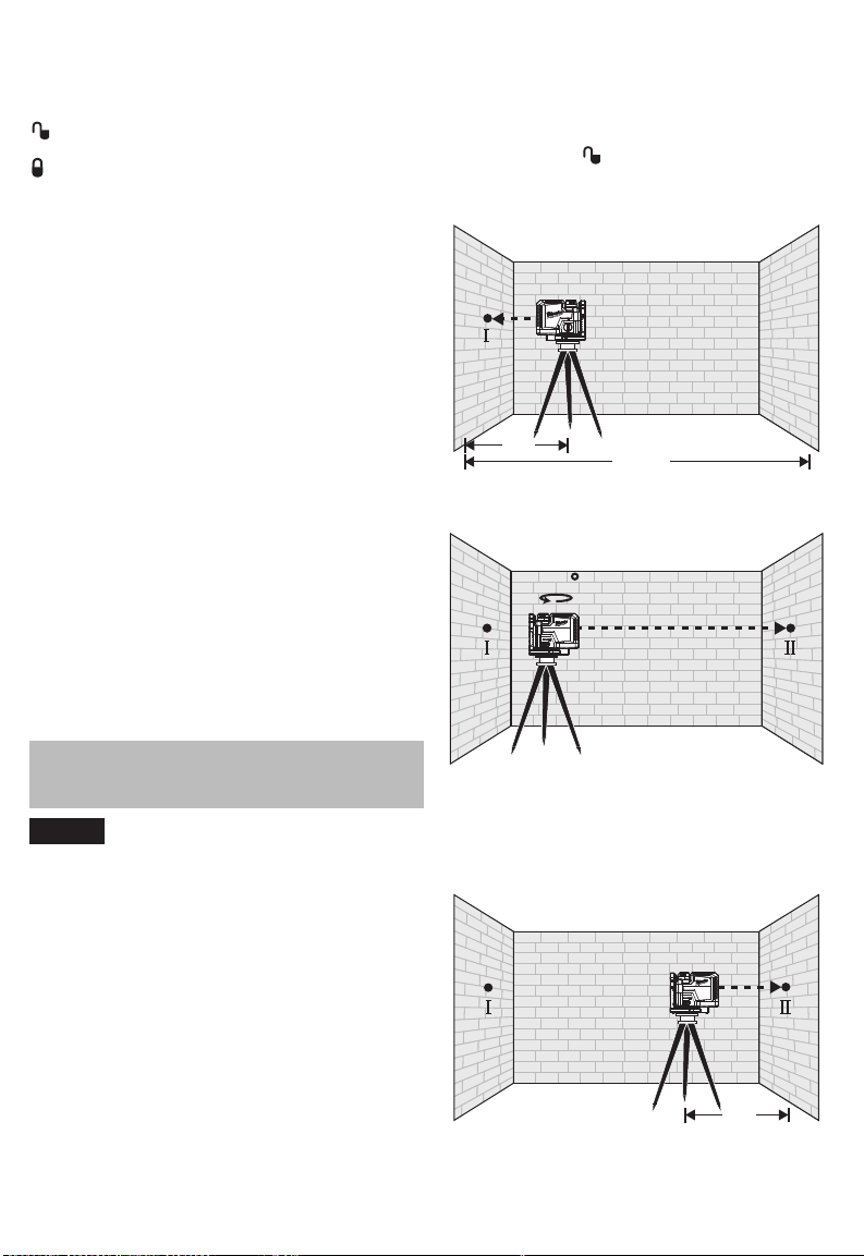
Horizontal Leveling Accuracy
A free measuring distance of approximately 66' on a
rm surface between two walls or structures A and
B is required for this check.
It is also suggested to mount the Laser Level to a
commercially available Tripod for easy adjustment.
1. Securely mount the tool within 1' of wall A.
2. Turn the tool to
3. Direct the front laser beam against the nearest
wall A and allow to self-level. Mark the center of
the laser point on the wall (point I).
ON.
A B
1'
4. Rotate the tool 180° without changing the height,
allow it to self-level, and mark the center point of
the laser point on the opposite wall B (point II).
A B
180
ACCURACY FIELD
CHECK
Perform the Accuracy Field Check
of each new Laser Level and before exposure to
jobsite conditions. See "Accuracy Field Check"
for information. Should any deviation from listed
product accuracy be found, please contact a MILWAUKEE service facility. Failure to do
so could result in rejection of warranty claim.
Ambient temperature gradients can impact laser
accuracy. For accurate and repeatable results, the
following procedure should be conducted with the
laser elevated o the ground and placed in the center
of the working area.
Abusive treatment of the Laser Level, such as excessive impacts from drop, can also lead to deviations
in product accuracy.
Therefore, it is recommended to conduct the Field
Check procedure after any impact or before completing any critical jobs.
procedure immediately upon unboxing
Inuences on Accuracy
5. Move the tool within 1' of wall B. Turn on the tool
and align the front laser point in the general direction of point II on wall B.
6. Adjust the height of the tool (using the tripod or by
adding shims, if required) to align the center point
of the laser beam directly onto point II on wall B.
Allow the tool to self-level.
A B
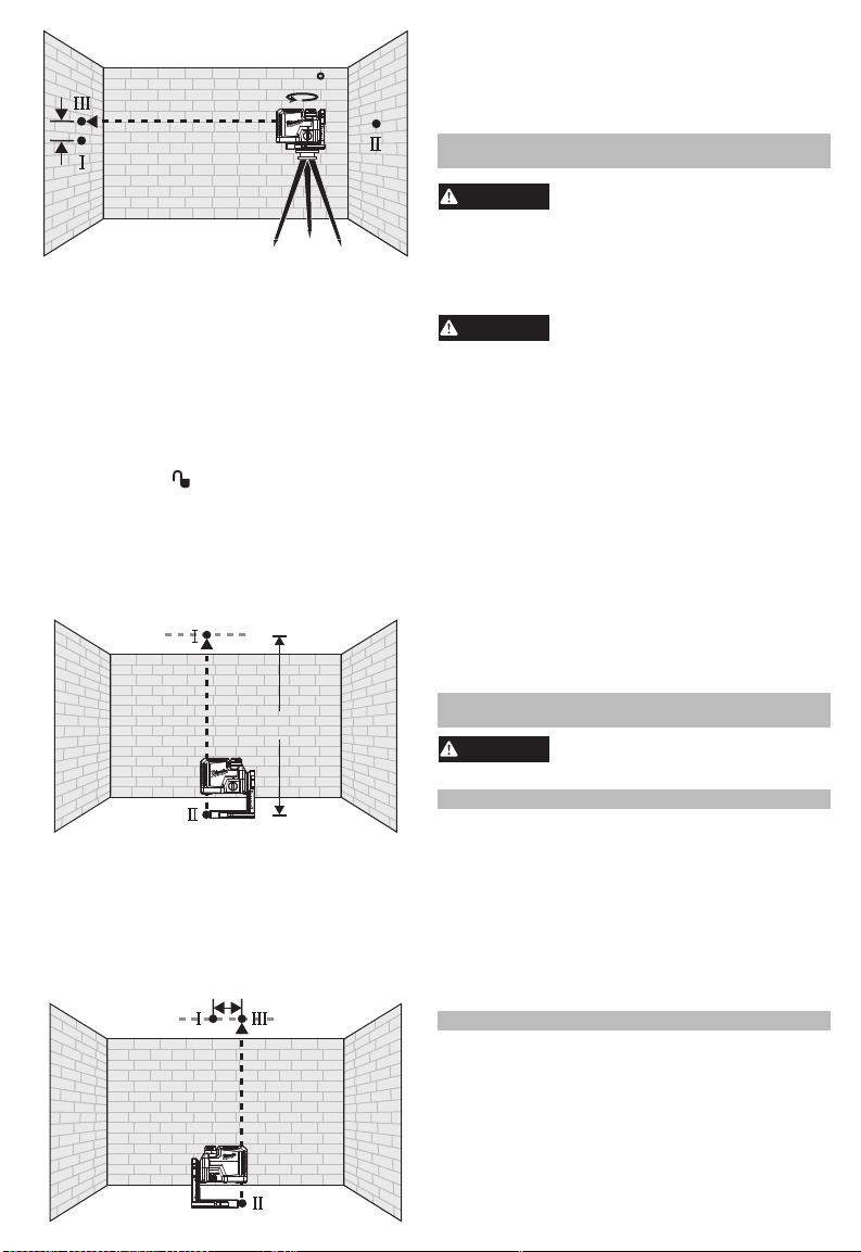
7. Rotate the tool 180° without changing the height,
allow it to self-level, and mark the center point of
the laser beam on wall A (point III). Point III should
be aligned as vertically above or below point I on
wall A as possible.
5
A
d
WARNING
WARNING
WARNING
d
8. The distance between points I and III on wall A is
the height deviation (d) of the tool. This distance
should not exceed 1/8" (max.) at 33' (1/2" at 132').
For the Measuring distance of 2 x 66' = 132', the maximum allowable deviation (d) is: 132' x ±1/8" ÷ 33' = ±1/2".
A free measuring distance of approximately 16.5'
between oor and ceiling on a rm surface is required
for this check.
1. Draw a straight line on the ceiling to use as a
2. Securely mount the tool within 1' of the oor.
3. Turn the tool to
4. Position the tool so that the bottom plumb point
5. Mark the center of the top plumb point with the refer-
Vertical Leveling Accuracy
reference line.
ON.
can be seen on the oor and the center of the top
plumb point is located on the reference line on the
ceiling. Allow the tool to self-level.
ence line on the ceiling (point I). Also, mark the center of the bottom plumb point on the oor (point II).
180
B
9. The distance between points I and III on the ceiling
is the deviation (d) of the tool. This distance should
not exceed 1/8" (max.) at 33'.
For the Measuring distance of 2 x 16.5' = 33', the
maximum allowable deviation (d) is: 33' x ±1/8"
÷ 33' = ±1/8".
MAINTENANCE
To reduce the risk of injury, always
ing any maintenance. Never disassemble the tool.
Maintain tools. If damaged, have the tool repaired
before use. Accidents may be caused by poorly
maintained tools.
your tool in liquid or allow a liquid to ow inside
them.
Clean dust and debris from any vents. Keep tool
clean, dry and free of oil or grease. Use only mild
soap and a damp cloth to clean, since certain cleaning agents and solvents are harmful to plastics
and other insulated parts. Some of these include
gasoline, turpentine, lacquer thinner, paint thinner, chlorinated cleaning solvents, ammonia and
household detergents containing ammonia. Never
use ammable or combustible solvents around tools.
Blow o loose particles with clean compressed air.
Carefully wipe the surface with a cotton swab moistened with water.
For repairs, return the tool, battery pack and charger
to the nearest authorized service center.
remove the battery before perform-
Maintain Laser Level
To reduce the risk of personal injury and damage, never immerse
Cleaning
Cleaning the Lenses
Repairs
16.5'
6. Rotate the tool 180°. Align the center point of the
laser beam directly onto the oor point II.
7. Position the tool to align the center of the top plumb
point onto the reference line on the ceiling. It may
be necessary to rotate the tool slightly to align.
Allow the tool to self-level.
8. Mark the center of the top plumb point on the
reference line on the ceiling (point III).
ACCESSORIES
Use tools only with specifically
any other accessories may create risk of injury.
1-800-SAWDUST (1.800.729.3878)
Monday-Friday, 7:00 AM - 6:30 PM CST
Contact Corporate After Sales Service Technical Support
with technical, service/repair, or warranty questions.
Email: metproductsupport@milwaukeetool.com
Become a Heavy Duty Club Member at
www.milwaukeetool.com to receive important
notications regarding your tool purchases.
Milwaukee Tool (Canada) Ltd
Monday-Friday, 7:00 AM - 4:30 PM CST
6
designated accessories. Use of
SERVICE - UNITED STATES
or visit www.milwaukeetool.com
SERVICE - CANADA
1.800.268.4015
or visit www.milwaukeetool.ca
 Loading...