

Page 1
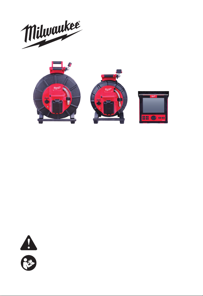
OPERATOR'S MANUAL
MANUEL de L'UTILISATEUR
MANUAL del OPERADOR
Cat. No. / No de cat.
2970-20: M18™ 500GB CONTROL HUB
2971-20: M18™ WIRELESS MONITOR
2973-20: 120' PIPELINE INSPECTION REEL
2974-20: 200' PIPELINE INSPECTION REEL
48-53-2970 - TABLET MOUNT
2970-20: M18™ Unité de contrôle 500GB
2971-20: M18™ Moniteur de Commande Sans Fil
2973-20: 36,5 M Touret de cable pour Inspection de canalisation
2974-20: 60,9 M Touret de cable pour Inspection de canalisation
48-53-2970 - Support de tablette
2970-20: M18 ™ Control Central de 500 GB
2971-20: M18 ™ Monitor inalámbrico
2973-20: Carrete de inspección de tubería de 36,5 M
2974-20: Carrete de inspección de tubería de 60,9 M
48-53-2970 - Montaje en tableta
WARNING To reduce the risk of injury, user must read and understand
operator's manual.
AVERTISSEMENT Afi n de réduire le risque de blessures, l'utilisateur
doit lire et bien comprendre le manuel.
ADVERTENCIA Para reducir el riesgo de lesiones, el usuario debe leer y
entender el manual.
Page 2

Page 3

OPERATOR'S MANUAL
Cat. No.
2970-20: M18™ 500GB CONTROL HUB
2971-20: M18™ WIRELESS MONITOR
2973-20: 120' PIPELINE INSPECTION REEL
2974-20: 200' PIPELINE INSPECTION REEL
48-53-2970 - TABLET MOUNT
English
Page 4

Page 5

GENERAL POWER TOOL SAFETY WARNINGS
provided with this power tool. Failure to follow all instructions listed below may result in
electric shock, re and/or serious injury. Save all warnings and instructions for future
reference. The term "power tool" in the warnings refers to your mains-operated (corded)
power tool or battery-operated (cordless) power tool.
Read all safety warnings, instructions, illustrations and specications
WORK SAFETY AREA
• Keep work area clean and well lit. Cluttered or dark areas invite accidents.
• Do not operate power tools in explosive atmospheres, such as in the presence
of ammable liquids, gases or dust. Power tools create sparks which may ignite the
dust or fumes.
• Keep children and bystanders away while operating a power tool. Distractions
can cause you to lose control.
ELECTRICAL SAFETY
• Power tool plugs must match the outlet. Never modify the plug in any way. Do
not use any adapter plugs with earthed (grounded) power tools. Unmodied plugs
and matching outlets will reduce risk of electric shock.
• Avoid body contact with earthed or grounded surfaces, such as pipes, radiators,
ranges and refrigerators. There is an increased risk of electric shock if your body is
earthed or grounded.
• Do not expose power tools to rain or wet conditions. Water entering a power tool
will increase the risk of electric shock.
• Do not abuse the cord. Never use the cord for carrying, pulling or unplugging
the power tool. Keep cord away from heat, oil, sharp edges or moving parts.
Damaged or entangled cords increase the risk of electric shock.
• When operating a power tool outdoors, use an extension cord suitable for
outdoor use. Use of a cord suitable for outdoor use reduces the risk of electric shock.
• If operating a power tool in a damp location is unavoidable, use a ground fault
circuit interrupter (GFCI) protected supply. Use of an GFCI reduces the risk of
electric shock.
PERSONAL SAFETY
• Stay alert, watch what you are doing and use common sense when operating a
power tool. Do not use a power tool while you are tired or under the inuence of
drugs, alcohol or medication. A moment of inattention while operating power tools
may result in serious personal injury.
• Use personal protective equipment. Always wear eye protection. Protective
equipment such as a dust mask, non-skid safety shoes, hard hat or hearing protection
used for appropriate conditions will reduce personal injuries.
• Prevent unintentional starting. Ensure the switch is in the off position before
connecting to power source and/or battery pack, picking up or carrying the tool.
Carrying power tools with your nger on the switch or energizing power tools that have
the switch on invites accidents.
• Remove any adjusting key or wrench before turning the power tool on. A wrench
or a key left attached to a rotating part of the power tool may result in personal injury.
• Do not overreach. Keep proper footing and balance at all times. This enables
better control of the power tool in unexpected situations.
1
Page 6

• Dress properly. Do not wear loose clothing or jewelry. Keep your hair and
clothing away from moving parts. Loose clothes, jewelry or long hair can be caught
in moving parts.
• If devices are provided for the connection of dust extraction and collection
facilities, ensure these are connected and properly used. Use of dust collection
can reduce dust-related hazards.
• Do not let familiarity gained from frequent use of tools allow you to become
complacent and ignore tool safety principles. A careless action can cause severe
injury within a fraction of a second.
POWER TOOL USE AND CARE
• Do not force the power tool. Use the correct power tool for your application. The
correct power tool will do the job better and safer at the rate for which it was designed.
• Do not use the power tool if the switch does not turn it on and off. Any power tool
that cannot be controlled with the switch is dangerous and must be repaired.
• Disconnect the plug from the power source and/or remove the battery pack,
if detachable, from the power tool before making any adjustments, changing
accessories, or storing power tools. Such preventive safety measures reduce the
risk of starting the power tool accidentally.
• Store idle power tools out of the reach of children and do not allow persons
unfamiliar with the power tool or these instructions to operate the power tool.
Power tools are dangerous in the hands of untrained users.
• Maintain power tools and accessories. Check for misalignment or binding of
moving parts, breakage of parts and any other condition that may affect the
power tool's operation. If damaged, have the power tool repaired before use.
Many accidents are caused by poorly maintained power tools.
• Keep cutting tools sharp and clean. Properly maintained cutting tools with sharp
cutting edges are less likely to bind and are easier to control.
• Use the power tool, accessories and tool bits etc. in accordance with these
instructions, taking into account the working conditions and the work to be
performed. Use of the power tool for operations different from those intended could
result in a hazardous situation.
• Keep handles and grasping surfaces dry, clean and free from oil and grease.
Slippery handles and grasping surfaces do not allow for safe handling and control of
the tool in unexpected situations.
BATTERY TOOL USE AND CARE
• Recharge only with the charger specied by the manufacturer. A charger that is
suitable for one type of battery pack may create a risk of re when used with another
battery pack.
• Use power tools only with specically designated battery packs. Use of any other
battery packs may create a risk of injury and re.
• When battery pack is not in use, keep it away from other metal objects, like
paper clips, coins, keys, nails, screws or other small metal objects, that can
make a connection from one terminal to another. Shorting the battery terminals
together may cause burns or a re.
• Under abusive conditions, liquid may be ejected from the battery; avoid
contact. If contact accidentally occurs, ush with water. If liquid contacts eyes,
additionally seek medical help. Liquid ejected from the battery may cause irritation
or burns.
2
Page 7

• Do not use a battery pack or tool that is damaged or modified. Damaged or
modied batteries may exhibit unpredictable behavior resulting in re, explosion or risk
of injury.
• Do not expose a battery pack or tool to re or excessive temperature. Exposure
to re or temperature above 265°F (130°C) may cause explosion.
• Follow all charging instructions and do not charge the battery pack or tool
outside the temperature range specied in the instructions. Charging improperly
or at temperatures outside the specied range may damage the battery and increase
the risk of re.
SERVICE
• Have your power tool serviced by a qualied repair person using only identical
replacement parts. This will ensure that the safety of the power tool is maintained.
• Never service damaged battery packs. Service of battery packs should only be
performed by the manufacturer or authorized service providers.
SPECIFIC SAFETY RULES FOR PIPELINE INSPECTION
SYSTEMS
• Use latex or rubber gloves, goggles, face shields, protective clothing, and
respirator when chemicals, bacteria or other toxic or infectious substances are
suspected to be in a drain line. Drains may contain chemicals, bacteria and other
substances that may cause burns, be toxic or infectious or may result in other serious
personal injury.
• Practice good hygiene. Do not eat or smoke while handling or operating the tool.
After handling or operating equipment, use hot, soapy water to wash hands and
other body parts exposed to drain contents. This will help reduce the risk of health
hazards due to exposure to toxic or infectious material.
• Always check the work area before beginning a job. Do not allow cable to
contact electrical, chemical, or moving hazards.
• Do not use the cable to clear clogs or move obstructions. This is not a drain
cleaner!
• Inspect cable for wear and damage before use. Do not twist, kink or over bend
cables. Replace a worn or damaged cable before use.
• To reduce the risk of re, personal injury, and product damage due to a short
circuit, never immerse your tool, battery pack or charger in fluid or allow a
uid to ow inside them. Corrosive or conductive uids, such as seawater, certain
industrial chemicals, and bleach or bleach containing products, etc., can cause a short
circuit.
• Recharge battery packs only with the charger specified for the battery. For
specic charging instructions, read the operator's manual supplied with your charger
and battery.
• CAUTION Use care when transporting this tool when the reel and backpack are
connected. Tipping may occur.
• Always use common sense and be cautious when using tools. It is not possible
to anticipate every situation that could result in a dangerous outcome. Do not use
this tool if you do not understand these operating instructions or you feel the work is
beyond your capability; contact Milwaukee Tool or a trained professional for additional
information or training.
• Maintain labels and nameplates. These carry important information. If unreadable or
missing, contact a MILWAUKEE service facility for a free replacement.
3
Page 8
•
other construction activities contains chemicals known to cause cancer, birth defects
or other reproductive harm. Some examples of these chemicals are:
• lead from lead-based paint
• crystalline silica from bricks and cement and other masonry products, and
• arsenic and chromium from chemically treated lumber.
Your risk from these exposures varies, depending on how often you do this type of work.
To reduce your exposure to these chemicals: work in a well-ventilated area, and work with
approved safety equipment, such as those dust masks that are specially designed to lter
out microscopic particles.
Some dust created by power sanding, sawing, grinding, drilling, and
FEDERAL COMMUNICATIONS COMMISSION
cause radio interference in which case the user may be required to take adequate
measures.
This equipment has been tested and found to comply with the limits for a Class A digital
device, pursuant to Part 15 of the FCC Rules. These limits are designed to provide
reasonable protection against harmful interference when the equipment is operated
in a commercial environment. This equipment generates, uses, and can radiate radio
frequency energy and, if not installed and used in accordance with the instruction manual,
may cause harmful interference to radio communications. Operation of this equipment
in a residential area is likely to cause harmful interference in which case the user will be
required to correct the interference at his own expense.
This device complies with Part 15 of the FCC Rules.
Operation is subject to the following two conditions:
(1) this device may not cause harmful interference, and
(2) this device must accept any interference received, including interference that may
cause undesired operation.
This is a class A product. In a domestic environment this product may
SYMBOLOGY
Volts
Direct Current
Federal Communications Commission
Do not allow battery to contact corrosive or conductive uid
To prevent electric shock, do not allow product to contact live electrical
parts
Chemical Burn Hazard - Keep away from children
4
Page 9
SPECIFICATIONS
Volts ……………………………………………. 18 DC
Battery Type…………………………………… M18™
Charger Type…………………………………… M18™
Recommended Ambient
Operating Temperature………………………. 0°F to 125°F
M18™ BATTERIES
charging instructions, read the operator's manual supplied with your charger and
battery.
Removing/Inserting the Battery
To remove the battery, push in the release buttons and pull the battery pack away from
the tool.
To insert the battery, slide the pack into the body of the tool. Make sure it latches
securely into place.
may be hazardous.
Recharge only with the charger specied for the battery. For specic
Always remove battery pack before changing or removing accessories.
Only use accessories specically recommended for this tool. Others
ONE-KEY™
To learn more about the ONE-KEY™ functionality for this tool, please reference the Quick
Start guide included with this product or go to milwaukeetool.com/One-Key. To download
the ONE-KEY™ app, visit the App Store or Google Play Store from your smart device.
ONE-KEY™ Indicator
Solid Blue Wireless mode is active and ready to be congured via the ONE-
KEY™ app.
Blinking Blue Is actively communicating with the ONE-KEY™ app.
Blinking Red Tool is in security lockout and can be unlocked by the owner via the
ONE-KEY™ app.
INTERNAL BATTERY
Chemical Burn Hazard. This device contains a lithium button/coin
cell battery. A new or used battery can cause severe internal burns
and lead to death in as little as 2 hours if swallowed or enters the
body. Always secure the battery cover. If it does not close securely,
stop using the device, remove the batteries, and keep it away from
children. If you think batteries may have been swallowed or entered
the body, seek immediate medical attention.
An internal battery is used to facilitate full ONE-KEY™ functionality.
To replace the battery:
1. Remove the battery pack.
2. Remove the screw(s) and open the battery door.
3. Remove the old battery, keep it away from children, and dispose of it properly.
4. Insert the new battery (3V CR2032), with the positive side facing up.
Close the battery door and tighten the screw securely.
5
Page 10

MAINTENANCE
the battery pack from the charger or tool before performing any maintenance.
Never disassemble the tool, battery pack or charger. Contact a MILWAUKEE service
facility for ALL repairs.
To reduce the risk of injury, always unplug the charger and remove
MAINTAINING TOOL
Keep your tool, battery pack and charger in good repair by adopting a regular
maintenance program. Inspect your tool for issues such as undue noise, misalignment or
binding of moving parts, breakage of parts, or any other condition that may affect the tool
operation. Return the tool, battery pack, and charger to a MILWAUKEE service facility for
repair. After six months to one year, depending on use, return the tool, battery pack and
charger to a MILWAUKEE service facility for inspection.
If the tool does not start or operate at full power with a fully charged battery pack, clean
the contacts on the battery pack. If the tool still does not work properly, return the tool,
charger and battery pack, to a MILWAUKEE service facility for repairs.
your tool, battery pack or charger in liquid or allow a liquid to ow inside them.
To reduce the risk of personal injury and damage, never immerse
CLEANING
Clean dust and debris from vents. Keep handles clean, dry and free of oil or grease. Use
only mild soap and a damp cloth to clean, since certain cleaning agents and solvents are
harmful to plastics and other insulated parts. Some of these include gasoline, turpentine,
lacquer thinner, paint thinner, chlorinated cleaning solvents, ammonia and household
detergents containing ammonia. Never use ammable or combustible solvents around
tools.
REPAIRS
For repairs, return the tool, battery pack and charger to the nearest service center.
ACCESSORIES
For a complete listing of accessories, go online to www.milwaukeetool.com or contact a
distributor.
Use only recommended accessories. Others may be hazardous.
SERVICE – UNITED STATES
1-800-SAWDUST
Monday-Friday, 7:00 AM - 6:30 PM CST
or visit www.milwaukeetool.com
Contact Corporate After Sales Service Technical Support with technical, service/repair, or
warranty questions.
Email: [email protected]
Become a Heavy Duty Club Member at www.milwaukeetool.com to receive important
notications regarding your tool purchases.
(1.800.729.3878)
SERVICE - CANADA
Milwaukee Tool (Canada) Ltd
1.800.268.4015
Monday-Friday, 7:00 AM - 4:30 PM CST
or visit www.milwaukeetool.ca
6
Page 11

LIMITED WARRANTY USA & CANADA
Every MILWAUKEE power tool* (see exceptions below) is warranted to the original
purchaser only to be free from defects in material and workmanship. Subject to certain
exceptions, MILWAUKEE will repair or replace any part on an electric power tool
which, after examination, is determined by MILWAUKEE to be defective in material or
workmanship for a period of ve (5) years** after the date of purchase unless otherwise
noted. Return of the power tool to a MILWAUKEE factory Service Center location or
MILWAUKEE Authorized Service Station, freight prepaid and insured, is required. A copy
of the proof of purchase should be included with the return product. This warranty does not
apply to damage that MILWAUKEE determines to be from repairs made or attempted by
anyone other than MILWAUKEE authorized personnel, misuse, alterations, abuse, normal
wear and tear, lack of maintenance, or accidents.
Normal Wear: Many power tools need periodic parts replacement and service to achieve
best performance. This warranty does not cover repair when normal use has exhausted the
life of a part including, but not limited to, chucks, brushes, cords, saw shoes, blade clamps,
O-rings, seals, bumpers, driver blades, pistons, strikers, lifters, and bumper cover washers.
*This warranty does not cover Air Nailers & Staplers; Airless Paint Sprayer; Cordless Battery
Packs; Gasoline Driven Portable Power Generators; Hand Tools; Hoist – Electric, Lever
& Hand Chain; M12™ Heated Gear; Reconditioned Product; and Test & Measurement
Products. There are separate and distinct warranties available for these products.
**The warranty period for Job Site Radios, M12™ Power Port, M18™ Power Source,
Jobsite Fan and Trade Titan™ Industrial Work Carts is one (1) year from the date of
purchase. The warranty period for the Drain Cleaning Cables is two (2) years from
the date of purchase. The warranty period for the M18™ Compact Heat Gun and the
8 Gallon Dust Extractor is three (3) years from the date of purchase. The warranty
period for the LED in the LED Work Light and the LED Upgrade Bulb for the Work
Light is the lifetime of the product subject to the limitations above. If during normal
use the LED or LED Bulb fails, the part will be replaced free of charge.
Warranty Registration is not necessary to obtain the applicable warranty on a MILWAUKEE
power tool product. The manufacturing date of the product will be used to determine the
warranty period if no proof of purchase is provided at the time warranty service is requested.
ACCEPTANCE OF THE EXCLUSIVE REPAIR AND REPLACEMENT REMEDIES
DESCRIBED HEREIN IS A CONDITION OF THE CONTRACT FOR THE PURCHASE OF
EVERY MILWAUKEE PRODUCT. IF YOU DO NOT AGREE TO THIS CONDITION, YOU
SHOULD NOT PURCHASE THE PRODUCT. IN NO EVENT SHALL MILWAUKEE BE
LIABLE FOR ANY INCIDENTAL, SPECIAL, CONSEQUENTIAL OR PUNITIVE DAMAGES,
OR FOR ANY COSTS, ATTORNEY FEES, EXPENSES, LOSSES OR DELAYS ALLEGED
TO BE AS A CONSEQUENCE OF ANY DAMAGE TO, FAILURE OF, OR DEFECT IN ANY
PRODUCT INCLUDING, BUT NOT LIMITED TO, ANY CLAIMS FOR LOSS OF PROFITS.
SOME STATES DO NOT ALLOW THE EXCLUSION OR LIMITATION OF INCIDENTAL
OR CONSEQUENTIAL DAMAGES, SO THE ABOVE LIMITATION OR EXCLUSION MAY
NOT APPLY TO YOU. THIS WARRANTY IS EXCLUSIVE AND IN LIEU OF ALL OTHER
EXPRESS WARRANTIES, WRITTEN OR ORAL. TO THE EXTENT PERMITTED BY
LAW, MILWAUKEE DISCLAIMS ANY IMPLIED WARRANTIES, INCLUDING WITHOUT
LIMITATION ANY IMPLIED WARRANTY OF MERCHANTABILITY OR FITNESS FOR
A PARTICULAR USE OR PURPOSE; TO THE EXTENT SUCH DISCLAIMER IS NOT
PERMITTED BY LAW, SUCH IMPLIED WARRANTIES ARE LIMITED TO THE DURATION
OF THE APPLICABLE EXPRESS WARRANTY AS DESCRIBED ABOVE. SOME STATES
DO NOT ALLOW LIMITATIONS ON HOW LONG AN IMPLIED WARRANTY LASTS,
7
Page 12

SO THE ABOVE LIMITATION MAY NOT APPLY TO YOU, THIS WARRANTY GIVES YOU
SPECIFIC LEGAL RIGHTS, AND YOU MAY ALSO HAVE OTHER RIGHTS WHICH VARY
FROM STATE TO STATE.
This warranty applies to product sold in the U.S.A. and Canada only.
Please consult the ‘Service Center Search' in the Parts & Service section of
MILWAUKEE's website www.milwaukeetool.com or call 1.800.SAWDUST
(1.800.729.3878) to locate your nearest service facility for warranty and non-warranty
service on a Milwaukee electric power tool.
LIMITED WARRANTY - MEXICO, CENTRAL AMERICA &
CARIBBEAN
TECHTRONIC INDUSTRIES' warranty is for 5 years since the original purchase date.
This warranty card covers any defect in material and workmanship on this Product.
To make this warranty valid, present this warranty card, sealed/stamped by the distributor
or store where you purchased the product, to the Authorized Service Center (ASC). Or, if
this card has not been sealed/stamped, present the original proof of purchase to the ASC.
Call toll-free1 01 (800) 030-7777 to nd the nearest ASC, for service, parts, accessories
or components.
Procedure to make this warranty valid
Take the product to the ASC, along with the warranty card sealed/stamped by the
distributor or store where you purchased the product, and any faulty piece or component
will be replaced without cost for you. We will cover all freight costs relative with this
warranty process.
Exceptions
This warranty is not valid in the following situations
a) When the product is used in a different manner from the end-user guide or instruction
manual.
b) When the conditions of use are not normal.
c) When the product was modied or repaired by people not authorized by TECHTRONIC
INDUSTRIES.
Note: If cord set is damaged, it should be replaced by an Authorized Service Center to
avoid electric risks.
SERVICE AND ATTENTION CENTER
Call to 01 (800) 030-7777
IMPORTED AND COMMERCIALIZED BY
TECHTRONIC INDUSTRIES MEXICO, SA DE CV
Av President Masarik #29 piso 7, Col. Polanco V Sección
CP 11560, Deleg. Miguel Hidalgo, CDMX
Model: _______________________________________
Date of Purchase: ______________________________
Distributor or Store Stamp: _______________________
8
Page 13

Table of Content
1. Introduction..................................................................................................................11
1.1 The M18™ PIPELINE INSPECTION SYSTEM....................................................11
1.2 M18™ WIRELESS MONITOR Overview.............................................................11
1.3 M18™ 500GB CONTROL HUB Overview............................................................11
1.4 PIPELINE INSPECTION REEL Overview............................................................12
2. M18™ WIRELESS MONITOR.....................................................................................13
2.1 M18™ WIRELESS MONITOR Overview.............................................................13
2.2 Setup of the M18™ WIRELESS MONITOR.........................................................14
2.2.1 Power on/off.............................................................................................14
2.2.2 M18™ WIRELESS MONITOR First Time Setup.......................................14
2.2.3 Navigating through the Settings Menu......................................................14
2.2.4 Setting the M18™ WIRELESS MONITOR LANGUAGE...........................15
2.2.5 Setting the DATE & TIME..........................................................................15
2.2.6 Setting the UNITS of Measure..................................................................16
2.2.7 Setting the SONDE FREQUENCY............................................................17
2.2.8 Setting the COMPANY NAME..................................................................18
2.2.9 VIDEO and IMAGE SETTINGS................................................................19
2.2.10 CONNECTION SETTINGS....................................................................20
2.2.11 M18™ BATTERY....................................................................................23
2.2.12 Setting the LCD SCREEN SETTINGS....................................................24
2.3 Using the M18™ WIRELESS MONITOR.............................................................25
2.3.1 Using JOBS..............................................................................................26
2.3.2 Creating a Video Recording and Image Capturing....................................27
2.3.3 EXPORT JOB...........................................................................................29
2.3.4 Adjusting the CAMERA LIGHT..................................................................30
2.3.5 IMAGE ENHANCE...................................................................................30
2.3.6 ZOOM & PAN...........................................................................................30
2.3.7 Screen ROTATE.......................................................................................32
2.3.8 LINE TRACE............................................................................................32
2.3.9 SONDE....................................................................................................33
2.3.10 GALLERY Overview...............................................................................34
2.3.11 Playback Highlights................................................................................35
2.3.12 Playing videos and viewing pictures.......................................................36
2.3.13 Rewind and Fast Forward.......................................................................36
2.3.14 Trimming Video Files..............................................................................37
2.3.15 Recording Audio.....................................................................................39
2.3.16 Speaker Volume.....................................................................................39
2.3.17 Delete Files............................................................................................39
Page 14

2.3.18 Using LABELS........................................................................................41
2.4 Factory Reset & Firmware Updates – M18™ WIRELESS MONITOR..................44
2.4.1 Factory Reset – M18™ WIRELESS MONITOR........................................44
2.4.2 Firmware Updates – M18™ WIRELESS MONITOR.................................44
3. M18™ 500GB CONTROL HUB...................................................................................46
3.1 Overview..............................................................................................................46
3.2 Installing and removing the M18™ 500GB CONTROL HUB................................47
3.3 Using the M18™ 500GB CONTROL HUB...........................................................48
3.3.1 Power on/off.............................................................................................48
3.3.2 USB Ports.................................................................................................48
3.3.3 Grounding Post........................................................................................49
3.3.4 Distance Counter Reset...........................................................................49
3.3.5 Camera Test Port......................................................................................49
3.4 Formatting the M18™ CONTROL HUB INTERNAL and THUMB DRIVEs...........50
3.5 FACTORY RESET & SYSTEM UPDATES – M18™ 500GB CONTROL HUB.....51
3.5.1 FACTORY RESET - M18™ 500GB CONTROL HUB...............................51
3.5.2 SYSTEM UPDATE - M18™ 500GB CONTROL HUB...............................53
4. PIPELINE INSPECTION REEL...................................................................................55
4.1 200' PIPELINE INSPECTION REEL Overview....................................................55
4.2 120' PIPELINE INSPECTION REEL Overview....................................................56
4.3 Installing the Backpack Plate...............................................................................57
4.4 Mounting the M18™ WIRELESS MONITOR.......................................................59
4.5 Using the PIPELINE INSPECTION REEL...........................................................60
4.6 Push Cable..........................................................................................................61
5. Camera Heads and Spring Assembly..........................................................................62
5.1 Camera Heads....................................................................................................62
5.2 Parts of the Spring Assembly...............................................................................63
5.3 Removing and Installing the Camera Heads........................................................63
5.3.1 Camera Head Removal............................................................................63
5.3.2 Camera Head Installation.........................................................................64
5.4 Removing and Installing the Spring Assembly.....................................................64
5.4.1 Spring Assembly Removal........................................................................64
5.4.2 Spring Assembly Installation.....................................................................65
5.5 Camera Skids and Protective Covers..................................................................65
5.5.1 The Protective Covers..............................................................................65
5.5.2 Removing the Protective Cover................................................................66
5.5.3 Installing the Protective Covers................................................................66
5.5.4 Camera Skids...........................................................................................66
5.5.5 Installing the Camera Skid........................................................................67
6. Service & Support........................................................................................................68
Page 15
1 Introduction
1. Introduction
1.1 The M18™ PIPELINE INSPECTION SYSTEM
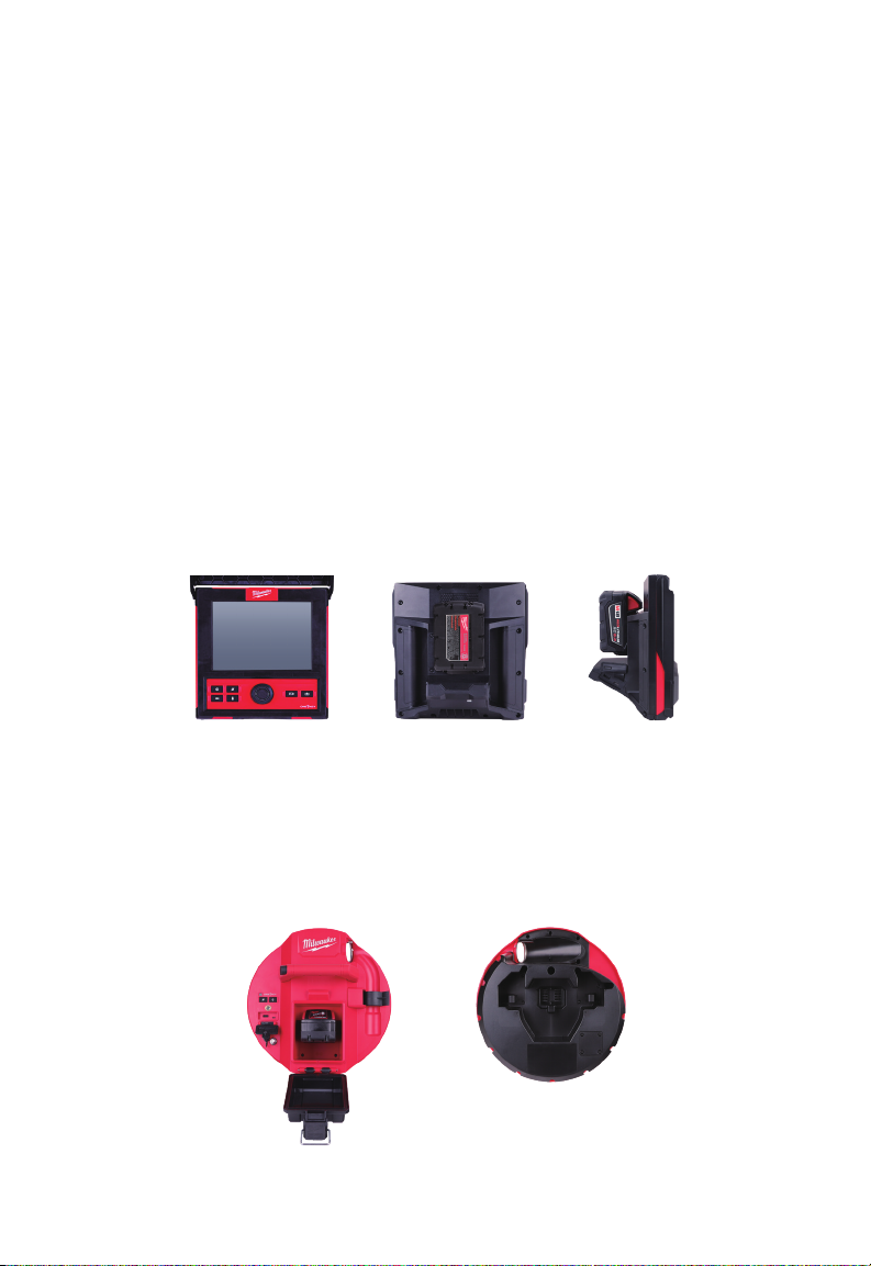
The systems consist of three major modules, the M18™ WIRELESS MONITOR, the
M18™ 500GB CONTROL HUB, and the PIPELINE INSPECTION REELS.
1.2 M18™ WIRELESS MONITOR Overview
The M18™ WIRELESS MONITOR allows for viewing the raw video from the camera
head, recording videos and capturing picture images and playback functions of video and
picture les. During the recording of videos, audio comments can be captured through the
internal microphone, and text comments can be added via the labels option. These text
comments will appear in the recorded video and will show in the pictures along with the
system time, system date and distance of deployed push cable.
Note that the WIRELESS MONITOR or tablet running the Milwaukee® Pipeline Inspection
App must be connected to the M18 ™ 500GB CONTROL HUB to create video recordings
or capture pictures. Both the video and picture les are stored in the CONTROL HUB
INTERNAL DRIVE or CONTROL HUB THUMB DRIVE.
Front View Rear View Side View
1.3 M18™ 500GB CONTROL HUB Overview
The M18™ 500GB CONTROL HUB is the brain of the PIPELINE INSPECTION SYSTEM.
The M18™ WIRELESS MONITOR or tablet running the Milwaukee® Pipeline Inspection
App connects to the CONTROL HUB to receive the recording video and captured
pictures. Both are stored in the CONTROL HUB INTERNAL DRIVE.
Front View Rear View
11
Page 16
1 Introduction
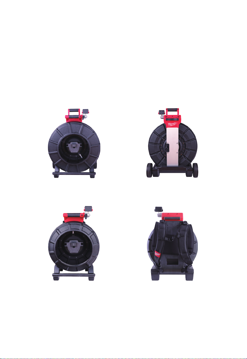
1.4 PIPELINE INSPECTION REEL Overview
The PIPELINE INSPECTION REEL stores and controls the deployment of the push cable.
The reels are available in two sizes, the 120' reel mostly used in pipe sizes from two to
six inches and the larger 200' reel mostly used in pipe sizes from three to ten inches.
Both sizes include push cable with a spring assembly that the self-leveling camera head
mounts on. The M18™ WIRELESS MONITOR and M18™ 500GB CONTROL HUB will
work with both size reels.
Both sizes can be used either in the vertical upright position or on its side in a horizontal
position. The 120' reel has a mounting plate on the back to attach backpack straps.
200' PIPELINE INSPECTION REEL Overview
Front view Rear view
120' PIPELINE INSPECTION REEL Overview
Front view Rear view
12
Page 17
2 M18™ WIRELESS MONITOR
2. M18™ WIRELESS MONITOR
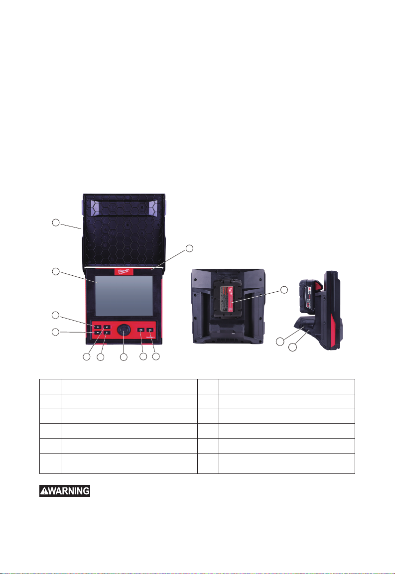
2.1 M18™ WIRELESS MONITOR Overview
The M18™ WIRELESS MONITOR provides viewing, recording, and playback functions of
video and picture les. During the recording of videos audio comments can be captured
through the internal microphone, and text comments can be added via the LABELS
feature.
Note that the WIRELESS MONITOR or tablet running the Milwaukee® Pipeline Inspection
App must be connected to the M18™ 500GB CONTROL HUB in order to create a video
recording or capture pictures. Both the video and picture les are stored in the CONTROL
HUB INTERNAL DRIVE.
1
10
2
11
3
4
5
6 7
8 9
12a
12b
1. Sunshield 7. Navigation Dial
2. LCD 8. Record video button
3. Power button 9. Picture capture button
4. Back Button 10. Internal microphone
5. Distance reset button 11. M18™ BATTERY mounting area
6. Microphone button 12.
12a USB-A port
12b USB-C port
To reduce the risk of short circuit, when setting tool or battery down,
do not allow battery to contact corrosive or conductive uid.
13
Page 18

2 M18™ WIRELESS MONITOR
2.2 Setup of the M18™ WIRELESS MONITOR
This section of the manual covers setting up the features and options of the M18™
WIRELESS MONITOR. Mounting the WIRELESS MONITOR to the PIPELINE
INSPECTION REEL is covered in section 4.4 of this manual.
2.2.1 Power on/off
Press the Power button on the M18™ WIRELESS MONITOR. The buttons and
navigation dial will illuminate, showing that the power is on. The WIRELESS MONITOR
icon will appear in the status bar of the LCD along with the battery state.
2.2.2 M18™ WIRELESS MONITOR First Time Setup
All the settings are saved into the M18™ WIRELESS MONITOR's memory and will
remain there until changed. Note that the settings will be lost if the unit is reset to factory
defaults or by formatting the M18™ 500GB CONTROL HUB INTERNL DRIVE. The
PIPELINE INSPECTION REEL with camera does not need to be connected to the for the
rst-time setup.
These initial WIRELESS MONITOR settings will set the UNITS of distance measurement,
DATE & TIME formats, SONDE frequencies, VIDEO, and IMAGE quality, CONNECTION
SETTINGS and LANGUAGE.
These settings can also be performed through a tablet running the Milwaukee® Pipeline
Inspection App.
2.2.3 Navigating through the Settings Menu
Navigation Dial - Turn the navigation dial clockwise or counter-clockwise
to move through the menus. While rotating the Navigation Dial, the position/
menu items will be highlighted by the red cursor line.
Press the Navigation Dial to select and accept the setup menu options.
Back Button - Pressing the Back button while in any menu or sub-menu
will take the screen back to the previous menu. Press the Back Button
repeatedly to return to the main viewing screen.
14
Page 19
2 M18™ WIRELESS MONITOR
CANCEL OK
2.2.4 Setting the M18™ WIRELESS MONITOR LANGUAGE
It is recommended to set your LANGUAGE rst so that the other menus can be easily
read and understood.
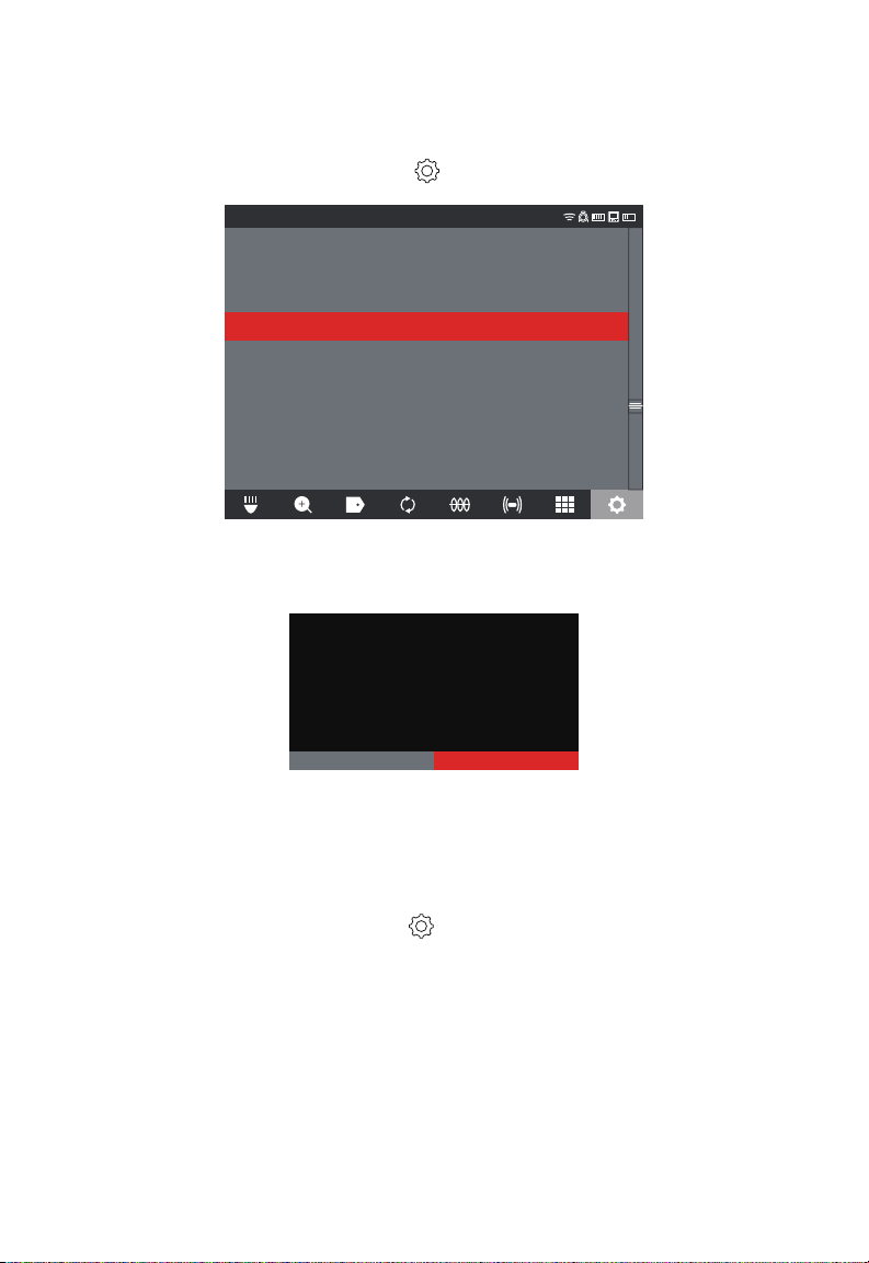
1. Turn the Navigation Dial to SETTINGS , press the navigation dial.
2. Turn the navigation dial to LANGUAGE, press to enter the LANGUAGE sub-menu.
SETTINGS
SCREEN SETTINGS
DATE & TIME
UNITS
Feet
LANGUAGE
English
MANAGE JOBS
2019/05/10 6 FILES
SYSTEM UPDATE
FACTORY RESET
ABOUT
SERVICE & SUPPORT
3. Turn the navigation dial to select the desired LANGUAGE and press the navigation
dial.
4. Turn the navigation dial and press on OK to start the LANGUAGE change.
The control modules settings have been
changed. These changes will take effect
only after the control module has been
restarted.
SETTINGS
5. The system will reboot and start in the LANGUAGE selected.
2.2.5 Setting the DATE & TIME
The system offers DATE FORMATSs of MM/DD/YYYY, DD/MM/YYYY and YYYY/MM/DD
with 12-Hour or 24-Hour TIME FORMATs.
1. Turn the navigation dial to SETTINGS
2. Turn the navigation dial to DATE & TIME, press to enter the DATE & TIME sub-menu.
3. Turn the navigation dial to DATE FORMAT, press the navigation dial. Use the
navigation dial to select the desired DATE FORMAT and press the navigation dial to
accept. Repeat the same steps selecting the TIME FORMAT.
press the navigation dial.
,
15
Page 20
2 M18™ WIRELESS MONITOR
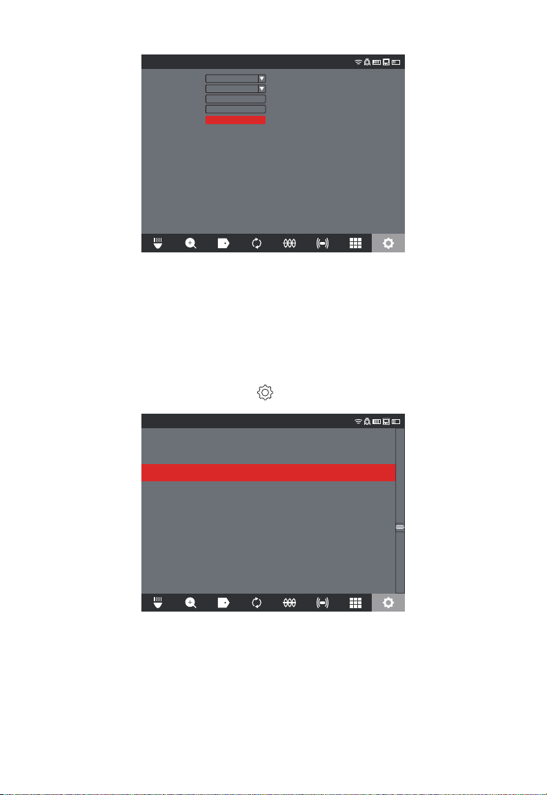
SETTINGS
DATE FORMAT
TIME FORMAT
DATE SET
TIME SET
YYYY/MM/DD
24 HOUR
2019 / 10 / 23
16 : 04 : 35
SAVE
4. Now use the navigation dial to enter the DATE and TIME values.
5. Turn the navigation dial to select SAVE and press the navigation dial.
The DATE & TIME are now set, and you will be returned to the SETTINGS menu.
If using a tablet running the Milwaukee® Pipeline Inspection App, the DATE & TIME are
taken from the tablet.
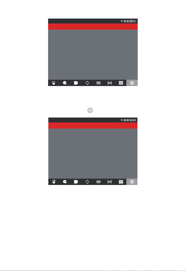
2.2.6 Setting the UNITS of Measure
1. Turn the navigation dial to SETTINGS , press the navigation dial.
2. Turn the navigation dial to UNITS, press to enter the sub-menu.
SETTINGS
SCREEN SETTINGS
DATE & TIME
UNITS
Feet
LANGUAGE
English
2019/05/10 6 FILES
SYSTEM UPDATE
FACTORY RESET
ABOUT
SERVICE & SUPPORT
3. Turn the navigation dial to select Feet or Meter and press the navigation dial.
16
Page 21
2 M18™ WIRELESS MONITOR
SETTINGS
Feet
Meter
The UNITS of measures are now set, and you will be returned to the SETTINGS menu.
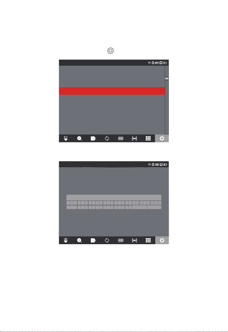
2.2.7 Setting the SONDE FREQUENCY
1. Turn the navigation dial to SETTINGS , press the navigation dial.
2. Turn the navigation dial to SONDE FREQUENCY, press to enter the sub-menu.
SETTINGS
512Hz
640Hz
33kHz
3. Turn the navigation dial to select the desired sonde frequency of 512Hz, 640Hz or
33kHz, press the navigation dial. The sonde frequency is now selected and you will be
returned to the settings sub-menu.
17
Page 22
2 M18™ WIRELESS MONITOR
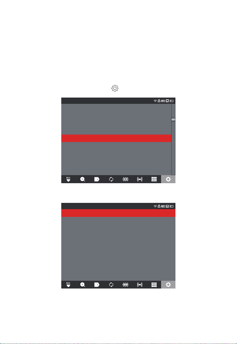
2.2.8 Setting the COMPANY NAME
This setting saves a COMPANY NAME in the system's memory. The COMPANY NAME
will splash on the video recordings start for 5 seconds and appear in all JPEG images.
1. Turn the navigation dial to SETTINGS , press the navigation dial.
2. Turn the navigation dial to COMPANY NAME, press to enter the sub-menu.
SETTINGS
MANAGE JOBS
SONDE FREQUENCY
640Hz
LABEL SETTINGS
MANAGE JOBS
2019/05/10 6 FILES
COMPANY NAME
VIDEO SETTINGS
1080P 30FPS
IMAGE SETTINGS
1920x1080
FORMAT DISK
CONNECTION SETTINGS
MTCAM_02938B284
CAMERA SETTINGS
3. Use the navigation dial to navigate the on-screen keyboard pressing the navigation
dial to accept each keyboard character.
SETTINGS
A B C D E F G H I J K L M N O P Q R S T U VWX Y Z
SPACE
1 2 3 4 5 6 7 8 9 0
MILWAUKEE
. ,
-
? !
DELETE
ENTER
4. When nished with the COMPANY NAME, navigate to the ENTER key, and press the
navigation dial.
5. Select SAVE or cancel to continue.
18
Page 23
2 M18™ WIRELESS MONITOR
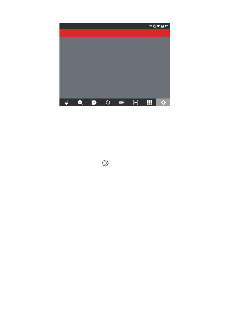
2.2.9 VIDEO and IMAGE SETTINGS
VIDEO SETTINGS
This setting allows for the selection of the video resolution. The video resolution will affect
the video quality, which in turn affects the size of the video le. The choices for resolution
and frames per second (FPS) are:
VIDEO SETTING choices - 1080p with 30 frames per second or 15 frames per second,
720p with 30 frames per second or 15 frames per second or 480p with 30 frames per
second or 15 frames per second
1. Turn the navigation dial to SETTINGS
, press the navigation dial.
2. Turn the navigation dial to VIDEO SETTINGS, press to enter the sub-menu.
SETTINGS
MANAGE JOBS
SONDE FREQUENCY
640Hz
LABEL SETTINGS
MANAGE JOBS
2019/05/10 6 FILES
COMPANY NAME
MILWAUKEE
VIDEO SETTINGS
1080P 30FPS
IMAGE SETTINGS
1920x1080
FORMAT DISK
CONNECTION SETTINGS
MTCAM_02938B284
CAMERA SETTINGS
3. Use the navigation dial to navigate the resolution choices, select 1080p, 720p or 480p
and press the navigation dial.
SETTINGS
1080p
720p
480p
4. After a resolution of 1080p, 720p or 480p has been selected the next screen will
require a selection of either 30 frames per second or 15 frames per second, select and
press the navigation dial.
19
Page 24
2 M18™ WIRELESS MONITOR
SETTINGS
30FPS
15FPS
5. After the frames per second choice is selected, the system will return to the
SETTINGS menu.
IMAGE SETTINGS
This setting allows for the choice selection of the picture IMAGE dimensions. These
dimensions will affect the picture quality, which in turn affects the size of the picture le.
Image setting choices - 1920 x 1080, 1280 x 720 or 640 x 480
Turn the navigation dial to SETTINGS , press the navigation dial.
Turn the navigation dial to IMAGE SETTINGS, press to enter the sub-menu.
Use the navigation dial to navigate the dimension choices, select 1920x1080, 1280x720
or 640x480 and press the navigation dial.
After the IMAGE setting choice is selected, the system will return to the SETTINGS menu.
2.2.10 CONNECTION SETTINGS
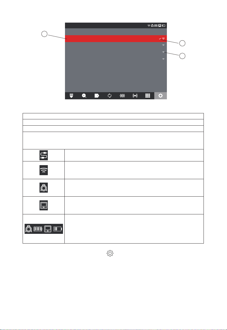
The default connection method for M18™ WIRELESS MONITOR and M18™ 500GB
CONTROL HUB is via WI-FI. The wireless range between the two units is 500'. If an
active CONTROL HUB is within the 500' range, it will show here in the Control Hub List.
As a backup, the WIRELESS MONITOR and CONTROL HUB can be connected by using
a USB-C cable.
First-time WIRELESS MONITOR Paring
• If only one CONTROL HUB is in range, the WIRELESS MONITOR will automatically
force pair with it without any user interaction.
• If there is more than one CONTROL HUB in range, the Control Hub List will appear
on the WIRELESS MONITOR or Milwaukee® Pipeline Inspection App so the user can
choose the desired CONTROL HUB.
20
Page 25
2 M18™ WIRELESS MONITOR
SETTINGS
a
Control Hub List
MTCAM_02938B284
MTCAM_029384BEA
MTCAM_02938ED7A
MTCAM_029383A7E
b
c
Control Hub List
a. List of nearby CONTROL HUBs with active WI-FI
b. Status – checkmark indicates as connected
c. Signal strength of nearby CONTROL HUBs with active WI-FI
Battery Capacity - Both M18™ BATTERY icons have four segments in the icon. Each
segment represents 25% of the battery's power capacity. A low battery warning will
appear when the capacity reaches 10%
Cable Connected icon – Shows the WIRELESS MONITOR and
CONTROL HUB are connected by a USB-C cable.
CONTROL HUB connection status and wireless signal strength.
This icon appears when the CONTROL HUB is connected to the
WIRELESS MONITOR by WI-FI.
PIPELINE INSPECTION REEL icon – appears when the
WIRELESS MONITOR and CONTROL HUB are connected by WIFI or USB-C cable.
WIRELESS MONITOR icon – appears when the WIRELESS
MONITOR and CONTROL HUB are connected by WI-FI or USB-C
cable.
M18™ BATTERY Status icon – two battery icons are shown
separated by the WIRELESS MONITOR icon. The battery icon
to the left of the monitor icon represents the CONTROL HUB.
The battery icon to the right of the monitor icon represents the
WIRELESS MONITOR.
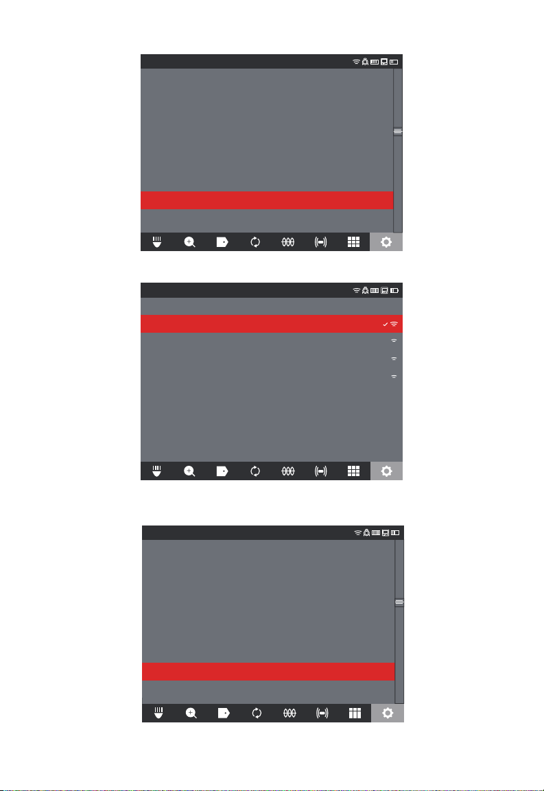
1. Turn the navigation dial to SETTINGS
, press the navigation dial.
2. Turn the navigation dial to CONNECTION SETTINGS, press to enter the sub-menu.
21
Page 26
2 M18™ WIRELESS MONITOR
SETTINGS
MANAGE JOBS
SONDE FREQUENCY
640Hz
LABEL SETTINGS
MANAGE JOBS
2019/05/10 6 FILES
COMPANY NAME
MILWAUKEE
VIDEO SETTINGS
1080P 30FPS
IMAGE SETTINGS
1920x1080
FORMAT DISK
CONNECTION SETTINGS
MTCAM_02938B284
CAMERA SETTINGS
3. Use the navigation dial to choose the desired available CONTROL HUB, press to connect.
SETTINGS
Control Hub List
MTCAM_02938B284
MTCAM_029384BEA
MTCAM_02938ED7A
MTCAM_029383A7E
4. After selecting the CONTROL HUB you will be returned to the main menu. the
CONTROL HUB name is shown in the menu bar under the CONNECTION SETTINGS.
SETTINGS
MANAGE JOBS
SONDE FREQUENCY
640Hz
LABEL SETTINGS
MANAGE JOBS
2019/05/10 6 FILES
COMPANY NAME
MILWAUKEE
VIDEO SETTINGS
1080P 30FPS
IMAGE SETTINGS
1920x1080
FORMAT DISK
CONNECTION SETTINGS
MTCAM_02938B284
CAMERA SETTINGS
22
Page 27
2 M18™ WIRELESS MONITOR
CAMERA LIGHT
9.3FT2019/10/23 01:47:57 AM
CAMERA LIGHT
9.3FT2019/10/23 01:47:57 AM
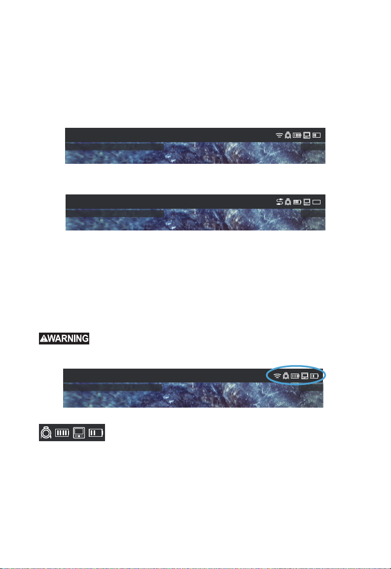
USB-C Cable Connection – The M18™ WIRELESS MONITOR can also be powered
by the M18™ 500GB CONTROL HUB battery via the supplied USB-C cable. This is
extremely useful in some emergency situations in case your battery runs low.
1. With the supplied USB-C cable, plug one end into the CONTROL HUB and the other
into the WIRELESS MONITOR.
2. Conrm the USB-C connection by checking the icons in the status bar on the right.
When connected by USB-C cable the WI-FI icon is now replaced by the cable-connect
icon.
CAMERA LIGHT
The above illustration shows the WIRELESS MONITOR and CONTROL HUB connected
by WI-FI with a weak monitor battery.
CAMERA LIGHT
9.3FT2019/10/23 01:47:57 AM
The above illustration shows the WIRELESS MONITOR and CONTROL HUB connected
by USB-C cable with the M18™ battery removed from the WIRELESS MONITOR. The
WI-FI icon is replaced by the cable-connect icon and the WIRELESS MONITOR battery
shows as empty.
2.2.11 M18™ BATTERY
Both the M18™ WIRELESS MONITOR and M18™ CONTROL HUB are powered by an
M18™ BATTERY. The battery condition of both is always shown in the status bar on the
WIRELESS MONITOR screen.
charging instructions, read the operator's manual supplied with your charger and
Recharge only with the charger specied for the battery. For specic
battery.
CAMERA LIGHT
Battery status – the icon to the left of the WIRELESS MONITOR
icon represents the battery status of the CONTROL HUB while the
icon to the right represents the WIRELESS MONITOR.
23
Page 28
2 M18™ WIRELESS MONITOR
CAMERA LIGHT
2019/10/23 01:47:57 AM 9.3FT
Cancel OK
M18™ 500GB CONTROL HUB – The CONTROL HUB is powered by its M18™
BATTERY which is hot-swappable. If the battery is removed from a running CONTROL
HUB, the below message will appear warning that the CONTROL HUB is operating on
the internal backup battery for a period of nine minutes. During these nine minutes a
charged M18™ BATTERY must be installed, or a USB-C cable must be attached between
the WIRELESS MONITOR and CONTROL HUB. The USB-C cable will now power the
WIRELESS MONITOR temporally.
Typical battery life: M18™ WIRELESS MONITOR: Nine hours on a fully charged battery
M18™ 500GB CONTROL HUB: Nine hours on a fully charged battery
CAMERA LIGHT
Replace Control Hub battery or
Connect Cable to Wireless Monitor
immediately
Time remaining : 08:51
2019_10_23_SCREEN
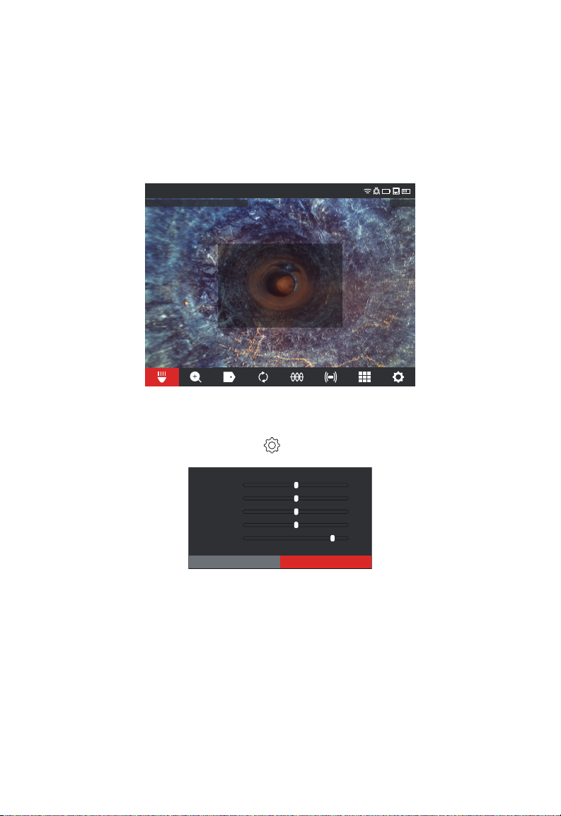
2.2.12 Setting the LCD SCREEN SETTINGS
This setting adjusts the M18™ WIRELESS MONITOR LCD screen settings.
1. Turn the navigation dial to SETTINGS , press the navigation dial.
2. Turn the navigation dial to SCREEN SETTINGS, press to enter the sub-menu.
Hue
Brightness
Contrast
Saturation
Backlight
3. Use the navigation dial to navigate through the menu choices, press the navigation
dial to select one.
4. Turn the navigation dial left and right to adjust the setting, press the navigation dial to
accept it.
5. Scroll to the bottom of the sub-menu and press the navigation dial on OK to accept the
changes.
24
50
50
50
50
8
Page 29
2 M18™ WIRELESS MONITOR
CAMERA LIGHT
2019/10/23 01:47:57 AM 9.3FT
6 7 8
9
18
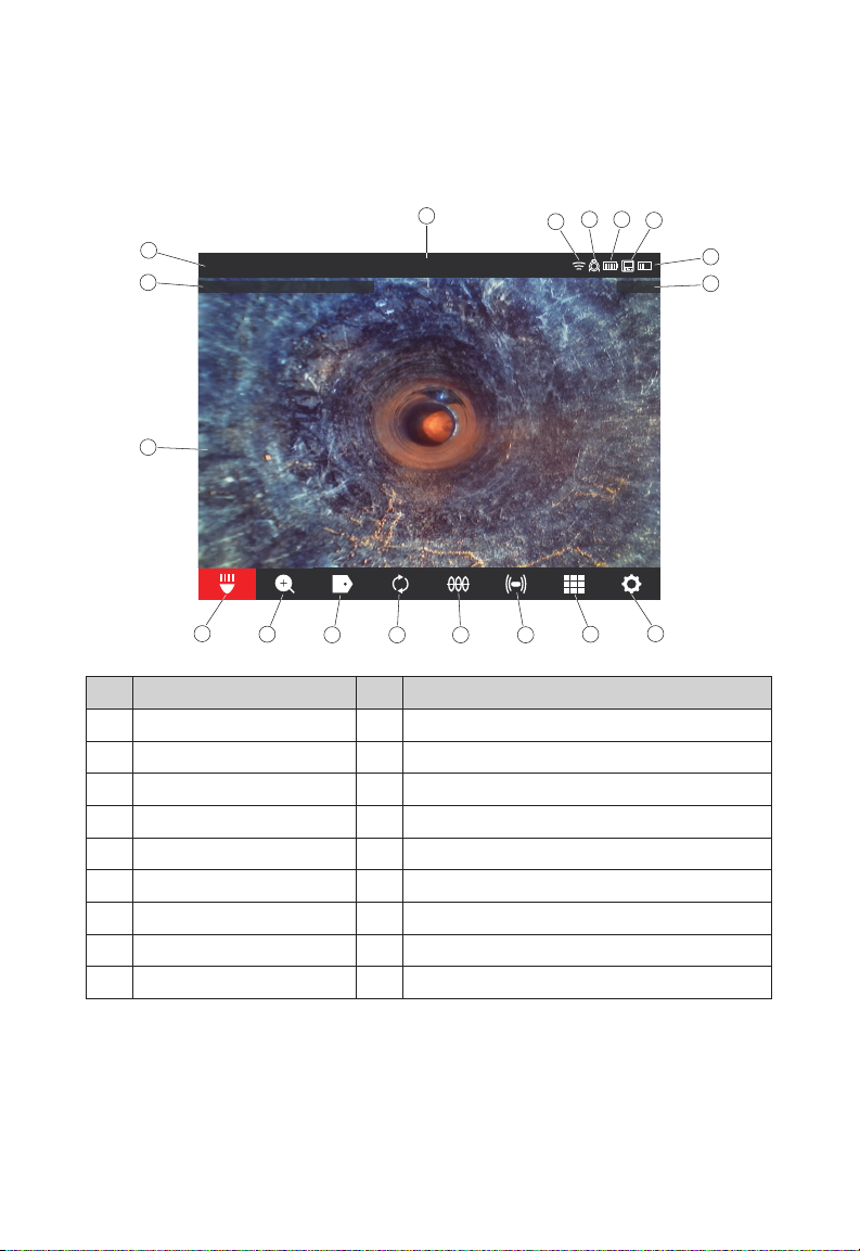
2.3 Using the M18™ WIRELESS MONITOR
Many of these instructions also apply to the Milwaukee® Pipeline Inspection App. The
Milwaukee® Pipeline Inspection App is available for download from the Apple App Store
or at Google Play.
Main Menu Overview
1516
14
13
12
1
2
3
17
CAMERA LIGHT
2019_10_23_SCREEN
4
5
Ref Description Ref Description
1. Status bar 10. GALLERY
2. DATE and TIME stamp 11. SETTINGS menu
3. Main viewing area 12. Distance out count
4. CAMERA LIGHT 13. WIRELESS MONITOR battery status
5. ZOOM & PAN 14. WIRELESS MONITOR connection status icon
6. LABELS 15. CONTROL HUB battery status
7. Screen ROTATE 16. CONTROL HUB connection status icon
8. LINE TRACE 17. WI-FI status
9. SONDE 18. Menu location
1. Status bar – the status bar shows the running options, menu location, connection
status and battery status of both the M18™ 500GB CONTROL HUB and M18™
WIRELESS MONITOR. The status bar is always shown regardless of what mode or
option is being used.
2. DATE & TIME stamp – the DATE & TIME stamps are displayed from the system and
will appear in all recorded videos image les.
25
10
11
Page 30
2 M18™ WIRELESS MONITOR
3. Main viewing area – is the majority of the LCD and shows the raw video from the
camera or videos being played back.
4. CAMERA LIGHT – of the cameras LED's are controlled here.
5. ZOOM & PAN – allows for 4 x zooming with vertical and horizontal panning of the
video feed.
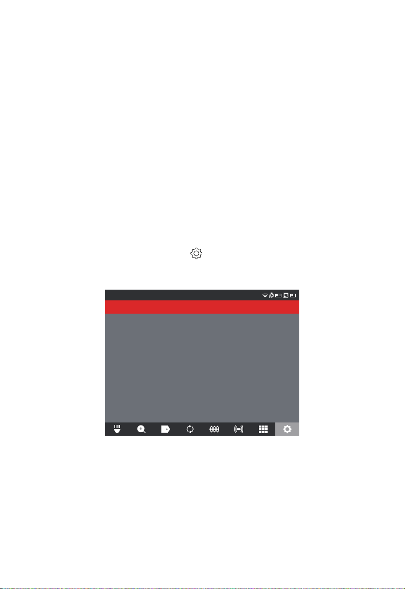
2.3.1 Using JOBS
Before creating a video or image le, you can tell the system where to store the les. This
is known as creating a NEW JOB or CONTINUE EXISTING JOB. Creating a NEW JOB
will setup a container (folder) for both video and image les to be stored in. CONTINUE
EXISTING JOB will route the recordings to a JOB folder that already exists.
The system will automatically ask which JOB to use in certain situations.
1. Whenever the system clock changes to a new day. (after 11:59PM)
2. Whenever the M18™ WIRELESS MONITOR is restarted. (turned off and on again)
3. Whenever the M18™ 500GB CONTROL HUB is restarted. (turned off and on again)
When the Record button is pressed under the above situations, the SELECT JOB List
will appear with options of: NEW JOB WITH DATE AND TIME, NEW JOB WITH NAME or
EXISTING JOB. From this point on the same JOB will be used until changed.
1. Turn the navigation dial to SETTINGS , press the navigation dial.
2. Turn the navigation dial to MANAGE JOBS, press the navigation dial to enter the sub-
menu.
The MANAGE JOBS sub-menu has ve menu options.
SETTINGS
NEW JOB WITH DATE AND TIME
NEW JOB WITH NAME
CONTINUE EXISTING JOB
EXPORT JOB
DELETE JOB
a. NEW JOB WITH DATE AND TIME - Creates a NEW JOB with the systems date
and time as the prex for all les in this folder.
b. NEW JOB WITH NAME - Creates a NEW JOB with the text title entered via the
on-screen keyboard.
c. CONTINUE EXISTING JOB – Send the new les to an EXISTING JOB previously
created.
d. EXPORT JOB – Copies the JOB from the CONTROL HUB INTERNAL DRIVE to
a CONTROL HUB THUMB DRIVE.
e. DELETE JOB – Deletes the JOB from the CONTROL HUB INTERNAL DRIVE.
26
Page 31
2 M18™ WIRELESS MONITOR
3. Use the navigation dial to navigate the menu choices. Press the navigation dial to
enter the desired sub-menu.
4. Scroll to the bottom of the sub-menu and press the navigation dial on OK to accept the
nal changes.
The changes will be saved into memory, and the system will return to the main viewing
screen.
Creating a NEW JOB
1. From the JOB's sub-menu use the navigation dial to select NEW JOB WITH DATE
AND TIME or NEW JOB WITH NAME.
If NEW JOB WITH DATE AND TIME is selected a JOB folder with the system current
date and time will be created and named YYYY_MM_DD_HH_MM_SS.
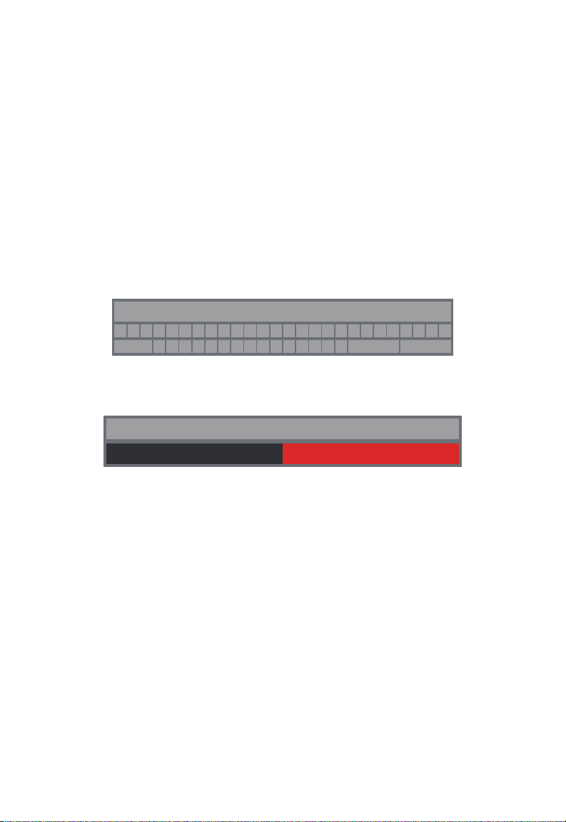
If a NEW JOB WITH NAME is selected, the next screen will be the on-screen
keyboard.
MT2019_A
A B C D E F G H I J K L M N O P Q R S T U VWX Y Z
-
SPACE
1 2 3 4 5 6 7 8 9 0
. ,
? !
DELETE
ENTER
2. Use the navigation dial to enter the name of the NEW JOB WITH NAME.
3. When nished entering the new job name use the navigation dial to ENTER and press
the dial.
MT2019_A
CANCEL SAVE
4. Use the navigation dial to select SAVE and press the navigation dial.
When a NEW JOB WITH NAME is selected a JOB folder with the system current date
and time will be used as a prex. The folder created and named YYYY_MM_DD_NEW
JOB NAME.
2.3.2 Creating a Video Recording and Image Capturing
By default, all videos and images recorded are saved to the M18™ 500 GB CONTROL
HUB INTERNAL DRIVE. If a thumb drive is plugged into the CONTROL HUB, all videos
and pictures can be saved to both the CONTROL HUB INTERNAL DRIVE and CONTROL
HUB THUMB DRIVE.
Filenames – the le names are automatically created by the system and consist of the
year, month, day, time created, and or JOB name. This will vary depending on the JOB
type selected.
If selecting NEW JOB WITH DATE AND TIME, the filename will look like this:
2019_10_01_12_50_10_2
2019 = Year, _10 = Month, _01 = Day, _12 = Hour, _50 = Minutes, _10 = Seconds and _2
= second le created.
27
Page 32

2 M18™ WIRELESS MONITOR
CAMERA LIGHT
2019/10/23 01:47:57 AM 9.3FT
CAMERA LIGHT
2019/10/23 01:47:57 AM 9.3FT
If selecting NEW JOB WITH NAME, the filename will look like this: 2019_10_01_
JOBNAME_1
2019 = Year, _10 = Month, _01 = Day, _JOBNAME and_3 = third le created.
If a le were saved as a Highlight video, the lename would be followed by "_h".
1. Press the Record button on the M18™ WIRELESS MONITOR to start the
recording. If this is the first recording of the day or if the WIRELESS MONITOR or
CONTROL HUB was restarted, when the record button is pressed the SELECT JOB
dialog box will appear to route the recording record to the appropriate JOB folder.
SETTINGS
SELECT JOB
NEW JOB WITH DATE AND TIME
NEW JOB WITH NAME
EXISTING JOB
CANCEL
No job selected
2. Choose the desired option and press the navigation dial.
3. After the JOB option has been selected, a ashing recording icon will appear in the
upper left corner of the status bar with the video recording length in minutes and
seconds.
00:05
SETTINGS
2019_10_23_SCREEN
Recording icon and video length
Image Files – images can be captured while recording or viewing raw video from the
camera. The image will be saved in the same JOB folder as the video.
28
Page 33
2 M18™ WIRELESS MONITOR
4. Press the PICTURE button to capture an image. The screen will ash red for a
moment conrming that the image was captured.
At the end of the session, press the RECORD button again to end and save the
video le.
2.3.3 EXPORT JOB
The EXPORT JOB allows for the copying of les from the M18™ 500GB CONTROL HUB
INTERNAL DRIVE to the CONTROL HUB THUMB DRIVE.
From within the GALLERY individual les can be exported one at a time.
From the MANAGE JOBS option, under SETTINGS entire folders of JOBS can be
EXPORTED in one session.
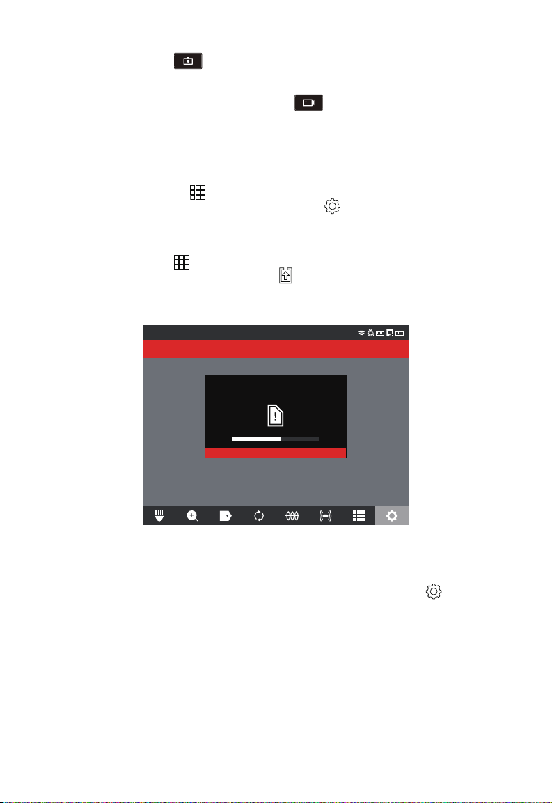
EXPORT JOB from the GALLERY
1. From the GALLERY select the desired video or image.
2. Use the navigation dial to select EXPORT , press the dial.
3. Use the navigation dial to select the export destination of CONTROL HUB THUMB
DRIVE, press the navigation dial. The progress indicator will appear showing the
status.
CONTROL HUB THUMB DRIVE
3.942GB/29.817GB
Saving “PROJECTNAME”.
SETTINGS
CANCEL
4. Wait for the progress indicator to run until completed.
EXPORT JOB from within the SETTINGS menu
1. From the main viewing screen, turn the navigation dial to SETTINGS , press the
navigation dial.
2. Turn the navigation dial to MANAGE JOBS, press the navigation dial.
3. Turn the navigation dial to EXPORT JOB, press the navigation dial.
4. Turn the navigation dial to select the JOB to export, press the navigation dial. The
export destination of CONTROL HUB THUMB DRIVE appears.
5. Press the navigation dial. The progress indicator will show the status.
29
Page 34
2 M18™ WIRELESS MONITOR
CAMERA LIGHT
2019/10/23 01:47:57 AM 9.3FT
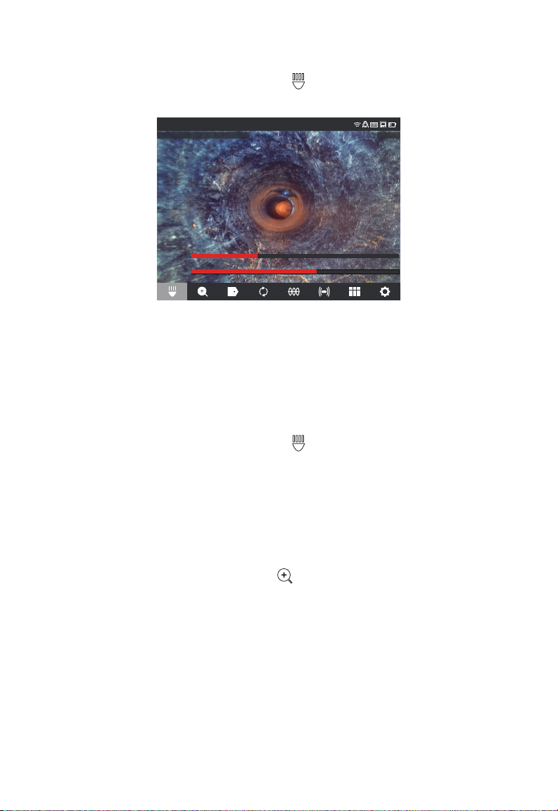
2.3.4 Adjusting the CAMERA LIGHT
1. Turn the navigation dial to CAMERA LIGHT , press the navigation dial.
2. Turn the navigation dial to reach the desired light level.
3. Pressing the navigation dial again will select the IMAGE ENHANCE option.
CAMERA LIGHT
LIGHT
LEVEL
IMAGE
ENHANCE
The LIGHT LEVEL and IMAGE ENHANCE level
4. Press the BACK button to exit and return to the main viewing area.
2.3.5 IMAGE ENHANCE
The IMAGE ENHANCE feature allows the LCD display to show more detail and depth
from the camera head in different textures and colors of pipes. The IMAGE ENHANCE
feature automatically adjust the LCD's display brightness and contrast settings based on
the light from the camera head.
1. Turn the navigation dial to CAMERA LIGHT , press the navigation dial.
2. Turn the navigation dial to reach the desired light level.
3. Press the navigation dial to move to IMAGE ENHANCE.
4. Use the navigation dial to move the IMAGE ENHANCE scale stopping on the best
result.
Press the navigation dial to accept the setting.
5. Press the BACK button to exit and return to the main viewing area.
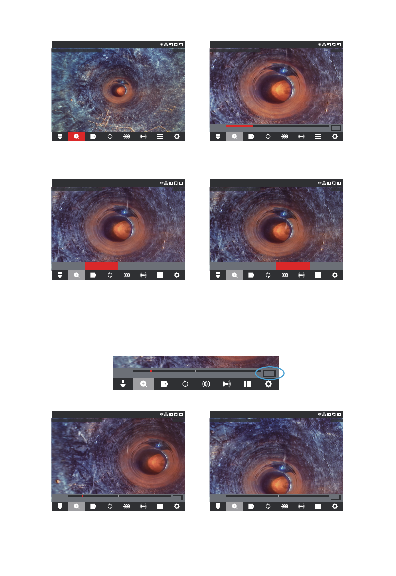
2.3.6 ZOOM & PAN
1. Turn the navigation dial to ZOOM & PAN , press the navigation dial.
2. ZOOM - Turn the navigation dial to ZOOM, press the navigation dial.
3. Turn the navigation dial to reach one of four ZOOM levels and press the navigation
dial. Turn the navigation dial to ZOOM in or out, the graphic to the far right will grow or
shrink according to the ZOOM level.
4. Press the navigation dial.
30
Page 35
2 M18™ WIRELESS MONITOR
CAMERA LIGHT
2019/10/23 01:47:57 AM 9.3FT
CAMERA LIGHT
2019/10/23 01:47:57 AM 9.3FT
CAMERA LIGHT
2019/10/23 01:47:57 AM 9.3FT
CAMERA LIGHT
2019/10/23 01:47:57 AM 9.3FT
CAMERA LIGHT
2019/10/23 01:47:57 AM 9.3FT
CAMERA LIGHT
2019/10/23 01:47:57 AM 9.3FT
2019_10_23_SCREEN
ZOOM & PAN
2019_10_23_SCREEN
ZOOM
Min Max
ZOOM & PAN
2x
Standard ZOOM ZOOM X 2
5. PAN - Turn the navigation dial to HORIZ or VERT and press the navigation dial.
ZOOM & PAN
2019_10_23_SCREEN
ZOOM HORIZ VERT EXIT
2019_10_23_SCREEN
ZOOM HORIZ VERT EXIT
ZOOM & PAN
Select HORIZ or VERT and press the navigation dial
PAN Horizontal and Vertical – Panning horizontally moves the position in the image
in right and left directions. Panning vertically moves the position in the image in up and
down directions. In both options as the navigation dial is turned in PAN HORIZ or PAN
VERT, the graphic to the far right on will move with the vertical or horizontal panning
showing where you are located within the image.
PAN
2019_10_23_SCREEN
HORIZ
ZOOM & PAN
PAN
2019_10_23_SCREEN
Left Right
HORIZ
Example of PANNING HORIZ, to the left Example of PANNING VERT, up
Left Right
Pan location reference
PAN
2019_10_23_SCREEN
Up Down
VERT
31
ZOOM & PAN
Page 36
2 M18™ WIRELESS MONITOR
CAMERA LIGHT
2019/10/23 01:47:57 AM 9.3FT
CAMERA LIGHT
2019/10/23 01:47:57 AM 9.3FT
2019/10/23 01:47:57 AM 9.3FT
6. Press the BACK button to exit and return to the main viewing area.
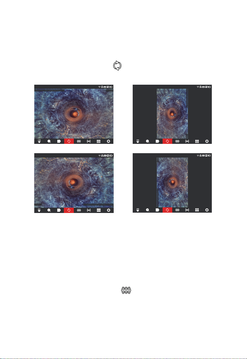
2.3.7 Screen ROTATE
Screen ROTATE – will invert the upright picture 90° with each push of the navigation dial.
This is helpful while using the reel in the horizontal position, and the monitor may not be
in an upright position.
1. Turn the navigation dial to ROTATE
ROTATE option.
2. With each press of the navigation dial, the screen will ROTATE 90° to the right.
ROTATE
, press the navigation dial to start the screen
ROTATE
2019_10_23_SCREEN
0 Degrees (default) 90 Degree position
ROTATE
2019_10_23_SCREEN
180-degree position 270-degree position
Note: The screen will remain in a ROTATE position until it is adjusted back to the default
in this setting.
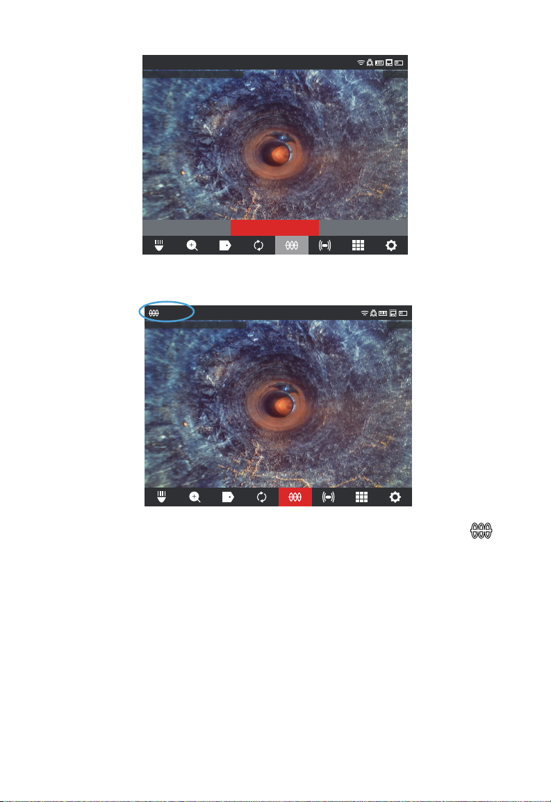
2.3.8 LINE TRACE
LINE TRACE – activates the internal transmitter to inject a locate signal onto the
push cable. The length of deployed push cable can now be located and traced above
ground with a locator set to the matching LINE TRACE frequency. The M18™ 500GB
CONYTROL HUB must be properly grounded when using the LINE TRACE feature. See
section 3.3.3 in this manual covering the Grounding Post for additional information.
1. Turn the navigation dial to LINE TRACE
2. Turn the navigation dial to select a LINE TRACE frequency of 33kHz or 83kHz and
press the navigation dial.
2019_10_23_SCREEN
2019/10/23 01:47:57 AM 9.3FT
2019_10_23_SCREEN
, press the navigation dial.
ROTATE
32
Page 37
2 M18™ WIRELESS MONITOR
CAMERA LIGHT
2019/10/23 01:47:57 AM 9.3FT
CAMERA LIGHT
2019/10/23 01:47:57 AM 9.3FT
LINE TRACE
2019_10_23_SCREEN
OFF 33kHz 83kHz
The LINE TRACE is now active, and the LINE TRACE icon with selected frequency will
appear in the status bar.
33kHZ
LINE TRACE
2019_10_23_SCREEN
3. Deactivate the LINE TRACE mode by turning the navigation dial to LINE TRACE ,
press the navigation dial and select OFF, and press.
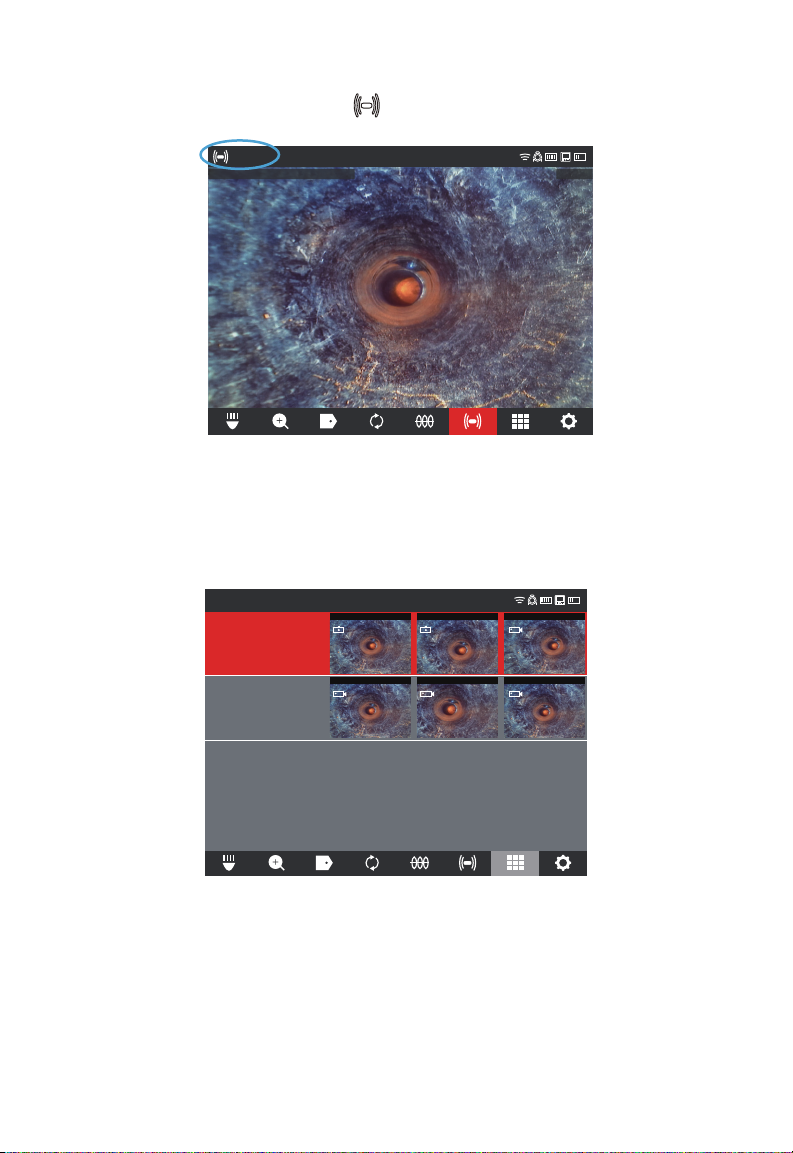
2.3.9 SONDE
SONDE - activates the SONDE transmitter attached at the end of the PIPELINE
INSPECTION REEL termination spring to locate the approximate position of the SONDE
in the pipe. The choice of the SONDE frequency was selected during setup and can
be changed by going to SETTINGS, and then SONDE FREQUENCY. The choices of
SONDE frequencies to use are 33kHz, 512Hz or 640Hz.
33kHz – is useable in non-metallic pipes.
512Hz – is mostly used in North America and is useable in both metallic and non-metallic
pipes
640Hz – is mostly used in Europe and is useable in both metallic and non-metallic pipes
33
Page 38
2 M18™ WIRELESS MONITOR
CAMERA LIGHT
2019/10/23 01:47:57 AM 9.3FT
a. Turn the navigation dial to SONDE and press the dial. The SONDE is now active,
and the SONDE icon will appear in the status bar along with the frequency.
640Hz
2019_10_23_SCREEN
SONDE
b. To deactivate the SONDE press the navigation dial when it shows the SONDE icon
selected.
2.3.10 GALLERY Overview
In the GALLERY, all the videos and pictures are shown organized in folders and stored
for reviewing, editing, exporting or deleting.
GALLERY
2019_10_23
Stored Location:internal disk
23/10/2019 ARCHIVOS:6
2019_10_21
Stored Location:thumb drive
21/10/2019 ARCHIVOS:3
201910230518c 201910230518b 201910230518a
00:18
201910211052c 201910211052b 201910211052a
00:19
2019/10/21
02:05
2019/10/21
2019/10/232019/10/23 2019/10/23
01:02
2019/10/21
In the GALLERY view, each JOB folder is shown with the date and number of les in the job.
The Saved Locations labels GALLERY show if the les are located on the CONTROL HUB
INTERNAL DRIVE or CONTROL HUB THUMB DRIVE.
34
Page 39
2 M18™ WIRELESS MONITOR
2019_10_23
201910230518c 201910230518b 201910230518a 201910230516b_h
GALLERY
2019/10/23
201910230516a 201910230515a
01:20
2019/10/232019/10/23
00:18
2019/10/232019/10/23
00:20
2019/10/23
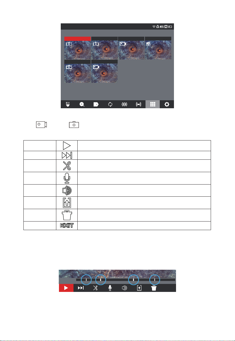
When entering the job folder, the individual les are shown with thumbnails showing the
video or picture icon.
Options for les in the gallery include:
PLAY
RW/FF
TRIM
RECORD
AUDIO
SPEAKER
VOLUME
EXPORT
DELETE
EXIT
Plays back a recorded video le or views a jpg picture le
Rewind and fast forward
Edits the video length by selecting portions of the video to
keep and portions trim
Add audio comments on top of video les
Adjust the playback volume of video les
Copies the les from the CONTROL HUB Internal Drive to the
CONTROL HUB THUMB DRIVE or mobile device
Deletes the le(s) from the CONTROL HUB INTERNAL DRIVE
or CONTROL HUB THUMB DRIVE
Exits the GALLERY menu and returns to the JOB folder
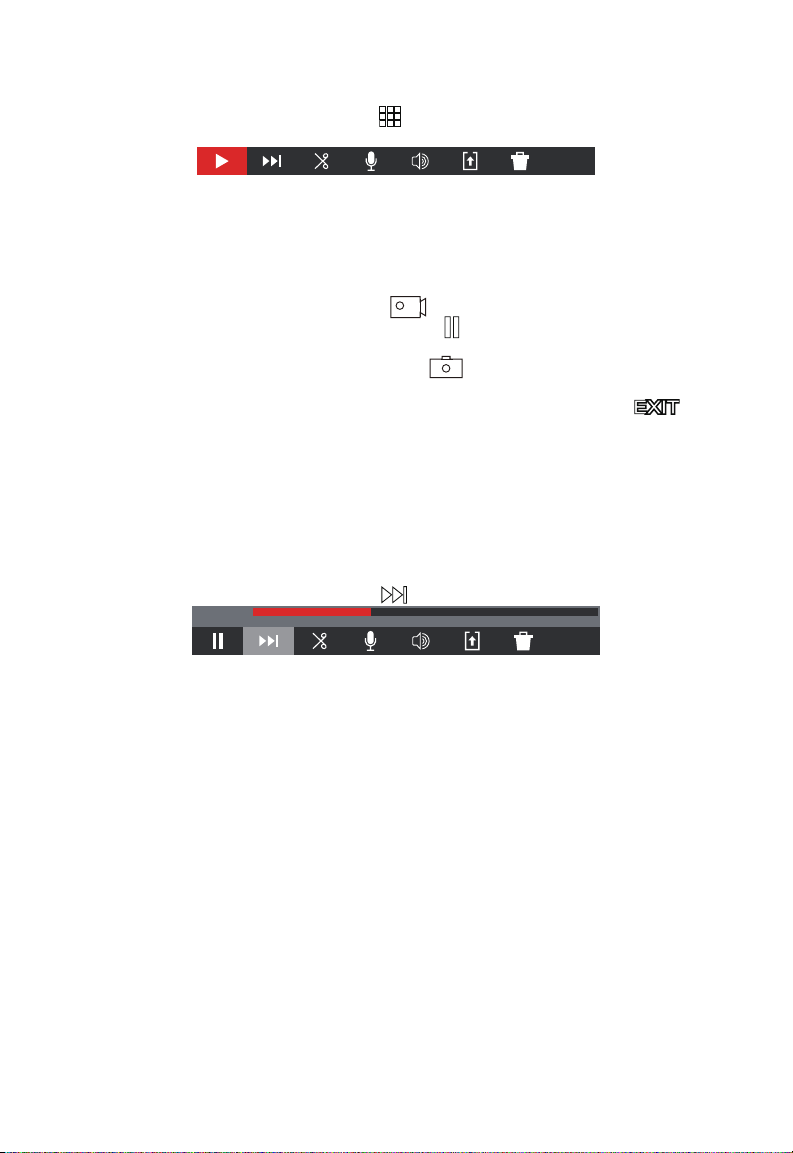
2.3.11 Playback Highlights
When LABELS (section 2.3.18) or audio comments (section 2.3.15) are added to
recording videos via the internal microphone, these parts of the video where the label or
audio was added are marked with a highlight marker in the video playback progress bar.
These highlight markers are shown with a white bar in the playback progress bar.
PLAYBACK
2019_10_23_SCREEN
The progress bar with highlights shown
This is extremely useful while reviewing videos as it shows a place of interest of comment
in the video to fast forward or rewind to.
35
00:00 / 00:40
EXIT
Page 40
2 M18™ WIRELESS MONITOR
00:00 / 00:40
2019_10_23_SCREEN
PLAYBACK
2.3.12 Playing videos and viewing pictures
1. Turn the navigation dial to GALLERY , press the navigation dial to view the sub-
menu.
EXIT
Gallery sub-menu
2. Turn the navigation dial to the folder whose files are to be accessed, press the
navigation dial.
3. Turn the navigation dial to select a le, press the navigation dial.
Play a video le – Select the video le
using the navigation dial, press the dial
to start the playback. Use the pause function to pause and resume playing the
video le.
Viewing a picture le – Select the picture le using the navigation dial and press
the navigation dial to view the picture.
4. When nished viewing the video or picture, rotate the navigation dial to and
press the navigation dial to return to the folders sub-menu. Use the back key to return
to the main viewing screen.
2.3.13 Rewind and Fast Forward
Use the rewind and fast forward feature to move through a playing video.
1. From the GALLERY use the navigation dial to select a video to play, press the
navigation dial.
2. Select the RW/FF (rewind/fast forward)
3. Turn the navigation dial clockwise to fast forward or counterclockwise to rewind. While
turning the navigation dial, the red bar progress indicator shows the place in the video
recording. Each turn of the navigation dial advances or rewinds the video.
4. Press the navigation dial again to return to the sub-menu, scroll to EXIT and press the
navigation dial to exit to the GALLERY.
menu option and press the navigation dial.
00:14 / 00:40
EXIT
36
Page 41
2 M18™ WIRELESS MONITOR
CAMERA LIGHT
2019/10/23 01:47:57 AM 9.3FT
CAMERA LIGHT
2019/10/23 01:47:57 AM 9.3FT
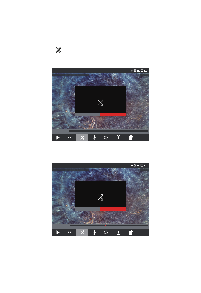
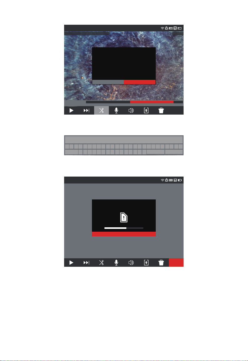
2.3.14 Trimming Video Files
Use the TRIM feature to edit the length of a video and save it as a new le.
1. From the JOB folder in the GALLERY use the navigation dial to select the video le to
TRIM, press the navigation dial.
2. Select the TRIM menu option and press the navigation dial.
3. Press CONTINUE at the "Set desired beginning of clip message". Turn the
navigation dial clockwise while watching the advancement of the video to select the
TRIM starting point, press the navigation dial.
TRIM
Set desired beginning of clip.
CANCEL CONTINUE
TRIM
2019_10_23_SCREEN
4. Press CONTINUE at the "Set desired end of clip" message. Turn the navigation dial
counterclockwise while watching the advancement of the video to select the TRIM
ending, press the navigation dial.
TRIM
00:00 / 00:40
EXIT
Set desired end of clip.
CANCEL CONTINUE
TRIM
2019_10_23_SCREEN
5. Press TRIM at the "Conrm trim" message, this will create a new trimmed video.
00:18 / 00:40
EXIT
37
Page 42
2 M18™ WIRELESS MONITOR
CAMERA LIGHT
2019/10/23 01:47:57 AM 9.3FT
TRIM
Confirm trim? This will create a new file.
CANCEL TRIM
TRIM
2019_10_23_SCREEN
00:18 / 00:36
EXIT
6. Use the on-screen keyboard to enter the new le name, when nished with the new
le name navigate to ENTER and press the navigation dial.
A B C D E F G H I J K L M N O P Q R S T U VWX Y Z
SPACE
1 2 3 4 5 6 7 8 9 0
201905100515a0101
. ,
-
? !
DELETE
ENTER
7. Now select SAVE to save the new trimmed le. A dialog box will appear showing the
le saving progress.
SAVE & EXIT
Saving “20190510051501.mp4” to
CONTROL HUB Internal Drive.
8. The new trimmed le is now placed in the same JOB folder as the original le.
CANCEL
EXIT
38
Page 43

2 M18™ WIRELESS MONITOR
2.3.15 Recording Audio
This feature adds audio comments to recording videos or to existing videos already in
the gallery. This is useful to add audio annotations to accompany any labels used in
the video or if something new was spotted during the review of the video. When adding
annotations to an existing video le, the original le will remain the same, and a new le
will be created with the annotations. You will have to name this new le at the end of the
procedure.
Note that any HIGHLIGHTS from the original video will not be saved in the newly created
video you are adding an audio comment to.
1. From the GALLERY select the desired video to add annotations to.
2. Select PLAY
Use the RW/FF
3. Turn the navigation dial to the RECORD AUDIO
activate the microphone. Note that the Microphone Button will glow red when active.
4. Speak clearly facing the internal microphone (located in the top left corner of the
M18™ WIRELESS MONITOR) and be in the range of 48 inches from it.
5. Press the navigation dial again (which is currently on Microphone) to deactivate the
microphone.
6. Turn the navigation dial to select SAVE & EXIT, press the navigation dial.
7. Select OK on the message to set a name for the new annotated le.
8. Use the on-screen keyboard to enter a name for the file, navigate to and select
RETURN, then select SAVE.
9. Wait for the progress indicator to run until completed.
to watch the video, press PAUSE at the spot to add the annotation.
feature to reach highlighted parts of the video.
icon and press navigation dial to
2.3.16 Speaker Volume
The SPEAKER VOLUME can be adjusted during video playback and while editing videos.
1. From the GALLERY select the desired video.
2. Use the navigation dial to select SPEAKER VOLUME
3. Use the navigation dial to set the SPEAKER VOLUME, then press the navigation dial
and the system will return to the video sub-menu.
, press the navigation dial.
2.3.17 Delete Files
From within the GALLERY individual les can be deleted one at a time.
From the SETTINGS menu, select MANAGE JOBS and entire folders of jobs can
be deleted in one session.
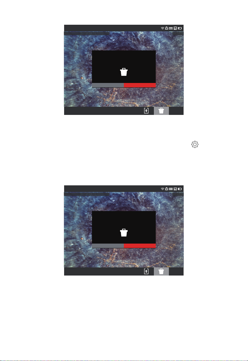
Deleting les from the Gallery
1. From the GALLERY select the desired JOB folder, then desired video folder from
within the JOB.
2. Use the navigation dial to select DELETE , press the navigation dial.
3. Acknowledge the deletion pop up message by pressing the navigation dial when
DELETE is selected.
39
Page 44
2 M18™ WIRELESS MONITOR
CAMERA LIGHT
2019/10/23 01:47:57 AM 9.3FT
CAMERA LIGHT
2019/10/23 01:47:57 AM 9.3FT
DELETE
Are you sure you want to delete the file:
“201910230518c.jpg”
CANCEL DELETE
2019_10_23_SCREEN
EXIT
The le has been deleted, and the system returns to the gallery sub-menu.
Deleting Files from within the SETTINGS menu
1. From the main viewing screen, turn the navigation dial to SETTINGS , press the
navigation dial.
2. Turn the navigation dial to MANAGE JOBS, press the navigation dial.
3. Turn the navigation dial to DELETE JOB, press the navigation dial.
4. Turn the navigation dial to select the JOB to delete, press the navigation dial.
5. Acknowledge the deletion pop up message by pressing the navigation dial when
DELETE is selected.
DELETE
Are you sure you want to delete the file:
“201910230518c.jpg”
CANCEL DELETE
2019_10_23_SCREEN
The JOB folder and files within it have been deleted, and the system returns to the
MANAGE JOBS sub-menu. Press the Back key to exit the sub-menu, press again to
return to the main viewing screen.
EXIT
40
Page 45
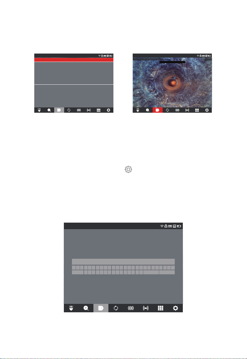
2 M18™ WIRELESS MONITOR
CAMERA LIGHT
2019/10/23 01:47:57 AM 9.3FT
2.3.18 Using LABELS
LABELS are predefined observations that are splashed on the screen and appear in
recorded videos and captured pictures. When a LABEL is selected, it will appear on the
screen for 15-seconds and then disappear.
ADD CUSTOM
FREQUENTLY USED
BELLIED PIPE
CONNECTING PIPE
CRACKED PIPE
OFFSET JOINT/MISALIGNED
ROOTS
TEE
ALL LABELS
BELLIED PIPE
CONNECTING PIPE
CRACKED PIPE
OFFSET JOINT/MISALIGNED
ROOTS
TEE
LABELS
2019_10_23_SCREEN
List of created LABELS The LABEL shown splashed on the screen
In the LABELS sub-menu, the option of ADD CUSTOM allows the creation of a new label.
Also shown on the screen is the list of FREQUENTLY USED and ALL LABELS.
After a label is used more than ve times, it will automatically be added to the Frequently
Used list of labels.
Creating and saving a new label
1. Turn the navigation dial to the SETTINGS
option, press the navigation dial to enter
the SETTINGS sub-menu.
2. Turn the navigation dial to the LABEL SETTINGS option, press the navigation dial to
enter the sub-menu.
3. Select ADD CUSTOM and press the navigation dial.
4. Use the navigation dial to navigate the on-screen keyboard pressing the navigation
dial to accept each keyboard character.
5. When finished with the label, navigate to the ENTER key and press the navigation
dial.
LABEL
LABEL
BELLIED PIPE
A B C D E F G H I J K L M N O P Q R S T U VWX Y Z
SPACE
6. Select SAVE or CANCEL to the conrmation message and press the navigation dial to
continue.
BELLIED PIPE
1 2 3 4 5 6 7 8 9 0
41
-
. ,
? !
DELETE
ENTER
Page 46
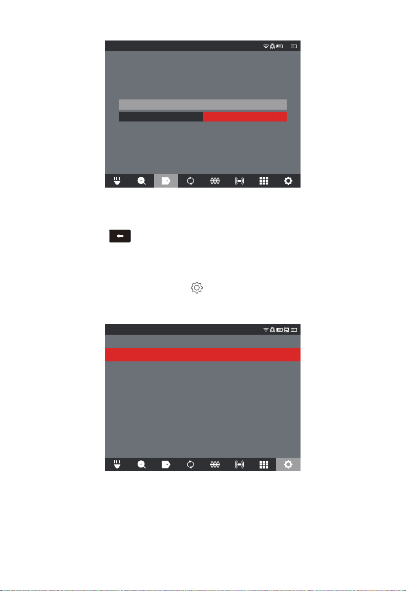
2 M18™ WIRELESS MONITOR
LABEL
BELLIED PIPE
CANCEL SAVE
The label now appears in the ALL LABELS list and is available to use with the LABELS
option from the main viewing screen.
7. Press the Back key to return to the LABELS sub-menu, press again to return to
the main viewing screen.
Editing labels
Previously created LABELS can be edited or deleted with this option.
1. Turn the navigation dial to SETTINGS , press the navigation dial.
2. Turn the navigation dial to LABEL SETTINGS, press the navigation dial to enter the
sub-menu.
3. Select EDIT LABELS and press the navigation dial.
SETTINGS
RESET FREQUENTLY USED LABELS LIST
EDIT LABELS
4. Use the navigation dial to navigate to and select the label for editing or deletion, press
the navigation dial.
5. Select EDIT or DELETE and press the navigation dial.
42
Page 47
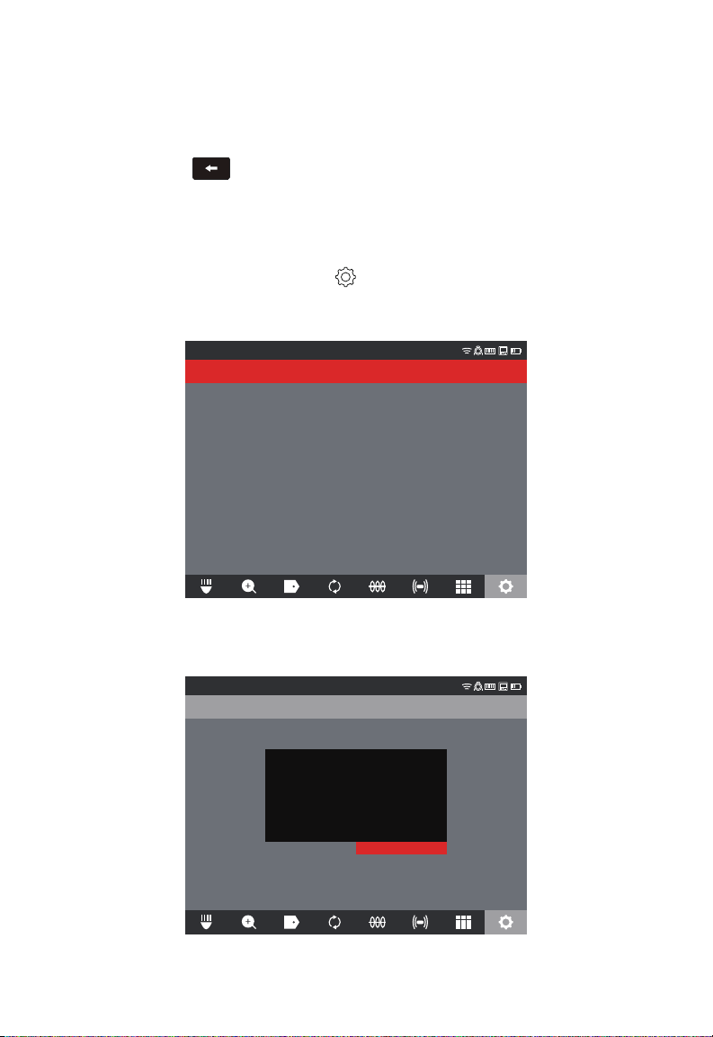
2 M18™ WIRELESS MONITOR
Editing – will bring up the on-screen keyboard, make the edits and navigate to the
ENTER key, press the navigation dial, then select SAVE to save the label changes.
Follow the instructions under "Creating and saving a new label" to edit and save.
Delete – Will delete the label from memory.
6. Press the Back
key to return to the LABELS sub-menu, press again to return to
the main viewing screen.
Reset the FREQUENTLY USED LABEL LIST
This will remove previously used labels currently in the FREQUENTLY USED LABEL
LIST.
1. Turn the navigation dial to SETTINGS , press the navigation dial.
2. Turn the navigation dial to the LABEL SETTINGS option, press the navigation dial to
enter the sub-menu.
3. Select RESET FREQUENTLY USED LABEL LIST and press the navigation dial.
SETTINGS
RESET FREQUENTLY USED LABELS LIST
EDIT LABELS
4. Acknowledge the on-screen message by pressing the navigation dial again or turn the
navigation dial to select Cancel.
SETTINGS
RESET FREQUENTLY USED LABELS LIST
EDIT LABELS
Do you want to reset the frequently used
label list?
Cancel OK
43
Page 48
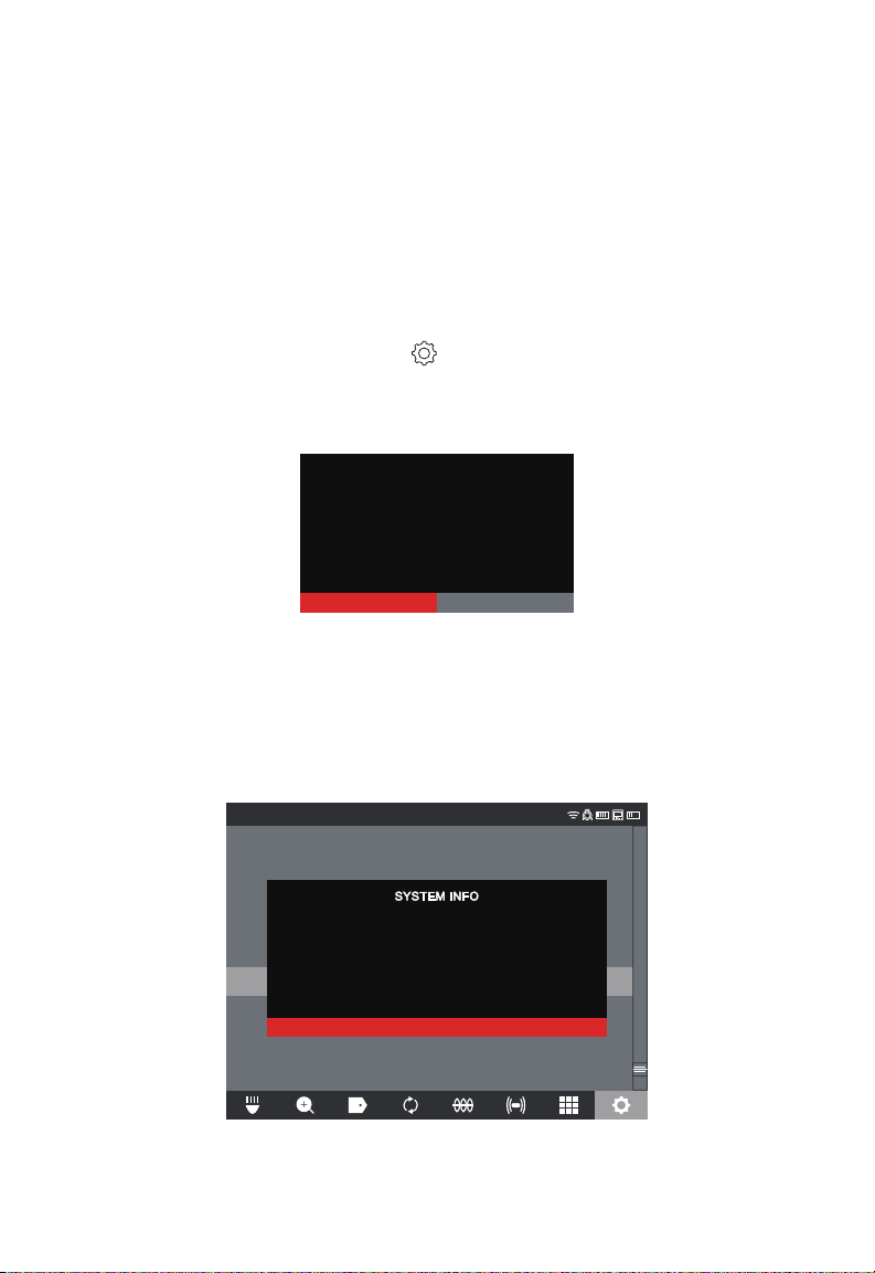
2 M18™ WIRELESS MONITOR
Cancel OK
2.4 Factory Reset & Firmware Updates – M18™ WIRELESS
MONITOR
2.4.1 Factory Reset – M18™ WIRELESS MONITOR
Performing a factory reset will reset the M18™ WIRELESS MONITOR to the factory
defaults. On the WIRELESS MONITOR, the functionality that will reset to the factory
default will be:
• Backlight settings back to default
• WIRELESS MONITOR/CONTROL HUB connection settings
• System language
1. Turn the navigation dial to SETTINGS , press the navigation dial.
2. Turn the navigation dial to FACTORY RESET, press the navigation dial to enter the
sub-menu.
3. Select FACTORY RESET WIRELESS MONITOR and press the navigation dial.
4. Read and acknowledge the factory reset message by selecting OK.
Do you want to factory reset the Wireless
Monitor?
The factory reset is now complete, and the system is returned to the FACTORY RESET
sub-menu.
2.4.2 Firmware Updates – M18™ WIRELESS MONITOR
Before updating a system, go to the ABOUT section (found at the bottom of the
SETTINGS menu) of the SETTINGS menu and make a note of the current rmware
revisions in the system.
SETTINGS
DATE & TIME
UNITS
Feet
LANGUAGE
English
MANAGE JOBS
2019/05/10 6 FILES
SYSTEM UPGRADE
WIRELESS MONITOR SERIAL NUMBER:
WIRELESS MONITOR FIRMWARE VERSION:
FACTORY RESET
CONTROL HUB SERIAL NUMBER:
ABOUT
CONTROL HUB FIRMWARE VERSION:
SERVICE & SUPPORT
DISMISS
System information is shown in the About screen
44
1029384756
1.0.0.1106
102938ED3B
1.0.0.1106
Page 49

2 M18™ WIRELESS MONITOR
CANCEL OK
OK
1. Insert the USB stick containing the firmware update into the M18™ WIRELESS
MONITOR's USB port.
2. Turn the navigation dial to SETTINGS , press the navigation dial.
3. Turn the navigation dial to the SYSTEM UPDATE option, press the navigation dial to
enter the sub-menu.
4. Select WIRELESS MONITOR and press the navigation dial. The filename of the
update should be seen in this window.
Press the navigation dial when the update le is highlighted in red to begin the update.
SETTINGS
MTCam_monitor.bin
Update les end with a .bin le extension
5. Read and acknowledge the warning message by selecting OK.
Selecting OK will run a firmware update in
the Wireless Monitor. Please do not interrupt
the update process after it has started.
6. A progress indicator will appear showing the progress of the update.
The Wireless Monitor is updating...
58%
7. A conrmation message will appear when the update is complete, and the system will
reboot.
The Wireless Monitor will now restart in order to
complete the firmware update.
8. Go to the ABOUT option in the SETTINGS menu to conrm that the rmware revision
numbers have updated.
45
Page 50
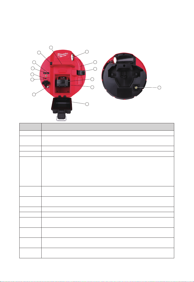
3 M18™ 500GB CONTROL HUB
3. M18™ 500GB CONTROL HUB
3.1 Overview
1
2
12
3
4
5a
5b
6
11
10
9
8
7
Reference Description
1. Handle
CONTROL HUB lock release button – push to unlock the CONTROL HUB
2.
assembly from the PIPELINE INSPECTION REELs
3. Power button - Press to turn on, press and hold to turn off
4. Distance reset button – resets the distance of deployed push cable to Zero
USB compartment cover – is a watertight cover to keep debris out of the
compartment.
5a USB-A port - for direct saving of videos and pictures and to perform
5.
rmware updates.
5b USB-C port – optional for supplying power and data between the
WIRELESS MONITOR and CONTROL HUB.
Grounding post – to ground the CONTROL HUB to earth while tracing push
6.
cable
Battery compartment cover - is a watertight cover to keep debris out of the
7.
compartment
8. Battery compartment – for M18™ BATTERY
9. M18™ BATTERY
Spring locking clip - holds the spring and camera in place during
10.
transportation
Spring recess – keeps the spring and camera in place during transportation
11.
and storage.
Cable guide – feed the spring and push cable through the guide before
12.
locking the CONTROL HUB in place
Camera test port – is a troubleshooting tool for isolating the camera head's
13.
performance
13
46
Page 51
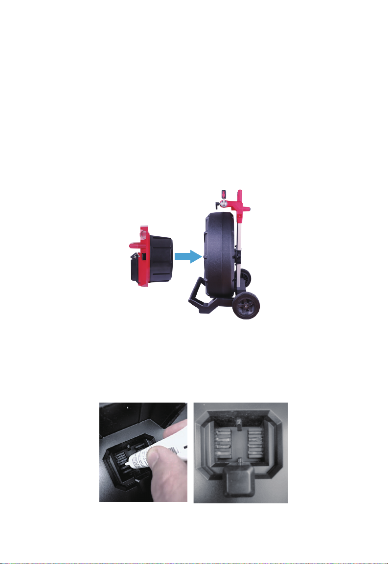
3 M18™ 500GB CONTROL HUB
3.2 Installing and removing the M18™ 500GB CONTROL
HUB
Installing the M18™ 500GB CONTROL HUB
1. Grasp the CONTROL HUB by the handle and present it to the PIPELINE INSPECTION
REEL.
2. On the back of the reel, turn the push cable drum brake locking knob counterclockwise
to unlock it.
3. Reach into the reel and grab the spring termination assembly.
4. Feed the spring and one foot of push cable through the cable guide.
5. Push the CONTROL HUB into the PIPELINE INSPECTION REEL until the locking
click sound is heard.
6. Push the push cable and spring termination back into the PIPELINE INSPECTION
REEL until the spring lines up with the spring holder.
7. Push the spring into the spring locking clip.
Service Note - Dielectric grease is applied between the HUB-to-Reel connections in the
HUB before the unit is shipped. Over time it may be necessary to re-apply this grease
especially if you suspect any HUB-to-Reel connectivity issues or image quality issues.
Use Milwaukee type X Dielectric Grease (Part#: 49-08-5000) or equivalent to apply
beads of grease to the HUB terminals as shown below. After adding the grease insert and
remove the HUB a few times to adequately coat the terminals.
Apply dielectric grease to the HUB terminals
47
Page 52
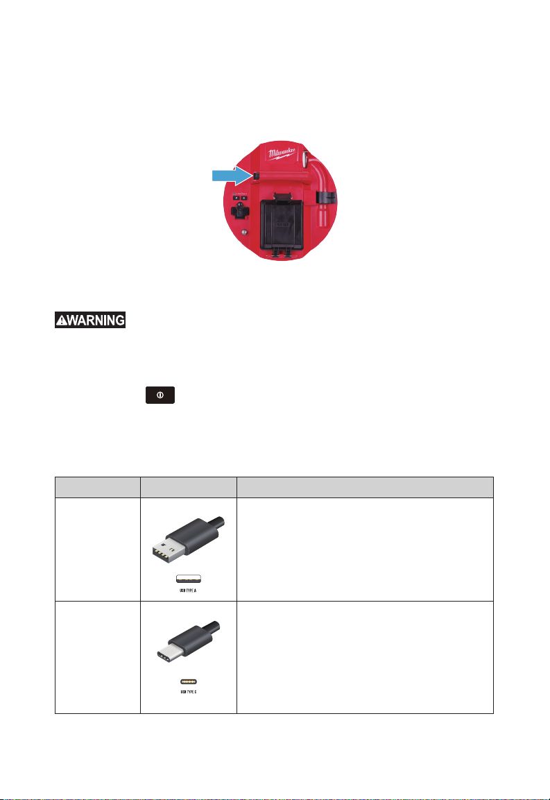
3 M18™ 500GB CONTROL HUB
Removing the M18 500GB CONTROL HUB
1. On the back of the reel, turn the push cable drum brake locking knob counterclockwise
to unlock.
2. Remove the spring from the spring holder.
3. Push the push cable and spring into the push cable drum.
4. Press the unlock button and remove.
3.3 Using the M18™ 500GB CONTROL HUB
charging instructions, read the operator's manual supplied with your charger and
battery.
Recharge only with the charger specied for the battery. For specic
3.3.1 Power on/off
Press the Power button on the M18™ 500GB CONTROL HUB. The buttons on
the CONTROL HUB will illuminate, showing that the power is on. The CONTROL HUB
symbol will appear in the status bar of the M18™ WIRELESS MONITOR along with the
CONTROL HUB's battery state.
3.3.2 USB Ports
Port Type Illustration Purpose
The USB-A port is the day to day use port. It
allows for direct recording of video and picture
USB-A Port
USB-C Port
files or transferring files from the M18™ 500GB
CONTROL HUB INTERNAL DRIVE.
This drive is also used to perform firmware
updates to CONTROL HUB.
The USB-C port is used for:
Connecting the M18™ WIRELESS MONITOR to
the M18™ 500GB CONTROL HUB bypassing a
WI-FI connection.
Power the M18™ 500GB CONTROL HUB from
the M18™ WIRELESS MONITOR when no battery
is present in the HUB or vice versa.
48
Page 53
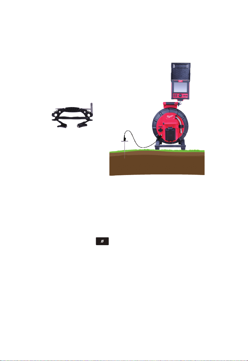
3 M18™ 500GB CONTROL HUB
3.3.3 Grounding Post
The grounding post must be used while using the LINE TRACE feature to trace push
cable. The M18™ 500GB CONTROL HUB must be grounded to close the current loop to
send out a good locate signal. Use the supplied grounding cable assembly with ground
stake to ground the CONTROL HUB to earth.
CONTROL HUB grounding
assembly
A Grounded M18™ 500GB CONTROL HUB
3.3.4 Distance Counter Reset
As the PIPELINE INSPECTION REEL rotates, the distance of push cable deployed is
shown on the status bar of the WIRELESS MONITOR in Feet and 10th of an inch or
Meters and 10th of a meter. When pulling back the push cable if the counter passes "0" it
will begin to count in negative footage. For example -1.0FT, -2.0FT.
There are two methods to reset the distance count.
Press the DISTANCE RESET button on the M18™ 500GB CONTROL HUB or
M18™ WIRELESS MONITOR and the distance shown in the WIRELESS MONITOR will
reset to "0".
3.3.5 Camera Test Port
As a troubleshooting tool, on the rear of the M18™ 500GB CONTROL HUB, a Camera
Test Port is available. If ever any camera head problems occur, the user can isolate the
camera head from the rest of the system for troubleshooting.
49
Page 54
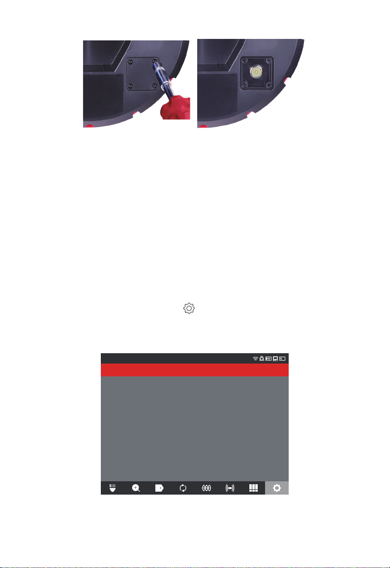
3 M18™ 500GB CONTROL HUB
Remove the four combination head screws to access the camera test port
1. With the CONTROL HUB powered off, remove it from the reel.
2. On the rear of the CONTROL HUB, remove the four combination head screws from
the camera test port cover.
3. Screw the camera head onto the male threads of the test port. Hand tighten only.
4. Power on the CONTROL HUB.
5. Power on the M18™ WIRELESS MONITOR or tablet running the Milwaukee® Pipeline
Inspection App, and connect to the CONTROL HUB checking for picture and control of
the cameras LED's.
3.4 Formatting the M18™ CONTROL HUB INTERNAL
and THUMB DRIVEs
This setting allows the formatting of the M18™ 500GB CONTROL HUB's Internal 500GB
Drive or Thumb Drive.
The system requires that Thumb Drives be formatted in the FAT32 le system.
1. Turn the navigation dial to SETTINGS , press the navigation dial.
2. Turn the navigation dial to FORMAT DISK, press the navigation dial to enter the sub-
menu.
Select the CONTROL HUB Internal Drive (HUB SSD) or the CONTROL HUB Thumb
Drive (HUB USB) and press the navigation dial.
SETTINGS
CONTROL HUB INTERNAL DRIVE
CONTROL HUB THUMB DRIVE
50
Page 55
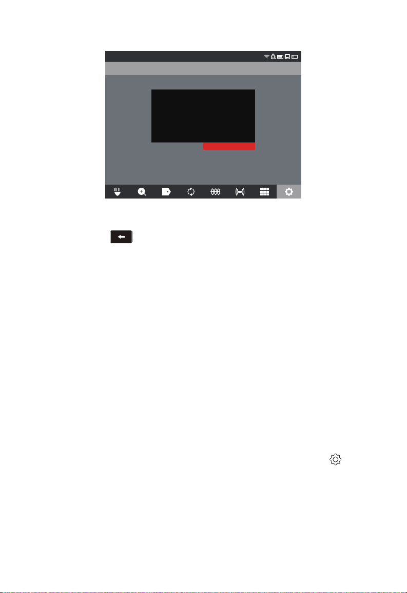
3 M18™ 500GB CONTROL HUB
3. Press the navigation dial and accept the on-screen message to continue.
SETTINGS
CONTROL HUB INTERNAL DRIVE
CONTROL HUB THUMB DRIVE
Are you sure you want to delete the files on
the disk: “CONTROL HUB INTERNAL
DRIVE”
CANCEL ERASE
4. The selected drive will be formatted, and the system will return to the SETTINGS
menu.
5. Press the Back key to return to the main viewing screen.
3.5 FACTORY RESET & SYSTEM UPDATES – M18™
500GB CONTROL HUB
These two tasks can be accomplished by using the M18™ 500GB CONTROL HUB and
M18™ WIRELESS MONITOR or a tablet running the Milwaukee® Pipeline Inspection
App.
3.5.1 FACTORY RESET - M18™ 500GB CONTROL HUB
Performing a factory reset will reset the M18™ 500GB CONTROL HUB to the factory
defaults.
In the CONTROL HUB, the functionality that will reset to the factory default will be:
• LABELS will be erased
• VIDEO and IMAGE settings back to default :1080P
• The COMPANY NAME is removed
• SONDE frequency back to default
• LINE TRACE back to default
• SCREEN SETTINGS back to default: Hue, Brightness, Contrast, Saturation.
• UNITS of measure
1. On the M18™ WIRELESS MONITOR, turn the navigation dial to SETTINGS , press
the navigation dial. Turn the navigation dial to FACTORY RESET, press the navigation
dial to enter the sub-menu.
51
Page 56
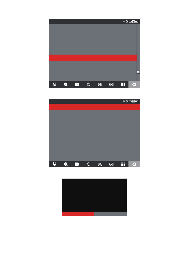
3 M18™ 500GB CONTROL HUB
Cancel OK
SETTINGS
SCREEN SETTINGS
DATE & TIME
UNITS
Feet
LANGUAGE
English
MANAGE JOBS
2019/05/10 6 FILES
SYSTEM UPDATE
FACTORY RESET
ABOUT
SERVICE & SUPPORT
2. Select FACTORY RESET CONTROL HUB and press the navigation dial.
SETTINGS
FACTORY RESET CONTROL HUB
FACTORY RESET WIRELESS MONITOR
3. Read and acknowledge the Reset message by selecting OK.
Do you want to factory reset the control Hub?
The factory reset is now complete, and the system is returned to the FACTORY RESET
sub-menu.
52
Page 57
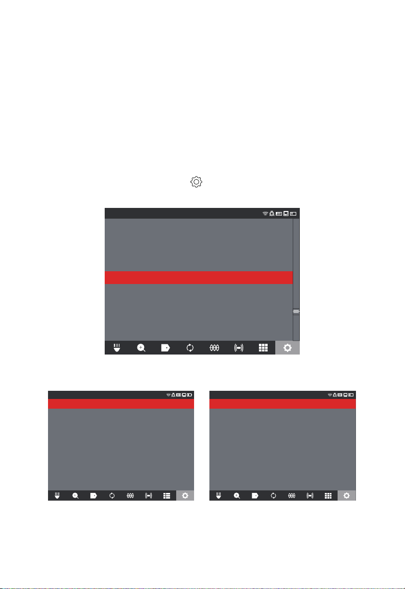
3 M18™ 500GB CONTROL HUB
3.5.2 SYSTEM UPDATE - M18™ 500GB CONTROL HUB
Before updating a system, go to the ABOUT section of the SETTINGS menu and make a
note of the current rmware revisions in the system.
Firmware updates can be performed with the m18™ WIRELESS MONITOR or tablet
running the Milwaukee® Pipeline Inspection App.
1. Turn on both the M18™ 500GB CONTROL HUB and M18™ WIRELESS MONITOR or
tablet running the Milwaukee® Pipeline Inspection App.
2. Check that the WIRELESS MONITOR or tablet running the Milwaukee® Pipeline
Inspection App is connected to the CONTROL HUB by WI-FI. If it is not connected,
you will need to connect it.
3. Insert a Thumb Drive with the rmware update on it into the CONTROL HUB's USB-A
port.
4. Turn the navigation dial to SETTINGS , press the navigation dial.
5. Turn the navigation dial to SYSTEM UPDATE, press the navigation dial to enter the
submenu.
SETTINGS
SCREEN SETTINGS
DATE & TIME
UNITS
Feet
LANGUAGE
English
MANAGE JOBS
2019/05/10 6 FILES
SYSTEM UPDATE
FACTORY RESET
ABOUT
SERVICE & SUPPORT
6. Select CONTROL HUB and press the navigation dial. The filename of the update
should be seen in this window. Press the navigation dial to begin the update.
CONTROL HUB
WIRELESS MONITOR
SETTINGS
MTCam_hub.bin
SETTINGS
Select CONTROL HUB The rmware update is shown
53
Page 58

3 M18™ 500GB CONTROL HUB
Cancel OK
OK
7. Read and acknowledge the warning message by selecting OK.
Selecting OK will run a firmware update in
the Control Hub. Please do not interrupt the
update process after it has started.
8. A progress indicator will appear showing the progress of the update.
The Control Hub is updating...
58%
9. A conrmation message will appear when the update is complete. Select OK to reboot
the system.
The Control Hub was successfully updated
and it will be restarted.
10. Go to the ABOUT option in the SETTINGS menu to check that the rmware revision
numbers have updated.
54
Page 59
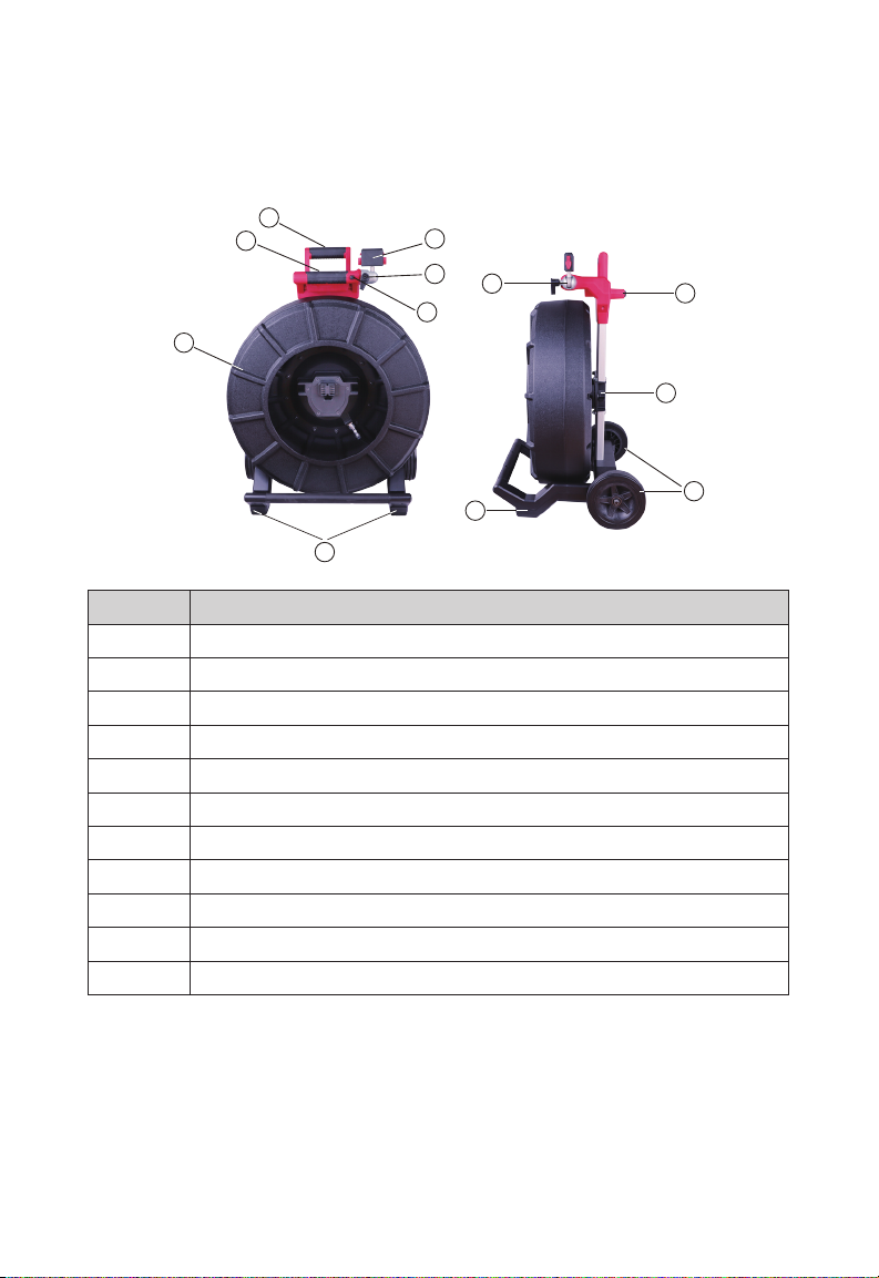
4 PIPELINE INSPECTION REEL
4
4. PIPELINE INSPECTION REEL
4.1 200' PIPELINE INSPECTION REEL Overview
1
2
3
7
6
8
5
9
10
4
Reference Description
1. Retractable handle (shown in the lowered position)
2. Retractable handle lock and release button
3. Push cable drum and push cable
4. Vertical position feet
5. WIRELESS MONITOR rotation lock
6. Tilt lock
7. WIRELESS MONITOR mount/TABLET MOUNT connector
8. WIRELESS MONITOR mount swivel
9. Horizontal position feet
10. Push cable drum brake
11. Wheels
11
55
Page 60
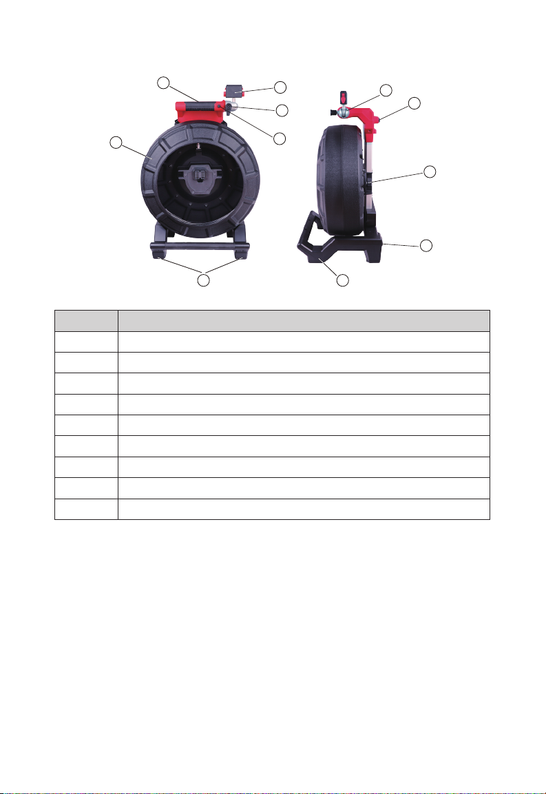
4 PIPELINE INSPECTION REEL
4.2 120' PIPELINE INSPECTION REEL Overview
1
6
5
7
8
2
3
4
Reference Description
1. Handle
2. Push cable drum and push cable
3. Vertical position feet
4. WIRELESS MONITOR rotation lock
5. WIRELESS MONITOR tilt lock
6. WIRELESS MONITOR/TABLET MOUNT connector
7. WIRELESS MONITOR mount swivel
8. Horizontal position feet
9. Push cable drum brake
9
8
3
56
Page 61
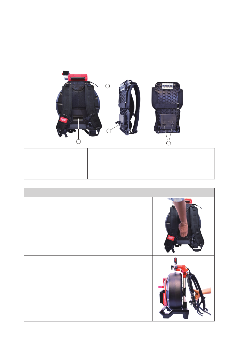
4 PIPELINE INSPECTION REEL
4.3 Installing the Backpack Plate
The 120' PIPELINE INSPECTION REEL comes with a backpack mounting plate which
allows the reel to be carried as a backpack. This is useful for transporting the small reel to
and from the job site. This is extremely helpful for climbing stairs or ladders.
CAUTION - Use care when transporting this tool when the reel and backpack are
connected. Tipping may occur.
2
3
1
The rear of 120' Pipeline
Backpack plate side view Backpack plate rear view
Inspection with backpack
plate installed
1. Release lever 2. Top mounting plate
3. Bottom retaining hooks
Removing the backpack plate
1. Lift the release lever to unlock the backpack
plate.
2. Pull the bottom of the backplate away from the reel and
downward in one motion.
4
4. Male mounting post
57
Page 62
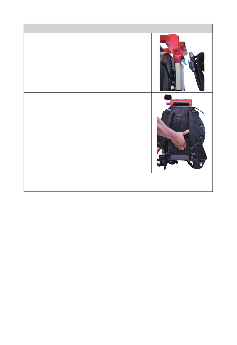
4 PIPELINE INSPECTION REEL
Installing the backpack plate
1. Push the top mounting plate into the reels top mounting
receptacle.
2. Now push the bottom of the backpack into the reel lining
up the male mounting post.
3. Push with the palm of the hand against the bottom of the backpack until it locks in
place. Give a slight tug to make sure that it is locked in place.
58
Page 63
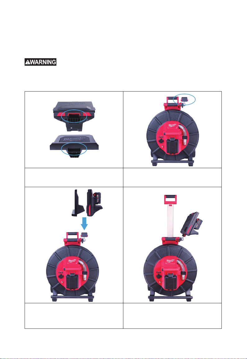
4 PIPELINE INSPECTION REEL
4.4 Mounting the M18™ WIRELESS MONITOR
The M18™ WIRELESS MONITOR or TABLET MOUNT can be mounted on both the mini
and standard size PIPELINE INSPECTION REELs. Once mounted, the monitor or tablet
can be adjusted for the best viewing angle in both vertical and horizontal positions.
do not allow battery to contact corrosive or conductive uid.
Mount receptacle on the bottom of
WIRELESS MONITOR and TABLET
To reduce the risk of short circuit, when setting tool or battery down,
WIRELESS MONITOR and TABLET
MOUNT
MOUNT on PIPELINE INSPECTION REEL
1. Line up the WIRELESS MONITOR or
TABLET MOUNT mounting receptacle
with the mounting block on the
PIPELINE INSPECTION REEL.
2. Lower in place and press until the
locking click is heard.
59
Page 64
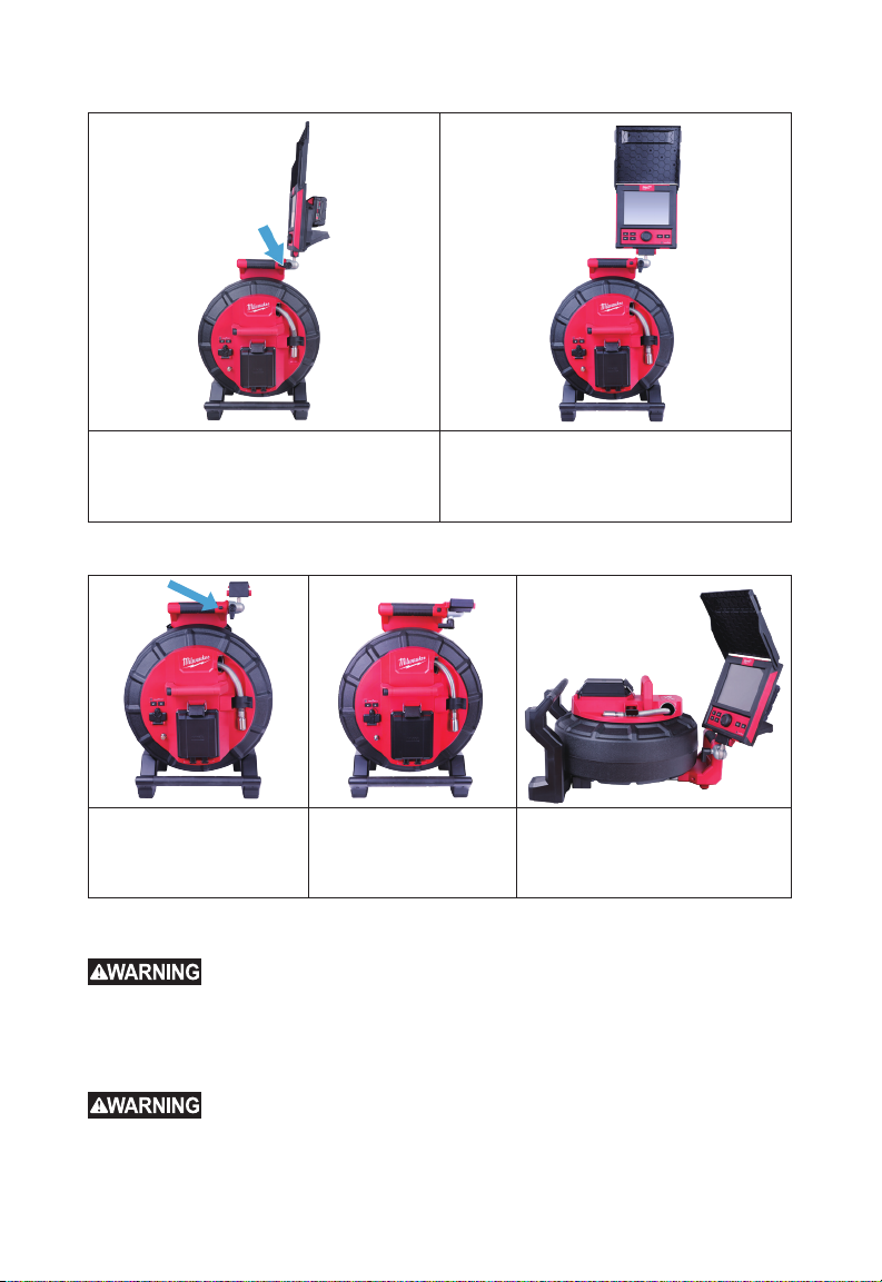
4 PIPELINE INSPECTION REEL
Adjust the viewing angle of the WIRELESS MONITOR:
1. Loosen the adjustment arm by turning
the arm clockwise.
Adjust the tilt angle of the WIRELESS MONITOR:
1. Press the locking tilt
button to unlock the
adjustment block.
2. Turn the mounting
block towards the
opening of the drum
until it locks in place.
2. Move the WIRELESS MONITOR to the
desired angle.
3. Tighten the adjustment arm
counterclockwise until tight.
3. Adjusting the tilt angle is useful
when using the reel in the
horizontal position.
4.5 Using the PIPELINE INSPECTION REEL
and respirator when chemicals, bacteria or other toxic or infectious substances
are suspected to be in a drain line. Drains may contain chemicals, bacteria and other
substances that may cause burns, be toxic or infectious or may result in other serious
personal injury.
Use latex or rubber gloves, goggles, face shields, protective clothing,
always check the work area before beginning a job. Do not allow cable to contact
electrical, chemical, or moving hazards.
Do not use the push cable to clear clogs or move obstructions. This is not a drain cleaner!
To reduce the risk of explosion, electric shock and property damage,
60
Page 65
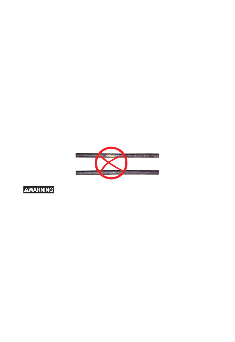
4 PIPELINE INSPECTION REEL
1. Position the reel on a at surface approximately three to six feet or one to two meters
from the entry point. This will provide enough space to work with the push cable
without a lot of slack dragging on the ground. Use the friction brake to slow down the
movement of the push cable drum if needed.
Using the reel in a horizontal position makes the width between the feet greater. This
will give the reel more stability if on uneven surfaces and will lower the height when in
conned spaces.
2. Unlock the spring then loosen the friction brake so that the push cable drum can spin.
3. The push cable is now ready to be deployed into the pipe.
4.6 Push Cable
Check Push Cable for Wear - Visually inspect the push cable for cuts, kinks, and
abrasions as it is retrieved back into the cable cage. If the jacket is cut or worn to the
point that the yellow or white Kevlar braid can be seen, then it is time to replace the push
cable. Using the push cable with open cuts will result in water and moisture entering the
push cable and eventually traveling through it, causing a degraded camera image, or total
image failure.
The push cable sections shown below are examples of badly worn jackets. Push cable
such as this should be replaced as soon as possible.
immerse your tool, battery pack or charger in uid or allow a uid to ow inside
them. Always remove battery pack before cleaning.
Keep the Push cable and Termination Spring Assembly dry and clean – When retrieving
the push cable keep a clean, dry rag in one hand and wipe down the push cable as it
moves through it. At the end of the day,use low-pressure water to rinse off the camera
head and rinse away accumulated dirt and debris that may be caught in the spring. Shake
dry or use low-pressure air to blow the excess water away and dry off the parts. The
Camera Head, Push Cable and Termination Parts are exposed to very harsh chemicals in
day-to-day use. Keeping a clean system will help prolong the life of these parts.
Maintain proper control of the push cable – Attempting to pull the push cable out of
the reel while the reel is locked will result in the push cable collapsing in the reel and
stressing the push cable. Pushing the push cable back into the reel while it is locked may
cause the reel to tip over or kink the cable.
To reduce the risk of re, personal injury, and product damage, never
61
Page 66
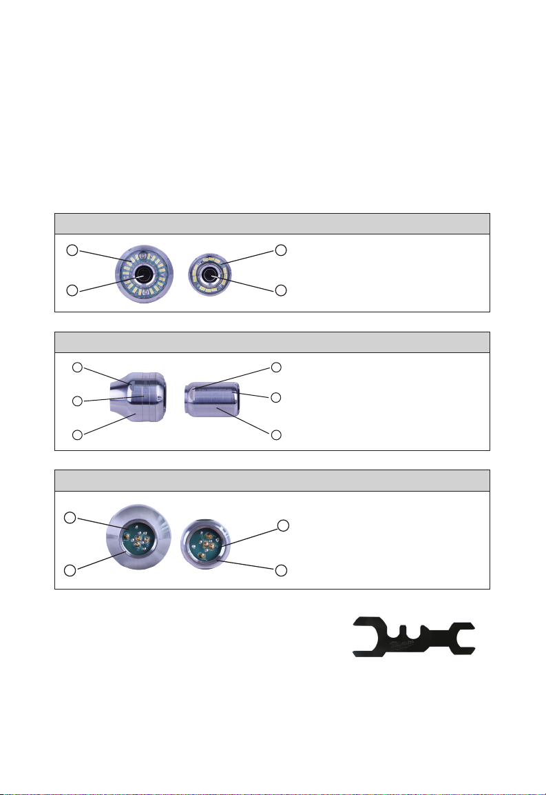
5 Camera Heads and Spring Assembly
5. Camera Heads and Spring Assembly
5.1 Camera Heads
The 200' PIPELINE INSPECTION REEL comes with a 34mm diameter camera head and
the 120' PIPELINE INSPECTION REEL comes with a 25mm diameter version. A custom
camera wrench is provided for their removal and installation. Both camera heads are
provided with a plastic protective cover. Always use the protective cover while using the
PIPELINE INSPECTION REEL.
Face: 34mm 25mm
1
1
1. Polycarbonate LED cover
2
2. Sapphire glass lens
2
Body: 34mm 25mm
3
2
3
1. Main Housing
2
2. Serial number location
3. Wrench Flats
1 1
Rear: 34mm 25mm
1
1
1. Connecting contact pins
2. Internal base threads
2
2
A custom camera wrench is supplied with the PIPELINE
INSPECTION REEL. Use the wrench to tighten and
remove the spring assembly and camera head.
Do not overtighten or use excessive force!
Custom Camera Wrench
62
Page 67
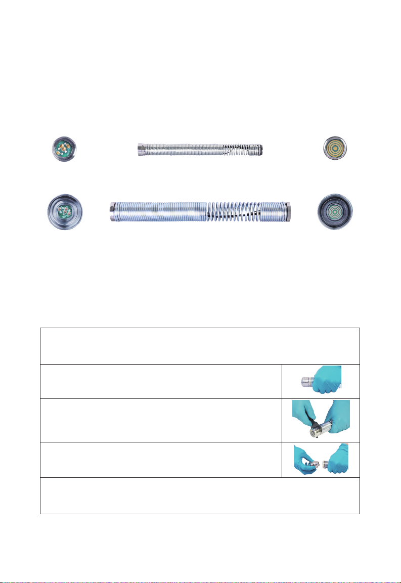
5 Camera Heads and Spring Assembly
5.2 Parts of the Spring Assembly
The spring assembly is comprised of the parts that connect the camera head on one end
to the push cable on the other. The reel end of the assembly has wrench ats for removal
and installation.
The spring termination assembly consists of an all-in-one spring, coiled cable assembly,
and steel lanyard.
Spring Assembly
Reel End 120' PIPELINE INSPECTION REEL Spring Assembly Camera End
Reel End 200' PIPELINE INSPECTION REEL Spring Assembly Camera End
5.3 Removing and Installing the Camera Heads
Avoid touching the green circuit board or gold pins on the spring assembly or camera
head with bare hands. Touching these will transfer oils from the fingers to these
components, which may lead to premature corrosion. Wear clean, dry rubber gloves if
possible.
5.3.1 Camera Head Removal
Before removing the camera head, wipe it dry, and remove any dirt that may fall into
the camera connection areas.
1. Grasp the spring assembly close to the base of the camera
head.
2. Use the camera wrench to loosen the camera head by
turning in a counterclockwise direction.
3. After the camera head is loose, continue to unscrew the
camera untill removed.
Place the camera head in an area where the contact pins will not be damaged.
63
Page 68
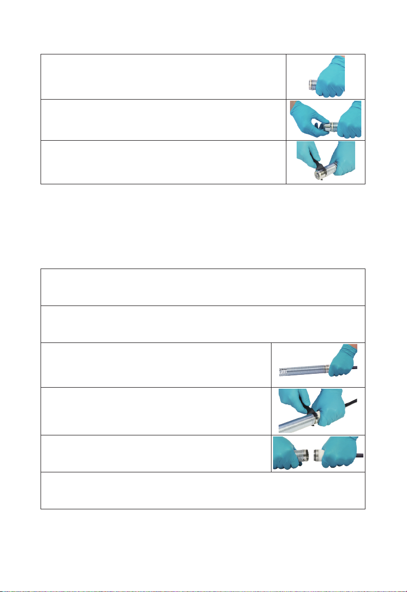
5 Camera Heads and Spring Assembly
5.3.2 Camera Head Installation
1. Grasp the spring assembly close to the camera head end of
the spring assembly.
2. Slowly screw on the camera head in a clockwise direction,
being careful not to cross thread the connections.
3. Use the supplied wrench to tighten the camera head.
Do not overtighten or use excessive force!
5.4 Removing and Installing the Spring Assembly
Avoid touching the green circuit board or gold pins of the spring assembly or camera head
with bare hands. Touching these will transfer oils from the ngers to these components,
which may lead to premature corrosion. Wear clean rubber gloves if possible.
5.4.1 Spring Assembly Removal
Before removing the spring assembly, wipe it dry and remove any dirt that may fall into
either end of the spring's connections.
Remove the camera head following the instructions shown in 5.3.1
1. Grasp the sonde compartment at the base of the
termination area where it connects to the push cable.
2. With the other hand, use the supplied wrench to loosen
the spring assembly.
3. After the spring assembly is loose, continue to unscrew ir
counterclockwise untill removed.
Place the spring assembly in an area where the contact pins will not be harmed.
64
Page 69
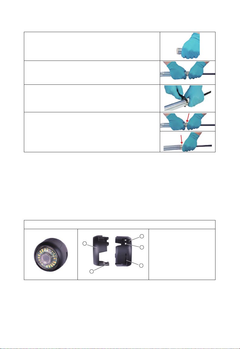
5 Camera Heads and Spring Assembly
5.4.2 Spring Assembly Installation
1. Grasp the sonde compartment at the base of the
termination area where it connects to the push cable.
2. Slowly screw the spring assembly on in a clockwise
direction being careful not to cross thread the
connections.
3. Use the supplied wrench to tighten.
4. The spring assembly is installed correctly when the black
O-Ring at the base of the sonde compartment is no
longer visible.
Do not overtighten or use excessive force!
5.5 Camera Skids and Protective Covers
Protective Covers – are covers that fit over the 25mm and 34mm camera heads.
The protective covers are provided with all PIPELINE INSPECTION REEL systems or
replacement camera heads.
Skids - are devices that attach to the spring assembly to keep the camera head off the
oor of the pipe and prevent the camera head from making direct contact with the pipe.
5.5.1 The Protective Covers
These instructions apply to both the 25mm and 34mm camera heads.
5
1
2
65
1. Top half, (front)
2. Locking tab
4
3. Wrench ats
4. Tab receptacle
3
5. Screwdriver slot
Page 70
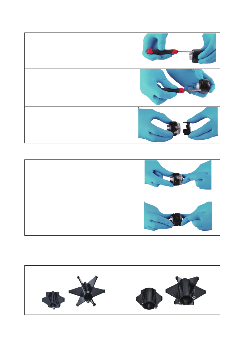
5 Camera Heads and Spring Assembly
5.5.2 Removing the Protective Cover
1. Insert a at screwdriver into the slot and lift
until the locking tab releases.
2. Place your thumb against the locking tab to
prevent it from falling back into place while
moving to the next tab to unlock it.
3. Remove the top portion of the protective
cover.
5.5.3 Installing the Protective Covers
1. Place the rear half of the protective cover on
the back of the camera head.
2. Twist the camera while pressing down so the
cameras wrench ats line up and lock into
the cover.
3. Line up the protective cover locking tabs and
press the top half into the bottom half. Press
until all the locking tabs have snapped into
place, locking the cover in place.
5.5.4 Camera Skids
There are two skids available for both the 25mm and 34mm camera heads. A small 3"
version and a medium 4" version.
25mm Camera Skids 34mm Camera Skids
66
Page 71
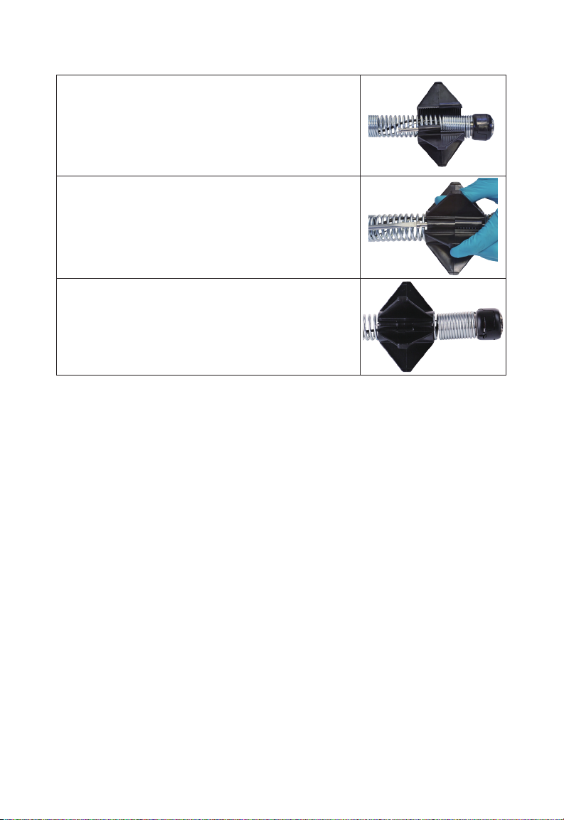
5 Camera Heads and Spring Assembly
5.5.5 Installing the Camera Skid
1. Fully open the camera skid, place the spring into the
skid.
Position the skid so that the camera is level.
2. Close the camera skid and pinch the ns together
while pushing the screw into the hole.
3. Screw until tightened.
Do not overtighten or use excessive force!
67
Page 72
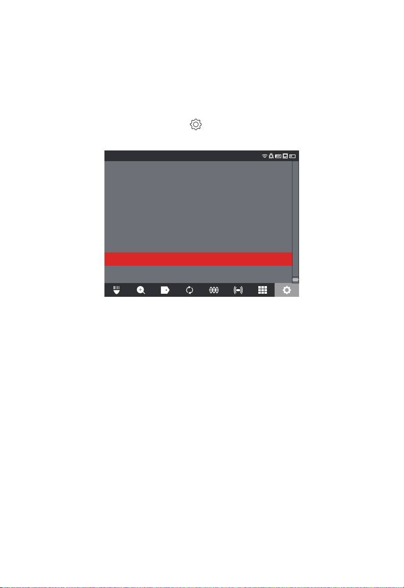
6 Service & Support
6. Service & Support
If any part of your PIPELINE INSPECTION SYSTEM should require service, you will
nd Milwaukee Tool's service page and support number in the SERVICE & SUPPORT
directory.
1. Turn the navigation dial to SETTINGS , press the navigation dial.
2. Turn the navigation dial to SERVICE & SUPPORT, press the navigation dial to enter
the directory.
SETTINGS
SCREEN SETTINGS
DATE & TIME
UNITS
Feet
LANGUAGE
English
MANAGE JOBS
2019/05/10 6 FILES
SYSTEM UPDATE
FACTORY RESET
ABOUT
SERVICE & SUPPORT
68
Page 73

MANUEL de L'UTILISATEUR
Cat. No.
2970-20: M18™ Unité de contrôle 500GB
2971-20: M18™ Moniteur de Commande Sans Fil
2973-20: 36,5 M Touret de cable pour Inspection de canalisation
2974-20: 60,9 M Touret de cable pour Inspection de canalisation
48-53-2970 - Support de tablette
Français
Page 74

Page 75

RÈGLES DE SÉCURITÉ GÉNÉRALES RELATIVES AUX OUTILS
ÉLECTRIQUES
instructions, les illustrations et les précisions fournis avec cet outil électrique.
Ne pas suivre l’ensemble des instructions décrites ci-dessous peut entraîner une
électrocution, un incendie ou des blessures graves. Conserver tous les avertissements
et instructions pour référence ultérieure. Le terme « outil électrique », utilisé dans tous
les avertissements ci-dessous, désigne tout outil fonctionnant sur secteur (câblé) ou sur
batteries (sans l).
Veuillez lire tous les avertissements et toutes les
AIRE DE TRAVAIL SÉCURITAIRE
• Veillez à ce que l’aire de travail soit propre et bien éclairée. Le désordre et le
manque de lumière favorisent les accidents.
• Ne pas utiliser d’outils électriques dans d’atmosphères explosives, par exemple
en présence de liquides, gaz ou poussières inammables. Les outils électriques
produisent des étincelles risquant d’enammer les poussières ou les vapeurs.
• S’assurer que les enfants et les badauds se trouvent à une distance sécuritaire
au moment d’utiliser ce produit. Les distractions peuvent causer une perte de
contrôle.
SÉCURITÉ ÉLECTRIQUE
• Les fiches des outils électriques doivent correspondre à la prise secteur
utilisée. Ne jamais modifier la fiche, de quelque façon que ce soit. Ne jamais
utiliser d'adaptateurs de che avec des outils mis à la terre. Les ches et prises
non modiées minimisent le risque de choc électrique.
• Éviter tout contact avec des surfaces mises à la terre comme des tuyaux, des
radiateurs, des cuisinières et des réfrigérateurs. Le risque de choc électrique est
accru lorsque le corps est mis à la terre.
• Ne pas exposer les outils électriques à l'eau ou l'humidité. La pénétration d’eau
dans ces outils accroît le risque de choc électrique.
• Ne pas maltraiter le cordon d’alimentation. Ne jamais utiliser le cordon
d’alimentation pour transporter l’outil et ne jamais débrancher ce dernier en
tirant sur le cordon. Garder le cordon à l’écart de la chaleur, de l’huile, des
objets tranchants et des pièces en mouvement. Un cordon endommagé ou
emmêlé accroît le risque de choc électrique.
• Pour les travaux à l’extérieur, utiliser un cordon spécialement conçu à cet effet.
L’utilisation d’un cordon pour l’extérieur minimise les risques de choc électrique.
• Si l’utilisation d’un outil électrique est inévitable dans un endroit humide, utiliser
une source d’alimentation munie d’un disjoncteur de fuite de terre. L’utilisation
d’un tel dispositif minimise le risque de choc électrique.
SÉCURITÉ PERSONNELLE
• Rester attentif, prêter attention au travail et faire preuve de bon sens lors de
l'utilisation de tout outil électrique. Ne pas utiliser cet appareil en cas de fatigue
ou sous l’influence de l’alcool, de drogues ou de médicaments. Un moment
d’inattention pendant l’utilisation d’un outil électrique peur entraîner des blessures graves.
• Porter l’équipement de protection individuel requis. Toujours porter une
protection oculaire. Selon les conditions, porter aussi un masque antipoussière, des
bottes de sécurité antidérapantes, un casque protecteur ou une protection auditive
an de minimiser les blessures.
1
Page 76

• Éviter les démarrages accidentels. S’assurer que la gâchette est en position
d’arrêt avant de brancher l’outil à une source de courant, d’insérer la batterie,
de le ramasser ou de le transporter. Le fait de transporter un outil électrique en
gardant le doigt sur la gâchette ou de mettre sous tension un outil électrique lorsque la
gâchette est en position de marche favorise les accidents.
• Retirer les clés de réglage avant de mettre l’outil en marche. Une clé laissée sur
une pièce rotative de l’outil peut causer des blessures.
• Ne pas travailler hors de portée. Toujours se tenir bien campé et en équilibre.
Une bonne stabilité procure un meilleur contrôle de l’outil électrique en cas d’imprévus.
• Porter une tenue appropriée. Ne porter ni vêtements amples, ni bijoux. Garder
les cheveux et les vêtements à l’écart des pièces en mouvement. Les vêtements
flottants, les bijoux ou les cheveux longs risquent d’être happés par les pièces en
mouvement.
• Si les outils sont munis de dispositifs de dépoussiérage, s’assurer qu’ils sont
connectés et correctement utilisés. L’utilisation d’un collecteur de poussière sert à
réduire les dangers liés à la poussière.
• Ne pas laisser la familiarité avec l’utilisation fréquente de l’outil vous faire sentir
content de soi et ignorer les principes fondamentaux de sécurité pour l’outil. Un
manque d’attention, même d’une fraction de seconde, pourra entraîner des blessures
graves.
UTILISATION ET ENTRETIEN DES OUTILS MOTORISÉS
• Ne pas forcer l’outil électrique. Utiliser l'outil approprié pour l'application. Un
outil approprié exécutera le travail mieux et de façon moins dangereuse s’il est utilisé
dans les limites prévues.
• Ne pas utiliser l'outil si le commutateur ne permet pas de le mettre en marche
ou de l’arrêter. Tout outil qui ne peut pas être contrôlé par son commutateur est
dangereux et doit être réparé.
• Débrancher la fiche de la source d’alimentation et/ou retirer le bloc-piles, s’il
est amovible, de la source d’alimentation avant d’entreprendre tout action de
réglage, de changer les accessoires ou d’entreposer les outils électriques. Ces
mesures de sécurité préventives réduisent les risques de démarrage accidentel de l'outil.
• Entreposer l’outil électrique hors de la portée des enfants et interdire à
quiconque de l’utiliser si la personne ne connaît pas bien le produit ou les
instructions. Les outils sont dangereux dans les mains d’utilisateurs novices.
• Entretenir les outils électriques et les accessoires. Vérifier qu'aucune pièce
mobile n'est mal alignée ou bloquée, qu'aucune pièce n'est brisée et s'assurer
qu'aucun autre problème risque d'affecter le bon fonctionnement de l'outil
électrique. En cas de dommages, faire réparer l’outil avant de l’utiliser. Plusieurs
accidents sont causés par des produits mal entretenus.
• Garder les outils bien affûtés et propres. Des outils correctement entretenus et
dont les tranchants sont bien affûtés risquent moins de se bloquer et sont plus faciles
à contrôler.
• Utiliser l’outil électrique, les accessoires, les forêts, etc. conformément à
ces instructions, en tenant compte des conditions de travail et de la tâche à
effectuer. L'usage d'un outil électrique pour des applications pour lesquelles il n'est
pas conçu peut être dangereux.
• Garder les poignées et les surfaces de prise sèches, propres et exemptes d’huile
et de graisse. Les poignées et les surfaces de prise glissantes ne permettent pas le
maniement et le contrôle sécuritaires de l’outil dans des situations imprévues.
2
Page 77

UTILISATION ET ENTRETIEN DE LA BATTERIE
• Pour recharger les batteries, utiliser seulement le chargeur spécifié par le
fabricant. Un chargeur pouvant convenir à un type de bloc-piles peut entraîner un
risque d’incendie lorsqu’il est utilisé avec un autre type de bloc-piles.
• N’utiliser l’outil électrique qu’avec une batterie recommandée. L’utilisation de tout
autre bloc-piles peut poser un risque de blessures et d’incendie.
• Lorsque la batterie n’est pas utilisée, la tenir éloignée des objets en métal tels
que les trombones, les pièces de monnaie, les clés, les clous, les vis ou d’autres
petits objets métalliques qui pourraient connecter les bornes. Le court-circuitage
des bornes d’une batterie peut entraîner des brûlures ou un incendie.
• En cas d'usage abusif, du liquide peut s'échapper des piles ; éviter tout contact
avec ce liquide. En cas de contact accidentel, rincer immédiatement les parties
atteintes avec de l’eau. Si le liquide entre en contact avec les yeux, consulter
un médecin. Le liquide s'échappant des batteries peut causer des irritations ou des
brûlures.
• Ne pas utiliser les blocs-piles ni les outils endommagés ou modifiés. Les
batteries endommagées ou modiées pourront montrer un comportement imprévisible
qui entraînera des incendies, des explosions et même de risques de blessures.
• Ne pas exposer les blocs-piles ni les outils à d’incendies ou de températures
extrêmes. L’exposition à des feux ou des températures excédantes les 130 ºC (265
ºF) pourra entraîner des explosions.
• Suivre toutes les consignes de chargement de batteries et ne pas charger ni
le bloc-piles ni l’outil à de températures supérieures à celles listées dans les
instructions. Le chargement inadéquat ou les températures excessives pourront
endommager la batterie et augmenter le risque d’incendie.
DÉPANNAGE
• Les réparations doivent être confiées à un technicien qualifié, utilisant
exclusivement des pièces identiques à celles d’origine. Le maintien de la sûreté
de l’outil électrique sera ainsi assuré.
• Ne jamais entretenir les bloc-piles endommagés. L’entretien des blocs-piles ne
devra être coné qu’au fabricant ou aux fournisseurs de service autorisés.
RÈGLES DE SÉCURITÉ PARTICULIÈRES POUR LES SYSTÈMES
D’INSPECTION DE TUYAUX
• Porter de gants en latex ou en caoutchouc, de lunettes de sécurité, de masques
de sécurité, de vêtements de sécurité et un respirateur lorsqu’il est soupçonné de
la présence de produits chimiques, de bactéries ou d’autres substances toxiques
ou infectieuses dans le tuyau de vidange. Les tuyaux peuvent avoir de produits
chimiques, de bactéries et d’autres substances qui pourront provoquer des brûlures,
être toxiques ou infectieuses ou bien, entraîner d’autres blessures physiques graves.
• Utiliser des bonnes pratiques d’hygiène. Ne jamais manger ni fumer pendant
l’utilisation ou l’opération de l’outil. Après avoir manipulé ou utilisé d’équipement,
se laver les mains et d’autres parties du corps ayant été exposés au contenu de
tuyau à l’eau chaude et au savon. Ceci aidera à minimiser la probabilité de risques
sanitaires causés par l’exposition à de matériel toxique ou infectieux.
• Toujours vérifier l’aire de travail avant de commencer à travailler. S’assurer
que le câble n’est pas en contact avec aucun type d’élément posant un risque
électrique, chimique ou de mouvement.
3
Page 78

• Ne pas utiliser le câble pour retirer ou bouger d’objets représentant une
obstruction. Ceci n’est pas un dégorgeoir !
• Avant d’utiliser le câble, il faut vérier qu’il ne montre pas de signes ni d’usure
ni de dommages. Ne pas tordre, ni plier, ni trop courber les câbles. Remplacer
tout câble usé ou endommagé avant d’utiliser l’outil.
• Pour réduire les risques d’incendie, de blessure et dommages sur le produit,
provoqués par des courts-circuits, ne jamais plonger votre outil, bloc-piles ou
chargeur dans un uide et ne pas permettre qu’un uide entre là-dedans. Les
uides corrosifs et conducteurs, tels que l’eau de mer, quelques produits chimiques
industriels et solutions d’eau de Javel ou d’autres produits ayant de l’hypochlorite, etc.,
pourront provoquer des courts-circuits.
• Ne recharger la batterie qu’avec le chargeur spécié. Pour prendre connaissance
des instructions relatives à la charge, lire le manuel d’utilisation fourni avec le chargeur
et la batterie.
• AVERTISSEMENT Ne pas transporter cet outil quand le dévidoir et le bloc-piles
soient branchés. Le basculement peut survenir.
• Faites toujours preuve de bons sens et procédez avec prudence lors de
l’utilisation d’outils. C'est impossible de prévoir toutes les situations qui pourraient
avoir un résultat dangereux. N’utilisez pas cet outil si vous ne comprenez pas ces
instructions d’opération ou si vous pensez que le travail dépasse votre capacité ;
veuillez contacter Milwaukee Tool ou un professionnel pour recevoir plus d’information
ou formation.
• Maintenir en état les étiquettes et les plaques signalétiques. Des informations
importantes y gurent. Si elles sont illisibles ou manquantes, contacter un centre de
services et d’entretien MILWAUKEE pour un remplacement gratuit.
•
du sciage, du meulage, du perçage et d’autres opérations de construction contient
de produits chimiques qui sont connus pour causer le cancer, des malformations
congénitales ou des lésions de l’appareil reproducteur. Voici certains exemples de ces
produits chimiques :
• le plomb contenu dans la peinture au plomb
• la silice cristalline contenue dans les briques, le ciment et d'autres produits de
maçonnerie, ainsi que
• l'arsenic et le chrome contenus dans le bois de construction traité par produits
chimiques.
Le risque posé par l’exposition à ces produits varie en fonction de la fréquence de ce
type de travail. Pour minimiser les risques d'exposition à ces produits chimiques, travailler
dans un endroit bien aéré et utiliser des équipements de sécurité approuvés, tels que les
masques antipoussière spécialement conçus pour ltrer les particules microscopiques.
La poussière dégagée par certains matériaux lors du ponçage,
FEDERAL COMMUNICATIONS COMMISSION
résidentiel, ce produit peut causer un brouillage radio, ce qui peut obliger l’utilisateur à
prendre des mesures adéquates.
Cet équipement a été mis à l’essai et il a été déterminé qu’il est conforme aux normes
sur les dispositifs numériques de classe A, selon la partie 15 du Règlement de la FCC
(Commission fédérale des communications des États-Unis). Ces normes ont été xées
pour fournir une protection raisonnable contre un brouillage préjudiciable si l’équipement
est utilisé dans un environnement commercial. Cet équipement produit et utilise de
l’énergie RF. S’il n’est pas installé et utilisé conformément au manuel d’instructions,
Il s’agit d’un produit de classe A. Dans un environnement
4
Page 79
il peut brouiller de manière préjudiciable les radiocommunications. Le fait d’utiliser cet
équipement dans un secteur résidentiel risque de produire un brouillage préjudiciable que
l’utilisateur devra éliminer à ses frais.
Ce dispositif est conforme à la partie 15 du Règlement de la FCC.
Son fonctionnement est soumis aux conditions suivantes :
(1) cet appareil ne doit produire aucun brouillage préjudiciable.
(2) l’appareil doit fonctionner en dépit de tout brouillage produit, y compris le brouillage
pouvant mener à une opération non désirée.
SYMBOLES
Tension
Courant continu
Federal Communications Commission (FCC)
Ne pas laisser le bloc-piles entrer en contact avec aucun uide corrosif
ou conducteur
Pour éviter les chocs électriques, ne pas laisser le produit entrer en
contact avec de composants électriques sous tension
Danger de brûlures chimiques - Garder hors de la portée des enfants
FICHE TECHNIQUE
Tension ……………………………………………. 18 CD
Type de blocs-piles…………………………………… M18™
Type de chargeur…………………………………… M18™
Environnement suggérée
Température de fonctionnement………………. 0° F à 125° F (32º C à 51,66º C)
BLOCS-PILES M18™
conçu pour le bloc-piles. Pour prendre connaissance des instructions relatives à la
charge, lire le manuel d’utilisation fourni avec le chargeur et le bloc-piles.
Enlèvement/insertion du bloc-piles
Pour retirer le bloc-piles, appuyer sur les boutons de relâchement et sortir la batterie de l’outil.
d’accessoires.
Pour insérer le bloc-piles, le glisser dans le corps de l’outil. S’assurer qu’il est bien inséré
en place.
pour cet outil. L’utilisation d’autres types d’accessoires pourrait entraîner des
situations dangereuses.
Ne le recharger qu’à l’aide du chargeur particulièrement
Toujours retirer le bloc-piles avant de changer ou d’enlever
Utiliser seulement d’accessoires spécialement recommandés
5
Page 80
ONE-KEY™
Pour en savoir plus à propos de la fonctionnalité ONE-KEY™ de cet outil, veuillez
consulter la guide de démarrage rapide ci-jointe ou visitez le site d’Internet milwaukeetool.
com/One-Key. Pour télécharger l'appli ONE-KEY™, visitez App Store ou Google Play
dans votre téléphone cellulaire.
Indicateur ONE-KEY™
Bleu xe Le mode sans l est engagé et prêt pour le congurer à l'aide de
l’appli ONE-KEY™.
Bleu clignotant L’outil établit une communication active avec l’appli ONE-KEY™.
Rouge L'outil a un blocage sécuritaire et ne pourra être débloqué que par
le propriétaire
.
BATTERIE INTERNE
Risque de brûlure chimique. Cet appareil contient une pile type
bouton au lithium. Une pile neuve ou usagée peut provoquer de
brûlures internes graves, et entraîner la mort en moins de 2 heures
en cas d'ingestion ou d'insertion dans le corps. Toujours fixer le
couvercle du compartiment des piles. S’il n'est pas fixé de manière
sécurisée, arrêter d'utiliser l'outil, retirer les piles et garder hors de
portée des enfants. Si vous pensez que des piles ont été ingérées ou
insérés dans le corps, consulter un médecin immédiatement.
Une batterie interne est utilisée pour faciliter la fonctionnalité ONE-KEY™ complète.
Pour remplacer le bloc-piles:
1. Retirer le bloc-piles.
2. Retirer les vis et ouvrir la porte du compartiment de batterie.
3. Retirer la vielle batterie, la tenir hors de la portée des enfants et la jeter adéquatement.
4. Insérer la nouvelle batterie (3V CR2032) avec le pôle positif vers le haut.
Fermer la porte du compartiment des piles et serrer fermement la vis.
ENTRETIEN
débrancher le chargeur et retirer le bloc-piles du chargeur ou de l’outil avant
d’effectuer toute opération d’entretien. Ne jamais démonter ni l’outil, ni le bloc-piles
ni le chargeur. Pour TOUTE réparation, contacter un centre de service MILWAUKEE.
Afin de minimiser le risque de blessures, toujours
ENTRETIEN DE L’OUTIL
Garder l’outil, le bloc-piles et le chargeur en bon état en les soumettant à un programme
d’entretien régulier. Inspecter l'outil pour vérifier qu’il ne fait pas de bruits bizarres,
qu'aucune pièce mobile n'est mal alignée ou bloquée, qu'aucune pièce n'est brisée et
s'assurer qu'aucun autre problème risque d'affecter le bon fonctionnement de l'outil.
Retourner l'outil, le chargeur et le bloc-piles à un centre de service MILWAUKEE pour les
faire réparer. Après six mois à un an, selon l’utilisation, coner l’outil, le bloc-piles et le
chargeur à un centre de service MILWAUKEE pour les faire inspecter.
Si l’outil ne démarre pas ou ne fonctionne pas à plein régime une fois le bloc-piles
complètement chargé, nettoyer les contacts dans le compartiment. Si l’outil ne fonctionne
toujours pas, le retourner ainsi que le chargeur et le bloc-piles à un centre de service
MILWAUKEE aux ns de réparation.
6
Page 81

dommages, ne jamais immerger ni l’outil, ni le bloc-piles ni le chargeur dans un
uide et ne pas laisser entrer aucun uide à l’intérieur.
Afin de minimiser le risque de blessures physiques et de
NETTOYAGE
Nettoyer les évents de l’outil des débris et de la poussière. Garder les poignées de l’outil
propres, sèches et exemptes d’huile et de graisse. Utiliser uniquement un savon doux
et un linge humide, puisque certains agents de nettoyage et certains solvants peuvent
détériorer le plastique et les autres pièces isolées. En voici quelques exemples : l’essence,
la térébenthine, les diluants à laque ou à peinture, les solvants chlorés, l’ammoniaque
et les détergents à usage domestique qui en contiennent. Ne jamais utiliser de solvants
inammables ou combustibles autour des outils.
RÉPARATIONS
Aux ns de réparations, retourner l’outil, le bloc-piles et le chargeur au centre de service
le plus proche.
ACCESSOIRES
d’autres types d’accessoires pourrait entraîner des situations dangereuses.
Pour consulter une liste intégrale d’accessoires, visiter le site www.milwaukeetool.com ou
contacter un distributeur.
N'utiliser que les accessoires recommandés. L’utilisation
DÉPANNAGE – ÉTATS-UNIS
1-800-SAWDUST
Lundi à vendredi, 7h00 à 16h30, CST
ou consulter le site www.milwaukeetool.com
Contacter l’Équipe de Service Technique Après-Vente Corporatif si vous avez de
questions techniques, de dépannage/réparations ou à propos de la garantie.
Courriel : [email protected]
Devenez membre du club Heavy Duty en consultant le site web www.milwaukeetool.com;
abonnez-vous pour recevoir d’informations importantes sur vos achats d’outils.
(1.800.729.3878)
DÉPANNAGE - CANADA
Milwaukee Tool (Canada) Ltd
1.800.268.4015
Lundi à vendredi, 7h00 à 16h30, CST
ou consulter le site www.milwaukeetool.ca
GARANTIE LIMITÉE (ÉTATS-UNIS ET CANADA)
Chaque outil motorisé MILWAUKEE* (voire les exceptions ci-dessous) est garanti à
l’acheteur d’origine d’être exempt de tous défauts de matériel et de main-d'oeuvre. Sous
réserve de certaines exceptions, MILWAUKEE réparera ou remplacera toute pièce d’un
outil électrique qui, après examen par MILWAUKEE, est affectée d’un vice de matériel
ou de main-d'oeuvre pendant une période de cinq (5) ans** après la date d’achat, sauf
indication contraire. Retourner l’outil électrique, à un centre de réparations en usine
MILWAUKEE ou à un poste d’entretien agréé MILWAUKEE, en port prépayé et assuré.
Une copie de la preuve d’achat doit être présentée lors du retour du produit. Cette
garantie ne couvre pas les dommages que MILWAUKEE détermine d’être causés par des
réparations ou des tentatives de réparation par quiconque autre que le personnel agréé
par MILWAUKEE, des utilisations incorrectes, des altérations, des utilisations abusives,
une usure normale, une carence d’entretien ou les accidents.
7
Page 82

Usure normale : Par rapport à plusieurs outils motorisés, il faut remplacer et entretenir
leurs pièces afin d'achever leur rendement optimal. Cette garantie ne couvre pas les
cas de réparation lorsque la vie utile normal de la pièce s’est terminée, incluant, sans
s’y limiter, les mandrins, les balais, les câbles, les patins de scie, les brides de lame,
les joints toriques, les embouts, les butoirs, las lames d'entraînement, les pistons, les
percuteurs, les poussoirs et les rondelles de protection de butoir.
*Cette garantie ne s’applique pas aux cloueuses-agrafeuses pneumatiques, aux
pulvérisateurs à peinture sans air, aux blocs-piles pour outils sans l, aux génératrices
d’alimentation portatives à essence, aux outils à main, aux monte-charge – électrique, à
levier et à chaîne (manuel), aux vêtements chauffantes M12MC, aux produits réusinés, ni
aux produits d’essai et de mesure. Il existe des garanties distinctes pour ces produits.
**La période de garantie couvrant les radios de chantier, le port d’alimentation
M12™, la source d’alimentation M18™, le ventilateur de chantier et les chariots
de chantier industriels Trade Titan™ est d’une durée d’un (1) an à partir de la date
d’achat. La période de la garantie couvrant les câbles de nettoyage de drains est
d’une durée de deux (2) ans à partir de la date d’achat. La période de la garantie
couvrant le pistolet thermique compact M18™ et l’extracteur de poussière de 30,28
l (8 gal.) est d’une durée de trois (3) ans à partir de la date d’achat. La période de
la garantie pour la lumière à DEL d’une lampe de travail à DEL et une ampoule
transformée à DEL d’une lampe de travail est d’une durée égale à la vie utile du
produit en raison des limites au-dessus. Si la lumière à DEL ou l’ampoule à DEL
tombe en panne durant l’usage normal, la pièce devra être remplacée gratuitement.
L’inscription de la garantie n'est pas nécessaire pour bénécier de la garantie en vigueur
d’un outil motorisé MILWAUKEE. La date de fabrication du produit servira à établir la
période de garantie si aucune preuve d’achat n’est fournie lorsqu’une demande de
service sous garantie est faite.
L’ACCEPTATION DES RECOURS EXCLUSIFS DE RÉPARATION ET DE
REMPLACEMENT DÉCRITS PAR LA PRÉSENTE EST UNE CONDITION DU
CONTRAT D’ACHAT DE TOUT PRODUIT MILWAUKEE. SI VOUS N’ACCEPTEZ PAS
CETTE CONDITION, VOUS NE DEVEZ PAS ACHETER LE PRODUIT. EN AUCUN
CAS MILWAUKEE NE SAURAIT ÊTRE RESPONSABLE DE TOUT DOMMAGE
ACCESSOIRE, SPÉCIAL OU INDIRECT, DE DOMMAGES-INTÉRÊTS PUNITIFS OU
DE TOUTE DÉPENSE, D’HONORAIRES D’AVOCATS, DE FRAIS, DE PERTE OU DE
DÉLAIS ACCESSOIRES À TOUT DOMMAGE, DÉFAILLANCE OU DÉFAUT DE TOUT
PRODUIT, Y COMPRIS NOTAMMENT LES PERTES DE PROFIT. CERTAINS ÉTATS ET
PROVINCES NE PERMETTANT L'EXCLUSION OU LA LIMITATION DES DOMMAGES
DIRECTS OU INDIRECTS, LES RESTRICTIONS CI-DESSOUS PEUVENT NE PAS
ÊTRE APPLICABLES. CETTE GARANTIE EST EXCLUSIVE ET REMPLACE TOUTE
AUTRE GARANTIE EXPRESSE, QU’ELLE SOIT VERBALE OU ÉCRITE. DANS LA
MESURE PERMISE PAR LA LOI, MILWAUKEE RENONCE À TOUTE GARANTIE
IMPLICITE, Y COMPRIS, SANS S’Y LIMITER, TOUTE GARANTIE IMPLICITE DE
QUALITÉ MARCHANDE OU D’ADAPTATION À UNE UTILISATION OU À UNE FIN
PARTICULIÈRE. DANS LA MESURE OÙ UNE TELLE STIPULATION D’EXONÉRATION
N’EST PAS PERMISE PAR LA LOI, LA DURÉE DE CES GARANTIES IMPLICITES EST
LIMITÉE À LA PÉRIODE APPLICABLE DE LA GARANTIE EXPRESSE, TEL QUE CELA
EST DÉCRIT PRÉCÉDEMMENT. CERTAINS ÉTATS ET PROVINCES NE PERMETTANT
PAS DE LIMITATION DE DURÉE DES GARANTIES IMPLICITES, LES RESTRICTIONS
CI-DESSUS PEUVENT NE PAS ÊTRE APPLICABLES. LA PRÉSENTE CONFÈRE À
L’UTILISATEUR DES DROITS LÉGAUX PARTICULIERS ; IL BÉNÉFICIE ÉGALEMENT
D’AUTRES DROITS QUI VARIENT D’UN ÉTAT À L’AUTRE.
8
Page 83

Cette garantie s’applique aux produits vendus aux États-Unis et au Canada uniquement.
Veuillez consulter l’ongle « Trouver un centre Service »' dans la section « Pièces et service
» du site web de MILWAUKEE' à l’adresse www.milwaukeetool.com, ou composer le
1-800-SAWDUST (1-800-729-3878) an de trouver le centre de service de votre région le
plus proche pour l’entretien, sous garantie ou non, de votre outil électrique Milwaukee.
GARANTIE LIMITÉE – MEXIQUE, AMÉRIQUE CENTRALE ET
CARAÏBES
La garantie de TECHTRONIC INDUSTRIES garantit le produit pendant 5 ans à partir de
la date d’achat d’origine.
La présente carte de garantie couvre tous les vices de matériel et de main d’oeuvre qui
peut avoir ce produit.
Pour assurer la validité de la présente carte de garantie, veuillez la présenter estampillée
du sceau du distributeur ou du magasin où le produit a été acheté, au centre de
réparations agréé (CRA). Si cette carte-ci n’a pas été estampillée, veuillez fournir la
preuve d’achat d’origine au CRA.
Pour un entretien, des pièces, des accessoires ou d’autres composants, composer sans
frais le 1 01 (800) 030-7777 an d’obtenir les coordonnées du CRA le plus proche.
Procédure pour assurer la validité de la garantie
Présenter le produit au CRA, accompagné de la carte de garantie estampillée du sceau
du distributeur ou du magasin où le produit a été acheté. Toute pièce défectueuse ou tout
composant défectueux sera remplacé sans frais. On assume tous les frais de transport
liés à ce processus de garantie.
Exceptions
Cette garantie ne sera pas valable dans les situations suivantes
a) Si le produit a été utilisé pour une fin autre que celle indiquée dans le guide de
l’utilisateur nal ou le manuel d’instructions.
b) Si les conditions d’utilisation ne sont pas habituelles.
c) Si le produit a été modifié ou réparé par une personne non autorisée par
TECHTRONIC INDUSTRIES.
Remarque : Si le cordon électrique est endommagé, il doit être remplacé par un centre
de réparations agréé pour éviter les risques d’électrocution.
CENTRE DE RÉPARATIONS ET DE SERVICE
Appeler le 01 (800) 030-7777
IMPORTÉ ET COMMERCIALISÉ PAR
TECHTRONIC INDUSTRIES MEXICO, SA DE CV
Av President Masarik #29 piso 7, Col. Polanco V Sección
CP 11560, Deleg. Miguel Hidalgo, CDMX
Modèle : _________________________________________
Date d’achat : _____________________________________
Sceau du distributeur ou du magasin: __________________
9
Page 84

Page 85

TABLE DES MATIÈRES
1. Introduction................................................................................................................. 15
1.1 Le SYSTÈME D’INSPECTION DE TUYAUX M18™........................................... 15
1.2 Survol de l’ÉCRAN SANS FIL M18™ ................................................................. 15
1.3 Survol du CENTRE DE COMMANDE DE 500 GB M18™ .................................. 15
1.4 Survol du DÉVIDOIR D’INSPECTION DE TUYAUX .......................................... 16
2. ÉCRAN SANS FIL M18™ .......................................................................................... 17
2.1 Survol de l’ÉCRAN SANS FIL M18™ ................................................................. 17
2.2 Déploiement de l’ÉCRAN SANS FIL M18™..................................................... 18
2.2.1 Marche/Arrêt ........................................................................................... 18
2.2.2 Conguration initiale de l’ÉCRAN SANS FIL M18™ ............................... 18
2.2.3 Navigation dans le menu de Paramètres ................................................ 18
2.2.4 Ajustage des paramètres de LANGUE de l’ÉCRAN SANS FIL M18™ .... 19
2.2.5 Ajustage de la DATE et l’HEURE ............................................................ 19
2.2.6 Ajustage des UNITÉS de mesure............................................................ 20
2.2.7 Ajustage de la FRÉQUENCE LA SONDE .............................................. 21
2.2.8 Ajustage le NOM DE LA COMPAGNIE ................................................... 22
2.2.9 PARAMÈTRES de LA VIDÉO et L'IMAGERIE ........................................ 23
2.2.10 PARAMÈTRES DE CONNEXION .......................................................... 24
2.2.11 BLOCS-PILES M18™ ............................................................................. 28
2.2.12 Ajustage des PARAMÈTRES DE L’ÉCRAN ACL .................................... 29
2.3 Usage de l’ÉCRAN SANS FIL M18™ ................................................................ 30
2.3.1 Usage de TÂCHES ................................................................................. 31
2.3.2 Création d’un enregistrement vidéo et image .......................................... 33
2.3.3 EXPORTER LA TÂCHE .......................................................................... 34
2.3.4 Réglage de la ÉCLAIRAGE DE LA CAMÉRA ......................................... 35
2.3.5 AMÉLIORATION DE L’IMAGE ................................................................. 36
2.3.6 ZOOM ET PANORAMIQUE .................................................................... 36
2.3.7 PIVOTER d’écran ................................................................................... 38
2.3.8 TRACÉ DE LIGNE .................................................................................. 38
2.3.9 SONDE ................................................................................................... 39
2.3.10 Survol de la GALERIE............................................................................. 40
2.3.11 Relecture d’éléments saillants ................................................................ 42
2.3.12 Lecture de vidéos et visualisation d’images ............................................ 42
2.3.13 Rembobinage et saut .............................................................................. 42
2.3.14 Coupage de chiers vidéo ...................................................................... 43
2.3.15 Enregistrement d’audio ........................................................................... 45
2.3.16 Volume d’haut-parleurs ........................................................................... 46
2.3.17 Suppression de chiers .......................................................................... 46
Page 86

2.3.18 Emploi d’ÉTIQUETTES .......................................................................... 47
2.4 Rétablissement de paramètres d’usine et mises-à-jour de firmware – ÉCRAN
SANS FIL M18™................................................................................................ 50
2.4.1 Rétablissement de paramètres d’usine – ÉCRAN SANS FIL M18™....... 50
2.4.2 Mises-à-jour de rmware – ÉCRAN SANS FIL M18™............................. 51
3. CENTRE DE COMMANDE DE 500 GB M18™ .......................................................... 53
3.1 Présentation générale ........................................................................................ 53
3.2 Mise-en-place et enlèvement du CENTRE DE COMMANDE DE 500 GB M18™ ... 54
3.3 Emploi du CENTRE DE COMMANDE DE 500 GB M18™ ................................. 55
3.3.1 Marche/Arrêt ........................................................................................... 55
3.3.2 Ports USB ............................................................................................... 56
3.3.3 Poteau de mise à la masse ..................................................................... 56
3.3.4 Rétablissement du compteur de distance ............................................... 57
3.3.5 Port d’épreuves de caméra ..................................................................... 57
3.4 Formatage du DISQUE INTERNE et du DISQUE FLASH DU CENTRE DE
COMMANDE M18™ .......................................................................................... 58
3.5 RÉTABLISSEMENT DE PARAMÈTRES D’USINE ET MISES-À-JOUR DU
SYSTÈME – CENTRE DE COMMANDE DE 500 GB M18™ ............................. 59
3.5.1 RÉTABLISSEMENT DE PARAMÈTRES D’USINE - CENTRE DE
COMMANDE DE 500 GB M18™ ....................................................................... 59
3.5.2 MISE-À-JOUR DU SYSTÈME - CENTRE DE COMMANDE DE 500 GB
M18™ ............................................................................................................... 60
4. DÉVIDOIR D’INSPECTION DE TUYAUX .................................................................. 63
4.1 Survol du DÉVIDOIR D’INSPECTION DE TUYAUX DE 60,9 M (200') .............. 63
4.2 Survol du DÉVIDOIR D’INSPECTION DE TUYAUX DE 36,5 M (120') .............. 64
4.3 Mise en place de la plaque de sac à dos ............................................................ 65
4.4 Montage de l’ÉCRAN SANS FIL M18™ ............................................................. 67
4.5 Usage du DÉVIDOIR D’INSPECTION DE TUYAUX .......................................... 69
4.6 Câble poussant .................................................................................................. 69
5. Assemblage de ressort et têtes de caméra ................................................................ 71
5.1 Têtes de caméra ................................................................................................ 71
5.2 Pièces de l’assemblage de ressort ..................................................................... 72
5.3 Mise en place et enlèvement des têtes de caméra ............................................. 72
5.3.1 Enlèvement de tête de caméra ......................................................................... 72
5.3.2 Mise en place de la tête de caméra ................................................................... 73
5.4 Mise en place et enlèvement de l’assemblage de ressort .................................. 73
5.4.1 Enlèvement de l’assemblage de ressort ........................................................... 73
5.4.2 Mise en place de l’assemblage de ressort .................................................... 74
5.5 Patins de caméra et gardes ............................................................................... 74
5.5.1 Les gardes ......................................................................................................... 74
5.5.2 Enlèvement de la garde ............................................................................ 75
Page 87

5.5.3 Mise en place des gardes ......................................................................... 75
5.5.4 Patins de caméra ............................................................................................ 75
5.5.5 Mise en place du patin de caméra............................................................. 76
6. Entretien et dépannage.............................................................................................. 77
Page 88

Page 89
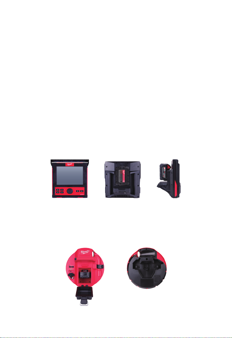
1 Introduction
1. Introduction
1.1 Le SYSTÈME D’INSPECTION DE TUYAUX M18™
Les systèmes comprennent trois modules principaux, l’ÉCRAN SANS FIL M18™, le
CENTRE DE COMMANDE 500 GB M18™ et les DÉVIDOIRS D’INSPECTION DE TUYAUX.
1.2 Survol de l’ÉCRAN SANS FIL M18™
L’ÉCRAN SANS FIL M18™ permet de visualiser la vidéo brute prise par la tête de caméra,
en enregistrant de vidéos et en capturant d’images ainsi que de fonctions de relecture de
chiers vidéo et image. Durant l’enregistrement de vidéos, c’est possible de capturer les
commentaires audio à l’aide du microphone interne tandis que les commentaires texte
peuvent être ajoutés à l’aide de l’option d’étiquettes. Ces commentaires texte seront
affichés sur la vidéo enregistrée et seront montrés sur les images, accompagnés par
l’heure et la date du système ainsi que la distance du câble poussant déployé.
Veuillez noter que l’ÉCRAN SANS FIL ou la tablette ayant l’appli d’inspection de tuyaux
Milwaukee® doivent être connectés au CENTRE DE COMMANDE DE 500 GB M18™ an
de créer d’enregistrements vidéo ou image. Les chiers vidéo et image seront enregistrés
dans le DISQUE INTERNE DU CENTRE DE COMMANDE ou bien, LE DISQUE FLASH
DU CENTRE DE COMMANDE.
Vue avant Vue de derrière Vue de côté
1.3 Survol du CENTRE DE COMMANDE DE 500 GB M18™
Le CENTRE DE COMMANDE DE 500 GB M18™ est le cerveau du SYSTÈME D’INSPECTION
DE TUYAUX. L’ÉCRAN SANS FIL ou la tablette ayant l’appli d’inspection de tuyaux Milwaukee®
se relient au CENTRE DE COMMANDE an de recevoir les enregistrements vidéo et image crées.
Tous les deux sont enregistrés dans le DISQUE INTERNE DU CENTRE DE COMMANDE.
Vue avant Vue de derrière
15
Page 90
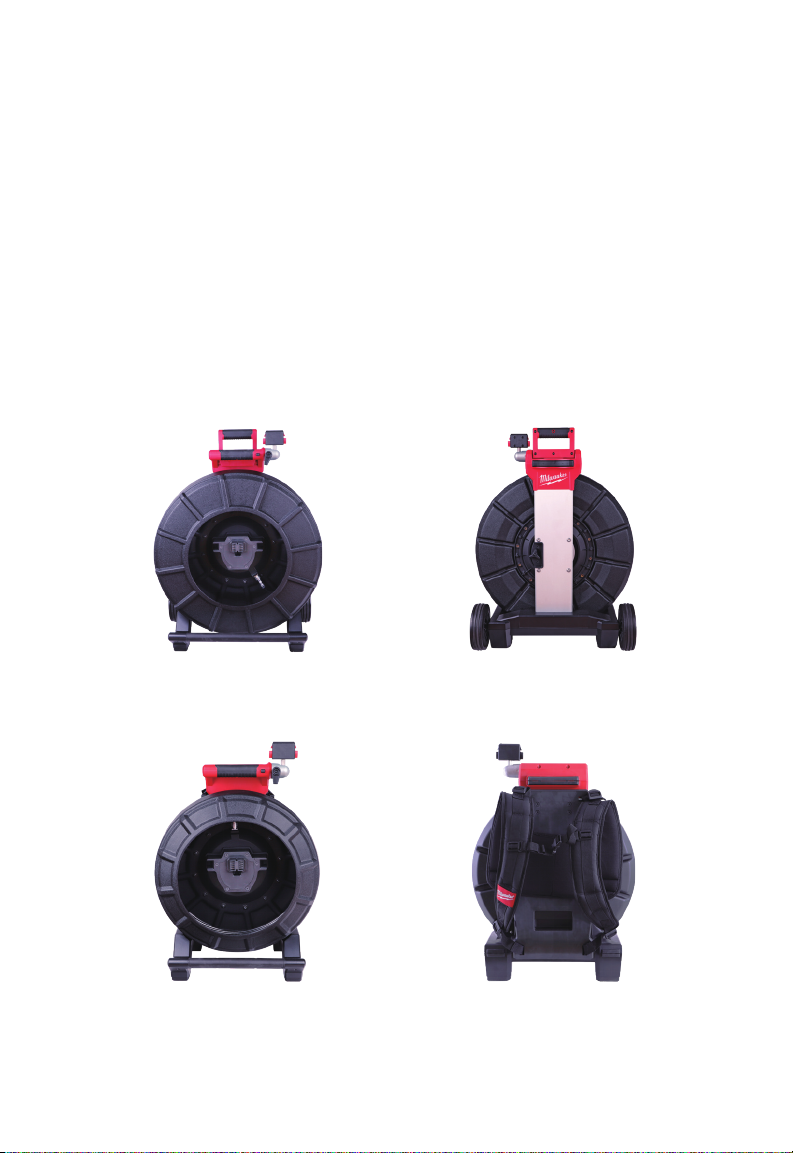
1 Introduction
1.4 Survol du DÉVIDOIR D’INSPECTION DE TUYAUX
Le DÉVIDOIR D’INSPECTION DE TUYAUX garde et contrôle le déploiement du câble
poussant. Les dévidoirs sont disponibles en deux dimensions : le dévidoir de 36,5 M (120’)
est utilisé, la plupart du temps, dans de tuyaux de 50,80 mm (2") à 152,40 mm (6") tandis
que le dévidoir le plus large de 60,9M (200’) est utilisé pour les tuyaux dont la taille est
d’entre de 76,20 mm (3") et 254 mm (10").
Les deux dimensions comprennent un câble poussant avec un assemblage de ressort qui
sert en tant que base de montage pour la tête de caméra de mise à niveau automatique.
l’ÉCRAN SANS FIL M18™ et le CENTRE DE COMMANDE DE 500 GB M18™ fonctionneront
bien avec les deux dimensions.
C’est possible d’employer les deux dimensions d’une position verticale (debout) ou
horizontale (de côté). Le dévidoir de 36,5M (120’) est muni d’une plaque de montage
dans la partie arrière, ce qui sert à attacher les sangles à sac à dos.
Survol du DÉVIDOIR D’INSPECTION DE TUYAUX DE 60,9 M (200')
Vue avant Vue de derrière
Survol du DÉVIDOIR D’INSPECTION DE TUYAUX DE 36,5 M (120')
Vue avant Vue de derrière
16
Page 91
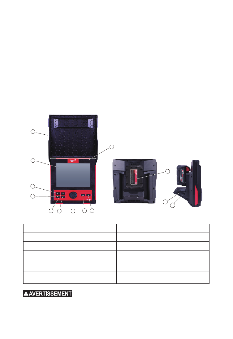
2 ÉCRAN SANS FIL M18™
2. ÉCRAN SANS FIL M18™
2.1 Survol de l’ÉCRAN SANS FIL M18™
L’ÉCRAN SANS FIL M18™ comporte de fonctions de visualisation, d’enregistrement et
de relecture de chiers vidéo et image. Durant l’enregistrement de vidéos, c’est possible
de capturer les commentaires audio à l’aide du microphone interne tandis que les
commentaires texte peuvent être ajoutés à l’aide de l’option ÉTIQUETTE.
Veuillez noter que l’ÉCRAN SANS FIL ou la tablette ayant l’appli d’inspection de tuyaux
Milwaukee® doivent être connectés au CENTRE DE COMMANDE DE 500 GB M18™
afin de créer d’enregistrements vidéo ou image. Les fichiers vidéo et image seront
enregistrés dans le DISQUE INTERNE DU CENTRE DE COMMANDE.
1
10
2
11
3
4
5
6 7
8 9
12a
12b
1. Pare-soleil 7. Cadran de navigation
2. Afcheur ACL 8. Bouton d’enregistrement vidéo
3. Bouton d'alimentation 9. Bouton d’enregistrement image
4. Bouton « Retour » 10. Microphone interne
5. Bouton de rétablissement à distance 11.
6. Bouton de microphone 12.
Aire de montage pour BLOC-PILES
M18™
12a Port USB-A
12b Port USB-C
Afin de minimiser le risque de blessures, au moment où
vous posez l’outil ou le bloc-piles, ne pas laisser le bloc-piles entrer en contact
avec de uides conductifs ou corrosifs.
17
Page 92

2 ÉCRAN SANS FIL M18™
2.2 Déploiement de l’ÉCRAN SANS FIL M18™
La présente section comprend la configuration des fonctions et d’options disponibles
sur l’ÉCRAN SANS FIL M18™. Le montage de l’ÉCRAN SANS FIL sur le DÉVIDOIR
D’INSPECTION DE TUYAUX se trouve dans la section 4.4 de ce manuel.
2.2.1 Marche/Arrêt
Appuyer sur le bouton d’alimentation qui se trouve sur l’ÉCRAN SANS FIL M18™.
Les boutons et le cadran de navigation seront illuminés, ce qui indiquera que l’outil a été
mis en marche. L’icône de l’ÉCRAN SANS FIL apparaîtra sur la barre d’état de l’afcheur
ACL, à part de l’état d’autonomie de la batterie.
2.2.2 Conguration initiale de l’ÉCRAN SANS FIL M18™
Tous les paramètres sont enregistrés dans la mémoire de l’ÉCRAN SANS FIL M18™ et
vont y rester sauf s’ils sont changés. Veuillez noter que les paramètres seront perdus
si l’unité est rétablie à ses paramètres d’usine ou bien, lors du formatage du DISQUE
INTERNE DU CENTRE DE COMMANDE DE 500 GB M18™. Il n’est pas nécessaire de
connecter le DÉVIDOIR D’INSPECTION DE TUYAUX à caméra durant la conguration
initiale.
Ces paramètres initiaux de l’ÉCRAN SANS FIL définiront les UNITÉS de mesure de
distance, les formats d’affichage de DATE et HEURE, les fréquences de SONDE, la
qualité de VIDÉO et IMAGE, les PARAMÈTRES DE CONNEXION et de LANGUE.
C’est aussi possible de définir ces paramètres-ci depuis la tablette ayant l’appli
d’inspection de tuyaux Milwaukee®.
2.2.3 Navigation dans le menu de Paramètres
Cadran de navigation.- Tourner le cadran de navigation à droite ou à
gauche pour naviguer entres les menus. Lorsque vous tournez le cadran
de navigation, la position/les éléments de menu seront mis en lumière par
la ligne rouge de curseur.
Appuyer sur le cadran de navigation an de sélectionner et de conrmer les
options du menu de paramètres.
Bouton de retour.- Appuyer sur le bouton de retour en étant dans n’importe
quel menu ou sub-menu pour retourner au menu précédent. Appuyer sur
le bouton de retour plusieurs fois pour retourner à l’écran de visualisation
principale.
18
Page 93
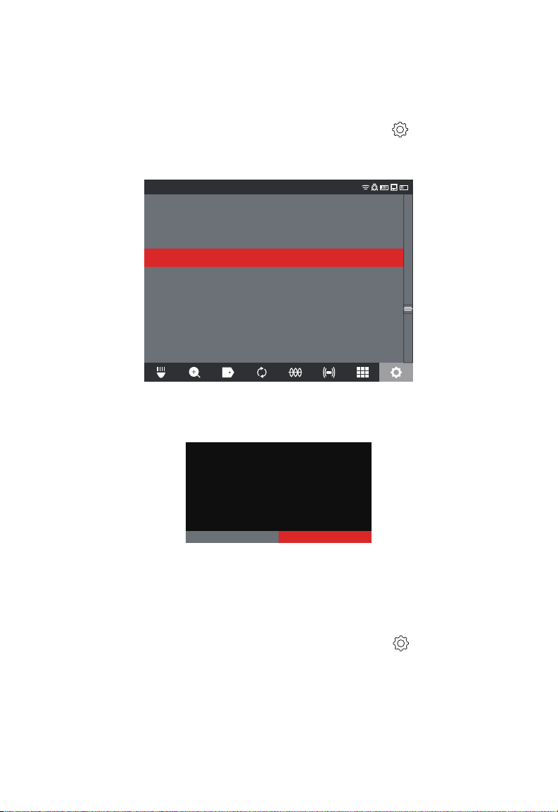
2 ÉCRAN SANS FIL M18™
ANNULER OK
2.2.4 Ajustage des paramètres de LANGUE de l’ÉCRAN SANS FIL
M18™
Il est conseillé d’abord d’ajuster l’outil dans votre propre LANGUE pour que vous puissiez
bien lire et comprendre tous les menus.
1. Tourner le cadran de navigation vers l’option PARAMÈTRES et appuyer sur le
cadran de navigation.
2. Tourner le cadran de navigation vers l’option LANGUE et appuyer sur le cadran pour
entrer au sub-menu LANGUE.
PARAMÈTRES
PARAMÈTRES DE L’ÉCRAN
DATE ET HEURE
UNITÉS
Pieds
LANGUE
Français
MANAGE JOBS
2019/05/10 6 FILES
MISE À JOUR DU SYSTÈME
RÉINITIALISATION D’USINE
À PROPOS
SERVICE APRÈS-VENTE
3. Tourner le cadran de navigation pour choisir la LANGUE désirée et appuyer sur le
cadran.
4. Tourner le cadran de navigation et appuyer sur l’option « OK » pour changer la LANGUE.
La langue du moniteur sans fil a été modifiée.
Ces modifications ne prendront effet qu’après
le redémarrage de l’appareil.
SETTINGS
5. Le système se réinitialisera et redémarrera dans la LANGUE choisie.
2.2.5 Ajustage de la DATE et l’HEURE
Le système offre les FORMATS DE DATE de MM/DD/YYYY, DD/MM/YYYY et YYYY/
MM/DD avec les FORMATS D’HEURE de 12 heures et de 24 heures.
1. Tourner le cadran de navigation vers l’option PARAMÈTRES
cadran.
2. Tourner le cadran de navigation vers l’option DATE ET HEURE et appuyer sur le
cadran pour entrer au sub-menu DATE ET HEURE.
3. Tourner le cadran de navigation vers l’option FORMAT DE LA DATE et appuyer sur le
cadran. Utiliser le cadran de navigation pour choisir le FORMAT DE LA DATE désiré et
appuyer sur le cadran pour accepter le changement. Répéter les mêmes étapes pour
la sélection du FORMAT DE L’HEURE.
19
et appuyer sur le
Page 94
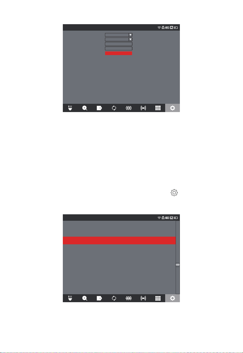
2 ÉCRAN SANS FIL M18™
PARAMÈTRES
FORMAT DE LA DATE
FORMAT DE L’HEURE
RÉGLAGE DE LA DATE
RÉGLAGE DE L’HEURE
YYYY/MM/DD
24 HOUR
2019 / 10 / 23
16 : 04 : 35
ENREGISTRER
4. Il faut utiliser le cadran de navigation maintenant pour entrer les valeurs de DATE et
HEURE.
5. Tourner le cadran de navigation vers l’option ENREGISTRER et appuyer sur le
cadran.
La DATE et l’HEURE sont dénies maintenant et vous serez maintenant retourné vers le
menu PARAMÈTRES.
Si vous utilisez une tablette ayant l’appli d’inspection de tuyaux Milwaukee®, la DATE et
l’HEURE seront prises depuis la tablette.
2.2.6 Ajustage des UNITÉS de mesure
1. Tourner le cadran de navigation vers l’option PARAMÈTRES et appuyer sur le
cadran.
2. Tourner le cadran de navigation vers l’option UNITÉS et appuyer sur le cadran pour
entrer au sub-menu.
PARAMÈTRES
PARAMÈTRES DE L’ÉCRAN
DATE ET HEURE
UNITÉS
Pieds
LANGUE
Français
2019/05/10 6 FILES
MISE À JOUR DU SYSTÈME
RÉINITIALISATION D’USINE
À PROPOS
SERVICE APRÈS-VENTE
3. Tourner le cadran de navigation pour choisir entre « Pieds » et « Mètre » et appuyer
sur le cadran.
20
Page 95
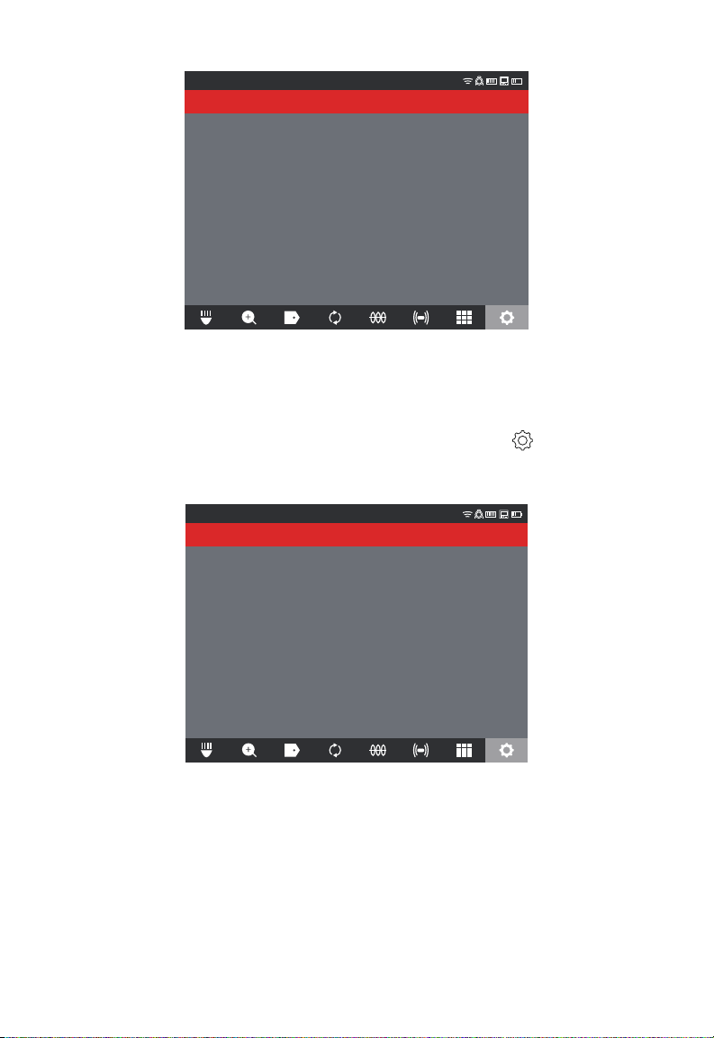
2 ÉCRAN SANS FIL M18™
PARAMÈTRES
Pieds
Mètre
Les UNITÉS de mesure sont dénies maintenant et vous serez maintenant retourné vers
le menu PARAMÈTRES.
2.2.7 Ajustage de la FRÉQUENCE LA SONDE
1. Tourner le cadran de navigation vers l’option PARAMÈTRES , appuyer sur le
cadran.
2. Tourner le cadran de navigation vers l’option FRÉQUENCE LA SONDE et appuyer sur
le cadran pour entrer au sub-menu.
PARAMÈTRES
512Hz
640Hz
33kHz
3. Tourner le cadran de navigation pour choisir la fréquence de sonde désirée entre 512
Hz, 640 Hz ou 33 kHz et après, appuyer sur le cadran. La fréquence de sonde est
choisie maintenant et vous serez retourné au sub-menu de paramètres.
21
Page 96
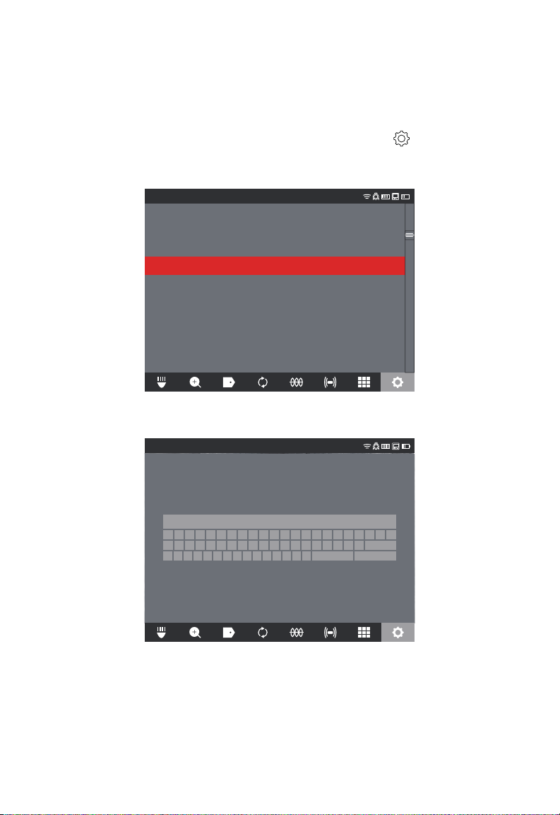
2 ÉCRAN SANS FIL M18™
2.2.8 Ajustage le NOM DE LA COMPAGNIE
Cette option enregistre le NOM DE LA COMPAGNIE dans la mémoire du système. Le
NOM DE LA COMPAGNIE giclera sur les premières 5 secondes de la vidéo et sera
afché dans toutes les images JPEG.
1. Tourner le cadran de navigation vers l’option PARAMÈTRES et appuyer sur le
cadran.
2. Tourner le cadran de navigation vers l’option NOM DE LA COMPAGNIE et appuyer
sur le cadran pour entrer au sub-menu.
PARAMÈTRES
GÉRER LES TÂCHES
FRÉQUENCE DE LA SONDE
640Hz
PARAMÈTRES DE L’ÉTIQUETTE
MANAGE JOBS
2019/05/10 6 FILES
NOM DE LA COMPAGNIE
PARAMÈTRES DE LA VIDÉO
1080P 30FPS
PARAMÈTRES DE L’IMAGERIE
1920x1080
FORMATER LE DISQUE
PARAMÈTRES DE CONNEXION
MTCAM_02938B284
PARAMÈTRES DE LA CAMÉRA
3. Utiliser le cadran de navigation pour utiliser le clavier digital en appuyant sur lui an
d’accepter chacun des caractères du clavier.
PARAMÈTRES
A À Â Æ B C Ç D E É È Ê Ë F G H I Î J
N O Ô Œ P Q R S T U Ù Û Ü V W X Y Ÿ Z
1 2 3 4 5 6 7 8 9 . -, ?
MILWAUKEE
0
SUPPRIMER ACCEPTER
!
K L M
ESPACE
4. Lorsque vous avez ni avec le NOM DE LA COMPAGNIE, naviguer vers la touche «
ACCEPTER » et appuyer sur le cadran de navigation.
5. Choisir l’option SAUVEGARDER ou annuler pour continuer.
22
Page 97
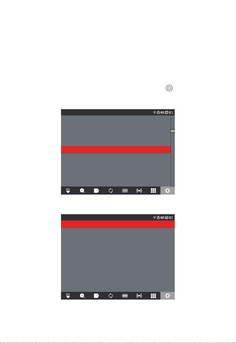
2 ÉCRAN SANS FIL M18™
2.2.9 PARAMÈTRES de LA VIDÉO et L'IMAGERIE
PARAMÈTRES DE LA VIDÉO
Cette option de paramètres vous permettra de choisir la résolution de vidéo. La résolution
affectera la qualité de la vidéo, ce qui affectera la taille du chier vidéo. Les choix de
résolution et d’images par seconde (i/s) sont :
Options de PARAMÈTRES DE LA VIDÉO : 1080p avec 30 images par second ou 15
images par second, 720p avec 30 images par second ou 15 images par second ou 480p
avec 30 images par second ou 15 images par second.
1. Tourner le cadran de navigation vers l’option PARAMÈTRES
et appuyer sur le
cadran.
2. Tourner le cadran de navigation vers l’option PARAMÈTRES DE LA VIDÉO et
appuyer sur le cadran pour entrer au sub-menu.
PARAMÈTRES
GÉRER LES TÂCHES
FRÉQUENCE DE LA SONDE
640Hz
PARAMÈTRES DE L’ÉTIQUETTE
MANAGE JOBS
2019/05/10 6 FILES
NOM DE LA COMPAGNIE
MILWAUKEE
PARAMÈTRES DE LA VIDÉO
1080P 30FPS
PARAMÈTRES DE L’IMAGERIE
1920x1080
FORMATER LE DISQUE
PARAMÈTRES DE CONNEXION
MTCAM_02938B284
PARAMÈTRES DE LA CAMÉRA
3. Utiliser le cadran de navigation pour passer entre tous les choix de résolution: 1080p,
720p ou 480p et après, appuyer sur le cadran.
PARAMÈTRES
1080p
720p
480p
23
Page 98
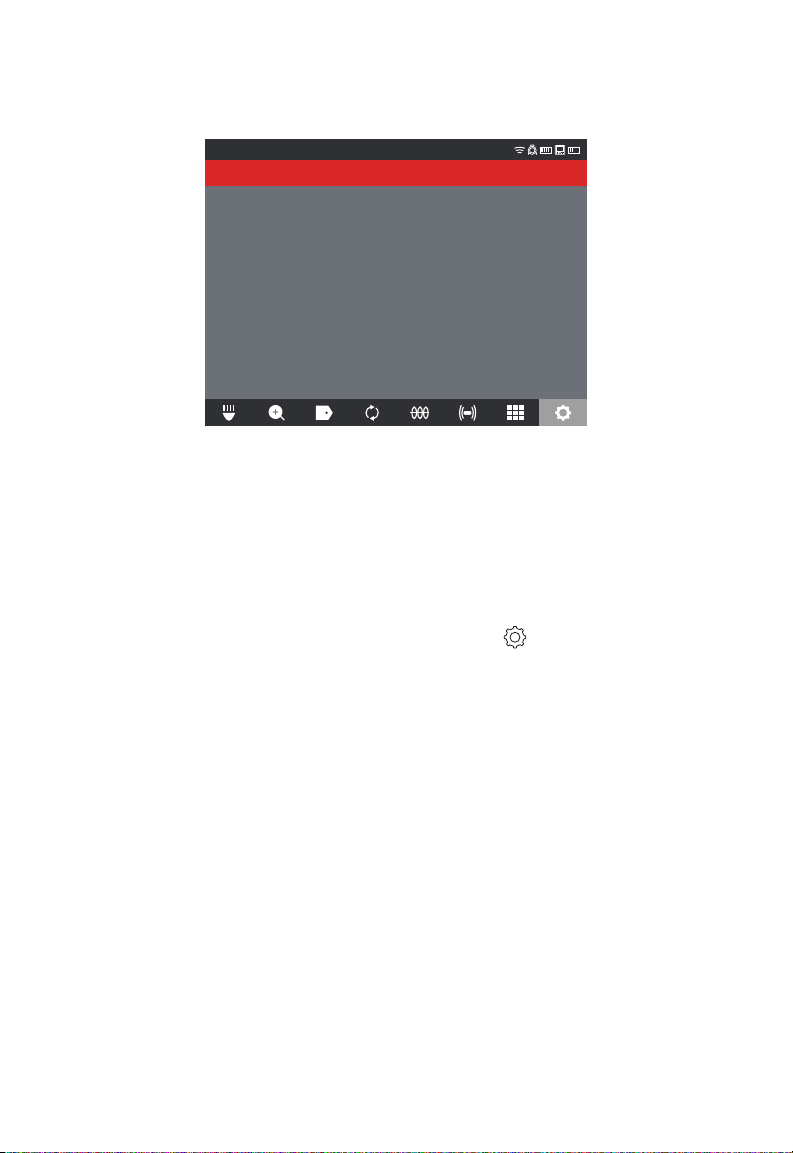
2 ÉCRAN SANS FIL M18™
4. Une fois choisie la résolution de 1080p, 720p ou 480p, le prochain écran vous
demandera de sélectionner entre 30 images par seconde ou 15 images par second;
faire votre choix et appuyer sur le cadran de navigation.
PARAMÈTRES
30FPS
15FPS
5. Après avoir choisie la quantité d’images par seconde, le système vous retournera vers
le menu de PARAMÈTRES.
PARAMÈTRES DE L'IMAGERIE
Cette option de paramètres vous permettra de choisir les dimensions de l’IMAGE de la
vidéo. Ces dimensions affecteront la qualité de l’image, ce qui affectera la taille du chier
image.
Options de paramètres d’image : 1920 x 1080, 1280 x 720 ou 640 x 480
Tourner le cadran de navigation vers l’option PARAMÈTRES et appuyer sur le cadran.
Tourner le cadran de navigation vers l’option PARAMÈTRES DE L'IMAGERIE et appuyer
sur le cadran pour entrer au sub-menu.
Utiliser le cadran de navigation pour passer entre tous les choix de dimensions,
sélectionner 1920 x 1080, 1280 x 720 ou 640 x 480 et appuyer sur le cadran de navigation.
Après avoir choisie l’option de paramètres DE L'IMAGERIE désirée, le système vous
retournera vers le menu de PARAMÈTRES.
2.2.10 PARAMÈTRES DE CONNEXION
La méthode de connexion préétablie pour l’ÉCRAN SANS FIL M18™ et le CENTRE DE
COMMANDE DE 500 GB M18™ est à travers connexion WiFi. La portée sans l entre les
deux unités est de 152,4 m (500’). Si un CENTRE DE COMMANDE actif est auprès de la
portée de 152,4 m (500’), il sera montré dans la liste du hub de contrôle. C’est possible
de relier l’ÉCRAN SANS FIL et le CENTRE DE COMMANDE à l’aide d’un câble d’USB-C
en tant que back-up.
Premier appairage de l’ÉCRAN SANS FIL
• S’il n’y a qu’un seule CENTRE DE COMMANDE à portée, l’ÉCRAN SANS FIL arrêtera
automatiquement l’appairage sans exiger aucune interaction de la part de l’utilisateur.
• S’il y a plus d’un CENTRE DE COMMANDE à portée, la liste de hubs de contrôle
s’affichera sur l’ÉCRAN SANS FIL ou bien, sur l’appli d’inspection de tuyaux
Milwaukee® pour que l’utilisateur puisse choisir le CENTRE DE COMMANDE désiré.
24
Page 99
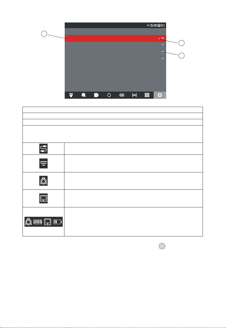
2 ÉCRAN SANS FIL M18™
PARAMÈTRES
a
Liste des centres de contrôle
MTCAM_02938B284
MTCAM_029384BEA
MTCAM_02938ED7A
MTCAM_029383A7E
b
c
Liste de centres de commande
a. Liste de CENTRES DE COMMANDE à proximité avec WiFi activé
b. Statut.- Une marque indique qu’il est connecté
c. Puissance de signal des CENTRES DE COMMANDE ayant le WiFi activé
Autonomie de la pile.- Les deux icônes du BLOC-PILES M18™ BATTERY ont quatre
segments par icône. Chacun d’eux représente 25 % de l’autonomie de la pile. Un
avertissement de charge faible s’afchera lorsque l’autonomie est auprès 10 %
Icône de connexion de câble. Indique que l’ÉCRAN SANS FIL et le
CENTRE DE COMMANDE sont reliés à l’aide d’un câble USB-C.
État de la connexion du CENTRE DE COMMANDE et puissance
de signal sans l. Cette icône s’afchera lorsque le CENTRE DE
COMMANDE est connecté à l’ÉCRAN SANS FIL à travers du WiFi.
Icône de DÉVIDOIR D’INSPECTION DE TUYAUX.- S’affichera
lorsque l’ÉCRAN SANS FIL et le CENTRE DE COMMANDE sont
connectés à l’aide du WIFI ou d’un câble USB-C.
Icône d’ÉCRAN SANS FIL.- S’affichera lorsque l’ÉCRAN SANS
FIL et le CENTRE DE COMMANDE sont connectés à l’aide de
WiFi ou d’un câble de USB-C.
Icône de statut de PILE M18™.- Deux icônes de pile s’afcheront à
part de l’icône de l’ÉCRAN SANS FIL. L’icône de la pile à gauche
de l’icône de l’écran représente le CENTRE DE COMMANDE.
L’icône du bloc-piles à droite de l’icône de l’écran représente
l’ÉCRAN SANS FIL.
1. Tourner le cadran de navigation vers l’option PARAMÈTRES
et appuyer sur le
cadran.
2. Tourner le cadran de navigation vers l’option PARAMÈTRES DE CONNEXION et
appuyer sur le cadran pour entrer au sub-menu.
25
Page 100
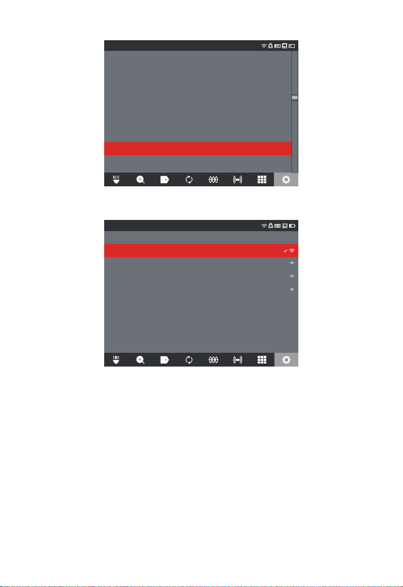
2 ÉCRAN SANS FIL M18™
PARAMÈTRES
GÉRER LES TÂCHES
FRÉQUENCE DE LA SONDE
640Hz
PARAMÈTRES DE L’ÉTIQUETTE
MANAGE JOBS
2019/05/10 6 FILES
NOM DE LA COMPAGNIE
MILWAUKEE
PARAMÈTRES DE LA VIDÉO
1080P 30FPS
PARAMÈTRES DE L’IMAGERIE
1920x1080
FORMATER LE DISQUE
PARAMÈTRES DE CONNEXION
MTCAM_02938B284
PARAMÈTRES DE LA CAMÉRA
3. Utiliser le cadran de navigation pour choisir le CENTRE DE COMMANDE disponible
désiré et après, appuyer sur le cadran pour entreprendre la connexion.
PARAMÈTRES
Liste des centres de contrôle
MTCAM_02938B284
MTCAM_029384BEA
MTCAM_02938ED7A
MTCAM_029383A7E
4. Après avoir choisi le CENTRE DE COMMANDE, vous serez retourné au menu
principal. Le nom du CENTRE DE COMMANDE sera afché dans la barre de menu
sous les PARAMÈTRES DE CONNEXION.
26
 Loading...