

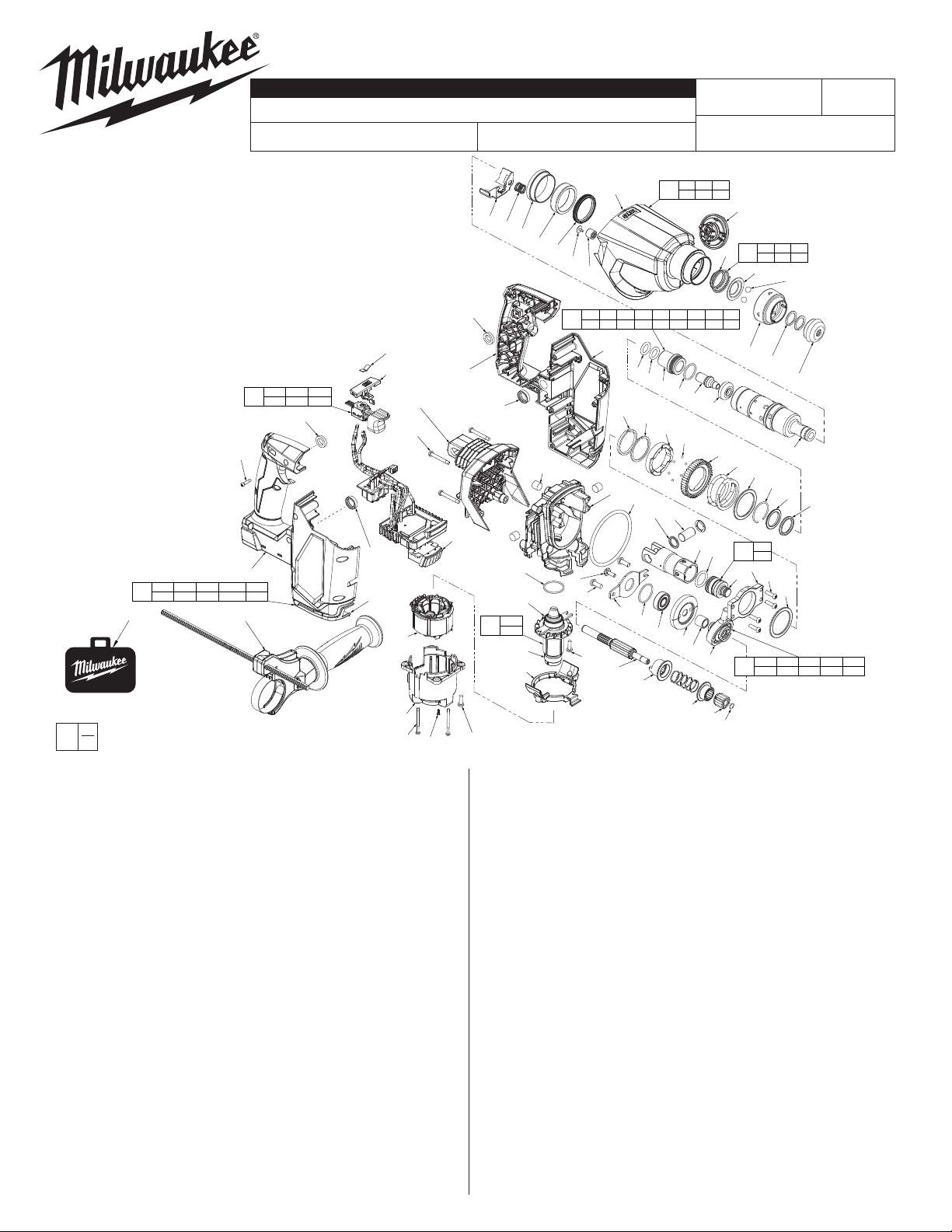
SERVICE PARTS LIST
SPECIFY CATALOG NO. AND SERIAL NO. WHEN ORDERING PARTS
M18™ FUEL™ 1" SDS Plus Rotary Hammer
CATALOG NO. 2912-20
FIG. PART NO. DESCRIPTION OF PART NO. REQ.
1 42-76-0068 SDS Head Service Kit 1
1-1 42-52-5262 Dust Cap 1
1-2 44-90-0014 C-Ring 2
1-3 42-76-0066 Chuck Sleeve 1
1-4 02-02-0275 7mm Ball 2
1-5 42-36-0191 Ball Plate 1
1-6 40-50-5262 Spring 1
2 31-40-0012 Front Housing Assembly 1
2-1 --------------- Front Housing 1
2-2 --------------- Spring Seal 1
2-3 --------------- Front bushing Spindle 1
2-4 --------------- Bushing Spacer Spindle 1
2-5 --------------- M2.3 x 6mm ST T-8 Screw 1
2-6 --------------- Needle Bearing 1
3 44-90-1001 Locking Plate 1
4 40-50-0870 Spring 1
5 44-10-0062 Selector Knob Assembly 1
6 45-22-0092 SDS Spindle Sleeve Assembly 1
28-1 28-2 28-3
28
28-4 28-5 28-6
30-4
30-9
x11
30-1 30-2 30-4 30-5 30-6
30
30-7 30-8 30-9 30-10
33
EXAMPLE:
00
Component Parts (Small #) Are Included
0
When Ordering The Assembly (Large #).
FIG. PART NO. DESCRIPTION OF PART NO. REQ.
6-1 38-50-0081 Spindle 1
6-2 43-06-0026 Brake Ring 1
6-3 45-08-0042 Anvil 1
6-4 34-40-0192 O-Ring 1
6-5 45-22-0088 Anvil Sleeve 1
6-6 34-40-0193 O-Ring 1
6-7 34-40-0194 Back Pressure Ring 1
6-8 34-40-0197 Bumper Ring 1
6-9 42-76-0067 Washer 1
6-10 44-90-0101 Snap Ring 1
6-11 45-88-0207 Thrust Washer 1
6-12 40-50-0183 M-Clutch Spring 1
6-13 32-75-0028 Gear 1
6-14 02-02-0111 2.5mm Ball 6
6-15 42-70-0138 Clutch Plate 1
6-16 44-90-0102 Retaining Ring 1
6-17 44-90-0103 Snap Ring 1
7 45-88-0208 Washer 1
8 42-36-0126 Bearing 1
9 45-56-0026 Striker / O-Ring Assembly 1
9-1 --------------- Striker 1
9-2 34-40-1511 O-Ring 1
10 44-62-0033 Piston 1
11 44-60-0176 Wrist Pin 1
12 44-60-0033 Wrist Pin Washer 2
13 43-44-1375 Gasket 1
14 05-81-1337 M4 x 0.7mm Machine Screw 8
15 31-15-0079 Gearcase 1
16 43-84-0300 Felt Plug 3
17 02-04-0156 Ball Bearing 1
19 45-88-0209 Washer 1
20 05-81-0196 M4 x 12mm Screw 1
21 42-92-0087 Bearing Retainer 1
22 05-78-0032 M5 x 13mm Mach. Screw 2
23 31-44-0238 Rear Housing Assembly 1
24 05-88-1525 M4 ST Screw 4
25 36-92-0013 Wobble Shaft Assembly 1
30-7
31
30-6
30-2
30-10
30-5
28-2
28-3
28-4
x2
23
24
x4
28-5
x4
BULLETIN NO.
REVISED BULLETIN
STARTING
SERIAL
3
4
2-4
2-3
2-2
30-4
30-8
30-6
16 x3
29
26
27-3
27-3
27
27-8
27-8
28-1
14
FIG. PART NO. DESCRIPTION OF PART NO. REQ.
x4
25-1 44-90-1180 C-Ring 1
25-2 32-60-0021 Second Pinion 1
25-3 45-22-0089 Coupler 1
25-4 44-50-0101 Mode Select Spring 1
25-5 45-22-0091 Wobble Bearing Coupler 1
25-6 33-66-0101 I-Shaft 1
25-7 36-92-0012 Wobble Bearing 1
25-8 45-36-1826 Spacer 1
25-9 --------------- Ist Bevel Gear 1
26 34-40-0201 O-Ring 2
27 16-01-0117 Rotor Assembly 1
27-3 --------------- Ball Bearing 1
27-6 05-81-0266 M4 x 8mm M Screw w/ Nylock 2
27-8 --------------- Ball Bearing 1
28 14-20-0351 PCBA /Motor/Stator Assembly 1
28-1 31-86-0012 Clamp Spacer 1
28-2 --------------- Stator 1
28-3 31-50-0066 Motor Housing 1
28-4 06-82-2367 M3 x 1.058 Pan Hd. T-10 Screw 2
28-5 --------------- M2 x 0.89 PT Screw 4
29 42-28-2712 Terminal Cover 1
30 31-44-0237 Handle Housing Kit 1
30-1 --------------- Housing-Support 1
30-2 --------------- Housing-Cover 1
30-4 42-40-0051 Foam Bushing 2
30-5 45-24-0072 Shuttle 1
30-6 44-52-0081 Rubber Cushion 2
30-7 --------------- Handle Cover 1
30-8 --------------- Handle Support 1
30-9 06-82-1080 M3 ST Screw 11
30-10 --------------- Spring 1
31 31-44-0208 Side Handle Assembly 1
32 12-20-0328 Service Nameplate (Not shown) 1
33 42-55-0171 Blow Molded Case (Hammer w/ 2 Batteries) 1
42-55-0173
L85A
6-17
12 x2
26
6-6
6-5
17
25-4
2
6-4
6-15
11
25-9
25-3
2-1 2-2 2-3
2-4 2-5 2-6
6-14 (x6)
25-8
2-1
2-5
2-6
6-1 6-2 6-3 6-4 6-5 6-6 6-7 6-8 6-9
6
6-10 6-11 6-12 6-13 6-14 6-15 6-16 6-17
30-1
6-7
6-16
15
13
20
22 x2
21
27-6
x2
25-6
25-5
Blow Molded Case (Hammer, DDE w/ 2 Batteries)
MILWAUKEE TOOL l www.milwaukeetool.com
13135 W. LISBON RD., BROOKFIELD, WI 53005
WIRING INSTRUCTION
SEE PAGE 6
5
1-1 1-2 1-3
1-6
1
1-4 1-5 1-6
1-5
1-3
1-2
x2
6-3
6-2
6-13
6-12
6-11
6-10
10
25-7
25-2
25-1
9-1
9-2
9
9-2
8
9-1
14 x4
25-1 25-2 25-3 25-4 25-5
25
25-6 25-7 25-8 25-9 27
1-4
x2
1-1
6-1
6-9
7
54-24-2725
DATE
Jan. 2022
6-8
1
Drwg. 2
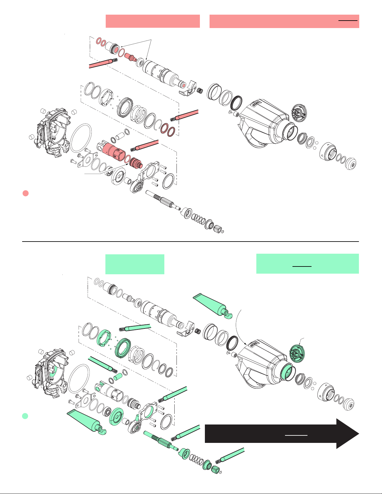
LUBRICATION NOTES:
Apply a very light coat of
*
grease to the inside wall of
piston. No grease to inside
base of cavity.
No grease to the
face of ram.
Type GE 00 Urethyn Grease
No. 49-08-5355, 2.8 oz./80g tube
Coat the inside cavity
of the sleeve and spindle
with GE 00 grease.
*
NOTE: The entire contents of the grease tube will not
be used. Use a total of appoximately .32 oz./9.2g.
Lightly coat all parts
highlighted here with GE 00 grease
unless directed otherwise.
LUBRICATION NOTES:
Place approx.
38.4 grams,
(1.3 oz.) of ‘B118’
grease in the
crankcase,
between the
bevel gear and the
wobble plate.
*
Type ‘B118’ Grease
No. 45-00-0230,
1.75 oz./50g tube
NOTE: The entire contents of the
grease tube will not be used. Use a
total of appoximately 3.06 oz./86.7g.
Place approx. 38.4 grams,
(1.3 oz.) of ‘B118’ grease in the
gear cavity of the gearcase.
Coat Shift Lever (5) with
grease.
Prior to reinstalling,
clean gear assemblies
with a clean, dry cloth.
Lightly coat all parts highlighted here
with ‘B118’ grease. Apply a greater amount
of grease to all internal and external gear teeth.
Place a very liberal
*
amount of grease to
the rear of the piston.
SERVICE NOTES on pages 3, 4 and 5 are included for
general servicing of the tool and ARE NOT complete
step by step instructions.
 Loading...