


OPERATOR'S MANUAL
MANUEL de L'UTILISATEUR
MANUAL del OPERADOR
Cat. No. / No de cat.
2736-20
M18 FUEL™ 8 1/4" TABLE SAW W/ ONE-KEY™
SCIE A TABLE DE 210 mm (8 1/4") M18 FUEL™
AVEC ONE-KEY™
SIERRA DE MESA DE 210 mm (8 1/4") M18 FUEL™
CON ONE-KEY™
WARNING To reduce the risk of injury, user must read and understand operator's manual.
AVERTISSEMENT An de réduire le risque de blessures, l'utilisateur doit lire et bien
comprendre le manuel.
ADVERTENCIA Para reducir el riesgo de lesiones, el usuario debe leer y entender el manual.

GENERAL POWER TOOL
WARNING
SAFETY WARNINGS
Read all safety warnings, instruc-
tions provided with this power tool. Failure to
follow all instructions listed below may result in
electric shock, re and/or serious injury. Save all
warnings and instructions for future reference.
The term "power tool" in the warnings refers to your
mains-operated (corded) power tool or battery-oper-
ated (cordless) power tool.
tions, illustrations and specica-
WORK AREA SAFETY
• Keep work area clean and well lit. Cluttered or
dark areas invite accidents.
• Do not operate power tools in explosive atmo-
spheres, such as in the presence of ammable
liquids, gases or dust. Power tools create sparks
which may ignite the dust or fumes.
• Keep children and bystanders away while operat-
ing a power tool. Distractions can cause you to lose
control.
ELECTRICAL SAFETY
• Power tool plugs must match the outlet. Never
modify the plug in any way. Do not use any
adapter plugs with earthed (grounded) power
tools. Unmodied plugs and matching outlets will
reduce risk of electric shock.
• Avoid body contact with earthed or grounded
surfaces, such as pipes, radiators, ranges and
refrigerators. There is an increased risk of electric
shock if your body is earthed or grounded.
• Do not expose power tools to rain or wet conditions. Water entering a power tool will increase the
risk of electric shock.
• Do not abuse the cord. Never use the cord for
carrying, pulling or unplugging the power tool.
Keep cord away from heat, oil, sharp edges or
moving parts. Damaged or entangled cords increase
the risk of electric shock.
• When operating a power tool outdoors, use an
extension cord suitable for outdoor use. Use of
a cord suitable for outdoor use reduces the risk of
electric shock.
• If operating a power tool in a damp location is
unavoidable, use a ground fault circuit interrupter
(GFCI) protected supply. Use of an GFCI reduces
the risk of electric shock.
PERSONAL SAFETY
• Stay alert, watch what you are doing and use
common sense when operating a power tool. Do
not use a power tool while you are tired or under
the inuence of drugs, alcohol or medication. A
moment of inattention while operating power tools
may result in serious personal injury.
• Use personal protective equipment. Always
wear eye protection. Protective equipment such
as a dust mask, non-skid safety shoes, hard hat or
hearing protection used for appropriate conditions
will reduce personal injuries.
• Prevent unintentional starting. Ensure the switch
is in the o-position before connecting to power
source and/or battery pack, picking up or carrying
the tool. Carrying power tools with your nger on
the switch or energizing power tools that have the
switch on invites accidents.
• Remove any adjusting key or wrench before
turning the power tool on. A wrench or a key left
attached to a rotating part of the power tool may
result in personal injury.
• Do not overreach. Keep proper footing and
balance at all times. This enables better control
of the power tool in unexpected situations.
• Dress properly. Do not wear loose clothing or
jewelry. Keep your hair and clothing away from
moving parts. Loose clothes, jewelry or long hair
can be caught in moving parts.
• If devices are provided for the connection of
dust extraction and collection facilities, ensure
these are connected and properly used. Use of
dust collection can reduce dust-related hazards.
• Do not let familiarity gained from frequent use
of tools allow you to become complacent and
ignore tool safety principles. A careless action can
cause severe injury within a fraction of a second.
POWER TOOL USE AND CARE
• Do not force the power tool. Use the correct power
tool for your application. The correct power tool
will do the job better and safer at the rate for which
it was designed.
• Do not use the power tool if the switch does not
turn it on and o. Any power tool that cannot be
controlled with the switch is dangerous and must be
repaired.
• Disconnect the plug from the power source and/
or remove the battery pack, if detachable, from
the power tool before making any adjustments,
changing accessories, or storing power tools.
Such preventive safety measures reduce the risk of
starting the power tool accidentally.
• Store idle power tools out of the reach of children
and do not allow persons unfamiliar with the
power tool or these instructions to operate the
power tool. Power tools are dangerous in the hands
of untrained users.
• Maintain power tools and accessories. Check
for misalignment or binding of moving parts,
breakage of parts and any other condition that
may aect the power tool’s operation. If damaged,
have the power tool repaired before use. Many
accidents are caused by poorly maintained power
tools.
• Keep cutting tools sharp and clean. Properly
maintained cutting tools with sharp cutting edges
are less likely to bind and are easier to control.
• Use the power tool, accessories and tool bits
etc. in accordance with these instructions,
taking into account the working conditions and
the work to be performed. Use of the power tool
for operations dierent from those intended could
result in a hazardous situation.
• Keep handles and grasping surfaces dry, clean
and free from oil and grease. Slippery handles and
grasping surfaces do not allow for safe handling and
control of the tool in unexpected situations.
BATTERY TOOL USE AND CARE
• Recharge only with the charger specied by the
manufacturer. A charger that is suitable for one type
of battery pack may create a risk of re when used
with another battery pack.
• Use power tools only with specically designated
battery packs. Use of any other battery packs may
create a risk of injury and re.
2

• When battery pack is not in use, keep it away
DANGER
from other metal objects, like paper clips, coins,
keys, nails, screws or other small metal objects,
that can make a connection from one terminal
to another. Shorting the battery terminals together
may cause burns or a re.
• Under abusive conditions, liquid may be ejected
from the battery; avoid contact. If contact accidentally occurs, flush with water. If liquid
contacts eyes, additionally seek medical help.
Liquid ejected from the battery may cause irritation
or burns.
• Do not use a battery pack or tool that is damaged or modied. Damaged or modied batteries
may exhibit unpredictable behavior resulting in re,
explosion or risk of injury.
• Do not expose a battery pack or tool to re or
excessive temperature. Exposure to re or tem-
perature above 265°F (130°C) may cause explosion.
• Follow all charging instructions and do not charge
the battery pack or tool outside the temperature
range specied in the instructions. Charging
improperly or at temperatures outside the specied
range may damage the battery and increase the risk
of re.
SERVICE
• Have your power tool serviced by a qualied
repair person using only identical replacement
parts. This will ensure that the safety of the power
tool is maintained.
• Never service damaged battery packs. Service
of battery packs should only be performed by the
manufacturer or authorized service providers.
SPECIFIC SAFETY RULES FOR
TABLE SAWS
Guarding related warnings
• Keep guards in place. Guards must be in working
order and be properly mounted. A guard that is
loose, damaged, or is not functioning correctly must
be repaired or replaced.
• Always use saw blade guard, riving knife and
anti-kickback device for every through–cutting
operation. For through-cutting operations where the
saw blade cuts completely through the thickness of
the workpiece, the guard and other safety devices
help reduce the risk of injury.
• Immediately reattach the guarding system after
completing an operation (such as rabbeting,
dadoing or resawing cuts) which requires removal
of the guard, riving knife and/or anti-kickback
device. The guard, riving knife, and anti-kickback
device help to reduce the risk of injury.
• Make sure the saw blade is not contacting the
guard, riving knife or the workpiece before the
switch is turned on. Inadvertent contact of these
items with the saw blade could cause a hazardous
condition.
• Adjust the riving knife as described in this
instruction manual. Incorrect spacing, positioning
and alignment can make the riving knife ineective
in reducing the likelihood of kickback.
• For the riving knife and anti-kickback device to
work, they must be engaged in the workpiece.
The riving knife and anti-kickback device are ineffective when cutting workpieces that are too short to
be engaged with the riving knife and anti-kickback
device. Under these conditions a kickback cannot be
prevented by the riving knife and antikickback device.
• Use the appropriate saw blade for the riving
knife. For the riving knife to function properly, the
saw blade diameter must match the appropriate
riving knife and the body of the saw blade must be
thinner than the thickness of the riving knife and the
cutting width of the saw blade must be wider than
the thickness of the riving knife.
Cutting procedures warnings
•
saw blade. A moment of inattention or a slip could
direct your hand towards the saw blade and result
in serious personal injury.
• Feed the workpiece into the saw blade or cutter
only against the direction of rotation. Feeding the
workpiece in the same direction that the saw blade is
rotating above the table may result in the workpiece,
and your hand, being pulled into the saw blade.
• Never use the mitre gauge to feed the workpiece
when ripping and do not use the rip fence as a
length stop when cross cutting with the mitre
gauge. Guiding the workpiece with the rip fence
and the mitre gauge at the same time increases the
likelihood of saw blade binding and kickback.
• When ripping, always apply the workpiece feed-
ing force between the fence and the saw blade.
Use a push stick when the distance between the
fence and the saw blade is less than 150 mm,
and use a push block when this distance is less
than 50 mm. “Work helping” devices will keep your
hand at a safe distance from the saw blade.
• Use only the push stick provided by the manufacturer or constructed in accordance with the
instructions. This push stick provides sucient
distance of the hand from the saw blade.
• Never use a damaged or cut push stick. A damaged
push stick may break causing your hand to slip into
the saw blade.
• Do not perform any operation “freehand”. Always
use either the rip fence or the mitre gauge to
position and guide the workpiece. “Freehand”
means using your hands to support or guide the
workpiece, in lieu of a rip fence or mitre gauge.
Freehand sawing leads to misalignment, binding
and kickback.
• Never reach around or over a rotating saw blade.
Reaching for a workpiece may lead to accidental
contact with the moving saw blade.
• Provide auxiliary workpiece support to the rear
and/or sides of the saw table for long and/or
wide workpieces to keep them level. A long and/
or wide workpiece has a tendency to pivot on the
table’s edge, causing loss of control, saw blade
binding and kickback.
• Feed workpiece at an even pace. Do not bend or
twist the workpiece. If jamming occurs, turn the
tool o immediately, unplug the tool then clear
the jam. Jamming the saw blade by the workpiece
can cause kickback or stall the motor.
• Do not remove pieces of cut-o material while
the saw is running. The material may become
trapped between the fence or inside the saw blade
guard and the saw blade pulling your ngers into the
saw blade. Turn the saw o and wait until the saw
blade stops before removing material.
• Use an auxiliary fence in contact with the table
top when ripping workpieces less than 2 mm
thick. A thin workpiece may wedge under the rip
fence and create a kickback.
3
Never place your ngers or hands
in the vicinity or in line with the

WARNING
WARNING
Kickback causes and related warnings
Kickback is a sudden reaction of the workpiece due
to a pinched, jammed saw blade or misaligned line of
cut in the workpiece with respect to the saw blade or
when a part of the workpiece binds between the saw
blade and the rip fence or other xed object. Most
frequently during kickback, the workpiece is lifted from
the table by the rear portion of the saw blade and is
propelled towards the operator. Kickback is the result
of saw misuse and/or incorrect operating procedures
or conditions and can be avoided by taking proper
precautions as given below.
• Never stand directly in line with the saw blade.
Always position your body on the same side of
the saw blade as the fence. Kickback may propel
the workpiece at high velocity towards anyone
standing in front and in line with the saw blade.
• Never reach over or in back of the saw blade
to pull or to support the workpiece. Accidental
contact with the saw blade may occur or kickback
may drag your ngers into the saw blade.
• Never hold and press the workpiece that is being
cut o against the rotating saw blade. Pressing
the workpiece being cut o against the saw blade
will create a binding condition and kickback.
• Align the fence to be parallel with the saw blade.
A misaligned fence will pinch the workpiece against
the saw blade and create kickback.
• Use a featherboard to guide the workpiece against
the table and fence when making non-through
cuts such as rabbeting, dadoing or resawing
cuts. A featherboard helps to control the workpiece
in the event of a kickback.
• Use extra caution when making a cut into blind
areas of assembled workpieces. The protruding
saw blade may cut objects that can cause kickback.
• Support large panels to minimise the risk of saw
blade pinching and kickback. Large panels tend
to sag under their own weight. Support(s) must be
placed under all portions of the panel overhanging
the table top.
• Use extra caution when cutting a workpiece that
is twisted, knotted, warped or does not have a
straight edge to guide it with a mitre gauge or
along the fence. A warped, knotted, or twisted
workpiece is unstable and causes misalignment of
the kerf with the saw blade, binding and kickback.
• Never cut more than one workpiece, stacked
vertically or horizontally. The saw blade could
pick up one or more pieces and cause kickback.
• When restarting the saw with the saw blade in
the workpiece, centre the saw blade in the kerf so
that the saw teeth are not engaged in the material.
If the saw blade binds, it may lift up the workpiece
and cause kickback when the saw is restarted.
• Keep saw blades clean, sharp, and with sucient
set. Never use warped saw blades or saw blades
with cracked or broken teeth. Sharp and properly set
saw blades minimise binding, stalling and kickback.
Table saw operating procedure warnings
• Turn o the table saw and disconnect the power
cord when removing the table insert, changing
the saw blade or making adjustments to the
riving knife, antikickback device or saw blade
guard, and when the machine is left unattended.
Precautionary measures will avoid accidents.
• Never leave the table saw running unattended.
Turn it o and don’t leave the tool until it comes
to a complete stop. An unattended running saw is
an uncontrolled hazard.
• Locate the table saw in a well-lit and level area
where you can maintain good footing and balance.
It should be installed in an area that provides
enough room to easily handle the size of your
workpiece. Cramped, dark areas, and uneven
slippery oors invite accidents.
• Frequently clean and remove sawdust from
under the saw table and/or the dust collection
device. Accumulated sawdust is combustible and
may self-ignite.
• The table saw must be secured. A table saw that
is not properly secured may move or tip over.
• Remove tools, wood scraps, etc. from the table
before the table saw is turned on. Distraction or
a potential jam can be dangerous.
• Always use saw blades with correct size and
shape (diamond versus round) of arbour holes.
Saw blades that do not match the mounting hardware
of the saw will run o-centre, causing loss of control.
• Never use damaged or incorrect saw blade
mounting means such as anges, saw blade
washers, bolts or nuts. These mounting means were
specially designed for your saw, for safe operation
and optimum performance.
• Never stand on the table saw, do not use it as
a stepping stool. Serious injury could occur if the
tool is tipped or if the cutting tool is accidentally
contacted.
• Make sure that the saw blade is installed to rotate
in the proper direction. Do not use grinding
wheels, wire brushes, or abrasive wheels on a table saw. Improper saw blade installation or use of ac-
cessories not recommended may cause serious injury.
•
erable amount of dust, use an OSHA compliant
dust extraction solution in accordance with the
solution’s operating instructions.
• Always use common sense and be cautious when
using tools. It is not possible to anticipate every
situation that could result in a dangerous outcome.
Do not use this tool if you do not understand these
operating instructions or you feel the work is beyond
your capability; contact Milwaukee Tool or a trained
professional for additional information or training.
• Maintain labels and nameplates. These carry
important information. If unreadable or missing,
contact a MILWAUKEE service facility for a free
replacement.
•
construction activities contains chemicals known to
cause cancer, birth defects or other reproductive
harm. Some examples of these chemicals are:
• lead from lead-based paint
• crystalline silica from bricks and cement and other
masonry products, and
• arsenic and chromium from chemically-treated
lumber.
Your risk from these exposures varies, depending on
how often you do this type of work. To reduce your
exposure to these chemicals: work in a well ventilated
area, and work with approved safety equipment, such
as those dust masks that are specially designed to
lter out microscopic particles.
4
To reduce the risk of injury in applications that produce a consid-
Some dust created by power sanding,
sawing, grinding, drilling, and other

SYMBOLOGY
C
US
Volts
Direct Current
No Load Revolutions per Minute (RPM)
Read operator’s manual
Wear eye protection. Use hearing
and respiratory protection.
Keep hands and body out of the path
of the saw blade.
Match kerf width of blade (>1.8 mm)
and blade body thickness (<1.55 mm)
with the marking on the riving knife to
reduce the risk of kickback.
Only use 8-1/4" (210 mm) saw blades
Match the arrow direction on the saw
blade with the arrow direction on the
riving knife.
Cat. No. ..................................................... 2736-20
SPECIFICATIONS
Volts.............................................................. 18 DC
Battery Type .................................................M18™
Charger Type................................................M18™
Module/FCC ID ........BGM220S2/QOQ-BGM220S2
No Load RPM ..................................................6300
Blade Arbor ....................................................... 5/8"
Blade Diameter ..............................8-1/4" (210 mm)
Blade Tilt .................................................. -3° to 47°
Miter gauge angle ......................... 60° Right or Left
Cutting Depth, 0° Bevel .................................... 2.5"
Cutting Depth, 45° Bevel ................................ 1.75"
Blade Kerf ..................................>1.8 mm minimum
.................................<2.2 mm maximum
Blade body thickness..............<1.55 mm maximum
Riving knife thickness ....................1.6 mm (0.063")
Recommended Ambient
Operating Temperature ......................0°F to 125°F
UL Listing for Canada and U.S.
5

FUNCTIONAL DESCRIPTION
1
10
9
8
7
12
13
11
14
6
2
3
4
5
15
16
24
23
17
18
19
22
21
6
20

1. Rip scale indicator
WARNING
WARNING
WARNING
WARNING
2. Rip scale
3. Fence latch
4. Fence adjusting knob
5. Bevel scale
6. Bevel locking lever
7. Height adjusting wheel
8. Switch cover
9. Carrying handle
10. ONE-KEYTM indicator
11. Extending rip fence
12. Rip fence
13. Push stick
14. Blade guard
15. Riving knife and blade guard assembly
16. Anti-kickback pawls
17. Riving knife release lever
18. Anti-kickback pawl storage
19. Dust chute
20. Miter gauge storage
21. Riving knife without guard / riving knife storage
22. Blade wrench / blade wrench storage
23. Miter gauge
24. Fence lock
ASSEMBLY
Recharge only with the charger
cic charging instructions, read the operator’s
manual supplied with your charger and battery.
To remove the battery, push in the release buttons
and pull the battery pack away from the tool.
To insert the battery, slide the pack into the body
of the tool. Make sure it latches securely into place.
may be hazardous.
If any parts are damaged or missing, do not operate this tool until the parts are replaced. Use of
this product with damaged or missing parts could
result in serious personal injury.
Do not attempt to modify this tool or create accessories not recommended for use with this tool.
Any such alteration or modication is misuse and
could result in a hazardous condition leading to
possible serious personal injury.
Do not insert to battery pack until assembly is
complete. Failure to comply could result in ac-
cidental starting and possible serious personal
injury.
Do not lift the saw without help. Hold it close to
your body. Keep your knees bent and lift with
your legs, not your back. Ignoring these precautions can result in back injury.
This product requires assembly.
• Carefully lift saw from the carton and place it on a
level work surface.
NOTE: This tool is heavy. To avoid back injury, keep
your knees bent and lift with your legs, not your back,
and get help when needed.
• If tool is shipped with a battery installed, remove
the battery pack.
• Remove any packaging and zip ties.
• Inspect the tool carefully to make sure no breakage
or damage occurred during shipping.
• Do not discard the packing material until you have
carefully inspected the tool, identied all loose parts,
and satisfactorily operated the tool.
For extra stability, mount the table saw to workbench
using the mounting holes in the in the frame. Insert
screws at an angle through the table saw frame.
The Milwaukee Table Saw Stand can also be used.
specied for the battery. For spe-
Removing/Inserting the Battery
Always remove battery pack before
changing or removing accessories.
Only use accessories specically
recommended for this tool. Others
Unpacking
Mounting the Table Saw
Ensure the saw is on a stable,
level surface before use.
7
Understanding the Table Saw
WARNING
NOTICE
WARNING
Before adjusting or operating the saw, have a basic
understanding of table saw use and terminology.
The upper portion of the blade projects up through the
table and is surrounded by an insert called the throat
plate. The height of the blade is set with a wheel on
the front of the cabinet. The rip fence is used to position work for lengthwise cuts. A rip fence scale on the
front rail shows the distance between the rip fence
and the blade. It is very important to use the riving
knife with blade guard and anti-kickback pawls for
all through-sawing operations. Use the miter gauge
for all cross-cut operations.
Detailed instructions are provided in this manual
for making adjustments and basic cuts: cross cuts,
miter cuts, bevel cuts, and compound cuts. This table
saw is designed to cut wood and wood composition
products only. Do not cut metal. Do not cut plastics.
Understand these instructions before continuing.
Selecting, Installing, and Changing Blades
Do not use blades rated less than
heed this warning could result in personal injury.
Use the appropriate saw blade for the riving knife.
Match kerf width of blade (>1.8 mm) and blade
body thickness (<1.55 mm) with the marking on
the riving knife to reduce the risk of kickback.
Failure to heed this warning could result in
personal injury.
Blades are sharp. Wear work gloves when
handling blades.
saw. Failure to heed this warning could cause
damage to the saw blade, the saw, or the workpiece.
Always use clean, sharp blades. Dull blades tend to
overload the tool, bind, and cause pinching. Use only
8-1/4" table saw blades rated at least 6300 RPM.
The blade provided with the saw is a high-quality
combination blade suitable for ripping and cross cut
operations.
Blade kerf width and blade body thickness must be
within the limits stamped on the riving knife. Do not
use metal-cutting blades. Do not cut plastics.
The blade wrench should be stored on the table
saw frame (see "Functional Description" for storage
location).
NOTE: To replace the blade with an accessory blade,
follow the instructions provided with the accessory.
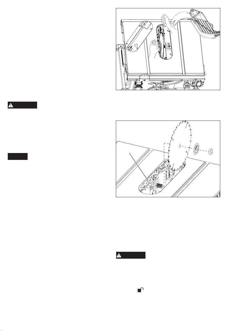
To change the saw blade:
1. Remove the battery pack.
2. Set the blade angle (bevel) to 0° and lock it in
place.
3. Raise the blade by turning the height adjusting
wheel clockwise.
4. Remove the riving knife.
5. Remove the throat plate.
6. Press in the spindle lock and rotate the spindle/
blade until the lock engages.
7. Use the blade wrench to loosen the blade bolt
counterclockwise. Carefully remove the blade
bolt and blade ange by hand. Remove the blade.
Wipe the blade bolt, anges and spindle to remove
dust and debris. Inspect the parts for damage.
Replace if needed.
the speed of this tool. Failure to
To work properly, the saw blade teeth
must point down toward the front of the
8. Match the arrow direction on the replacement saw
blade with the arrow direction on the riving knife.
The teeth should point toward the front of the table
saw. Slide the blade onto the spindle.
9. Install the outer blade ange. The at side of the
ange must rest against the blade.
Spindle lock
10. Hand-thread the blade bolt. Once the spindle
starts to spin, press in the spindle lock and rotate
the blade until the lock engages. Securely tighten
clockwise with the blade wrench.
11. Reinstall the appropriate throat plate, riving knife,
and anti-kickback pawls for the application.
12. Check blade guard and anti-kickback pawls move
freely before starting the saw. Ensure the blade
teeth match the direction of rotation indicated on
the riving knife.
Changing the Throat Plate
Always use the appropriate throat
blades may require dierent throat plates. Never
operate the saw without a throat plate in place.
1. Remove the battery pack.
2. Lower the blade by turning the height adjusting
wheel counterclockwise.
3. To remove a throat plate, turn the throat plate
latch to unlocked.
plate for the operation. Dierent
8

Throat plate
WARNING
WARNING
4. Use the hole to lift the throat plate out.
5. To install a throat plate, slide the back end into the
slot and drop the front into place. Turn the throat
plate latch to locked. The throat plate must be
ush with the saw table.
Throat plate latch
Lift hole
Changing the Riving Knife
Use the appropriate saw blade for
of blade (>1.8 mm) and blade body thickness
(<1.55 mm) with the marking on the riving knife
to reduce the risk of kickback. Failure to heed
this warning could result in personal injury.
Two riving knives are provided with the saw; the
riving knife with guard, and the riving knife without
guard. The riving knife with guard should be used for
through cutting operations for maximum protection
against kickback. When performing an operation
that requires "non-through cutting", use the riving
knife without guard. Do not use any riving knife when
making a dado cut.
Store the riving knife on the table saw frame when not in
use (see "Functional Description" for storage location).
To change the riving knife:
1. Remove the battery pack.
2. Raise the blade by turning the height adjusting
wheel clockwise.
3. Release the riving knife release lever.
4. To remove, pull the riving knife straight up.
5. To install, insert the riving knife into the slot
directly behind the blade until it is rmly seated.
NOTE: if the release lever is not fully open, the
riving knife may not fully seat.
6. Close the riving knife release lever fully.
7. Gently tug on the riving knife to ensure it is locked
into place.
8. When using the riving knife with guard, lift the
guard legs and ensure the move independently
and contact the table top. The guard legs can be
raised to line up the cut, but must be lowered to
contact the table top before starting the saw.
Release
lever
the riving knife. Match kerf width
Installing Anti-kickback Pawls
Always install the anti-kickback
guard when performing "through cutting" operations.
Replace dull or damaged anti-kickback pawls.
Dull or damaged pawls may not stop a kickback
increasing the risk of serious personal injury.
Anti-kickback pawls should only be installed for
through cuts.
1. Remove the battery pack.
2. Raise the blade by turning the height adjusting
wheel clockwise.
3. Install the riving knife with guard.
4. Press in the pawl release button and insert the slot
in the pawl joint into the riving knife notch. Press
down on the joint. NOTE: It may be easier to install
the pawls from the front of the saw.
5. Gently tug on the pawl joint to ensure it is locked
into place. Ensure the pawls move freely and are
not engaged in the throat plate slot.
1. Press button
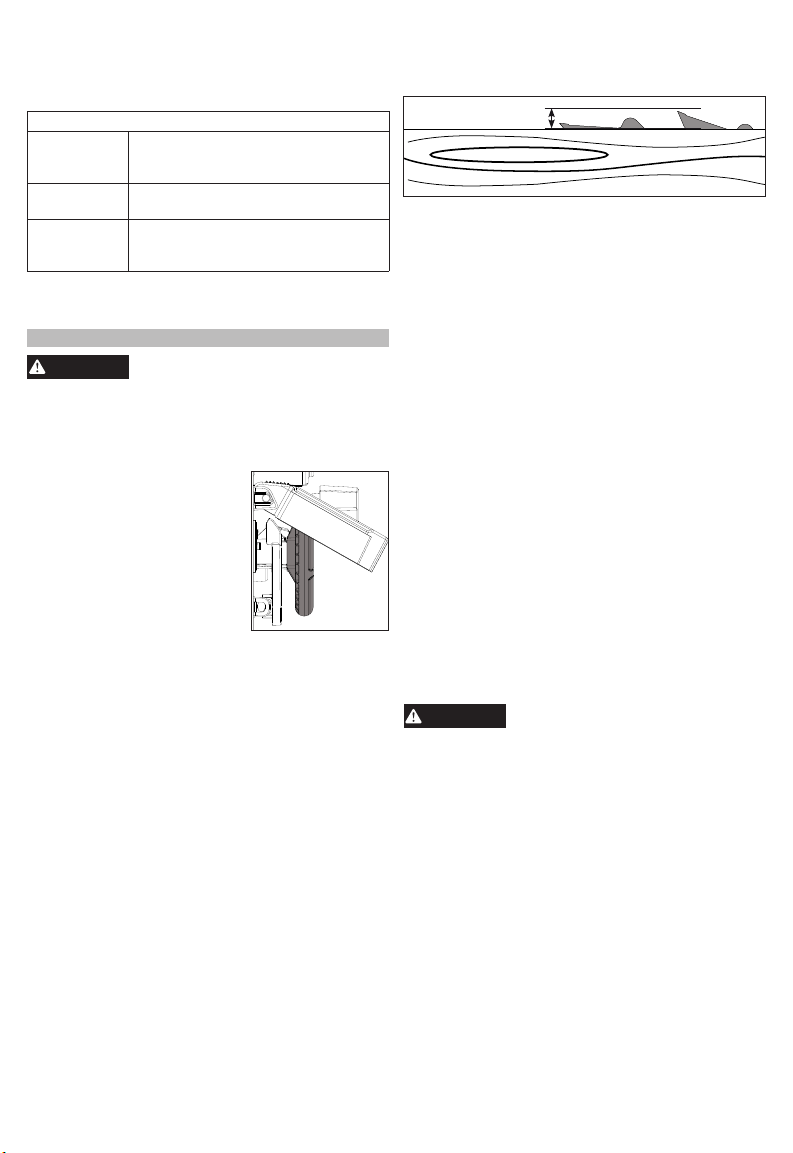
The blade depth should be set so that the outer
points of the blade are higher than the workpiece
by approximately 1/8" to 1/4" but the lowest points
(gullets) are below the top surface.
pawls onto the riving knife with
3. Press down
2. Insert
Changing Blade Depth
1/8" - 1/4"
1. Remove the battery pack.
2. Lower the blade by turning the height adjusting
wheel counterclockwise.
3. Raise the blade by turning the height adjusting
wheel clockwise.
Installing and Moving the Rip Fence
To install the rip fence on one of the fence posts:
1. Open the fence latches.
2. Fit the notches in the fence over the correspond-
ing fence posts.
3. Close the fence latches.
4. Check that the fence is square to the blade (see
"Blade to Fence Adjustment" in Maintenance).
To move the rip fence:
1. Pull the fence lock forward.
2. Use the fence adjusting knob to move the rip
fence left or right.
3. Push the fence lock back.
9
To use the extending rip
WARNING
fence as a table extension:
Use the extending rip fence
to hold the edge of the workpiece when the fence is
moved out past the end of
the table.
1. Pull the fence lock forward.
2. Use the fence adjusting
knob to move the extending rip fence out past the
edge of the table.
3. Flip the fence extension over. The tab on the
extending rip fence will t into the lower slot on
the fence.
4. Adjust the fence as needed and push the fence
lock back.
To use the extending rip
fence when cutting thin
(3/4" or less) workpieces
close to the blade:
NOTE: Only use the extending rip fence in this position
for workpieces 3/4" thick or
less. For thicker workpieces,
use the miter gauge.
Always use a push stick to
keep hands at least 3" away
from the blade.
1. Pull the fence lock forward.
2. Use the fence adjusting knob to move position
the rip fence.
3. Flip the fence extension over. Slide the extending
rip fence back, then push down. The tab on the
extending rip fence will t into the upper slot on
the fence.
4. Adjust the fence as needed and push the fence
lock back.
5. NOTE: If the fence is adjusted close to the blade,
ensure the guard and anti-kickback pawls move
freely. They may rest on top of the fence extension.
WARNING! Never stand directly in line with the
blade. Thin cut-o pieces can be thrown out and
toward the operator when the anti-kickback pawls
are not engaged with the wood.
To store the fence:
When making a cross cut or storing the tool, remove
and store the rip fence, as shown. The fence ts
around the fence lock. NOTE, the fence rail cannot
be adjusted when the fence is in the storage position.
Use an auxiliary fence for cutting thin pieces of wood,
such as veneer panels, that could get pinched under
the rip fence. To create an auxiliary fence, clamp a
1x4 piece of lumber (without beveled edges) to the
rip fence and ush to the table.
NOTE: A 90° cut has a 0° bevel and a 45° cut has
a 45° bevel.
1. Remove the battery pack.
2. Lift the bevel locking lever.
3. Grasp the height adjusting wheel and slide to the
4. Push down the bevel locking lever.
5. Check fence clearance before making a cut. Make
The miter gauge provides greater accuracy in angled
cuts. For very close tolerances, test cuts are recommended.
Miter Gauge
There are two miter gauge grooves, one on either
side of the blade. When making a 90° cross cut, you
can use either miter gauge groove. When making a
beveled cross cut (the blade tilted in relation to the
table) the miter gauge should be located in the groove
on the right so that the blade is tilted away from the
miter gauge and your hands.
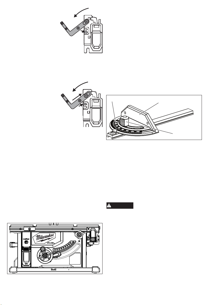
The miter gauge can be turned 60° to the right or left.
1. Loosen the lock knob.
2. With the miter gauge in the miter gauge groove,
3. Tighten the lock knob securely.
Using an Auxiliary Fence
Changing Blade Angle (Bevel)
desired bevel angle.
a sample cut before beginning work.
Using the Miter Gauge
Miter Gauge Body
Lock Knob
rotate the gauge until the desired angle is reached
on the scale.
Dust Collection
Collected sawdust from coated
workpieces can self-ignite and cause re. To
reduce the risk of re, empty frequently and
never store or leave a saw without totally emptying sawdust.
The dust chute at the back of the saw can be con-
nected to a vacuum hose (diameter 2.5"/62.6 mm). To
install, push and twist the hose onto the dust chute.
Leave dust chute open to direct dust down into a
garbage can.
Always store all saw parts, such as the fence, miter
gauge, riving knife, riving knife with guard, and blade
wrench, with the saw when transporting and storing.
Lower the blade, remove the battery pack and/or
lock-out the ON/OFF switch before transporting or
storing the saw.
(polyurethanes, linseed oil, etc.)
Transporting and Storing
10
To learn more about the ONE-KEY™ functionality
WARNING
WARNING
for this tool, go to milwaukeetool.com/One-Key. To
download the ONE-KEY™ app, visit the App Store or
Google Play from your smart device.
Solid Blue Wireless mode is active and ready
Blinking Blue Tool is actively communicating with
Blinking Red Tool is in security lockout and can
NOTE: High electronic discharge from the tool may
cause the ONE-KEY™ app to lose connection. Follow the prompts in the app to reconnect.
ONE-KEY™
ONE-KEY™ Indicator
to be congured via the ONE-KEY™
app.
the ONE-KEY™ app.
be unlocked by the owner via the
ONE-KEY™ app.
OPERATION
To reduce the risk of injury, always
to comply with ANSI Z87.1. Wear hearing protection.
When working in dusty situations, wear appropriate respiratory protection or use an OSHA
compliant dust extraction solution.
ALWAYS lock-out the trigger
when the tool is not in use.
Insert a standard padlock or
zip tie behind the switch to
prevent starting by untrained
users.
ALWAYS make sure your
workpiece is not in contact
with the blade before start the
tool. Workpiece contact may
cause the workpiece to be kicked back toward
the operator and result in serious personal injury.
Never stand directly in line with the blade or allow
hands to come closer than 3" to the blade. Do
not reach over or across the blade. Contact with
the blade can result in serious personal injury.
Ensure the saw is on a stable, level surface
before use.
Kickback can occur when the blade stalls or binds,
kicking the workpiece back toward you with great
force and speed. If your hands are near the saw
blade, they may be jerked loose from the workpiece
and may contact the blade. Obviously, kickback
can cause serious injury, and it is well worth using
precautions to avoid the risks.
Kickback can be caused by any action that pinches
the blade in the wood such as:
• Making a cut with incorrect blade depth
• Sawing into knots or nails in the workpiece
• Twisting the wood while making a cut
• Failing to support work
• Forcing a cut
• Cutting warped or wet lumber
• Using the wrong blade for the type of cut
• Not following correct operating procedures
• Misusing the saw
• Failing to use the anti-kickback pawls
• Cutting with a dull, gummed-up, or improperly set blade
wear proper eye protection marked
Causes of Kickback
• Always use the correct blade depth setting. The
top of the blade teeth should clear the workpiece
by 1/8" to 1/4".
Avoiding Kickback
1/8" - 1/4"
• Inspect the work for knots or nails before beginning
a cut. Knock out any loose knots with a hammer.
Never saw into a loose knot or nail.
• Always use the rip fence when rip cutting. Use the
miter gauge when cross cutting. This helps prevent
twisting the wood in the cut.
• Always use clean, sharp, and properly-set blades.
Never make cuts with dull blades.
• To avoid pinching the blade, support the work prop-
erly before beginning a cut.
• When making a cut, use steady, even pressure.
Never force cuts.
• Do not cut wet or warped lumber.
• Use extra caution when cutting some prenished
or composition wood products as the anti-kickback
pawls may not always be eective.
• Always guide your workpiece with both hands or
with push sticks and/or push blocks. Keep your
body in a balanced position to be ready to resist
kickback should it occur. Never stand directly in
line with the blade.
• Use of a featherboard will help hold the workpiece
securely against the saw table or fence.
• Clean the saw, blade guard, under the throat plate,
and any areas where saw dust or scrap workpieces
may gather.
• Use the right type of blade for the cut being made.
• Always use the riving knife for every operation where
it is allowed. The use of this device will greatly reduce the risk of kickback.
Turning Saw ON/OFF
Carefully check and lock all adjust-
revolution to assure proper clearance before
inserting the battery pack. Improper blade clear-
ance and loose adjustments can result in serious
personal injury.
When making a cross cut, make sure the blade
guard is installed and working properly to avoid
serious personal injury.
To reduce the risk of injury, always wear safety
goggles or glasses with side shields. Wear hearing protection and respiratory protection.
Remove zip tie before rst use.
1. Check all adjustments.
2. Insert the battery pack.
3. Line up the workpiece, but do not make contact
with the blade. NOTE: When using the riving knife
with guard, the guard legs can be raised to line up
the cut, but must be lowered to contact the table
top before starting the saw.
4. To turn the saw ON, lift the switch cover and then
lift the switch.
5. To turn the saw OFF, press the switch cover down.
11
ments, and rotate the blade one full
WARNING
Do not allow familiarity with tools
CAUTION
WARNING
2-1/2 in.
3/4 in.
1/4 in.
1/8 in.
1-1/16 in.
12 in.
70°
to make you careless. Remember
that a careless fraction of a second is sucient
to inict severe injury.
Do not use any attachments or accessories not
recommended by the manufacturer of this tool.
The use of attachments or accessories not recommended can result in serious personal injury.
Clearing a Jam/Cleaning the Dust Chute
To clear a jam:
1. Turn OFF the tool.
2. Remove the battery pack.
3. If unable to clear the
jam by removing the
throat plate, remove
the three bolts from the
dust chute and remove
the jam or debris from
the dust compartment.
Clean dust chute com-
pletely.
4. Reinstall all compo-
nents and check all adjustments before restarting work.
Dust
Chute
Bolts
APPLICATIONS
Use this tool for the purposes listed below:
• Straight line cutting operations such as cross cutting,
ripping, mitering, beveling, and compound cutting
• Dado with optional accessories
• Cabinet making and woodworking
NOTE: This table saw is designed to cut wood and
wood composition products only. Do not cut metal.
Do not cut plastics.
Cutting Aids
Push Sticks
Be sure the screws in a push block
are recessed to avoid damaging the
saw or workpiece.
(For rip cutting narrow workpiece)
If ripping a narrow workpiece places the hands too
close to the blade, it will be necessary to make and
use a jig.
To make a jig:
1. Attach a handle to a long, straight piece of wood
and secure from the underside using recessed
screws.
2. Cut an L-shaped stop in the side of the jig.
How to Make a Jig
Jig
Handle
Stop
To use a jig:
1. Position the workpiece at on the table with the
edge ush against the jig and against the stop.
2. Holding the jig handle and using a push block and/
or push stick, make the rip cut.
Featherboard
Place the featherboard against the
uncut portion of the workpiece to
avoid kickback that could cause serious personal injury.
A featherboard is a device used to help control the
workpiece by holding it securely against the table
or fence. Featherboards are especially useful when
ripping small workpieces and for completing non-
through cuts. The end is angled with a number of
short kerfs to give a friction hold on the workpiece
and locked in place on the table with a C-clamp. Test
to ensure it can resist kickback.
How to Make a Featherboard
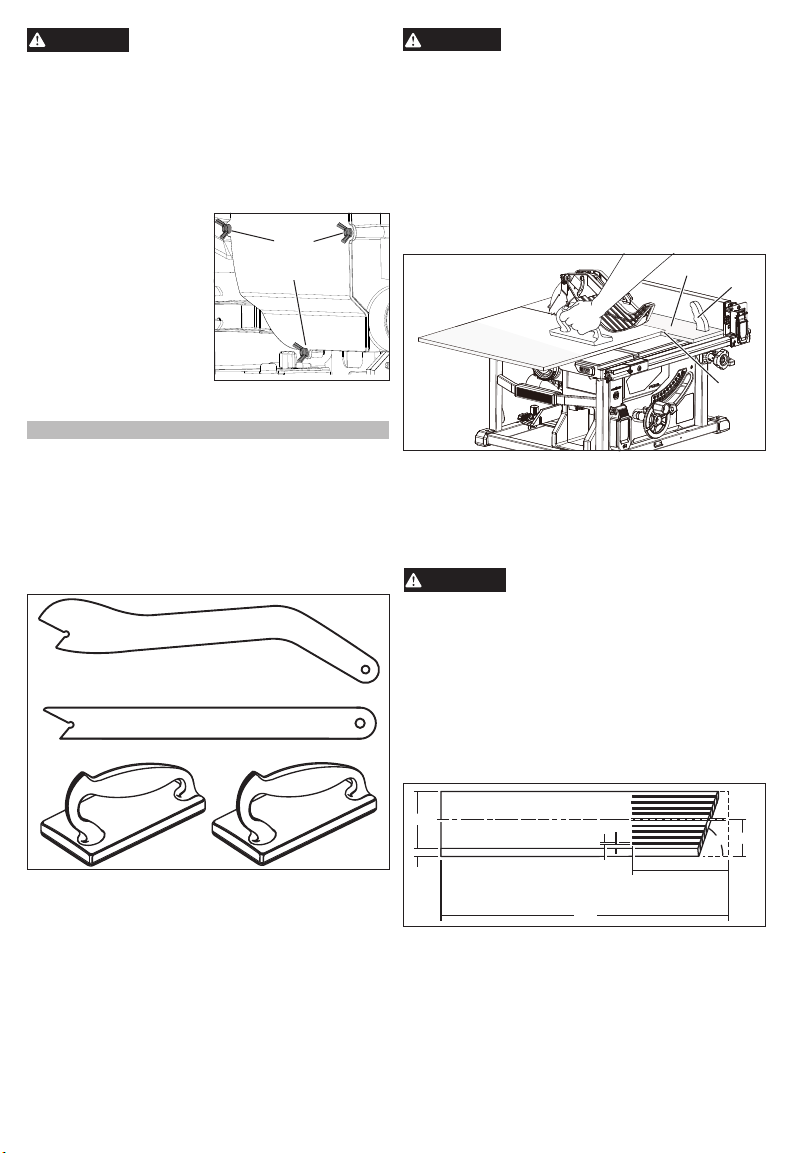
Push Blocks
Push sticks are devices that may be used for push-
ing a workpiece through the blade in any rip cut.
When making non-through cuts or ripping narrow
stock, always use a push stick, push block, and/or
featherboard so your hands do not come within 3"
of the saw blade. Use the push stick provided with
the table saw, or they can be made in various sizes
and shapes from scrap wood and used in a specic
project. The stick must be narrower than the workpiece, with a 90˚ notch in one end and shaping for a
grip on the other end.
A push block has a handle fastened by recessed
screws from the underside. Use push blocks for
narrow cuts and all non-through cuts.
Select a solid piece of lumber approximately 3/4"
thick, 2-1/2" wide and 12" long. Mark the center of the
width on one end of the stock. Miter the width to 70°.
Mark the board from the widest point at four inches.
Prepare the saw for ripping. Set the rip fence to allow
approximately a 1/4" “nger” to be cut in the stock.
Feed the stock only to the mark previously made at
4". Turn the saw OFF and allow the blade to com-
pletely stop rotating before removing the stock. Reset
the rip fence and cut spaced rips into the workpiece
to allow approximately 1/4" ngers and 1/8" spaces
between the ngers.
12
How to Mount a Featherboard
WARNING
WARNING
WARNING
Do not locate the featherboard to
tioned improperly, kickback can result from the
featherboard pinching the workpiece and binding
the blade in the saw kerf. Failure to heed this
warning can result in serious personal injury.
Completely lower the saw blade. Position the rip
fence to the desired adjustment for the cut to be
performed and lock. Place the workpiece against
the fence and over the saw blade area. Adjust the
featherboard to apply resistance to the workpiece
just forward of the blade. Attach C-clamps to further
secure the featherboard to the edge of the saw table.
Featherboard
Clamps
pawls are in place and working properly when
making these cuts to avoid possible injury.
Always use a push stick with small pieces of
wood, and also to nish the cut when ripping a
long narrow piece of wood, to prevent your hands
from getting close to the blade.
There are six basic cuts: the cross cut, the rip cut,
the miter cut, the bevel cross cut, the bevel rip cut,
and the compound (bevel) miter cut. All other cuts
are combinations of these basic six. Operating pro-
cedures for making each kind of cut are given later
in this section.
the rear of the workpiece. If posi-
Push stick
and block
Always make sure the riving knife
with blade guard and anti-kickback
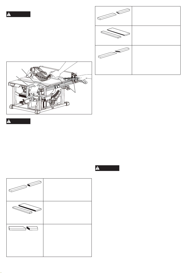
Types of Cuts
Cross Cut - Straight, 90° cuts
made across the grain of the
workpiece. The wood is fed
into the cut at a 90° angle to
the blade, and the blade is
vertical.
Rip Cut - Cuts made with the
grain of the wood. To avoid
kickback while making a rip
cut, make sure one side of the
wood rides rmly against the
rip fence.
Miter Cut - Cuts made with
the wood at any angle to the
blade other than 90°. The
blade is vertical. Miter cuts
tend to “creep” during cut-
ting. This can be controlled
by holding the workpiece
securely against the miter
gauge.
Bevel Cross Cut - Cuts made
with an angled blade. Bevel
cross cuts are across the
wood grain, and bevel rip cuts
are with the grain.
Bevel Rip Cut - Cuts made
with an angled blade. Bevel
cross cuts are across the
wood grain, and bevel rip cuts
are with the grain.
Compound (Bevel) Miter Cut
- Cuts made with an angled
blade on wood that is angled
to the blade. Be thoroughly familiar with making cross cuts,
rip cuts, bevel cuts, and miter
cuts before trying a compound
miter cut.
This table saw can perform a variety of cuts that are
not all mentioned in this manual. DO NOT attempt
to make any cuts not covered here unless you are
thoroughly familiar with the proper procedures and
necessary accessories. Your local library has many
books on table saw usage and specialized wood-
working procedures for your reference.
• Dado and rabbet cuts are non-through cuts which
can be either rip cuts or cross cuts. Carefully read
and understand all sections of this operator’s
manual before attempting these operations.
• The kerf (the cut made by the blade in the wood)
will be wider than the blade to avoid overheating or
binding. Make allowance for the kerf when measuring wood.
• Make sure the kerf is made on the waste side of
the measuring line.
• Cut the wood with the nish side up.
• Knock out any loose knots with a hammer before
making the cut.
• Always provide proper support for the wood as it
comes out of the saw.
Cutting Rules
To reduce the risk of injury from
kickback, check for proper alignment after tool has been stored, dropped or
bumped, or used extensively. A tool that is out
of alignment will cause binding and could result
in serious personal injury. See "Maintenance" for
proper adjustment procedure.
Carefully check and lock all adjustments, and
rotate the blade one full revolution to assure
proper clearance before inserting the battery
pack. Improper blade clearance and loose ad-
justments can result in serious personal injury.
Stand slightly to the side of the blade path to reduce the chance of injury should kickback occur.
Do not use blades rated less than the speed of
this tool. Failure to heed this warning could result
in personal injury.
13

Making a Cross Cut
WARNING
WARNING
WARNING
WARNING
Make sure the blade guard assem-
erly to avoid serious possible injury.
Using the rip fence as a cuto gauge when cross
cutting will result in kickback which can cause
serious personal injury.
1. Remove the battery pack.
2. Remove the rip fence.
3. Set the blade to the correct depth for the workpiece.
4. Set the miter gauge to 0° and tighten the lock knob.
5. Insert the battery pack.
6. Make sure the wood is clear of the blade before
turning on the saw.
NOTE: It is recommended that you place the piece
to be saved on the left side of the blade and that
you make a test cut on scrap wood rst.
7. Turn ON the saw. Allow the saw to come to full
speed.
8. Hold the workpiece rmly with both hands on the
miter gauge and feed the workpiece into the blade.
NOTE: The hand closest to the blade should be
placed on the miter gauge lock knob and the hand
farthest from the blade should be placed on the
workpiece.
9. Turn OFF the saw. Wait for the blade to come to
a complete stop before removing the workpiece.
bly is installed and working prop-
Making a Rip Cut
Make sure the blade guard assem-
erly to avoid serious possible injury.
Taper cuts must only be made with a special jig,
which is commercially available. Do not attempt
a free hand taper cut on this saw. Failure to follow these instructions could result in serious
personal injury.
1. Remove the battery pack.
2. Remove the miter gauge.
3. Install feather board in the appropriate position for
the cut being made.
4. Set the blade to the correct depth for the work-
piece.
5. Position the rip fence the desired distance from
the blade for the cut and lock in place.
6. When ripping a long workpiece, place a support
the same height as the table surface behind the
saw for the cut work.
7. Position the workpiece at on the table with the
edge ush against the rip fence.
8. Insert the battery pack.
9. Make sure the wood is clear of the blade before
turning on the saw.
10. Turn ON the saw. Allow the saw to come to full
speed.
11. Hold the workpiece rmly against the rip fence
and table. WARNING! Keep hands at least 3"
away from the blade at all times! If ripping a
narrow piece, use a push stick and/or push blocks
to move the piece through the cut and past the
blade. Once the blade has made contact with the
workpiece, use the hand closest to the rip fence to
guide it. Make sure the edge of the workpiece remains in solid contact with both the rip fence and
the surface of the table. If ripping a narrow piece,
use a push stick and/or push blocks to move the
piece through the cut and past the blade.
12. Turn OFF the saw. Wait for the blade to come to
a complete stop before removing the workpiece.
bly is installed and working prop-
Making a Miter Cut
Make sure the blade guard assem-
erly to avoid serious possible injury.
Using the rip fence as a cuto gauge when cross
cutting will result in kickback which can cause
serious personal injury.
The miter gauge must be on the right side of the
blade to avoid trapping the wood and causing
kickback. Placement of the miter gauge to the
left of the blade will result in kickback and the
risk of serious personal injury.
1. Remove the battery pack.
2. Remove the rip fence.
3. Set the blade to the correct depth for the work-
piece.
4. Set the miter gauge to the desired angle and
tighten the lock knob.
5. Insert the battery pack.
6. Make sure the wood is clear of the blade before
turning on the saw.
7. Turn ON the saw. Allow the saw to come to full
speed.
8. Hold the workpiece rmly with both hands on the
miter gauge and feed the workpiece into the blade.
NOTE: The hand closest to the blade should be
placed on the miter gauge lock knob and the hand
farthest from the blade should be placed on the
workpiece.
9. Turn OFF the saw. Wait for the blade to come to
a complete stop before removing the workpiece.
bly is installed and working prop-
Making a Bevel Cross Cut
Make sure the blade guard assem-
erly to avoid serious possible injury.
Using the rip fence as a cuto gauge when cross
cutting will result in kickback which can cause
serious personal injury.
The miter gauge must be on the right side of the
blade to avoid trapping the wood and causing
kickback. Placement of the miter gauge to the
left of the blade will result in kickback and the
risk of serious personal injury.
1. Remove the battery pack.
2. Remove the rip fence.
3. Adjust the bevel angle to the desired setting.
4. Set the blade to the correct depth for the work-
piece.
5. Set the miter gauge to 0° and tighten the lock knob.
6. Insert the battery pack.
7. Make sure the wood is clear of the blade before
turning on the saw.
8. Turn ON the saw. Allow the saw to come to full
speed.
9. Hold the workpiece rmly with both hands on
the miter gauge and feed the workpiece into
the blade. NOTE: The hand closest to the blade
should be placed on the miter gauge lock knob
and the hand farthest from the blade should be
placed on the workpiece.
10. Turn OFF the saw. Wait for the blade to come to
a complete stop before removing the workpiece.
14
bly is installed and working prop-

Making a Bevel Rip Cut
WARNING
WARNING
WARNING
WARNING
Make sure the blade guard assem-
erly to avoid serious possible injury.
The rip fence must be on the right side of the
blade to avoid trapping the wood and causing
kickback. Placement of the rip fence to the left
of the blade will result in kickback and the risk
of serious personal injury.
1. Remove the battery pack.
2. Remove the miter gauge.
3. Install feather board in the appropriate position for
the cut being made.
4. Adjust the bevel angle to the desired setting.
5. Set the blade to the correct depth for the workpiece.
6. Position the rip fence the desired distance from
the blade for the cut and lock in place.
7. When ripping a long workpiece, place a support
the same height as the table surface behind the
saw for the cut work.
8. Position the workpiece at on the table with the
edge ush against the rip fence.
9. Insert the battery pack.
10. Make sure the wood is clear of the blade before
turning on the saw.
11. Turn ON the saw. Allow the saw to come to full
speed.
12. Hold the workpiece rmly against the rip fence
and table. WARNING! Keep hands at least 3"
away from the blade at all times! If ripping a
narrow piece, use a push stick and/or push blocks
to move the piece through the cut and past the
blade. Once the blade has made contact with the
workpiece, use the hand closest to the rip fence to
guide it. Make sure the edge of the workpiece remains in solid contact with both the rip fence and
the surface of the table. If ripping a narrow piece,
use a push stick and/or push blocks to move the
piece through the cut and past the blade.
13. Turn OFF the saw. Wait for the blade to come to
a complete stop before removing the workpiece.
bly is installed and working prop-
Making a Compound (Bevel) Miter Cut
Make sure the blade guard assem-
erly to avoid serious possible injury.
The miter gauge must be on the right side of the
blade to avoid trapping the wood and causing
kickback. Placement of the miter gauge to the
left of the blade will result in kickback and the
risk of serious personal injury.
1. Remove the battery pack.
2. Remove the rip fence.
3. Adjust the bevel angle to the desired setting.
4. Set the blade to the correct depth for the workpiece.
5. Set the miter gauge to the desired angle and
tighten the lock knob.
6. Insert the battery pack.
7. Make sure the wood is clear of the blade before
turning on the saw.
8. Turn ON the saw. Allow the saw to come to full speed.
9. Hold the workpiece rmly with both hands on the
miter gauge and feed the workpiece into the blade.
NOTE: The hand closest to the blade should be
placed on the miter gauge lock knob and the hand
farthest from the blade should be placed on the
workpiece.
10. Turn OFF the saw. Wait for the blade to come to
a complete stop before removing the workpiece.
bly is installed and working prop-
Make sure the saw is properly secured to a work sur-
face to avoid tipping from the weight of a large panel.
erly to avoid serious possible injury.
Never make freehand cuts (cuts without the miter
gauge or rip fence). Unguided workpieces can
result in serious injury.
1. Remove the battery pack.
2. Set the blade to the correct depth for the work-
3. Depending on the shape of the panel, use the rip
4. Place a support the same height as the table sur-
5. Install a feather board in the appropriate position
6. Make sure the wood is clear of the blade before
7. Turn ON the saw. Allow the saw to come to full
8. Use proper hand positions for cross cut or rip cut,
9. Turn OFF the saw. Wait for the blade to come to
Non-through cuts can be made with the grain (rip-
ping) or across the grain (cross cut). The use of
a non-through cut is essential to cutting grooves,
rabbets, and dadoes. This is the only type cut that
is made without the riving knife with blade guard
installed. Use the riving knife without blade guard.
Make sure the blade guard assembly is reinstalled
upon completion of this type of cut. Read the appropriate section which describes the type of cut
in addition to this section on non-through or dado
cuts. For example, if your non-through cut is a rip
cut, read and understand the section on rip cuts
before proceeding.
piece during most of the cut. Be alert to the ex-
posed blade at the start and nish of every cut
to reduce the risk of personal injury.
Never feed wood with your hands when making
any non-through cut such as rabbets or dadoes.
To avoid personal injury, always use push blocks,
push sticks, and featherboards.
Do not make complex non-through cuts, such as
plunge cuts, resawing, moulding head cutting,
or plowing.
1. Remove the battery pack.
2. Remove the riving knife with blade guard and
3. Install the riving knife.
4. Adjust the bevel angle to 0°.
5. Set the blade to the correct depth for the workpiece.
6. Depending on the shape and size of the work-
7. Install a feather board in the appropriate position
8. Insert the battery pack.
9. Make sure the wood is clear of the blade before
15
Making a Large Panel Cut
Make sure the blade guard assembly is installed and working prop-
piece.
fence or miter gauge. If the panel is too large to
use either the rip fence or the miter gauge, it is
too large for this saw.
face behind the saw for the cut work. Add supports
to the sides as needed.
for the cut being made.
turning on the saw.
speed.
as necessary.
a complete stop before removing the workpiece.
Making a Non-Through Cut
When making a non-through cut,
the blade is covered by the work-
anti-kickback pawls.
piece, use the rip fence or miter gauge.
for the cut being made.
turning on the saw.

10. Turn ON the saw. Allow the saw to come to full
WARNING
WARNING
speed.
11. Use a push stick and/or push blocks to move the
piece into the cut.
12. Turn OFF the saw. Wait for the blade to come to
a complete stop before removing the workpiece.
13. Once all non-through cuts are complete, remove
the battery pack and reinstall the riving knife with
guard and anti-kickback pawls.
Making a Dado Cut
Blades are sharp. Wear work gloves
Always remove riving knife before
making a dado cut.
An optional dado throat plate is required for this procedure (For a complete listing of accessories, go online to
www.milwaukeetool.com or contact a
distributor). All blades and dado sets must
not be rated less than the speed of this
tool. This saw is designed for use with a 6" stack
dado (up to width of 3/4"). Do not use an adjustable
dado or molding cutters on this saw.
piece during most of the cut. Be alert to the ex-
posed blade at the start and nish of every cut
to reduce the risk of personal injury.
To avoid personal injury, always use push blocks,
push sticks, and featherboards.
1. Remove the battery pack.
2. Remove the riving knife with blade guard and
anti-kickback pawls.
3. Remove the standard blade and install the dado
blade, according to manufacturer instructions,
using the blade and chippers appropriate for the
desired width of cut. NOTE: Always store the throat
plate, blade, ange, and bolt in a secure location.
4. Install the dado throat plate and rotate the blade
by hand to make sure it turns freely then lower
the blade.
5. Depending on the shape and size of the work-
piece, use the rip fence or miter gauge.
6. Install a feather board in the appropriate position
for the cut being made.
7. Insert the battery pack.
8. Make sure the wood is clear of the blade before
turning on the saw.
9. Turn ON the saw. Allow the saw to come to full
speed.
10. Use a push stick and/or push blocks to move the
piece into the cut.
11. Turn OFF the saw. Wait for the blade to come to
a complete stop before removing the workpiece.
12. Once all non-through cuts are complete, remove
the battery pack and reinstall the standard blade,
throat plate, riving knife with guard and anti-
kickback pawls.
when handling blades.
When making a non-through cut,
the blade is covered by the work-
Troubleshooting
Problem Cause Solution
Excess
vibration.
Rip fence
does not
move
smoothly.
Cutting
binds or
burns work.
Wood
edges away
from rip
fence when
ripping.
Saw does
not make
accurate
90˚ or 45˚
cuts.
Height
adjusting
hand-wheel
is hard to
turn.
S
aw does
not start.
Blade
makes poor
cuts.
Motor
labors in rip
cut.
B
lade is out of
balance.
Blade is damaged.
Saw is not mounted
securely.
Work surface is
uneven.
Blade is warped.
Rip fence not
mounted correctly.
Rails are dirty or
sticky.
Blade is dull.
Blade is heeling.
Work is fed too fast.
Rip fence is
misaligned.
Wood is warped.
Riving knife is out of
alignment.
Blade not properly
sharpened or set.
Bevel adjustment is
out of alignment.
Gears or screw post
inside cabinet are
clogged with saw
dust.
Battery pack is at end
of charge.
Battery pack contacts
are dirty.
Blade is dull or dirty.
Blade is wrong type
for cut being made.
Blade is mounted
backwards.
Blade not proper for
rip cut.
Work is fed to fast
into blade.
Replace blade.
Replace blade.
Tighten all
hardware.
Reposition on at
surface. Adjust legs
of optional stand.
Check saw blade
installation.
Replace blade if
necessary.
Remount the rip
fence.
Clean rails.
Replace or sharpen
blade.
See
Blade to Miter
Slot Adjustment
(Heeling)
.
Slow the feed rate.
Align the rip fence.
Replace the wood.
Always cut with
convex side to
table surface.
See Riving Knife
to Saw Blade
Adjustment.
Resharpen or set
blade.
See Bevel
Adjustments at 0°
and 45°
Clean the gears or
screw post.
Charge battery
pack.
Clean battery pack
contacts.
Clean, sharpen, or
replace blade.
Replace with
correct type.
Remount blade.
Change blade; rip
blade typically has
fewer teeth.
Slow feed rate.
16

Saw
WARNING
WARNING
WARNING
WARNING
shuts o
unexpectedly
Battery overtemperature
Allow battery to
cool for 10 minutes
before use.
MAINTENANCE
To reduce the risk of injury, always
battery pack from the charger or tool before
performing any maintenance. Never disassemble
the tool, battery pack or charger. Contact a
MILWAUKEE service facility for ALL repairs.
Keep your tool, battery pack and charger in good
repair by adopting a regular maintenance program.
Inspect your tool for issues such as undue noise,
misalignment or binding of moving parts, breakage of
parts, or any other condition that may aect the tool
operation. Return the tool, battery pack, and charger
to a MILWAUKEE service facility for repair. After six
months to one year, depending on use, return the
tool, battery pack and charger to a MILWAUKEE
service facility for inspection.
If the tool does not start or operate at full power with
a fully charged battery pack, clean the contacts on
the battery pack. If the tool still does not work properly, return the tool, charger and battery pack, to a
MILWAUKEE service facility for repairs.
ment after tool has been stored, dropped or
bumped, or used extensively. A tool that is out
of alignment will cause binding and could result
in serious personal injury.
unplug the charger and remove the
Maintaining Tool
To reduce the risk of injury from
kickback, check for proper align-
When making adjustments, follow this
order:
1. Throat Plate Adjustment
2. Blade Angle (Bevel) Adjustments at 0° and 45°
3. Blade to Miter Slot Adjustment
4. Blade to Fence Adjustment
5. Riving Knife to Saw Blade Adjustment
To reduce the risk of injury, always
performing any maintenance or adjustments.
blades may require dierent throat plates. Never
operate the saw without a throat plate in place.
A properly adjusted throat plate is important for a
smooth cut. The front of the throat plate must be
slightly lower or ush with the table top. The back of
the throat plate must be slightly higher than the table
top (0 to 0.027"). Check throat plate each time the
throat plate is changed, and periodically before use.
If the throat plate is not properly adjusted:
1. Remove the battery pack.
2. Remove the riving knife with guard.
3. Lower the blade by turning the height adjusting
wheel counterclockwise.
4. Use the throat plate set screws (2.5 mm) to adjust
the front and back heights.
5. Re-measure and repeat until the throat plate is
properly adjusted.
remove the battery pack before
1. Adjusting the Throat Plate
Always use the appropriate throat
plate for the operation. Dierent
Throat Plate Set Screws
2. Blade Angle (Bevel) Adjustment
The angle settings of the saw have been set at the
factory and, unless damaged in shipping, should not
require setting during assembly. After extensive use,
they should be rechecked and adjusted if necessary.
1. Remove the battery pack.
2. Set the blade angle to 0° and lock into place.
3. Raise the blade by turning the height adjusting
wheel clockwise.
4. Remove the riving knife.
To check for 0°:
5. Place a combination square
beside the blade on the
right. The edge of the
square and the saw blade
should be parallel. NOTE:
Make sure that the square
contacts the at part of the
saw blade, not the blade
teeth.
6. If the blade and square are
not parallel:
• Unlock the bevel locking
lever.
• Loosen the 0° adjustment screw.
0° Adjustment Screw
• Adjust the blade to the 0° position
• Lock the bevel locking lever.
• Rotate the cam until it contacts the bevel
• Tighten the adjustment screw. Check again for
square and continue to adjust if needed.
7. Once square, loosen the pointer screw and adjust
the pointer to 0°.
0° Cam
at 0° and 45°
Pointer
Screw
17

To check for 45°:
WARNING
8. Set the blade angle to 45° and lock into place.
9. Place a combination
square beside the blade
on the right using the 45°
side. The edge of the 45°
side of the square and the
saw blade should be parallel. NOTE: Make sure
that the square contacts
the flat part of the saw
blade, not the blade teeth.
10. If the blade and square
are not parallel:
• Unlock the bevel locking lever.
• Loosen the 45° adjustment screw.
45° Adjustment Screw
45° Cam
• Adjust the blade to the 45° position
• Lock the bevel locking lever.
• Rotate the cam until it contacts the bevel
• Tighten the adjustment screw. Check again for
square and continue to adjust if needed.
11. Make a test cut at both 0° and 45° to check.
3. Blade to Miter Slot Adjustment (Heeling)
1. Remove the battery pack.
2. Set the blade angle (bevel) to 0° and lock into
place.
3. Raise the blade by turning the height adjusting
wheel clockwise.
4. Measure from front of blade to miter slot and back
of blade to miter slot. They must be equal.
5. If the blade is not square to the miter slot,
loosen the front or back blade adjustment screws
(4 mm hex) located from the bottom of the saw.
Blade Adjustment Screws
(from bottom of saw)
6. Slide the blade compartment left or right and
tighten the blade adjustment screws.
7. Recheck the front and back blade to slot measurements again.
8. Repeat until the blade is square to the miter slot.
4. Blade to Fence Adjustment
The rip fence must be parallel to the saw blade and
the miter gauge grooves.
risk of injury, always maintain proper rip fence
alignment.
1. Remove the battery pack.
2. Set the blade angle (bevel) to 0° and lock into
place.
3. Raise the blade by turning the height adjusting
wheel clockwise.
4. Remove the riving knife with guard.
5. Lock the fence onto Post A.
Post C Tape Screw Post A Post B
A misaligned rip fence can cause
kickbacks and jams. To reduce the
6. Slide the fence over to touch blade and lock the
fence lock lever.
18

7. Blade should contact fence evenly, front to back.
8. If not, use a 4 mm hex wrench to loosen the appropriate fence post (front and/or back). Slide the
post left or right as needed, and tighten securely.
9. Repeat until the fence touches the blade evenly.
10. To adjust the rip scale indicator to zero, use a 4
mm hex wrench to loosen the bolt and slide the
indicator to line up with zero on the silver tape.
Retighten the bolt.
11. Lock the fence onto Post B.
12. Measure from front of blade to fence and back
of blade to fence. Both must be 4".
13. If not, use a 4 mm hex wrench to loosen the ap-
propriate fence post (front and/or back). Slide the
post left or right as needed, and tighten securely.
14. Repeat until the fence measures 4" from front of
blade to fence and back of blade to fence. Fence
should rest completely on fence rail with hanging
o the edge of the fence rail.
15. Lock the fence onto Post C.
16. Slide the fence over to touch blade and lock the
fence lock lever.
17. Blade should contact fence evenly, front to back.
18. If not, use a 4 mm hex wrench to loosen the ap-
propriate fence post (front and/or back). Slide the
post left or right as needed, and tighten securely.
19. Repeat until the fence touches the blade evenly.
Fence should rest completely on fence rail with
hanging o the edge of the fence rail.
20. Make two or three test cuts on scrap wood from
each fence location. If the cuts are not true,
repeat the process.
5. Riving Knife to Saw Blade Adjustment
To check the alignment of the riving knife:
1. Remove the battery pack.
2. Raise the blade by turning the height adjusting
wheel clockwise.
3. Remove the anti-kickback pawls from the riving
knife with blade guard.
4. Remove the riving knife and place at on the table.
Riving knife must lay at and not tip when an edge
is touched. If the riving knife is not at, replace the
riving knife before using the saw.
5. Place a speed square or straight edge against riv-
ing knife over the saw blade. The saw blade and
riving knife are aligned when the speed square
contacts the riving knife on BOTH sides, without
making contact with the blade. There should be a
very thin gap between the square and the blade.
The square should not contact the blade teeth.
If the riving knife is out of alignment with the saw
blade, adjustment is needed. The riving knife must
be in alignment front to back (horizontally) and top
to bottom (vertically).
To adjust:
1. Remove the battery pack.
2. Remove the throat plate.
3. Install the blade.
4. Install the riving knife or riving knife with guard.
NOTE: Recheck and adjust for each change in
riving knife or blade.
5. Loosen the riving knife adjustment screws
(4 mm hex).
Riving Knife
Riving Knife
Adjustment
Screws
Set Screws
6. Tighten or loosen the 3 riving knife set screws
(2.5 mm hex) as needed.
7. Tighten the riving knife adjustment screws.
19

8. Recheck both sides of the blade/riving knife.
WARNING
WARNING
WARNING
9. Repeat until riving knife is properly adjusted to
the blade.
10. Once adjusted, remove the riving knife, reinstall
the throat plate, then reinstall the riving knife
and anti-kickback pawls (if appropriate for the
operation).
ONE-KEY™
Chemical Burn Hazard.
lithium button/coin cell battery. A new
or used battery can cause severe internal burns and lead to death in as
little as 2 hours if swallowed or enters the body.
Always secure the battery cover. If it does not
close securely, stop using the device, remove the
batteries, and keep it away from children. If you
think batteries may have been swallowed or en-
This device contains a
tered the body, seek immediate medical attention.
An internal coin cell battery is used to facilitate full
ONE-KEY™ functionality.
To replace the coin cell battery:
1. Remove the battery pack.
2. Remove the screw(s) and open the coin cell bat-
3. Remove the old coin cell battery, keep it away from
4. Insert the new coin cell battery (3V CR2032), with
5. Close the battery door and tighten the screw(s)
Internal Coin Cell Battery
tery door.
children, and dispose of it properly.
the positive side facing up.
securely.
To reduce the risk of personal injury and damage, never immerse
your tool, battery pack or charger in liquid or
allow a liquid to ow inside them.
Clean dust and debris from any vents. Keep tool
clean, dry and free of oil or grease. Use only mild
soap and a damp cloth to clean, since certain cleaning agents and solvents are harmful to plastics and
other insulated parts. Some of these include gasoline,
turpentine, lacquer thinner, paint thinner, chlorinated
cleaning solvents, ammonia and household deter-
gents containing ammonia. Never use ammable or
combustible solvents around tools.
For repairs, return the tool, battery pack and charger
to the nearest authorized service center.
Cleaning
Repairs
ACCESSORIES
Use only recommended accesso-
For a complete listing of accessories, go online to
www.milwaukeetool.com or contact a distributor.
ries. Others may be hazardous.
WIRELESS COMMUNICATION
For products provided with wireless communication
features, including ONE-KEY™:
Pursuant to part 15.21 of the FCC Rules, do not
modify this product. Modication could void your
authority to operate the product. This device complies
with part 15 of the FCC Rules and ISED-Canada's
license exempt RSS standards. Operation is subject
to the following two conditions: 1) This device may
not cause harmful interference, and 2) This device
must accept any interference received, including
interference that may cause undesired operation.
SERVICE - UNITED STATES
1-800-SAWDUST (1.800.729.3878)
Monday-Friday, 7:00 AM - 6:30 PM CST
or visit www.milwaukeetool.com
Contact Corporate After Sales Service Technical
Support with technical, service/repair, or warranty
questions.
Email: metproductsupport@milwaukeetool.com
Become a Heavy Duty Club Member at
www.milwaukeetool.com to receive important
notications regarding your tool purchases.
SERVICE - CANADA
Milwaukee Tool (Canada) Ltd
Monday-Friday, 7:00 AM - 4:30 PM CST
This MILWAUKEE power tool* is warranted to the original purchaser
from an authorized MILWAUKEE distributor only to be free from
defects in material and workmanship. Subject to certain exceptions,
MILWAUKEE will repair or replace any part on this power tool which,
after examination, is determined by MILWAUKEE to be defective
in material or workmanship for a period of ve (5) years after the
date of purchase unless otherwise noted. Return of the power tool
to a MILWAUKEE factory Service Center location or MILWAUKEE
Authorized Service Station, freight prepaid and insured, is required.
A copy of the proof of purchase should be included with the return
product. This warranty does not apply to damage that MILWAUKEE
determines to be from repairs made or attempted by anyone other
than MILWAUKEE authorized personnel, misuse, alterations, abuse,
normal wear and tear, lack of maintenance, or accidents.
Normal Wear: Many power tools need periodic parts replacement and
service to achieve best performance. This warranty does not cover
repair when normal use has exhausted the life of a part including,
but not limited to, chucks, brushes, cords, saw shoes, blade clamps,
o-rings, seals, bumpers, driver blades, pistons, strikers, lifters, and
bumper cover washers.
*This warranty does not cover battery packs or all power tools. Refer
to the separate and distinct warranties available for those products.
The warranty period for the LED in the LED Work Light (49-24-0171)
and the LED Upgrade Bulb (49-81-0090) is the lifetime of the product
subject to the limitations above. If during normal use the LED or LED
Upgrade Bulb fails, the part will be replaced free of charge.
Warranty Registration is not necessary to obtain the applicable war-
ranty on a MILWAUKEE power tool product. The manufacturing date
of the product will be used to determine the warranty period if no proof
of purchase is provided at the time warranty service is requested.
ACCEPTANCE OF THE EXCLUSIVE REPAIR AND REPLACEMENT
REMEDIES DESCRIBED HEREIN IS A CONDITION OF THE CON-
TRACT FOR THE PURCHASE OF EVERY MILWAUKEE PRODUCT.
IF YOU DO NOT AGREE TO THIS CONDITION, YOU SHOULD NOT
PURCHASE THE PRODUCT. IN NO EVENT SHALL MILWAUKEE BE
LIABLE FOR ANY INCIDENTAL, SPECIAL, CONSEQUENTIAL, OR
PUNITIVE DAMAGES, OR FOR ANY COSTS, ATTORNEY FEES,
EXPENSES, LOSSES OR DELAYS ALLEGED TO BE AS A CON-
SEQUENCE OF ANY DAMAGE TO, FAILURE OF, OR DEFECT IN
ANY PRODUCT INCLUDING, BUT NOT LIMITED TO, ANY CLAIMS
FOR LOSS OF PROFITS. SOME STATES DO NOT ALLOW THE EXCLUSION OR LIMITATION OF INCIDENTAL OR CONSEQUENTIAL
DAMAGES, SO THE ABOVE LIMITATION OR EXCLUSION MAY NOT
APPLY TO YOU. THIS WARRANTY IS EXCLUSIVE AND IN LIEU
OF ALL OTHER EXPRESS WARRANTIES, WRITTEN OR ORAL.
TO THE EXTENT PERMITTED BY LAW, MILWAUKEE DISCLAIMS
ANY IMPLIED WARRANTIES, INCLUDING WITHOUT LIMITATION
ANY IMPLIED WARRANTY OF MERCHANTABILITY OR FITNESS
FOR A PARTICULAR USE OR PURPOSE; TO THE EXTENT SUCH
DISCLAIMER IS NOT PERMITTED BY LAW, SUCH IMPLIED WARRANTIES ARE LIMITED TO THE DURATION OF THE APPLICABLE
EXPRESS WARRANTY AS DESCRIBED ABOVE. SOME STATES
DO NOT ALLOW LIMITATIONS ON HOW LONG AN IMPLIED WARRANTY LASTS, SO THE ABOVE LIMITATION MAY NOT APPLY TO
YOU, THIS WARRANTY GIVES YOU SPECIFIC LEGAL RIGHTS,
AND YOU MAY ALSO HAVE OTHER RIGHTS WHICH VARY FROM
STATE TO STATE.
This warranty applies to product sold in the U.S.A. and Canada only.
Please consult the ‘Service Center Search’ in the Parts & Service sec-
tion of MILWAUKEE’s website www.milwaukeetool.com or call 1.800.
SAWDUST (1.800.729.3878) to locate your nearest service facility
for warranty and non-warranty service on a MILWAUKEE power tool.
20
1.877.948.2360
or visit www.milwaukeetool.ca
LIMITED WARRANTY
USA & CANADA
 Loading...