

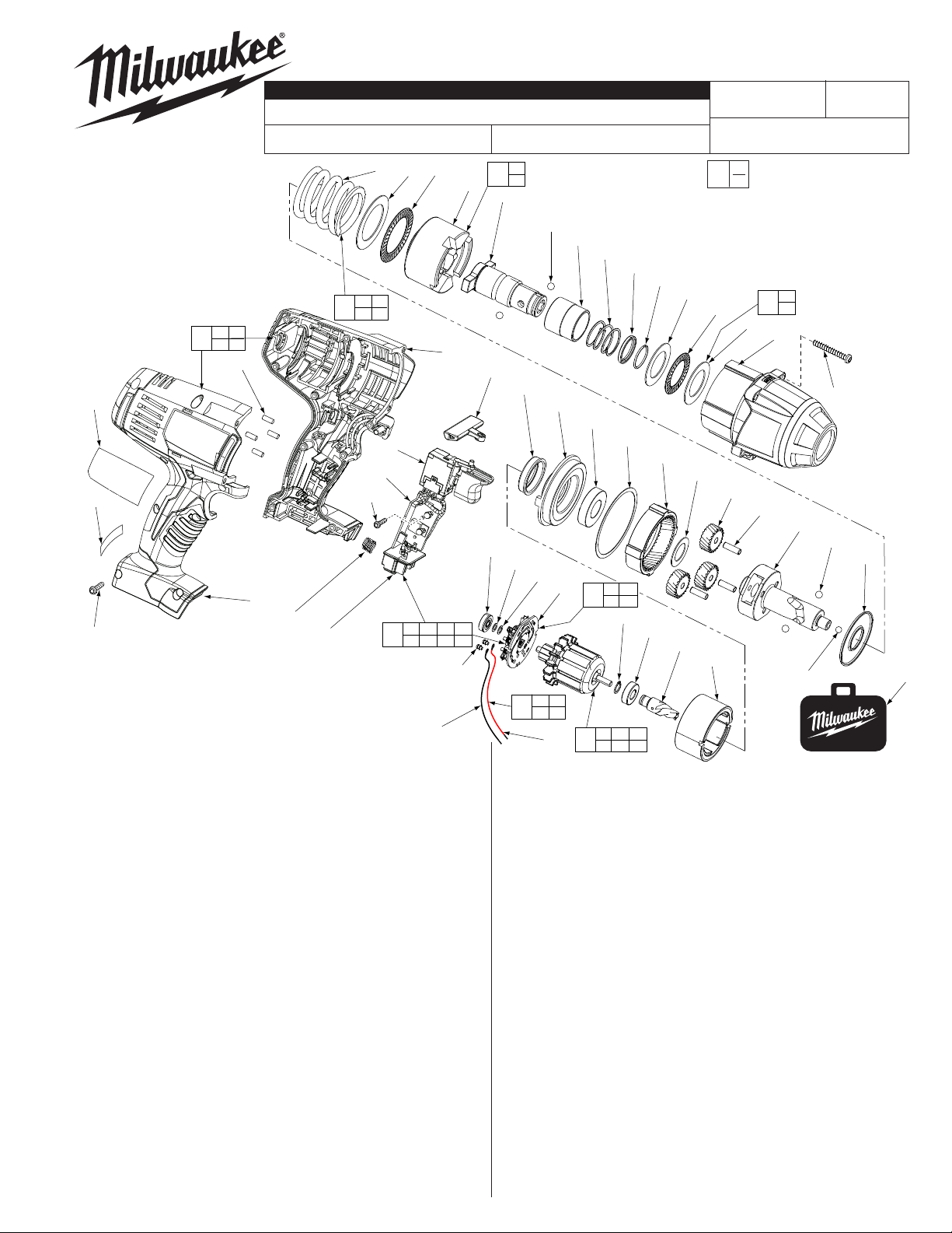
SERVICE PARTS LIST
SPECIFY CATALOG NO. AND SERIAL NO. WHEN ORDERING PARTS
M18™ 7/16" HEX IMPACT WRENCH
CATALOG NO.
= Part number change from
«
previous service parts list.
71
39 40
48
43
43
62
63
40
42
FIG. PART NO. DESCRIPTION OF PART NO.REQ.
4 05-88-5988 M5 X 35mm Pan Hd. Slt. T-20 Screw (4)
5 14-30-0965
6 --------------- Washer (2)
7 --------------- Thrust Bearing (1)
10 45-88-1006 Washer (1)
11 42-06-0701 7/16" Hex Anvil (1)
«
12 --------------- Hammer (1)
13 02-80-0200 Thrust Bearing (1)
15 --------------- Compression Spring (1)
16 45-88-1650 Washer (1)
17 02-02-7010 7/32" Ball (1)
18 02-02-0250 1/4" Ball (2)
19 --------------- Camshaft (1)
«
20 32-65-0260 Ring Gear (1)
21 32-62-0500 Planet Gear (3)
22 44-60-1960 Pin (3)
23 45-88-1655 Washer (1)
24 02-04-0375 Ball Bearing (1)
25 34-40-0290 Seal Ring (1)
26 44-66-0895 Motor Mount Plate (1)
27 --------------- Ball Bearing - Front (1)
28 --------------- Pinion (1)
29 18-01-3025 Service Field Assembly (1)
31 --------------- Brush Card (1)
32 --------------- Washer (1)
33 --------------- Ball Bearing - Rear (1)
35 45-24-0570 Forward / Reverse Shuttle (1)
36 --------------- Switch (1)
37 --------------- Connector Block (1)
38 40-50-1090 Compression Spring (1)
39 --------------- Handle - Left (1)
40 --------------- Handle - Right (1)
42 06-82-0995 M4 x 16mm Pan Hd. T-20 Screw (9)
43 45-30-0255 Rubber Slug (4)
44 16-01-3030 Armature Assembly (1)
47 --------------- Retaining Ring (1)
48 31-44-0696 Handle Set (1)
49 45-22-0380 Rubber Cap (1)
Front Housing Assy. w/ Bushing and O-Rings
38
37
10 13
15
61
78
2665-20
15
10
36
31 36 37 61
50
73 74 75
13
39
73(2x)
75
(1)
12
69
35
33
BULLETIN NO.
54-26-2692
REVISED BULLETIN
54-26-2691
STARTING
SERIAL NO.
12
19
11
65
49
26
32
64
31
73 74
76
75
74
FIG. PART NO. DESCRIPTION OF PART NO.REQ.
50 22-56-1451 Switch/Connector Block Assembly (1)
51 42-76-0185 Collar (1)
52 40-50-0365 Collar Spring (1)
53 44-90-0020 Support Ring (1)
54 34-60-0050 Retaining Ring (1)
61 --------------- PCBA (1)
62 12-20-2670 Service Nameplate Kit (1)
63 10-20-2695 Warning Label (1)
64 --------------- Washer (1)
65 02-02-0250 1/4" Ball (2)
66 42-55-2665 Carrying Case, Optional (1)
69 14-46-2071 Camshaft/Hammer Service Kit (1)
«
70 45-88-1877 Washer/Bearing Kit (1)
71 14-46-0755 Spring/Washer/Bearing Kit (1)
73 05-88-0920 M3 x 0.5 x 5mm PH T10 Washer Scr. (2)
«
74 --------------- Leadwire Assembly - Red (1)
75 --------------- Leadwire Assembly - Black (1)
76 14-46-2395 Leadwire/Screw/Washer Kit (1)
77 14-46-2024 Brush Card Assembly (1)
78 06-82-2395 M2.6 x 10 Pan Hd. T-8 Screw (1)
FIG. LUBRICATION
(Type 'Z' Grease, No. 49-08-7655):
20,21 Lightly coat the I.D. of the Ring Gear (20) and the center of
the three Planet Gears (21) with grease.
19 Place a dab of grease in ball grooves of the Cam Shaft (19).
11 Lightly coat the front washer surface of Anvil (11) with grease,
place a dab in the Ball hole on the backside of Anvil.
3 Coat outside grooves of Bushing (3) with grease.
51
24
77
44
B82C
52
53
54
6
25
20
23
31 73
74 75
47
27
28
27 28 32
33 47 64
WIRING INSTRUCTION
See Page 3
EXAMPLE:
00
Component Parts (Small #)
0
Are Included When Ordering
The Assembly (Large #).
70
7
6
21
22
29
6
7
5
19
17
MILWAUKEE ELECTRIC TOOL CORPORATION
13135 W. LISBON RD., BROOKFIELD, WI 53005
DATE
Jan. 2023
4
18
16
66
Drwg. 2
Black
Red
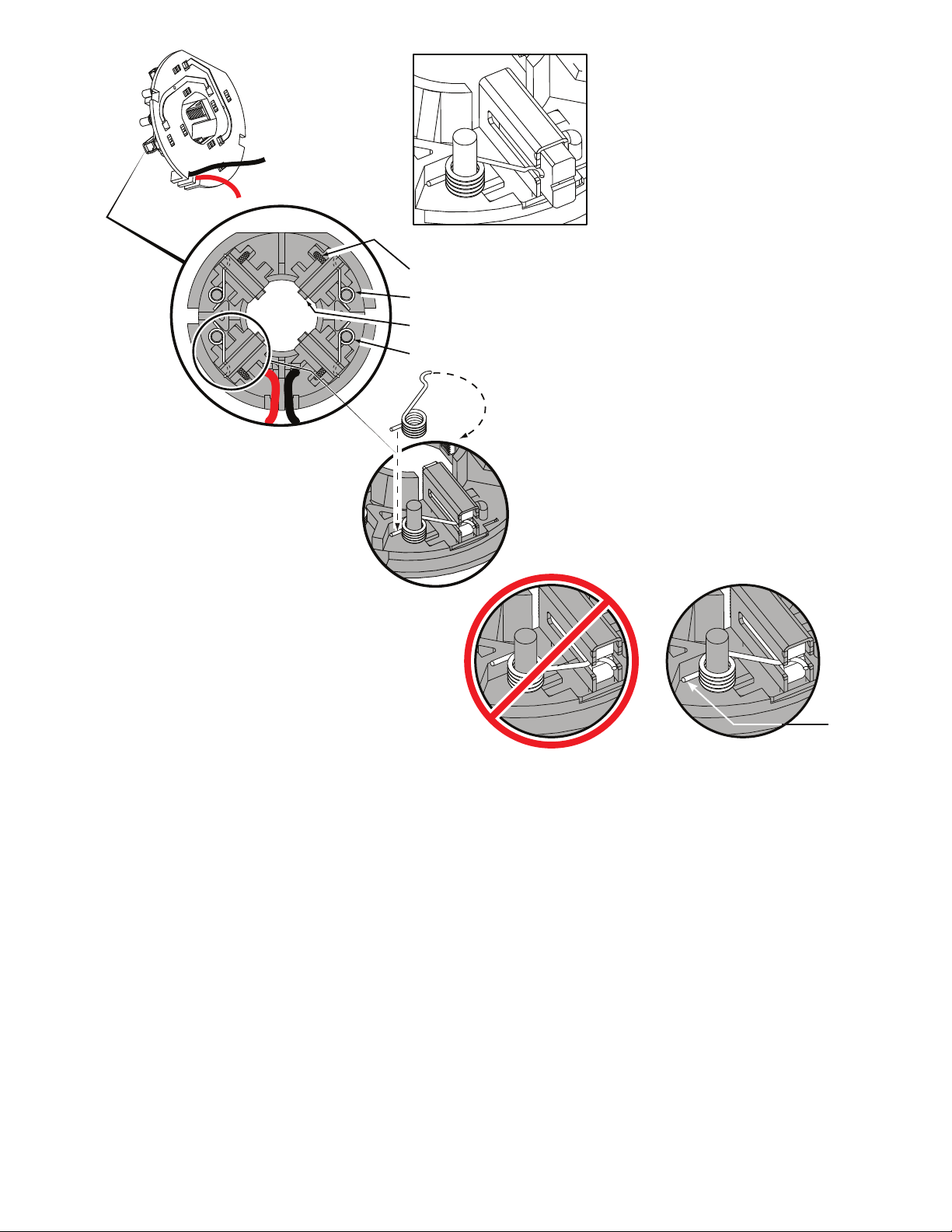
Brush Card Assy.
NOTE:
As an aid to prevent damage to the armature
commutator or the brushes when removing and
installing the armature assembly, it is recommended to
pull the carbon brushes partially back into the brush
tube. The carbon brushes will be held in place with the
brush spring moving from the rear of the brush to the
side of the brush.
In the unlikely event that the spring pops off follow the
instructions below.
Brush Shunt (4 places)
Right Brush Spring (2x)
Carbon Brush (4x)
Be sure carbon
brush is in brush tube
with brush shunt moving
freely in side groove of tube.
Place brush spring over post with short leg
positioned downward as shown. Be sure spring
is completely down with short leg trapped against
'Y' shaped wall on brush card.
While holding spring in place, bring the long leg of
spring over the brush tube and through rear opening
of tube. Position rounded hook of spring in groove on
back of carbon brush. Be sure to check for free movement between carbon brush, brush shunt and brush spring.
Left Brush Spring (2x)
CorrectWrong
Short leg of
spring to the
bottom
 Loading...