

Page 1
1
(7x)
BULLETIN NO.
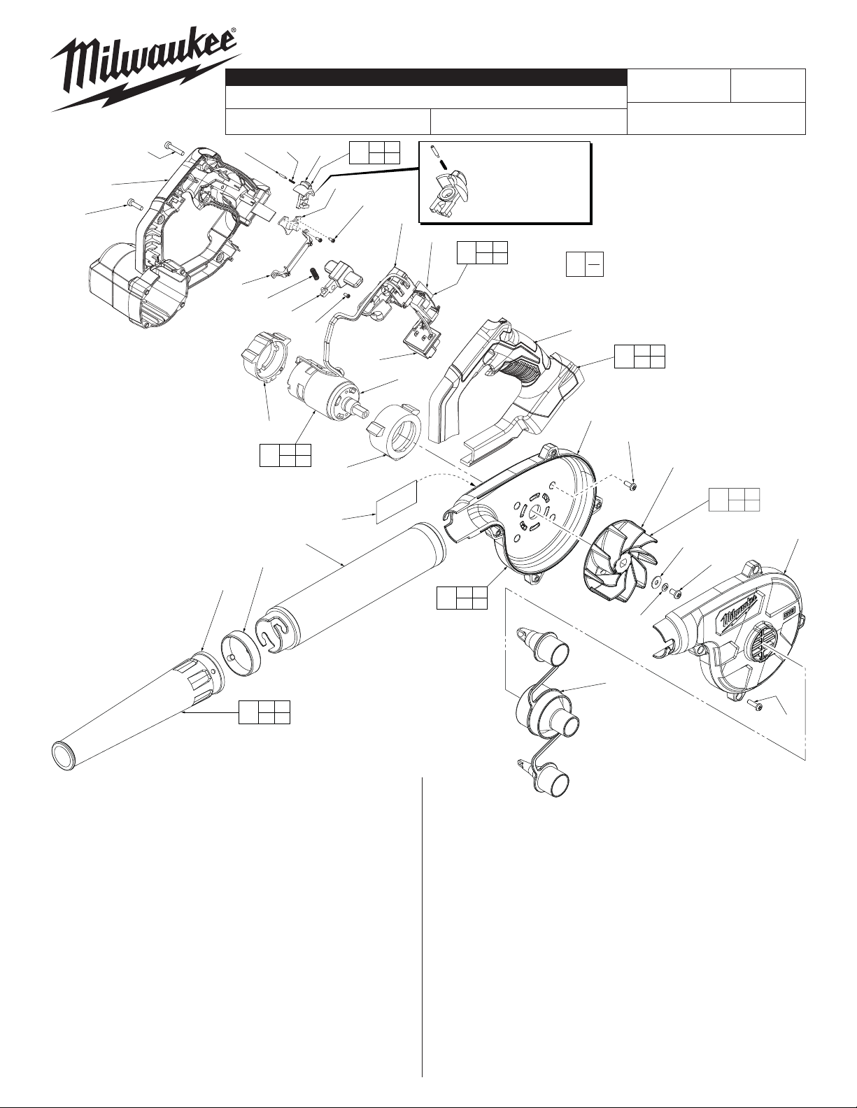
SERVICE PARTS LIST
SPECIFY CATALOG NO. AND SERIAL NO. WHEN ORDERING PARTS
CORDLESS M18™ COMPACT BLOWER
35
14
STARTING
SERIAL NO.
NOTE: Place a little grease
on the Spring #10 and the
Pin #9 to help retain
the parts in the small
cavity of the Speed
37
41
35 36
37 38
F74A
Button
00
12
0
CATALOG NO.
9
33
(1x)
2
10
3
7
6
11
8
0884-20
9 10
39
11
38
4(2x)
36
REVISED BULLETIN
EXAMPLE:
Component Parts (Small #) Are Included
When Ordering The Assembly (Large #).
1 2
40
12 33
54-05-0805
DATE
Nov. 2013
WIRING INSTRUCTION
See Page 2
13
13 14
42
15
17
16
16 17
45
19
FIG. PART NO. DESCRIPTION OF PART NO. REQ.
1 06-81-0016 M3 x 9 Pan Hd. Plastite T-10 Screw (7)
2 --------------- Handle/Motor Housing Halve-Right (1)
3 31-17-0130 Wire Trap (1)
4 06-81-0026 M2.3 x 6 Pan Hd. Plastite Phillips Screw (2)
6 42-42-0805 Switch Lock Button (1)
7 40-50-0206 Switch Lock Spring (1)
8 06-81-0046 M2.3 x 6 Pan Hd. Washer Screw-Phillips (1)
9 --------------- Speed Button Detent Pin (1)
10 --------------- Speed Button Spring (1)
11 --------------- Speed Button (1)
12 --------------- Handle Housing Halve-Left (1)
13 44-34-0450 Lower Motor Support (1)
14 --------------- Motor with Spindle (1)
15 44-34-0455 Upper Motor Support (1)
16 43-24-0510 Nozzle (1)
17 44-90-1040 Nozzle Ring (1)
19 43-24-0155 Extension Tube (1)
20 45-80-0020 Infl ator/Defl ator Valves (1)
21 06-81-0056 M4 x 18 Pan Hd. Plastite T-20 Screw (4)
22 --------------- Fan Housing Halve-Left (1)
23 05-83-0400 M5.0 x 8 Pan Hd. Phillips Machine Screw (1)
24 45-88-0013 Washer (1)
25 --------------- Fan (1)
15
31
19
27
26(4x)
25
23 24
44
25 32
24
23
21 22
43
27 31
32
20
FIG. PART NO. DESCRIPTION OF PART NO. REQ.
26 06-81-0066 M4.0 x 10 Pan Hd. Plastite Phillips Screw (4)
27 --------------- Fan Housing Halve-Right (1)
31 12-20-0884 Service Nameplate (1)
32 06-97-0040 Lock Washer (1)
33 06-81-0017 M3 x 15 Pan Hd. Plastite T-10 Screw (1)
35 --------------- On-Off Switch (1)
36 --------------- Battery Connector Block (1)
37 --------------- Main PCBA (1)
38 --------------- Switch PCBA (1)
39 31-01-1010 Blower Speed Button Assembly (1)
40 14-34-1025 Handle/Motor Housing Assembly (1)
41 14-20-2000 Electronics Assembly
Consists of On-Off Switch, Main PCBA,
PCBA Switch, Battery Terminal Block (1)
42 14-50-1300 Motor Assembly with Spindle (1)
43 14-38-1010 Fan Housing Assembly (1)
44 22-84-0080 Blower Fan Kit (1)
45 43-24-0520 Nozzle/Extension Assembly (1)
MILWAUKEE ELECTRIC TOOL CORPORATION
13135 W. LISBON RD., BROOKFIELD, WI 53005
22
21
(4x)
Drwg. 3
Page 2
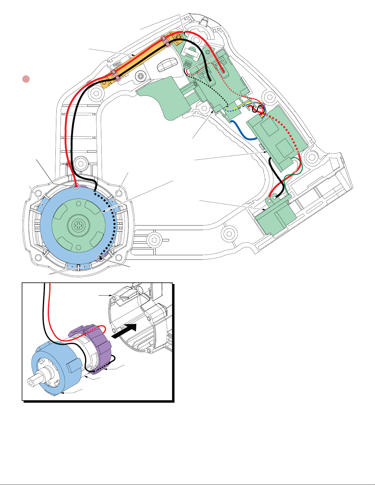
Wire Trap #3
= WIRE TRAPS
or GUIDES
Switch PCBA
AS AN AID TO REASSEMBLY, TAKE
NOTICE OF WIRE ROUTING AND
POSITION IN WIRE GUIDES AND
TRAPS WHILE DISMANTLING TOOL.
BE CAREFUL AND AVOID PINCHING
WIRES BETWEEN HANDLE HALVES
WHEN ASSEMBLING.
Channel in
Lower Motor
Support for
red motor wire
Rubber
lugs
Rubber lugs
#2 Handle/Motor
Housing Halve
#15 Upper
Motor Support
Rubber lugs
#14 Motor
On-Off Switch
Main PCBA
Motor
Battery Terminal
Block
Channel in Lower Motor
Support for black motor wire
#13 Lower
Motor Support
When reinstalling a new Motor Assembly, be sure that the red and black motor
leads are fed through the large opening in the back of the Lower Motor Support
before soldering wires to the On-Off Switch.
Slide the lower motor support onto the rear of the motor, orienting it as shown
and making sure it is firmly pressed into place.
Be sure that the Upper Motor Support is oriented as shown and firmly seated on
the spindle end of the Motor.
Press the motor leads into the channels of the lower motor support and remove
most of the slack from the rear of the motor. Line up the rubber lugs of the upper
and lower motor supports with the channels in the motor cavity of the Handle/
Motor Housing Halve. Install the assembly into the handle/motor housing halve.
NOTE:
For ease of installation, the upper motor support can be left off the spindle end
of the motor until the lower motor support and motor are pressed into place. At
that time, the upper motor support can be assembled onto the motor, orienting
the rubber lugs with the corresponding channels in the motor cavity and firmly
seated.
 Loading...