

Milwaukee 0566-1 Operator's Manual
HEAVY-DUTY DRAIN CLEANER WITH TRIGGER
SPEED CONTROL
DÉBOUCHOIR EXTRA ROBUSTE À VITESSE VARIABLE
HERRAMIENT A PARA T AREAS PESADAS DE LIMPIEZA DE
CAÑOS CON DISPARADOR PARA CONTROLAR LA
VELOCIDAD
TO REDUCE THE RISK OF INJURY , USER MUST READ AND UNDERSTAND
OPERATOR'S MANUAL.
AFIN DE RÉDUIRE LE RISQUE DE BLESSURES, L'UTILISATEUR DOIT LIRE
ET BIEN COMPRENDRE LE MANUEL DE L'UTILISATEUR.
PARA REDUCIR EL RIESGO DE LESIONES, EL USUARIO DEBE LEER Y
ENTENDER EL MANUAL DEL OPERADOR.
Catalog No.
No de Cat.
Catálog No.
0566-1
OPERATOR'S MANUAL
MANUEL DE L'UTILISATEUR
MANUAL DEL OPERADOR
32
POWER TOOL USE AND CARE
16. Do not force the power tool. Use
the correct power tool for your
application. The correct power tool
will do the job better and safer at the
rate for which it was designed.
17. Do not use the power tool if the
switch does not turn it on and off.
Any power tool that cannot be controlled with the switch is dangerous
and must be repaired.
18. Disconnect the plug from the
power source and/or the battery
pack from the power tool before
making any adjustments, changing accessories, or storing
power tools. Such preventive safety
measures reduce the risk of starting
the tool accidentally.
19. Store idle power tools out of the
reach of children and do not allow persons unfamiliar with the
power tools or these instructions
to operate power tools. Power
tools are dangerous in the hands of
untrained users.
20. Maintain power tools. Check for
misalignment or binding of moving parts, breakage of parts and
any other condition that may affect the power tool's operation. If
damaged, have the power tool
repaired before use. Many acci-
dents are caused by poorly maintained
power tools.
21. Keep cutting tools sharp and
clean. Properly maintained cutting
tools with sharp cutting edges are less
likely to bind and are easier to control.
SERVICE
23. Have your power tool serviced by
a qualified repair person using
only identical replacement parts.
This will ensure that the safety of the
power tool is maintained.
WORK AREA SAFETY
ELECTRICAL SAFETY
PERSONAL SAFETY
WARNING!
READ ALL INSTRUCTIONS
Failure to follow all instructions listed below may result in electric shock, fire
and/or serious injury. The term "power tool" in all of the warnings listed
below refers to your mains-operated (corded) power tool or batteryopearted (cordless) power tool.
SAVE THESE INSTRUCTIONS
GENERAL SAFETY RULES-FOR ALL POWER TOOLS
1. Keep work area clean and well lit.
Cluttered or dark areas invite accidents.
2. Do not operate power tools in ex-
plosive atmospheres, such as in
the presence of flammable liquids, gases, or dust. Power tools
create sparks which may ignite the
dust or fumes.
3. Keep children and bystanders
away while operating a power
tool. Distractions can cause you to
lose control.
4. Power tool plugs must match the
outlet. Never modify the plug in
any way. Do not use any adapter
plugs with earthed (grounded)
power tools. Unmodified plugs and
matching outlets will reduce risk of
electric shock.
5. Avoid body contact with earthed
or grounded surfaces such as
pipes, radiators, ranges and refrigerators. There is an increased
risk of electric shock if your body is
earthed or grounded.
6. Do not expose power tools to rain
or wet conditions. Water entering a
power tool will increase the risk of
electric shock.
7. Do not abuse the cord. Never use
the cord for carrying, pulling, or
unplugging the power tool. Keep
cord away from heat, oil, sharp
edges, or moving parts. Damaged
or entangled cords increase the risk
of electric shock.
9. Stay alert, watch what you are do-
ing and use common sense when
operating a power tool. Do not use
a power tool while you are tired
or under the influence of drugs,
alcohol or medication. A moment
of inattention while operating power
tools may result in serious personal
injury.
10. Use safety equipment. Always
wear eye protection. Safety equipment such as dust mask, non-skid
safety shoes, hard hat, or hearing protection used for appropriate conditions
will reduce personal injuries.
11. Avoid accidental starting. Ensure
the switch is in the off-position
before plugging in. Carrying tools
with your finger on the switch or plugging in power tools that have the
switch on invites accidents.
12. Remove any adjusting key or
wrench before turning the power
tool on. A wrench or a key left at-
tached to a rotating part of the power
tool may result in personal injury.
13. Do not overreach. Keep proper
footing and balance at all times.
This enables better control of the
power tool in unexpected situations.
8. When operating a power tool out-
doors, use an extension cord suitable for outdoor use. Use of a cord
suitable for outdoor use reduces the
risk of electric shock.
14. Dress properly. Do not wear loose
clothing or jewellery. Keep your
hair, clothing and gloves away
from moving parts. Loose clothes,
jewellery, or long hair can be caught in
moving parts.
15. If devices are provided for the
connection of dust extraction and
collection facilities, ensure these
are connected and properly used.
Use of these devices can reduce dustrelated hazards.
22. Use the power tool, accessories
and tool bits etc., in accordance
with these instructions and in the
manner intended for the particular type of power tool, taking into
account the working conditions
and the work to be performed.
Use of the power tool for operations
different from those intended could result in a hazardous situation.
54
The grounding prong in the plug is connected through the green wire inside the
cord to the grounding system in the tool.
The green wire in the cord must be the
only wire connected to the tool's grounding system and must never be attached to
an electrically “live” terminal.
Your tool must be plugged into an appropriate outlet, properly installed and
grounded in accordance with all codes and
ordinances. The plug and outlet should look
like those in Figure A.
Double Insulated Tools:
Tools with Two Prong Plugs
Tools marked “Double Insulated” do not require grounding. They have a special
double insulation system which satisfies
OSHA requirements and complies with the
applicable standards of Underwriters Laboratories, Inc., the Canadian Standard Association and the National Electrical Code.
Double Insulated tools may be used in either of the 120 volt outlets shown in
Figures B and C.
Grounded Tools:
Tools with Three Prong Plugs
Tools marked “Grounding Required” have
a three wire cord and three prong grounding plug. The plug must be connected to a
properly grounded outlet (See Figure A). If
the tool should electrically malfunction or
break down, grounding provides a low resistance path to carry electricity away from
the user, reducing the risk of electric shock.
Fig. B
Fig. C
Fig. A
Improperly connecting the
grounding wire can result in the
risk of electric shock. Check
with a qualified electrician if you
are in doubt as to whether the
outlet is properly grounded. Do
not modify the plug provided
with the tool. Never remove the
grounding prong from the plug.
Do not use the tool if the cord or
plug is damaged. If damaged,
have it repaired by a MILWAUKEE
service facility before use. If the
plug will not fit the outlet, have a
proper outlet installed by a qualified electrician.
GROUNDING
WARNING!
Symbology
SPECIFIC SAFETY RULES
1. Maintain labels and nameplates. These carry important information. If unreadable
or missing, contact a MILWAUKEE service facility for a free replacement.
2. WARNING! Some dust created by power sanding, sawing, grinding, drilling, and other
construction activities contains chemicals known to cause cancer, birth defects or
other reproductive harm. Some examples of these chemicals are:
• lead from lead-based paint
• crystalline silica from bricks and cement and other masonry products, and
• arsenic and chromium from chemically-treated lumber.
Your risk from these exposures varies, depending on how often you do this type of
work. To reduce your exposure to these chemicals: work in a well ventilated area,
and work with approved safety equipment, such as those dust masks that are specifically designed to filter out microscopic particles.
Amps
1.6
No Load
RPM
0 - 450
Volts
120
Catalog
Number
0566-1
Specifications
Amperes
Canadian Standards
Association
Underwriters
Laboratories, Inc.
Volts Alternating Current
No Load Revolutions
per Minute (RPM)
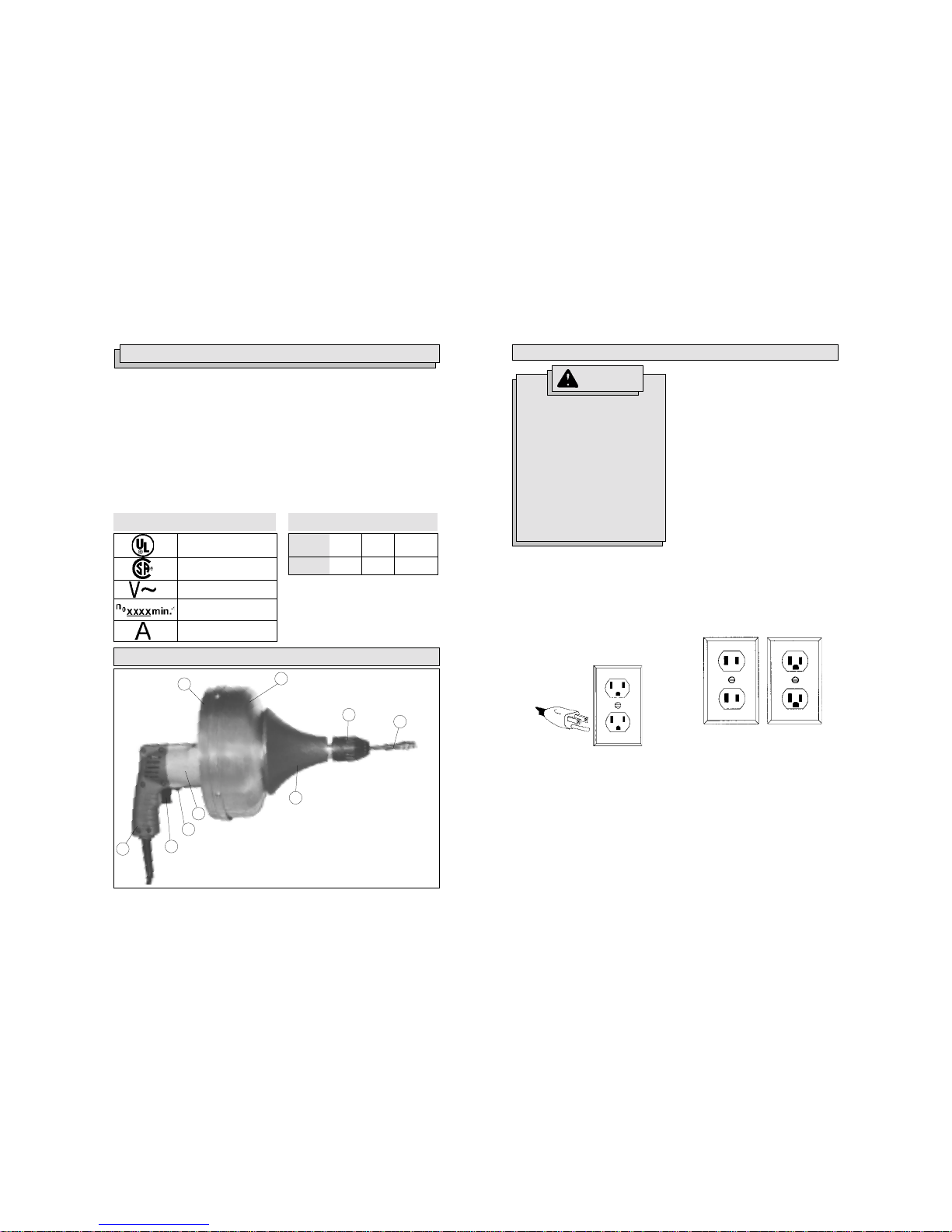
FUNCTIONAL DESCRIPTION
1. Rear drum half
2. Front drum half
3. Jacobs
™
keyless chuck
4. Steel cable
5. Hand grip
6. Motor housing
7. Forward/reverse switch
8. Trigger switch
9. Handle
7
8
1
2
3
4
5
6
9
76
NOTE: To prevent damage to the cable, do not exceed the recommended pipe diameters.
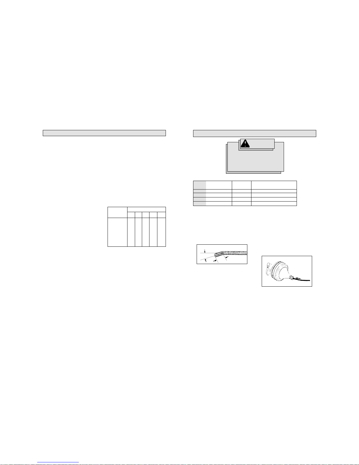
Cable installation
Inserting cable into drum (Fig. 1 & 2)
1. Make a 15° to 30° bend approximately
1 inch from the tail end of the cable
(See Fig. 1). This will aid in seating
the cable into the drum.
Fig. 2
Cable
Size
1/4"
5/16"
5/16"
3/8"
Pipe
Dia.
1 1/4"-1 1/2"
1 1/4"-1 1/2"
1 1/4"-1 1/2"
1 1/2" -2"
Selecting the proper cable
Cable
Style
Steel Coreless
Steel Coreless
Steel Inner-core
Steel Inner Core
Additional Applications
Trap & Drain Lines
Trap & Drain Lines
Trap & Drain Lines"
Drain lines & Boiler Tube Cleaning
TOOL ASSEMBLY
2. Hold the drain cleaner firmly. Loosen
the chuck and insert the cable approximately 10 to 12 inches into the drum
(See Fig. 2). To prevent kinking, insert
the complete cable into the drum, 10 to
12 inches at a time, leaving only the
bulb or the enlarge head exposed.
Fig. 1
1"
15° to 30°
To reduce the risk of injury, always unplug the tool before attaching or removing accessories.
Use only specifically recommended accessories. Others may
be hazardous.
WARNING!
Grounded tools require a three wire extension cord. Double insulated tools can
use either a two or three wire extension
cord. As the distance from the supply outlet increases, you must use a heavier
gauge extension cord. Using extension
cords with inadequately sized wire causes
a serious drop in voltage, resulting in loss
of power and possible tool damage. Refer
to the table shown to determine the required minimum wire size.
The smaller the gauge number of the wire,
the greater the capacity of the cord. For
example, a 14 gauge cord can carry a
higher current than a 16 gauge cord. When
using more than one extension cord to make
up the total length, be sure each cord contains at least the minimum wire size required. If you are using one extension cord
for more than one tool, add the nameplate
amperes and use the sum to determine the
required minimum wire size.
Guidelines for Using Extension Cords
• If you are using an extension cord outdoors, be sure it is marked with the
suffix “W-A” (“W” in Canada) to indicate that it is acceptable for outdoor
use.
• Be sure your extension cord is properly wired and in good electrical
condition. Always replace a damaged
extension cord or have it repaired by
a qualified person before using it.
• Protect your extension cords from
sharp objects, excessive heat and
damp or wet areas.
READ AND SAVE ALL INSTRUCTIONS FOR FUTURE USE.
Recommended Minimum Wire
Gauge for Extension Cords*
Extension Cord Length
* Based on limiting the line voltage drop to
five volts at 150% of the rated amperes.
Nameplate
Amperes
0 - 2.0
2.1 - 3.4
3.5 - 5.0
5.1 - 7.0
7.1 - 12.0
12.1 - 16.0
16.1 - 20.0
25'
18
18
18
18
16
14
12
75'
18
18
16
14
12
10
100'
18
16
14
12
10
150'
16
14
12
12
50'
18
18
18
16
14
12
10
EXTENSION CORDS
98
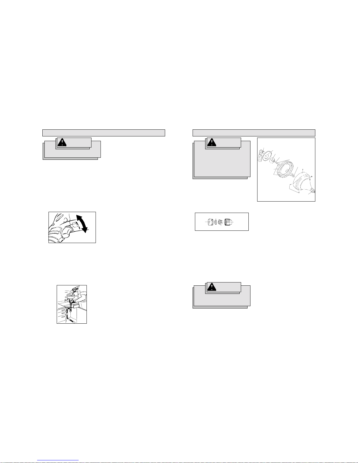
Chuck Maintenance (Fig. 5)
The chuck should be taken apart and
cleaned periodically. Collets should be replaced when worn to assure proper gripping of the cable. Do not use a wrench to
tighten the chuck. If the chuck fails to grip
the cable, either a thorough cleaning job or
a new collet is required.
Lubrication (Fig. 6)
Proper and regular lubrication is an important factor in determining the useful life of
your MILWAUKEE Drain Cleaner.The tool
has been lubricated at the factory and this
lubrication should be sufficient for six
months to one year depending upon the
amount of use the tool receives. Tools used
consistently on heavy duty production jobs
require lubrication more often. Tools that
have not been used for extended periods
of time should be relubricated before being put back into service.
WARNING!
To reduce the risk of injury, always
unplug your tool before
performing any maintenance.
Never disassemble the tool or try
to do any rewiring on the tool's
electrical system. Contact a
MILWAUKEE service facility for
ALL repairs.
To lubricate:
1. Unplug the tool and remove the steel
cable through the chuck.
2. Remove the four perimeter screws
from the drum.
3. Carefully pull the drum halves apart by
grasping the motor housing and the
chuck spindle. Set aside the front drum
half.
4. Remove the 3/8"-24 crown nut, “D”
hole hex washer and the rear drum
half. Set aside the rear drum half and
the parts.
5. Remove the three screws from the
gearcase.
6. With the tool resting on the motor housing, hold the diaphragm firmly against
the motor housing and lightly tap the
gearcase to loosen. If the gearcase
will not dislodge, use two screwdrivers opposite each other to gently pry
apart. If the diaphragm pulls free of
the motor housing, the armature may
dislodge, permitting the brushes to slip
off the commutator. Should this occur,
return the entire tool and all parts to
the nearest MILWAUKEE Service
Center or Authorized Service Station.
7. Clean out old grease and repack the
gearcase two-thirds full with
MILWAUKEE Type “A” grease - 1 lb.
can (Cat. No. 49-08-4121).
8. To assemble, reverse the procedure
described above.
WARNING!
Coiled cable can cause injury and
must be removed before drum is
opened.
MAINTENANCE
Body
Thrust plug
Collet
Sleeve
Fig. 5
Flat washer
Shield
Gear case
Spindle washer
Chuck
spindle
Drum screw
Crown nut
“D” hole
hex washer
Rear drum
half
Motor
housing
Fig. 6
Starting, stopping and controlling
speed
These tools may be used at any speed
from 0 RPM to full speed.
1. To start the tool, pull the trigger.
2. To vary the driving speed, increase or
decrease pressure on the trigger. The
further the trigger is pulled, the greater
the speed.
3. To stop the tool, release the trigger.
Using forward/reverse switch (Fig. 3)
1. For forward (clockwise) rotation,
push the forward/reverse switch to
the left.
2. For reverse (counterclockwise) rotation, push the forward/reverse
switch to the right. Although an interlock prevents reversing the tool while
the motor is running, allow the motor
to come to a full stop before reversing.
Inserting cable into drain (Fig. 4)
1. Set the forward/reverse switch to the
forward position
2. Loosen the chuck and remove 10 to
12 inches of the cable from the drum.
3. Tighten the chuck by hand.
4. Operate the tool at low speed. Continue to feed the cable (steps 2 and 3)
into the drain using a back and forth
motion until the obstruction is cleared.
This procedure keeps the cable rotating and will prevent binding.
NOTE: If the tool binds, stop it immediately.
To unbind drain cleaner
1. Withdraw the tool a few inches while
in reverse to free the cable.
2. Stop the tool.
3. After the tool has come to a complete
stop, switch back to the forward direction.
CAUTION: Extended operation of the tool
in reverse can cause damage to the cable
and accessories.
Removing cable from drain
1. Tighten the chuck. With the tool running slowly in the forward direction,
remove 10 to 12 inches of the cable.
2. Stop the tool. Wash and wipe the exposed cable with a rag. Loosen the
chuck and push the exposed cable into
the drum and retighten the chuck. Repeat steps 1 and 2 as necessary until
all the cable is free of the drain.
3. Before storing the drain cleaner, remove the full length of the cable. Coil it
loosely. Then wash and wipe it with
an oiled rag before returning it to the
drum.
To reduce the risk of injury,
always wear eye protection.
WARNING!
Fig. 4
OPERATION
Reverse
Forward
Fig. 3
1110
WARNING!
To reduce the risk of injury,
electric shock and damage to the
tool, never immerse your tool in
liquid or allow a liquid to flow inside the tool.
Maintaining tools
Keep your tool in good repair by adopting a
regular maintenance program. Before use,
examine the general condition of your tool.
Inspect guards, switches, tool cord set and
extension cord for damage. Check for
loose screws, misalignment, binding of
moving parts, improper mounting, broken
parts and any other condition that may affect its safe operation. If abnormal noise
or vibration occurs, turn the tool off immediately and have the problem corrected before further use. Do not use a damaged
tool. Tag damaged tools “DO NOT USE” until
repaired (see “Repairs”).
Under normal conditions, relubrication is
not necessary until the motor brushes
need to be replaced. After six months to
one year, depending on use, return your
tool to the nearest MILWAUKEE service
facility for the following:
• Lubrication
• Brush inspection and replacement
• Mechanical inspection and cleaning
(gears, spindles, bearings, housing,
etc.)
• Electrical inspection (switch,cord,
armature, etc.)
• Testing to assure proper mechanical
and electrical operation
Cleaning
Clean dust and debris from vents. Keep
the tool handles clean, dry and free of oil
or grease. Use only mild soap and a damp
cloth to clean your tool since certain cleaning agents and solvents are harmful to plastics and other insulated parts. Some of
these include: gasoline, turpentine, lacquer
thinner, paint thinner, chlorinated cleaning
solvents, ammonia and household detergents containing ammonia. Never use flammable or combustible solvents around
tools.
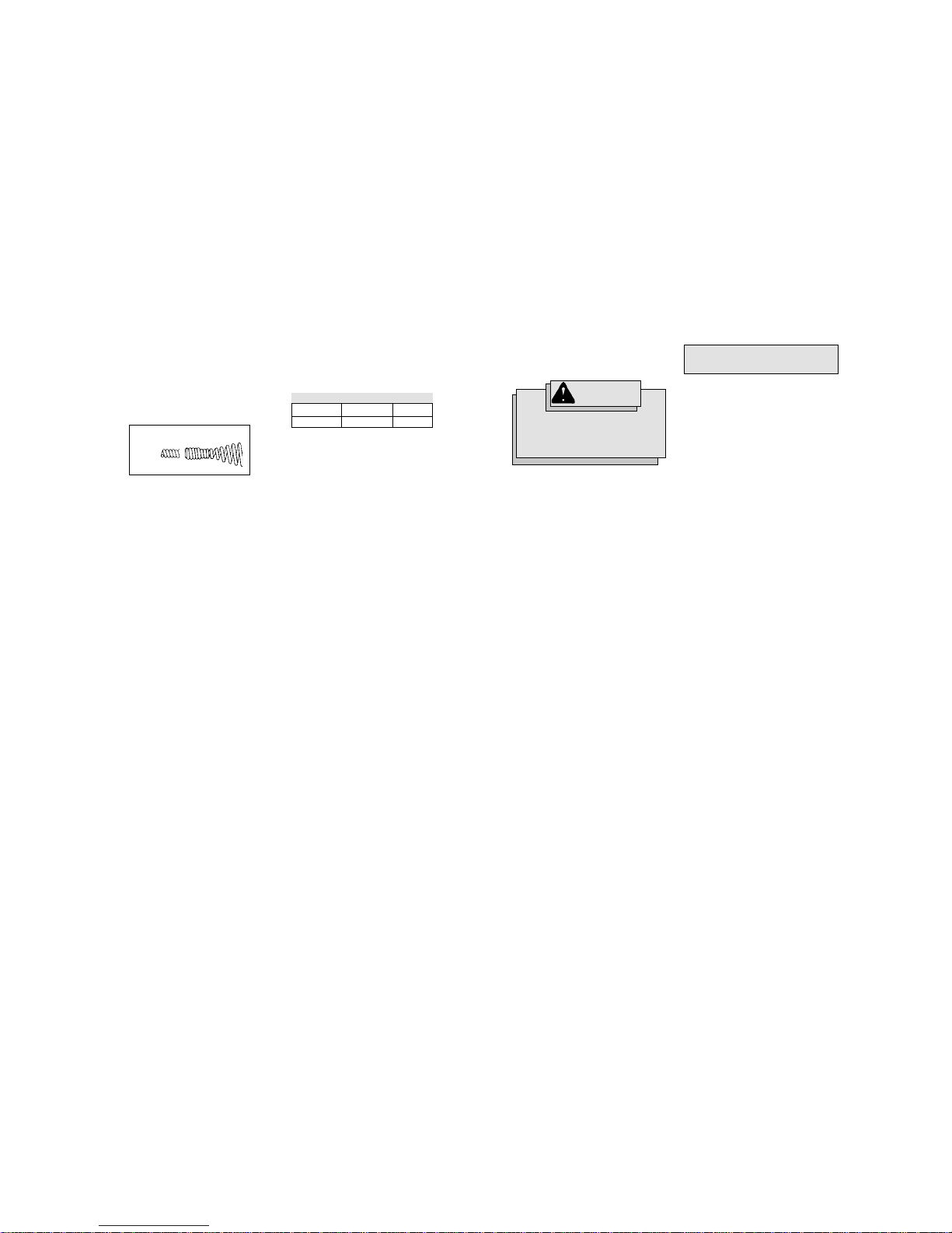
Drill size and depth of drill to be used
in removing plasticore
Repairing kinked or broken cables
(Fig. 7)
Installing replacement bulbs on steel
cables
If the cable becomes kinked, it can be repaired by cutting off the damaged portion
and attaching a replacement bulb.
Core Size
3/8"
5/16"
Drill No.
#206
#33
Depth
(.430)
(.437)
Steel cable
Replacement bulb
Fig. 7
1. To install the replacement bulbs, cut
the cable off below the kinked portion.
2. Grind or file off all burrs remaining on
the cable.
3. Using a screwdriver, slightly spread
apart the coils on the cable. This will
make it easier to thread on the replacement bulb.
4. Manually screw on the replacement
bulb. The bulb end must be facing
away from the coil.
5. Tighten the replacement bulb onto the
steel cable using a pliers or a vice
grips. It is not necessary to weld the
bulb onto the cable since it is a right
hand coiled cable. When pressure is
applied during pipe cleaning, the bulb
tightens on to the cable.
Installing replacement couplings on
core cables
1. Make sure the end of the cable is
ground flat.
2. Place the end of the cable into a vice
so that it extends beyond the vise jaws
by 2 inches. Tighten securely.
3. Drill out the plasticore center using the
proper drill bit (see Drill Size Chart ).
Operate drill with a fast “in and out”
motion until the center of the cable is
clear of plastic to the specified depth
and diameter (see Drill Size Chart).
This generally takes 25-30 seconds.
When clear, tap the end of the cable
several times to knock out any plastic
or metal wire chips.
4. Using a vise grip, thread the coupling
into the drill hole until the shoulder on
the coupling is snug against the face
of the cable.
NOTE: Do not over torque. A flush fit is
all that is required.
FIVE YEAR TOOL
LIMITED WARRANTY
Every MILWAUKEE tool is tested before
leaving the factory and is warranted to be
free from defects in material and workmanship. MILWAUKEE will repair or replace (at MILWAUKEE’s discretion), with-
out charge, any tool (including battery
chargers) which examination proves to be
defective in material or workmanship from
five (5) years after the date of purchase.
Return the tool and a copy of the purchase
receipt or other proof of purchase to a
MILWAUKEE Factory Service/Sales Support Branch location or MILWAUKEE Authorized Service Station, freight prepaid
and insured. This warranty does not cover
damage from repairs made or attempted
by other than MILWAUKEE authorized personnel, abuse, normal wear and tear, lack
of maintenance, or accidents.
Battery Packs, Flashlights, and Radios are
warranted for one (1) year from the date
of purchase.
THE REPAIR AND REPLACEMENT REMEDIES
DESCRIBED HEREIN ARE EXCLUSIVE. IN NO
EVENT SHALL MILWAUKEE BE LIABLE
FOR ANY INCIDENTAL, SPECIAL, OR CONSEQUENTIAL DAMAGES, INCLUDING LOSS
OF PROFITS.
THIS WARRANTY IS EXCLUSIVE AND IN
LIEU OF ALL OTHER WARRANTIES, OR
CONDITIONS, WRITTEN OR ORAL, EXPRESSED OR IMPLIED FOR
MERCHANTABLILITY OR FITNESS FOR
PARTICULAR USE OR PURPOSE.
This warranty gives you specific legal
rights. You may also have other rights that
vary from state to state and province to
province. In those states that do not allow
the exclusion of implied warranties or limitation of incidental or consequential damages, the above limitations or exclusions
may not apply to you. This warranty applies to the United States, Canada, and
Mexico only.
For a complete listing of accessories refer
to your MILWAUKEE Electric Tool catalog
or go on-line to www.milwaukeetool.com.
To obtain a catalog, contact your local distributor or a service center.
Repairs
If your tool is damaged, return the entire
tool to the nearest service center.
 Loading...