

Milwaukee 0301-20 User guide
OPERATOR'S MANUAL
MANUEL de L'UTILISATEUR
MANUAL del OPERADOR
Catalog No.
No de Cat.
Catálogo No.
0100-20 0202-20
0101-20 0299-20
0200-20 0300-20
0201-20 0301-20
0302-20
HEAVY-DUTY DRILLS
EXTRA ROBUSTES PERCEUSES
TALADROS PARA SERVICIO PESADO
TO REDUCE THE RISK OF INJURY, USER MUST READ AND UNDERSTAND
OPERATOR'S MANUAL.
AFIN DE RÉDUIRE LE RISQUE DE BLESSURES, L'UTILISATEUR DOIT LIRE ET
BIEN COMPRENDRE LE MANUEL DE L'UTILISATEUR.
PARA REDUCIR EL RIESGO DE LESIONES, EL USUARIO DEBE LEER Y
ENTENDER EL MANUAL DEL OPERADOR.
GENERAL SAFETY RULES
WARNING!
READ AND UNDERSTAND ALL INSTRUCTIONS
Failure to follow all instructions listed below, may result in
electric shock, fire and/or serious personal injury.
SAVE THESE INSTRUCTIONS
WORK AREA
1. Keep your work area clean and
well lit. Cluttered benches and dark
areas invite accidents.
2. Do not operate power tools in ex-
plosive atmospheres, such as in
the presence of flammable liquids, gases, or dust. Power tools
create sparks which may ignite the dust
or fumes.
3. Keep bystanders, children, and
visitors away while operating a
power tool. Distractions can cause
you to lose control. Protect others in
the work area from debris such as
chips and sparks. Provide barriers or
shields as needed.
ELECTRICAL SAFETY
4. Grounded tools must be plugged
into an outlet properly installed
and grounded in accordance with
all codes and ordinances. Never
remove the grounding prong or
modify the plug in any way. Do not
use any adaptor plugs. Check with
a qualified electrician if you are in
doubt as to whether the outlet is
properly grounded. If the tools
should electrically malfunction or break
down, grounding provides a low resistance path to carry electricity away
from the user.
5. Double Insulated tools are
equipped with a polarized plug
(one blade is wider than the other).
This plug will fit in a polarized outlet only one way. If the plug does
not fit fully in the outlet, reverse
the plug. If it still does not fit, contact a qualified electrician to install
a polarized outlet. Do not change
the plug in any way. Double insula-
tion eliminates the need for the
three wire grounded power cord and
grounded power supply system.
6. Avoid body contact with grounded
surfaces such as pipes, radiators,
ranges and refrigerators. There is
an increased risk of electric shock if
your body is grounded.
7. Do not expose power tools to rain
or wet conditions. Water entering a
power tool will increase the risk of electric shock.
8. Do not abuse the cord. Never use
the cord to carry the tools or pull
the plug from an outlet. Keep cord
away from heat, oil, sharp edges
or moving parts. Replace damaged
cords immediately. Damaged cords
increase the risk of electric shock.
9. When operating a power tool out-
side, use an outdoor extension
cord marked “W-A” or “W”. These
cords are rated for outdoor use and
reduce the risk of electric shock.
PERSONAL SAFETY
10. Stay alert, watch what you are doing, and use common sense when
operating a power tool. Do not use
tool while tired or under the influence of drugs, alcohol, or medication. A moment of inattention while op-
erating power tools may result in serious personal injury.
11. Dress properly. Do not wear loose
clothing or jewelry. Contain long
hair. Keep your hair, clothing, and
gloves away from moving parts.
Loose clothes, jewelry, or long hair can
be caught in moving parts.
2 3
12. Avoid accidental starting. Be sure
switch is off before plugging in.
Carrying tools with your finger on the
switch or plugging in tools with the
switch on invites accidents.
13. Remove adjusting keys or
wrenches before turning the tool
on. A wrench or a key that is left at-
tached to a rotating part of the tool may
result in personal injury.
14. Do not overreach. Keep proper
footing and balance at all times.
Proper footing and balance enables
better control of the tool in unexpected
situations.
15. Use safety equipment. Always
wear eye protection. Dust mask,
non-skid safety shoes, hard hat, or
hearing protection must be used for appropriate conditions.
TOOL USE AND CARE
16. Use clamps or other practical way
to secure and support the workpiece to a stable platform. Holding
the work by hand or against your body
is unstable and may lead to loss of control.
17. Do not force tool. Use the correct
tool for your application. The correct tool will do the job better and safer
at the rate for which it is designed.
18. Do not use tool if switch does not
turn it on or off. Any tool that cannot
be controlled with the switch is dangerous and must be repaired.
19. Disconnect the plug from the
power source before making any
adjustments, changing accessories, or storing the tool. Such pre-
ventive safety measures reduce the
risk of starting the tool accidentally.
20. Store idle tools out of reach of chil-
dren and other untrained persons.
Tools are dangerous in the hands of
untrained users.
21. Maintain tools with care. Keep cut-
ting tools sharp and clean. Properly
maintained tools with sharp cutting edge
are less likely to bind and are easier to
control. Do not use a damaged tool.
Tag damaged tools “Do not use” until
repaired.
22. Check for misalignment or bind-
ing of moving parts, breakage of
parts, and any other condition that
may affect the tool’s operation. If
damaged, have the tool serviced
before using. Many accidents are
caused by poorly maintained tools.
23. Use only accessories that are rec-
ommended by the manufacturer
for your model. Accessories that may
be suitable for one tool, may become
hazardous when used on another tool.
SERVICE
24. Tool service must be performed
only by qualified repair personnel.
Service or maintenance performed by
unqualified personnel could result in a
risk of injury.
25. When servicing a tool, use only
identical replacement parts.
Follow instructions in the Maintenance section of this manual. Use
of unauthorized parts or failure to follow Maintenance Instructions may create a risk of electric shock or injury.
SPECIFIC SAFETY RULES
1. Hold tool by insulated gripping surfaces when performing an operation where
the cutting tool may contact hidden wiring or its own cord. Contact with a “live”
wire will make exposed metal parts of tool “live” and shock the operator.
2. Maintain labels and nameplates. These carry important information. If
unreadable or missing, contact a
3. WARNING! Some dust created by power sanding, sawing, grinding, drilling, and other
construction activities contains chemicals known to cause cancer, birth defects or
other reproductive harm. Some examples of these chemicals are:
• lead from lead-based paint
• crystalline silica from bricks and cement and other masonry products, and
• arsenic and chromium from chemically-treated lumber.
Your risk from these exposures varies, depending on how often you do this type of
work. To reduce your exposure to these chemicals: work in a well ventilated area, and
work with approved safety equipment, such as those dust masks that are specifically
designed to filter out microscopic particles.
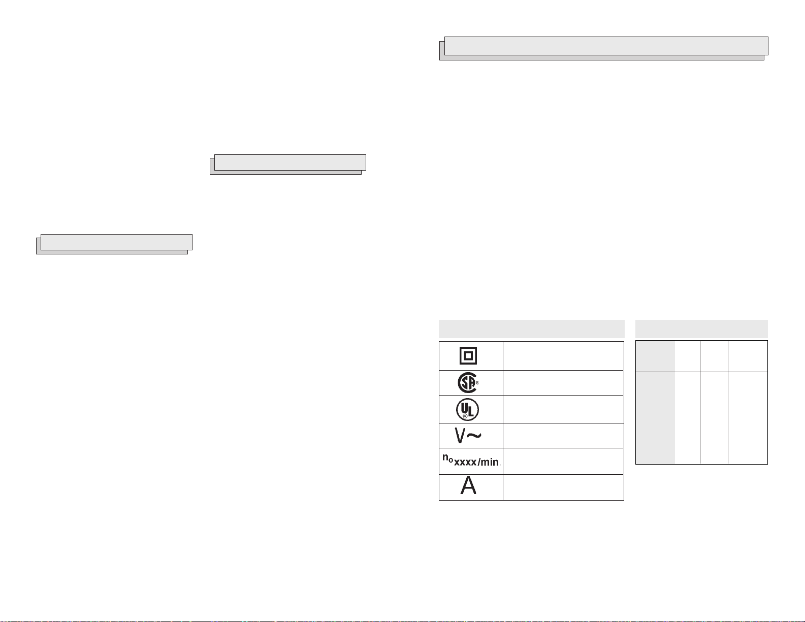
Symbology
Double Insulated
Canadian Standards
Association
Underwriters
Laboratories, Inc.
Volts Alternating Current
No Load Revolutions
per Minute (RPM)
Amperes
MILWAUKEE
service facility for a free replacement.
Specifications
Catalog
No.
0100-20
0101-20
0200-20
0201-20
0202-20
0299-20
0300-20
0301-20
0302-20
Volts
AC
120
120
120
120
120
120
120
120
120
Amps
7.0
7.0
7.0
7.0
7.0
8.0
8.0
8.0
8.0
No Load
RPM
0 - 2500
0 - 4000
0 - 1200
0 - 2500
0 - 1200
0 - 850
0 - 850
0 - 850
0 - 850
4 5
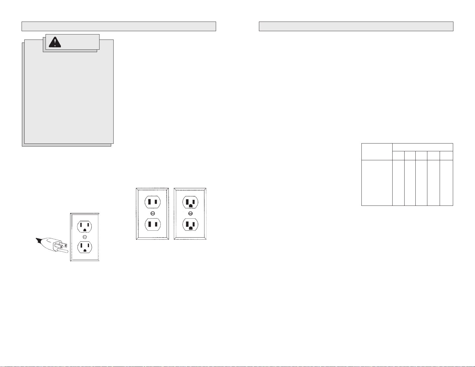
GROUNDING
EXTENSION CORDS
WARNING!
Improperly connecting the
grounding wire can result in the
risk of electric shock. Check
with a qualified electrician if you
are in doubt as to whether the
outlet is properly grounded. Do
not modify the plug provided
with the tool. Never remove the
grounding prong from the plug.
Do not use the tool if the cord or
plug is damaged. If damaged,
have it repaired by a
service facility before use. If the
plug will not fit the outlet, have a
proper outlet installed by a qualified electrician.
Grounded Tools:
Tools with Three Prong Plugs
Tools marked “Grounding Required” have
a three wire cord and three prong grounding plug. The plug must be connected to a
properly grounded outlet (See Figure A). If
the tool should electrically malfunction or
break down, grounding provides a low resistance path to carry electricity away from
the user, reducing the risk of electric shock.
MILWAUKEE
The grounding prong in the plug is connected through the green wire inside the
cord to the grounding system in the tool.
The green wire in the cord must be the
only wire connected to the tool's grounding system and must never be attached to
an electrically “live” terminal.
Your tool must be plugged into an appropriate outlet, properly installed and
grounded in accordance with all codes and
ordinances. The plug and outlet should look
like those in Figure A.
Double Insulated Tools:
Tools with Two Prong Plugs
T ools marked “Double Insulated” do not require grounding. They have a special
double insulation system which satisfies
OSHA requirements and complies with the
applicable standards of Underwriters Laboratories, Inc., the Canadian Standard Association and the National Electrical Code.
Double Insulated tools may be used in either of the 120 volt outlets shown in
Figures B and C.
Grounded tools require a three wire extension cord. Double insulated tools can
use either a two or three wire extension
cord. As the distance from the supply outlet increases, you must use a heavier
gauge extension cord. Using extension
cords with inadequately sized wire causes
a serious drop in voltage, resulting in loss
of power and possible tool damage. Refer
to the table shown to determine the required minimum wire size.
The smaller the gauge number of the wire,
the greater the capacity of the cord. For
example, a 14 gauge cord can carry a
higher current than a 16 gauge cord. When
using more than one extension cord to make
up the total length, be sure each cord contains at least the minimum wire size required. If you are using one extension cord
for more than one tool, add the nameplate
amperes and use the sum to determine the
required minimum wire size.
Guidelines for Using Extension Cords
• If you are using an extension cord outdoors, be sure it is marked with the
suffix “W-A” (“W” in Canada) to indicate that it is acceptable for outdoor
use.
• Be sure your extension cord is properly wired and in good electrical
condition. Always replace a damaged
extension cord or have it repaired by a
qualified person before using it.
• Protect your extension cords from
sharp objects, excessive heat and
damp or wet areas.
Recommended Minimum Wire
Gauge for Extension Cords*
Nameplate
Amperes
0 - 2.0
2.1 - 3.4
3.5 - 5.0
5.1 - 7.0
7.1 - 12.0
12.1 - 16.0
16.1 - 20.0
* Based on limiting the line voltage drop to
five volts at 150% of the rated amperes.
Extension Cord Length
25'
18
18
18
18
16
14
12
50'
18
18
18
16
14
12
10
75'
18
18
16
14
12
10
100'
18
16
14
12
10
150'
16
14
12
12
Fig. A
Fig. B
6 7
Fig. C
READ AND SA VE ALL INSTRUCTIONS FOR FUTURE USE.
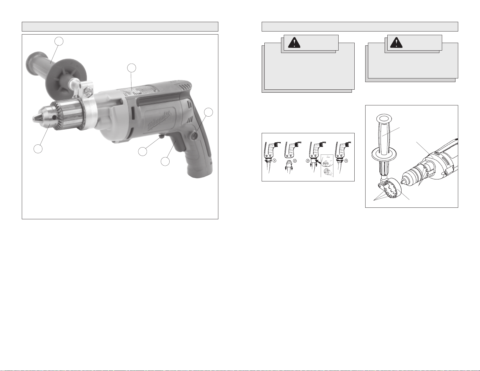
FUNCTIONAL DESCRIPTION
TOOL ASSEMBLY
2
3
1
1. Chuck
2. Side handle*
3. Nameplate
4. Lock button
5. Trigger
6. Forward/Reverse switch
* Cat. Nos. 0200-20, 0202-20, 0299-20, 0300-20,
0301-20, 0302-20 only
WARNING!
To reduce the risk of injury,
always unplug tool before attaching or removing accessories
or making adjustments. Use only
specifically recommended accessories. Others may be hazardous.
Removing and Replacing Quik-Lok
Cords (Fig. 1) (Cat. No. 0100-20,
4
6
5
0101-20, 0202-20, 0301-20, 0302-20
MILWAUKEE
provide instant field replacement or
substitution.
Fig. 1
1. T o remove the Quik-Lok® Cord, turn the
cord nut 1/4 turn to the left and pull it
out.
2. T o replace the Quik-Lok® Cord, align the
connector keyways and push the connector in as far as it will go. Turn the
cord nut 1/4 turn to the right to lock.
's exclusive Quik-Lok® Cords
To reduce the risk of injury, always use a side handle when using this tool. Always brace and
hold securely.
Adjusting the Side Handle (Fig. 2)
(Cat. No. 0200-20, 0202-20, 0299-20,
®
0300-20, 0301-20, 0302-20)
Fig. 2
Locking keys
1. Turn the side handle counterclockwise
to loosen.
2. Slide the side handle assembly forward
over the chuck and rotate to the desired angle.
3. Slide the side handle back to the
gearcase and position the locking keys
into the detents. The locking keys help
prevent the handle from slipping.
NOTE: The side handle ring must clear
the chuck.
4. Turn the side handle clockwise to
tighten.
NOTE: Always use the side handle for
best control.
W ARNING!
Side handle
Gearcase
Detents
Side handle ring
8 9
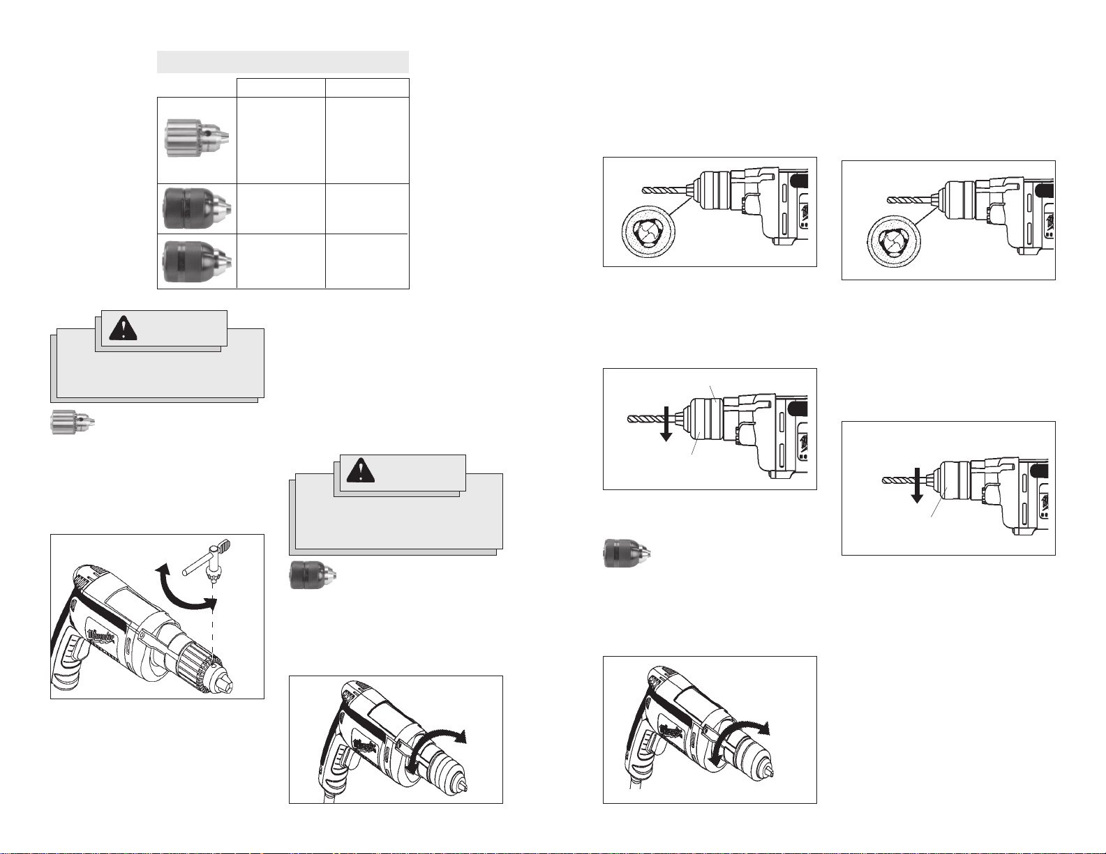
CHUCK IDENTIFICATION
Chuck Type
Keyed
Drill Cat. No.
0100-20
0101-20
0200-20
0299-20
0300-20
0301-20
Be sure the bit shank and chuck jaws
are clean. Dirt particles may prevent
the bit from lining up properly.
2. When using drill bits, insert the bit into
the chuck. Center the bit in the chuck
jaws and lift it about 1/16" off of the
bottom. Tighten the chuck jaws by hand
to align the bit (Fig. 5).
Fig. 5
Be sure the bit shank and chuck jaws
are clean. Dirt particles may prevent
the bit from lining up properly.
2. When using drill bits, insert the bit into
the chuck. Center the bit in the chuck
jaws and lift it about 1/16" off of the
bottom. Tighten the chuck jaws by hand
to align the bit (Fig. 8).
Fig. 8
Double sleeve
Keyless
Single sleeve
Keyless
Installing and Removing Bits
WARNING!
To reduce the risk of injury, always remove the chuck key from
the chuck after each use.
Keyed Chuck (Fig. 3)
These tools are equipped with a chuck tightened using a key. Always unplug the tool
before installing or removing bits.
1. To open the chuck jaws, place the
chuck key in one (1) of the three (3)
holes located on the chuck. Turn the
key counterclockwise (Fig. 3).
Fig. 3
Be sure the bit shank and chuck jaws
are clean. Dirt particles may prevent
the bit from lining up properly.
2. When using drill bits, insert the bit into
the chuck. Center the bit in the chuck
jaws and lift it about 1/16" off of the
bottom. Tighten the chuck jaws by hand
to align the bit.
Loosen
Tighten
0201-20
0202-20
0302-20
When using screwdriver bits, insert the
bit far enough for the chuck jaws to
grip the bit shank. Tighten the chuck
jaws by hand to align the bit.
3. To close the chuck jaws, place the
chuck key in each of the three holes in
the chuck. Turn the chuck key clockwise (Fig. 3). Tighten securely.
4. To remove the bit, insert the chuck key
into one of the holes in the chuck. Turn
the chuck key counterclockwise.
When using screwdriver bits, insert the
bit far enough for the chuck jaws to
grip the bit shank. Tighten the chuck
jaws by hand to align the bit.
3. To close the chuck jaws, hold the collar
and turn the sleeve clockwise
(Fig. 6). Tighten securely.
Fig. 6
Collar
To close
Sleeve
W ARNING!
To reduce the risk of injury, do not
grasp the bit while the chuck is
rotating or while the bit is falling
from the chuck.
Double Sleeve Keyless
Chuck (Fig. 4, 5, & 6)
These tools are equipped with a hand tightening keyless chuck. Always unplug the
tool before installing or removing bits.
1. To open the chuck jaws, hold the collar
and turn the sleeve counterclockwise
(Fig. 4).
Fig. 4
Tighten
Loosen
10 11
4. To remove the bit, hold the chuck collar
and turn the sleeve counterclockwise
to release the bit from the chuck jaws.
Single Sleeve Keyless Chuck
(Fig. 7, 8, & 9)
These tools are equipped with a spindlelock mechanism and a single-sleeve keyless chuck. Always unplug the tool before
inserting or removing bits.
1. To open the chuck jaws, turn the chuck
sleeve counterclockwise (Fig. 7).
Fig. 7
Tighten
Loosen
When using screwdriver bits, insert the
bit far enough for the chuck jaws to
grip the bit shank. Tighten the chuck
jaws by hand to align the bit.
3. To close the chuck jaws, turn the chuck
sleeve clockwise (Fig. 9). Tighten securely. Several detents will be felt as
the chuck sleeve is turned.
NOTE: If the spindle rotates when
opening or closing the chuck jaws,
Fig. 9
To close
Sleeve
grasp the chuck and slightly rotate back
and forth to engage the spindle-lock
mechanism.
The spindle will remain locked until the
tool is turned on. The spindle-lock
mechanism will automatically disengage when the tool is turned on.
4. T o remove the bit, turn the chuck sleeve
counterclockwise to release the bit
from the chuck jaws.
OPERATION
APPLICATIONS
WARNING!
To reduce the risk of injury, wear
safety goggles or glasses with
side shields. Unplug the tool before changing accessories or
making adjustments.
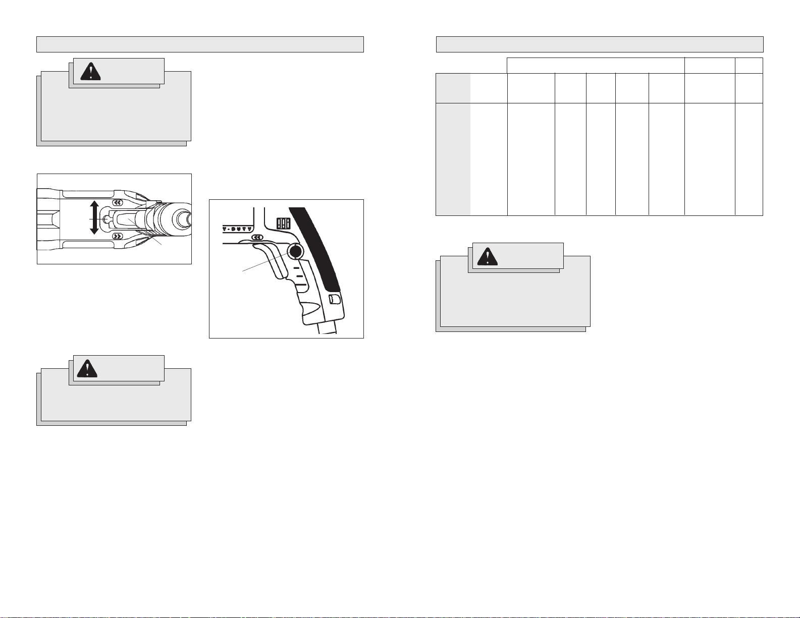
Using Forward/Reverse Switch
(Fig. 10)
Fig. 10
Switch
1. For forward (clockwise) rotation, push
the forward/reverse switch to the left
position as shown.
2. For reverse (counterclockwise) rotation, push the forward/reverse switch
to the right position as shown. Although
an interlock prevents reversing the tool
while the motor is running, allow it to
come to a full stop before reversing.
Forward
Reverse
Trigger
WARNING!
To reduce the risk of injury, keep
hands and cord away from the bit
and all moving parts.
Auger
Bits
NR
NR
1"
7/8"
1"
1-1/2"
1-1/2"
1-1/2"
1-1/2"
Wood
Hole
Saws
NR
NR
3-1/4"
2-1/4"
3-1/4"
3-5/8"
3-5/8"
3-5/8"
3-5/8"
Starting, Stopping and Controlling
Speed
1. To start the tool, pull the trigger.
2. To stop the tool, release the trigger.
3. To vary the drilling speed, simply increase or decrease pressure on the
trigger. The further the trigger is pulled,
the greater the speed.
Locking Trigger (Fig. 11)
The lock button holds the trigger in the ON
position for continuous full speed use.
Fig. 11
Cat.
No Load
No.
0100-20
0101-20
0200-20
0201-20
0202-20
0299-20
0300-20
0301-20
0302-20
NR = Not recommended
0 - 2500
0 - 4000
0 - 1200
0 - 2500
0 - 1200
0 - 850
0 - 850
0 - 850
0 - 850
Flat Boring
RPM
Bits
1-1/2"
1-1/4"
1-1/2"
1-1/2"
1-1/2"
1-1/2"
1-1/2"
1-1/2"
1-1/2"
WARNING!
Lock
button
1. To lock the trigger, hold the lock button
in while pulling the trigger. Release the
trigger.
2. To unlock the trigger, pull the trigger
and release. The lock button will pop
out.
12 13
To reduce the risk of explosion,
electric shock and property damage, always check the work area
for hidden pipes and wires
before drilling.
Selecting Bits
When selecting a bit, use the right type for
your job. For best performance, always
use sharp bits.
Drilling
1. Before drilling, be sure the workpiece
is clamped securely. Use backing material to prevent damage to the workpiece during breakthrough.
2. When starting a hole, place the drill bit
on the work surface and apply firm
pressure. Begin drilling at a slow speed,
gradually increasing the speed as you
drill.
3. Always apply pressure in line with the
bit. Use enough pressure to keep the
drill biting, but do not push hard enough
to stall the motor.
4. Reduce pressure and ease the bit
through the last part of the hole. While
the tool is still running, pull the bit out of
the hole to prevent jamming.
Wood/Steel
NR
NR
NR
NR
NR
Path-
finder
Bits
NR
NR
1-1/4"
1-1/4"
1-1/4"
1-1/4"
1-1/4"
1-1/4"
1-1/4"
TM
Twist
Bits
1/4"
1/4"
1/2"
1/2"
1/2"
3/4"
3/4"
3/4"
3/4"
Selffeed
Bits
2-9/16"
2-9/16"
2-9/16"
2-9/16"
Drilling in Wood, Composition Materials and Plastic
When drilling in wood, composition materials and plastic, start the drill slowly, gradually increasing speed as you drill. When
using twist drill bits, pull the bit out of the
hole frequently to clear chips from the bit
flutes. Use low speeds for plastics with a
low melting point.
Drilling in Masonry
When drilling in masonry, use high speed
carbide-tipped bits. Drilling soft masonry
materials such as cinder block requires little
pressure. Hard materials like concrete require more pressure. A smooth, even flow
of dust indicates the proper drilling rate.
Do not let the bit spin in the hole without
cutting. Do not use water to settle dust or
to cool bit. Both actions will damage the
carbide.
Drilling in Metal
When drilling in metal, use high speed steel
twist drills or hole saws. Use slow speeds
for hard metals and high speeds for softer
metals. Lubricate drill bits with cutting oil
when drilling in iron or steel. Use a coolant
when drilling in nonferrous metals such as
copper, brass or aluminum. Back the material to prevent binding and distortion on
breakthrough.
Steel
Hole
Saws
NR
NR
1-5/8"
NR
1-5/8"
2"
2"
2"
2"
Driving Screws
When driving screws, use the proper
screwdriver bit for your job. After drilling
pilot and shank holes, start the screw
slowly and increase the speed as driving
progresses. Set the screw by slowing to
a stop. Do not run screws down at excessive speeds. To remove screws, reverse
the motor.
Stalling
If the tool seems as if it is about to stall,
maintain a firm grip and reduce pressure
slightly to allow the bit to regain speed. If
the tool does stall, release the trigger immediately. Reverse the motor, remove the
bit from the work and start again. Do not
pull the trigger on and off in an attempt to
start a stalled drill. This can damage the
drill.
WARNING!
High rotational force. To reduce
the risk of injury, always hold or
brace securely. Always use side
handle on tools rated 1200 rpm or
less.
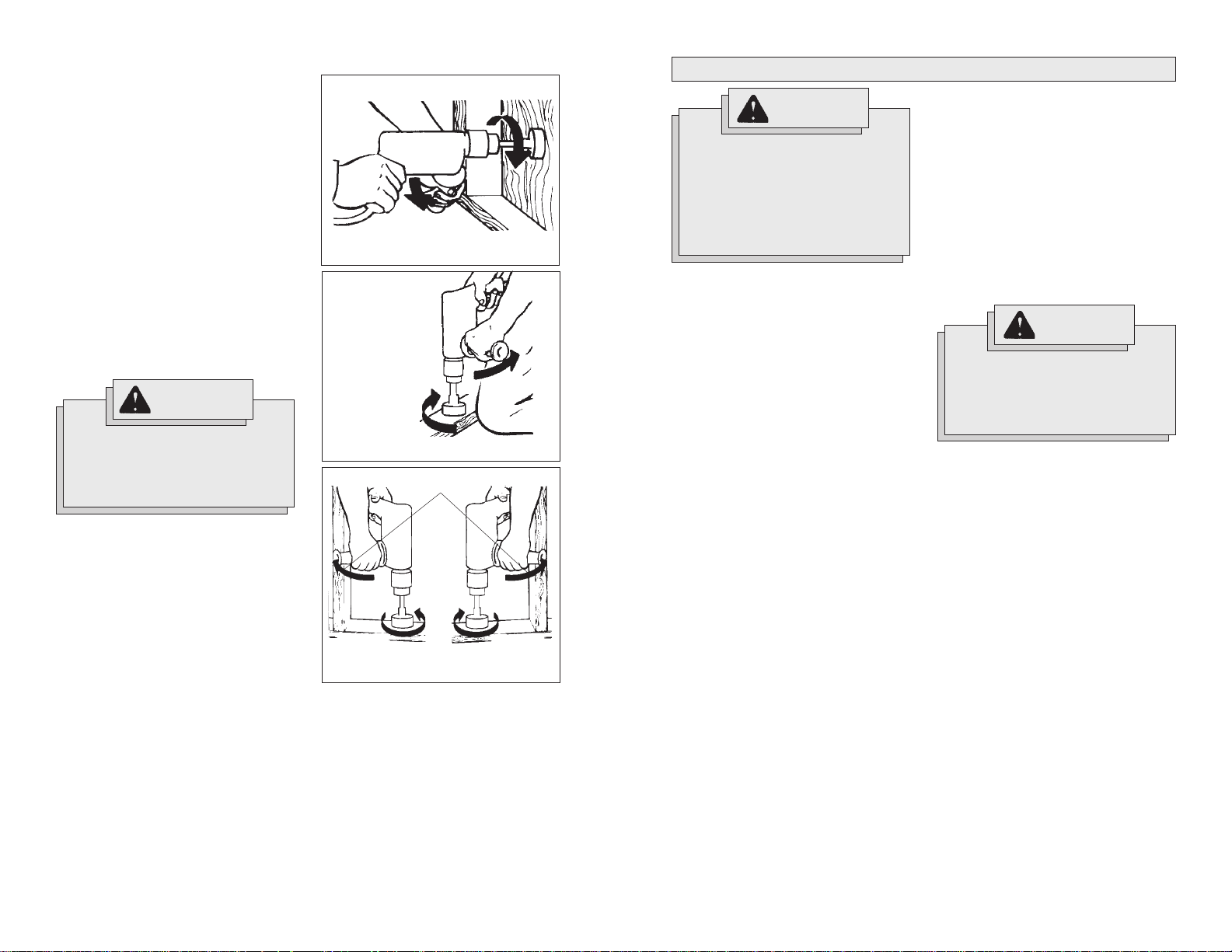
Bit Binding
A high rotational force occurs when a bit
binds. If the bit binds, the tool will be forced
in the opposite direction of the bit rotation
(See Fig. 12-14). Bits may bind if they are
misaligned or when they are breaking
through a hole. Wood boring bits can also
bind if they run into nails or knots. Be prepared for bit binding situations.
To reduce the chance of bit binding:
• Use sharp bits. Sharp bits are less likely
to bind when drilling.
• Use the proper bit for the job. There are
bits that are designed for specific
purposes.
• Use caution when drilling pitchy , knotty,
wet or warped material or when drilling in material that may contain nails.
Typical Bracing Methods
Fig. 12
Reaction
Bracing against the floor
Fig. 13
Forward
rotation
Bracing against your leg
Fig. 14
Reverse rotation
Bracing against a stud
Forward rotation
Reaction
Forward rotation
Reaction
MAINTENANCE
WARNING!
To reduce the risk of injury, always unplug your tool before
performing any maintenance.
Never disassemble the tool or try
to do any rewiring on the tool's
electrical system. Contact a
MILWAUKEE
ALL repairs.
Maintaining Tools
Keep your tool in good repair by adopting a
regular maintenance program. Before use,
examine the general condition of your tool.
Inspect guards, switches, tool cord set and
extension cord for damage. Check for
loose screws, misalignment, binding of
moving parts, improper mounting, broken
parts and any other condition that may affect its safe operation. If abnormal noise
or vibration occurs, turn the tool off immediately and have the problem corrected
before further use. Do not use a damaged
tool. T ag damaged tools “DO NOT USE” until
repaired (see “Repairs”).
Under normal conditions, relubrication is
not necessary until the motor brushes
need to be replaced. After six months to
one year, depending on use, return your
tool to the nearest
facility for the following:
• Lubrication
• Brush inspection and replacement
• Mechanical inspection and cleaning
(gears, spindles, bearings, housing,
etc.)
• Electrical inspection (switch, cord,
armature, etc.)
• Testing to assure proper mechanical
and electrical operation
service facility for
MILWAUKEE
service
Cleaning
Clean dust and debris from vents. Keep
the tool handles clean, dry and free of oil
or grease. Use only mild soap and a damp
cloth to clean your tool since certain cleaning agents and solvents are harmful to plastics and other insulated parts. Some of
these include: gasoline, turpentine, lacquer
thinner, paint thinner, chlorinated cleaning
solvents, ammonia and household detergents containing ammonia. Never use flammable or combustible solvents around
tools.
W ARNING!
To reduce the risk of injury, electric shock and damage to the tool,
never immerse your tool in liquid
or allow a liquid to flow inside the
tool.
Repairs
If your tool is damaged, return the entire
tool to the nearest service center listed on
the back cover of this operator’s manual.
14 15
 Loading...