

Page 1
Catalog No.
No de Catalogue
Catálogo No.
0233-20
0234-1
OPERATOR'S MANUAL
MANUEL DE L'UTILISATEUR
MANUAL DEL OPERADOR
0234-6
0235-21
0235-6
0236-6
0244-1
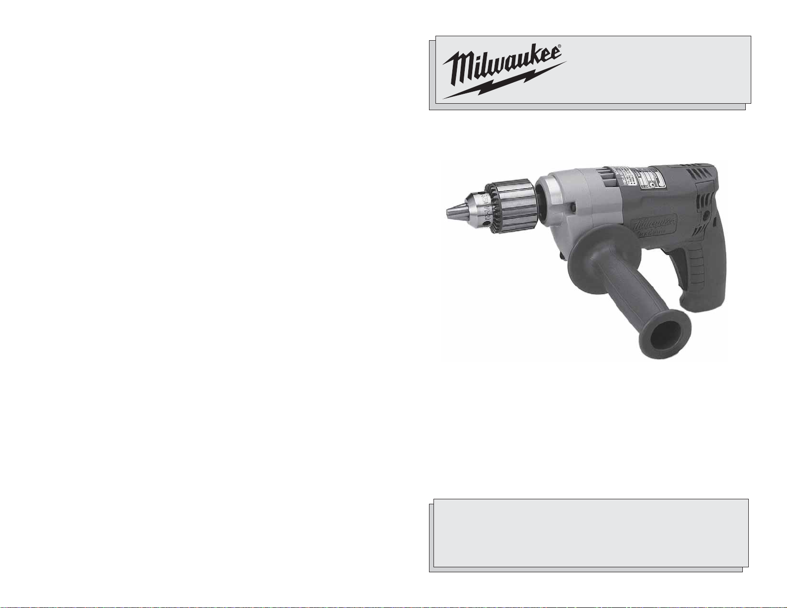
HEAVY-DUTY MAGNUM DRILLS
EXTRA ROBUSTE PERCEUSES MAGNUM
T ALADROS MAGNUM HEAVY-DUTY
TO REDUCE THE RISK OF INJURY, USER MUST READ AND UNDERSTAND
OPERAT OR'S MANUAL.
AFIN DE RÉDUIRE LE RISQUE DE BLESSURES, L'UTILISATEUR DOIT LIRE ET
BIEN COMPRENDRE LE MANUEL DE L'UTILISA TEUR.
PARA REDUCIR EL RIESGO DE LESIONES, EL USUARIO DEBE LEER Y ENTENDER
EL MANUAL DEL OPERADOR.
Page 2
GENERAL SAFETY RULES-FOR ALL POWER TOOLS
WARNING!
READ ALL INSTRUCTIONS
Failure to follow all instructions listed below may result in electric shock, fire
and/or serious injury. The term "power tool" in all of the warnings listed
below refers to your mains-operated (corded) power tool or batteryopearted (cordless) power tool.
SAVE THESE INSTRUCTIONS
WORK AREA SAFETY
1. Keep work area clean and well lit.
Cluttered or dark areas invite accidents.
2. Do not operate power tools in ex-
plosive atmospheres, such as in
the presence of flammable liquids, gases, or dust. Power tools
create sparks which may ignite the dust
or fumes.
3. Keep children and bystanders
away while operating a power tool.
Distractions can cause you to lose
control.
ELECTRICAL SAFETY
4. Power tool plugs must match the
outlet. Never modify the plug in any
way. Do not use any adapter plugs
with earthed (grounded) power
tools. Unmodified plugs and matching
outlets will reduce risk of electric shock.
5. Avoid body contact with earthed
or grounded surfaces such as
pipes, radiators, ranges and refrigerators. There is an increased
risk of electric shock if your body is
earthed or grounded.
6. Do not expose power tools to rain
or wet conditions. Water entering a
power tool will increase the risk of
electric shock.
7. Do not abuse the cord. Never use
the cord for carrying, pulling, or
unplugging the power tool. Keep
cord away from heat, oil, sharp
edges, or moving parts. Damaged
or entangled cords increase the risk of
electric shock.
8. When operating a power tool out-
doors, use an extension cord suitable for outdoor use. Use of a cord
suitable for outdoor use reduces the
risk of electric shock.
PERSONAL SAFETY
9. Stay alert, watch what you are do-
ing and use common sense when
operating a power tool. Do not use
a power tool while you are tired or
under the influence of drugs, alcohol or medication. A moment of
inattention while operating power tools
may result in serious personal injury.
10. Use safety equipment. Always
wear eye protection. Safety equipment such as dust mask, non-skid
safety shoes, hard hat, or hearing protection used for appropriate conditions
will reduce personal injuries.
11. Avoid accidental starting. Ensure
the switch is in the off-position
before plugging in. Carrying tools
with your finger on the switch or plugging in power tools that have the
switch on invites accidents.
12. Remove any adjusting key or
wrench before turning the power
tool on. A wrench or a key left at-
tached to a rotating part of the power
tool may result in personal injury.
13. Do not overreach. Keep proper
footing and balance at all times.
This enables better control of the
power tool in unexpected situations.
14. Dress properly. Do not wear loose
clothing or jewellery. Keep your
hair, clothing and gloves away from
moving parts. Loose clothes,
jewellery, or long hair can be caught in
moving parts.
15. If devices are provided for the
connection of dust extraction and
collection facilities, ensure these
are connected and properly used.
Use of these devices can reduce dustrelated hazards.
POWER TOOL USE AND CARE
16. Do not force the power tool. Use
the correct power tool for your application. The correct power tool will
do the job better and safer at the rate
for which it was designed.
17. Do not use the power tool if the
switch does not turn it on and off.
Any power tool that cannot be controlled with the switch is dangerous
and must be repaired.
18. Disconnect the plug from the
power source and/or the battery
pack from the power tool before
making any adjustments, changing accessories, or storing power
tools. Such preventive safety mea-
sures reduce the risk of starting the
tool accidentally.
19. Store idle power tools out of the
reach of children and do not allow persons unfamiliar with the
power tools or these instructions
to operate power tools. Power
tools are dangerous in the hands of
untrained users.
20. Maintain power tools. Check for
misalignment or binding of moving parts, breakage of parts and
any other condition that may affect the power tool's operation. If
damaged, have the power tool
repaired before use. Many acci-
dents are caused by poorly maintained
power tools.
21. Keep cutting tools sharp and
clean. Properly maintained cutting
tools with sharp cutting edges are less
likely to bind and are easier to control.
22. Use the power tool, accessories
and tool bits etc., in accordance
with these instructions and in the
manner intended for the particular type of power tool, taking into
account the working conditions
and the work to be performed. Use
of the power tool for operations different from those intended could result in
a hazardous situation.
SERVICE
23. Have your power tool serviced by
a qualified repair person using
only identical replacement parts.
This will ensure that the safety of the
power tool is maintained.
SPECIFIC SAFETY RULES
1. Hold power tools by insulated grip-
ping surfaces when performing an
operation where the cutting tool
may contact hidden wiring or its
own cord. Contact with a “live” wire
will make exposed metal parts of the
tool “live” and shock the operator.
2. Use auxiliary handles supplied
with the tool. Loss of control can
cause personal injury.
3. Wear ear protectors with impact
drills. Exposure to noise can cause
hearing loss.
4. Maintain labels and nameplates.
These carry important information. If unreadable or missing, contact a MILWAU-
KEE service facility for a free replacement.
5. WARNING! Some dust created by power
sanding, sawing, grinding, drilling, and
other construction activities contains
chemicals known to cause cancer, birth
defects or other reproductive harm.
Some examples of these chemicals are:
• lead from lead-based paint
• crystalline silica from bricks and cement and other masonry products, and
• arsenic and chromium from chemically-treated lumber.
Your risk from these exposures varies,
depending on how often you do this
type of work. To reduce your exposure
to these chemicals: work in a well ventilated area, and work with approved
safety equipment, such as those dust
masks that are specifically designed to
filter out microscopic particles.
32
Page 3
1
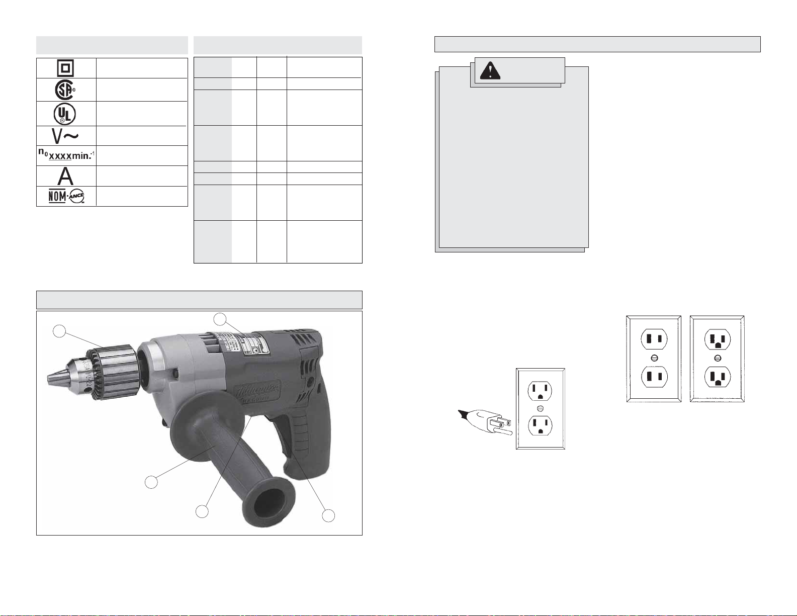
Symbology
Double Insulated
Canadian Standards
Association
Underwriters
Laboratories, Inc.
Volts Alternating
Current
No Load Revolutions
per Minute (RPM)
Amperes
Mexican Approvals
Marking
FUNCTIONAL DESCRIPTION
Specifications
Volts
Cat.
No.
0233-20
0234-1
0234-6
0235-21
0235-6
0236-6
0244-1
Right Angle Drive Unit Cat. No. 48-06-2871
2
AC
120
120
120
120
120
120
120
Amps
5.5
5.5
5.5
5.5
5.5
5.5
5.5
No Load
RPM
0-2800
without RAD 0-850
RAD low 0-565
RAD high 0-1275
without RAD 0-850
RAD low 0-565
RAD high 0-1275
0-850
0-850
without RAD 0-850
RAD low 0-565
RAD high 0-1275
without RAD 0-600
RAD low 0-400
RAD high 0-900
GROUNDING
WARNING!
Improperly connecting the
grounding wire can result in the
risk of electric shock. Check
with a qualified electrician if you
are in doubt as to whether the
outlet is properly grounded. Do
not modify the plug provided
with the tool. Never remove the
grounding prong from the plug.
Do not use the tool if the cord or
plug is damaged. If damaged,
have it repaired by a MILWAUKEE
service facility before use. If the
plug will not fit the outlet, have a
proper outlet installed by a
qualified electrician.
Grounded Tools:
Tools with Three Prong Plugs
Tools marked “Grounding Required” have
a three wire cord and three prong grounding plug. The plug must be connected to a
properly grounded outlet (See Figure A). If
the tool should electrically malfunction or
break down, grounding provides a low resistance path to carry electricity away from
the user, reducing the risk of electric shock.
The grounding prong in the plug is connected through the green wire inside the
cord to the grounding system in the tool.
The green wire in the cord must be the
only wire connected to the tool's grounding system and must never be attached to
an electrically “live” terminal.
Your tool must be plugged into an appropriate outlet, properly installed and
grounded in accordance with all codes and
ordinances. The plug and outlet should look
like those in Figure A.
Double Insulated Tools:
Tools with Two Prong Plugs
T ools marked “Double Insulated” do not require grounding. They have a special
double insulation system which satisfies
OSHA requirements and complies with the
applicable standards of Underwriters Laboratories, Inc., the Canadian Standard Association and the National Electrical Code.
Double Insulated tools may be used in either of the 120 volt outlets shown in
Figures B and C.
1. Chuck
2. Nameplate
3. Trigger
4. Forward/Reverse
switch
5. Side handle
Fig. B
Fig. C
Fig. A
5
4
3
54
Page 4
EXTENSION CORDS
TOOL ASSEMBLY
Grounded tools require a three wire extension cord. Double insulated tools can
use either a two or three wire extension
cord. As the distance from the supply outlet increases, you must use a heavier
gauge extension cord. Using extension
cords with inadequately sized wire causes
a serious drop in voltage, resulting in loss
of power and possible tool damage. Refer
to the table shown to determine the required minimum wire size.
The smaller the gauge number of the wire,
the greater the capacity of the cord. For
example, a 14 gauge cord can carry a
higher current than a 16 gauge cord. When
using more than one extension cord to make
up the total length, be sure each cord contains at least the minimum wire size required. If you are using one extension cord
for more than one tool, add the nameplate
amperes and use the sum to determine the
required minimum wire size.
Guidelines for Using Extension Cords
• If you are using an extension cord outdoors, be sure it is marked with the
suffix “W-A” (“W” in Canada) to indicate that it is acceptable for outdoor
use.
• Be sure your extension cord is properly wired and in good electrical
condition. Always replace a damaged
extension cord or have it repaired by a
qualified person before using it.
• Protect your extension cords from
sharp objects, excessive heat and
damp or wet areas.
Recommended Minimum Wire
Gauge for Extension Cords*
Nameplate
Amperes
0 - 2.0
2.1 - 3.4
3.5 - 5.0
5.1 - 7.0
7.1 - 12.0
12.1 - 16.0
16.1 - 20.0
* Based on limiting the line voltage drop to
five volts at 150% of the rated amperes.
Extension Cord Length
25'
18
18
18
18
16
14
12
READ AND SA VE ALL INSTRUCTIONS FOR FUTURE USE.
50'
18
18
18
16
14
12
10
75'
18
18
16
14
12
10
100'
18
16
14
12
10
150'
16
14
12
12
WARNING!
To reduce the risk of injury, always unplug tool before attaching
or removing accessories. Use
only specifically recommended
accessories. Others may be
hazardous.
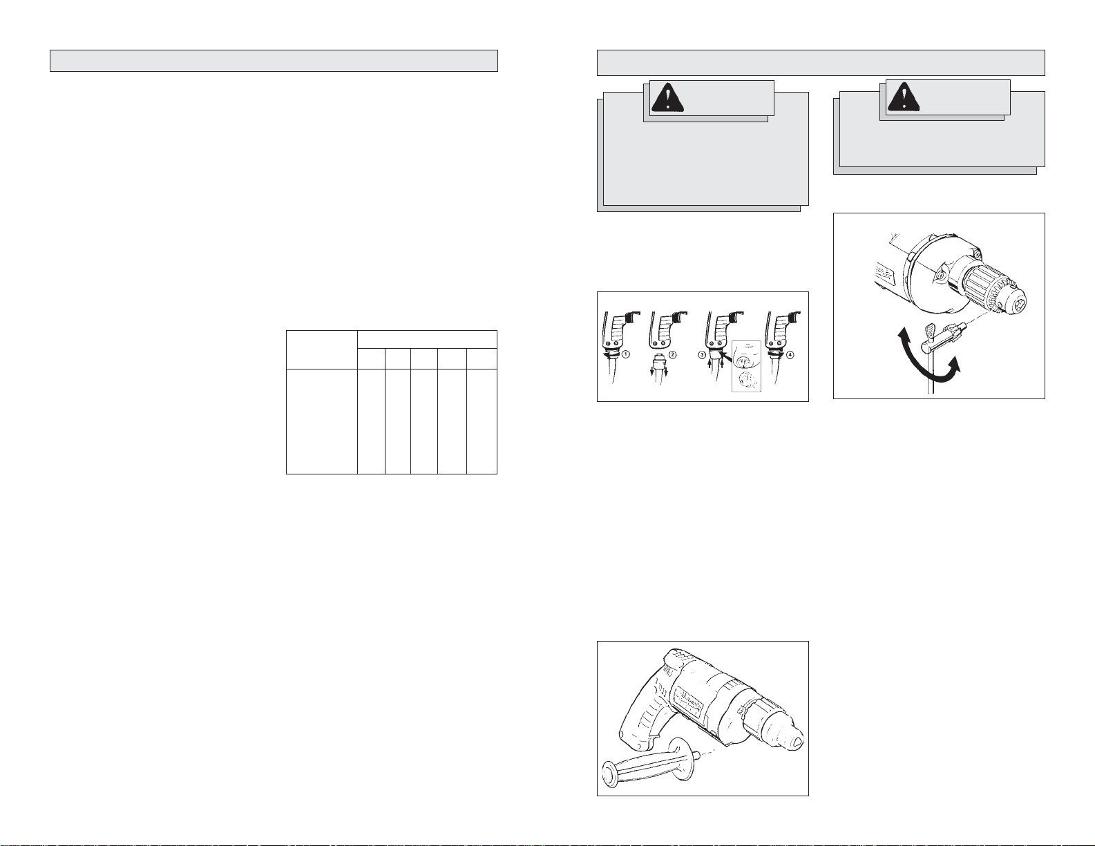
Removing and Replacing Quik-Lok
Cords (Fig. 1)
MILWAUKEE's exclusive Quik-Lok® Cords
provide instant field replacement or
substitution.
Fig. 1
1. T o remove the Quik-Lok® Cord, turn the
cord nut 1/4 turn to the left and pull it
out.
2. T o replace the Quik-Lok® Cord, align the
connector keyways and push the connector in as far as it will go. Turn the
cord nut 1/4 turn to the right to lock.
Installing Side Handle (Fig. 2)
MILWAUKEE Magnum Drills are supplied
with a side handle that can be installed on
either side of the tool for right or left handed
use. T o install the side handle, thread it into
the socket on the desired side of the tool
and tighten it securely. Always use the side
handle for best control.
Fig. 2
WARNING!
To prevent personal injury, always remove the chuck key from
the chuck after each use.
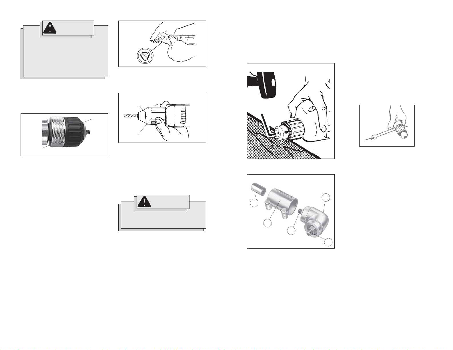
Installing Bits into Keyed Chucks (Fig. 3)
Cat. No. 0234-1, 0244-1
®
Fig. 3
Tighten
Loosen
1. Open the chuck jaws wide enough to
insert the bit. Be sure the bit shank and
chuck jaws are clean. Dirt particles may
prevent the bit from lining up
properly.
2. When using drill bits, insert the bit into
the chuck. Center the bit in the chuck
jaws and lift it about 1/16" off of the
bottom. Tighten the chuck jaws by hand
to align the bit.
When using screwdriver bits, insert the
bit far enough for the chuck jaws to
grip the bit shank. Tighten the chuck
jaws by hand to align the bit.
3. Place the chuck key in each of the three
holes in the chuck, turning it clockwise
as shown. Tighten securely.
4. To remove the bit, insert the chuck key
into one of the holes in the chuck and
turn it counterclockwise.
76
Page 5
WARNING!
To reduce the risk of injury:
• Do not grasp the bit while the
chuck is rotating or while the
bit is falling from the chuck.
• Release the trigger as soon as
the ratcheting stops to avoid
throwing the bit.
Installing Bits into Keyless Chucks
(Fig. 4) Cat. No. 0233-20
These tools are equipped with a handtightening keyless chuck. Always unplug
the tool before installing or removing bits.
Fig. 4
Sleeve
Fig. 5
3. T o close the chuck jaws, turn the chuck
sleeve in clockwise direction (Fig. 6).
Tighten securely. Several detents will
be felt as the chuck sleeve is turned.
Fig. 6
To close
Sleeve
the front of the tool). This should loosen
the chuck from the spindle which has a
right hand thread making it easy to remove
the chuck by hand.
NOTE: When replacing the chuck, always
replace the left hand thread screw in the
chuck.
Fig. 7
NOTE: Attaching the drill chuck to the
side marked “LOW” reduces the speed
by 1/3, or 33%. Attaching the drill chuck
to the opposite side increases the speed
by 50%.
3. When assembled, turn the Right Angle
Drive head to the desired position and
tighten the clamping screws to secure
the unit. Thread the chuck onto the
Right Angle Drive spindle (5). INSTALL
CHUCK LOCKING SCREW.
Removing the Chuck From Right
Angle Drive Unit (Fig. 9)
Fig. 9
Collar
1. T o open the chuck jaws, turn the sleeve
in the counterclockwise direction.
When using drill bits, allow the bit to
strike the bottom of the chuck. Center
the bit in the chuck jaws and lift it about
1/16" off of the bottom.
When using screwdriver bits, insert the
bit far enough for the chuck jaws to
grip the hex of the bit.
2. T o close the chuck jaws, hold the collar
while turning the sleeve in the clockwise direction. Tighten securely.
Installing Bits into Keyless Chucks
(Fig. 5 & 6) Cat. No. 0235-21
These tools are equipped with a spindlelock mechanism and a single-sleeve keyless chuck. Always unplug the tool before
inserting or removing bits.
1. T o open the chuck jaws, turn the chuck
sleeve in counterclockwise direction.
2. To install a bit, open the chuck jaws
slightly wider than the bit. Center the bit
in the chuck jaws and lift it about
1/16" off of the bottom. Align the bit as
shown (Fig. 5).
Cat. No. 0233-20
NOTE: If the spindle rotates when opening
or closing the chuck jaws, grasp the chuck
and slightly rotate back and forth to engage the spindle-lock mechanism.
The spindle will remain locked until the tool
is turned on. The spindle-lock mechanism
will automatically disengage when the tool
is turned on.
WARNING!
To reduce the risk of injury, always wear eye protection.
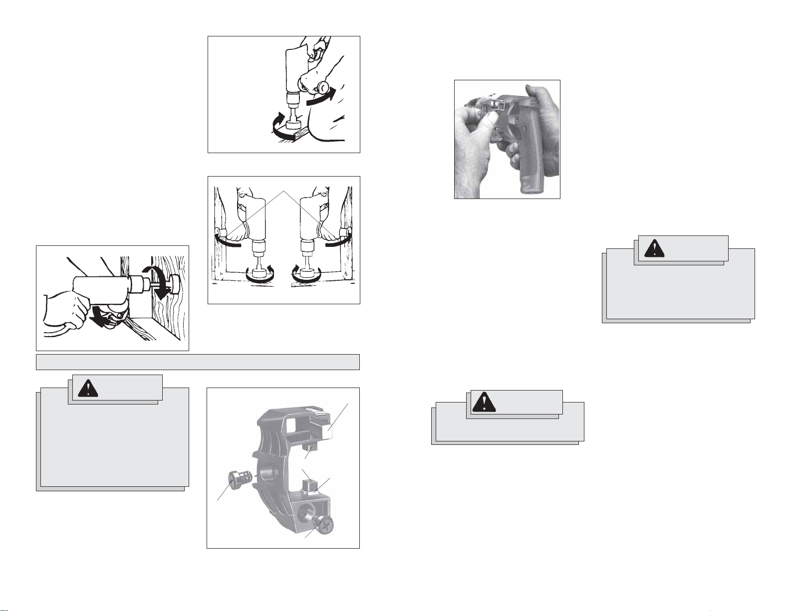
Chuck Removal (Fig. 7)
This tool is equipped with a threaded spindle
to hold the chuck. Before removing the
chuck, unplug the tool and open the chuck
jaws. A left-handed thread screw is located inside the chuck to prevent the chuck
from loosening when the tool is operated
in reverse direction. Remove the screw by
turning it clockwise. To remove the chuck,
hold the tool so that only the side of the
chuck rests firmly and squarely on a solid
workbench. Insert the chuck key or a chuck
remover bar in one of the keyholes. Turn
the chuck so the key is at about a 30° angle
to the bench top and strike the key sharply
with a hammer so the chuck turns in a
counterclockwise direction (looking from
Attaching Right Angle Drive to Drill
(Fig. 8)
Fig. 8
4
1
2
3
5
1. Remove the chuck from the drill following instructions (See “Removing the
Chuck From the Drill”). Slip the double
hex coupling (1) over the hex on the
drill spindle.
Loosen the clamping screws on the
clamping sleeve (2) and slip the sleeve
onto the drill collar.
2. Slide the Right Angle Drive head (4) into
the other side of the sleeve and turn
the drive head slightly in either direction so the hexagonal hole in the coupling (1) engages the hexagonal portion of the spindle (3).
The chuck can be removed from the Right
Angle Drive Unit in the same manner it is
removed from the drill; however, ALWAYS
REMOVE RIGHT ANGLE DRIVE FROM THE
DRILL BEFORE ATTEMPTING T O LOOSEN
THE CHUCK. This will prevent damaging
the drill's gearing. Use the open end wrench
provided to hold the Right Angle Drive
spindle before attempting to loosen the
chuck.
98
Page 6
OPERATION
APPLICATIONS
WARNING!
To reduce the risk of injury,
always wear eye protection.
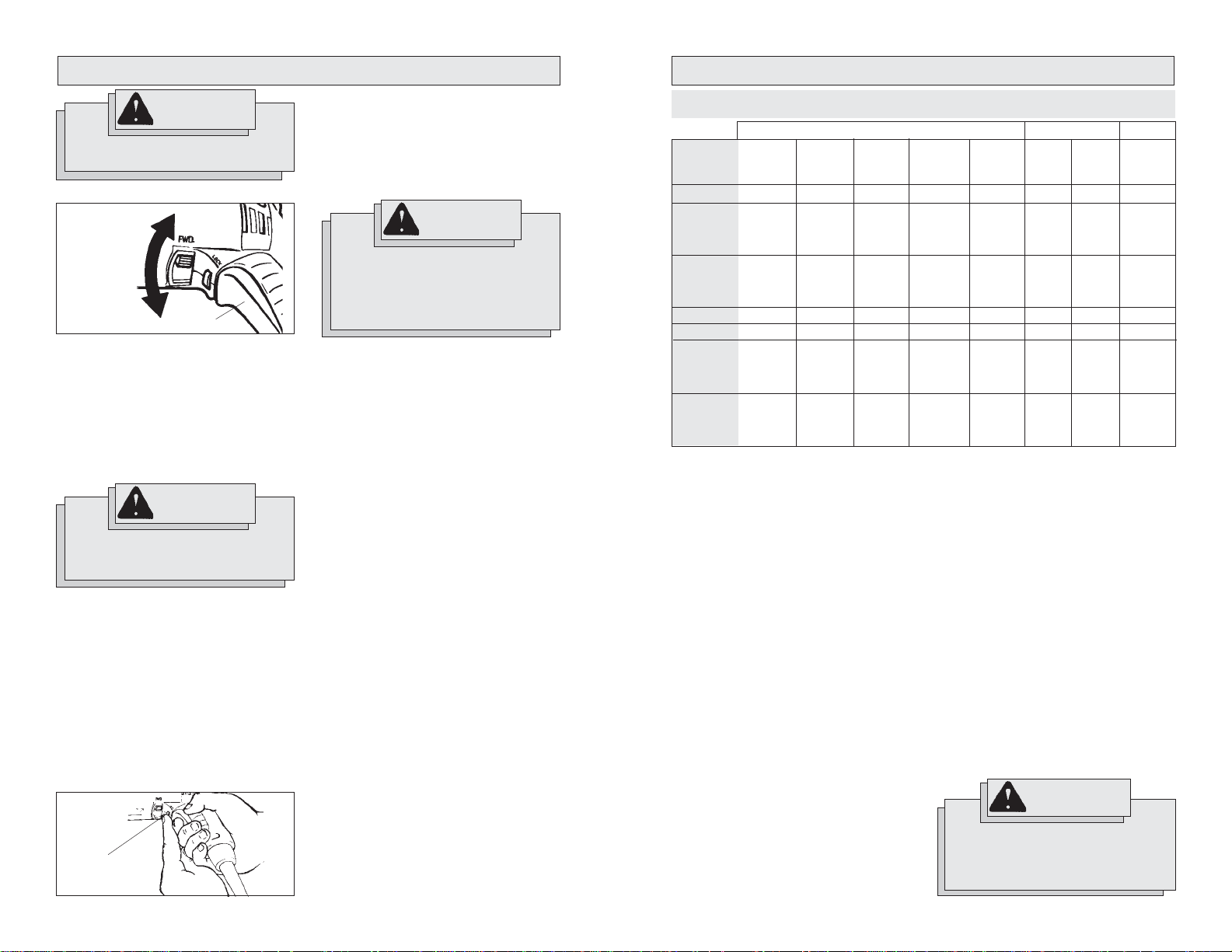
Using Forward/Reverse Switch (Fig. 10)
Fig. 10
1. For forward (clockwise) rotation, push
2. For reverse (counterclockwise) rota-
Forward
Reverse
Trigger
the forward/reverse switch to FWD as
shown.
tion, push the forward/reverse switch
to REV as shown. Although an interlock prevents reversing the tool while
the motor is running, allow it to come to
a full stop before reversing.
WARNING!
To reduce the risk of injury, keep
hands and cord away from the bit
and all moving parts.
Starting, Stopping and Controlling
Speed
1. To start the tool, pull the trigger.
2. To stop the tool, release the trigger.
3. To vary the drilling speed, simply increase or decrease pressure on the
trigger. The further the trigger is pulled,
the greater the speed.
Locking Trigger (Fig. 11)
The lock button holds the trigger in the ON
position for continuous full speed use.
Fig. 11
Lock
button
1. To lock the trigger, hold the lock button
in while pulling the trigger. Release the
trigger.
2. To unlock the trigger, pull the trigger
and release. The lock button will pop
out.
WARNING!
To reduce the risk of explosion,
electric shock and property
damage, always check the work
area for hidden pipes and wires
before drilling.
Drilling
1. Before drilling, be sure the workpiece
is clamped securely. Use backing material to prevent damage to the workpiece during breakthrough.
2. When starting a hole, place the drill bit
on the work surface and apply firm
pressure. Begin drilling at a slow speed,
gradually increasing the speed as you
drill.
3. Always apply pressure in line with the
bit. Use enough pressure to keep the
drill biting, but do not push hard enough
to stall the motor.
4. Reduce pressure and ease the bit
through the last part of the hole. While
the tool is still running, pull the bit out of
the hole to prevent jamming.
Stalling
If the tool seems as if it is about to stall,
maintain a firm grip and reduce pressure
slightly to allow the bit to regain speed. If
the tool does stall, release the trigger immediately. Reverse the motor, remove the
bit from the work and start again. Do not
pull the trigger on and off in an attempt to
start a stalled drill. This can damage the
drill.
CAPACITIES
Wood Steel Masonry
Cat.
No.
0233-20
0234-1
RAD low
RAD high
0234-6
RAD low
RAD high
0235-21
0235-6
0236-6
RAD low
RAD high
0244-1
RAD low
RAD high
NR = Not recommended
Selecting Bits
When selecting a bit, use the right type for
your job. For best performance, always
use sharp bits.
Drilling in Wood, Composition Materials and Plastic
When drilling in wood, composition materials and plastic, start the drill slowly, gradually increasing speed as you drill. When
using twist drill bits, pull the bit out of the
hole frequently to clear chips from the bit
flutes. Use low speeds for plastics with a
low melting point.
Drilling in Masonry
When drilling in masonry, use high speed
carbide-tipped bits. Drilling soft masonry
materials such as cinder block requires little
pressure. Hard materials like concrete require more pressure. A smooth, even flow
of dust indicates the proper drilling rate.
Do not let the bit spin in the hole without
cutting. Do not use water to settle dust or
to cool bit. Both actions will damage the
carbide.
Flat
Boring
Bits
1-1/2"
1-1/2"
1-1/2"
1-1/2"
1-1/2"
1-1/2"
1-1/2"
1-1/2"
1-1/2"
1-1/2"
1-1/2"
1-1/2"
1-1/2"
1-1/2"
Auger
Bits
1"
N R
1-1/2"
1-1/2"
1-1/8"
1-1/2"
1-1/2"
1-1/8"
1-1/2"
1-1/2"
1-1/2"
1-1/2"
1-1/8"
1-1/2"
1-1/2"
1-1/2"
Ship
Auger
Bits
N R
1-1/4"
1-1/2"
1"
1-1/4"
1-1/2"
1"
1-1/4"
1-1/4"
1-1/4"
1-1/2"
1"
1-1/2"
1-1/2"
1-1/4"
Selfeed
Bits
N R
2"
2-1/4"
1-1/2"
2"
2-1/4"
1-1/2"
2"
2"
2"
2-1/4"
1-1/2"
2-1/4"
2-9/16"
1-3/4"
Hole
Saws
1-3/4"
4-1/2"
2-3/4"
4-1/2"
2-3/4"
4-1/2"
2-3/4"
4-1/2"
3-1/4"
Drilling in Metal
When drilling in metal, use high speed steel
twist drills or hole saws. Use slow speeds
for hard metals and high speeds for softer
metals. Lubricate drill bits with cutting oil
when drilling in iron or steel. Use a coolant
when drilling in nonferrous metals such as
copper, brass or aluminum. Back the material to prevent binding and distortion on
breakthrough.
Driving Screws
When driving screws, use the proper
screwdriver bit for your job. After drilling
pilot and shank holes, start the screw
slowly and increase the speed as driving
progresses. Set the screw by slowing to
a stop. Do not run screws down at excessive speeds. To remove screws, reverse
the motor.
Twist
Drill
3/8"
4"
1/2"
1/2"
1/2"
4"
1/2"
1/2"
1/2"
4"
1/2"
4"
1/2"
4"
1/2"
1/2"
1/2"
1/2"
5"
1/2"
1/2"
Carbide-
Hole
Saws
1"
2"
2-1/8"
1-1/2"
2"
2-1/8"
1-1/2"
2"
2"
2"
2-1/8"
1-1/2"
2-1/4"
2-1/4"
1-3/4"
WARNING!
High rotational force. To reduce the
risk of injury, always hold or brace
secrely. Always use side handle on
tools rated 1200 RPM or less.
Tipped
Bits
3/8"
1/2"
9/16"
7/16"
1/2"
9/16"
7/16"
1/2"
1/2"
1/2"
9/16"
7/16"
9/16"
5/8"
1/2"
1110
Page 7
Bit Binding
A high rotational force occurs when a bit
binds. If the bit binds, the tool will be forced
in the opposite direction of the bit rotation
(See Fig. 12 - 14). Bits may bind if they are
misaligned or when they are breaking
through a hole. Wood boring bits can also
bind if they run into nails or knots. Be prepared for bit binding situations.
To reduce the chance of bit binding:
• Use sharp bits. Sharp bits are less likely
to bind when drilling.
• Use the proper bit for the job. There are
bits that are designed for specific purposes.
• Use caution when drilling pitchy, knotty,
wet or warped material or when drilling in material that may contain nails.
Typical Bracing Methods
Fig. 12
Reaction
Bracing against the floor
Forward rotation
MAINTENANCE
WARNING!
To reduce the risk of injury,
always unplug your tool before
performing any maintenance.
Never disassemble the tool or try
to do any rewiring on the tool's
electrical system. Contact a
MILWAUKEE service facility for
ALL repairs.
Replacing Brushes (Fig. 15 & 16)
MILWAUKEE Magnum Drills have an exclusive Brush Cartridge System. The tool
will not start when the brushes are worn
to 1/8", preventing expensive damage to
the armature. New brushes are provided
in the Cartridge for fast changes anywhere.
Fig. 13
Forward
rotation
Bracing against your leg
Fig. 14
Reverse rotation
Bracing against a stud
Fig. 15
Brush holder
screw
Replacement screw
Reaction
Forward rotation
Brushes
Reaction
Extra brushes
Brush
holder
1. Unplug tool and rest it on its side with
the cartridge facing up. Loosen the
brush holder screw in the cartridge and
pull cartridge out.
Fig. 16
2. Remove worn brushes. If the brushes
should fall into the tool, be sure to shake
them out before reinserting the cartridge. Discard BOTH brushes. Brushes
should always be replaced in sets.
3. A set of spare brushes is provided in
the cartridge. Remove the brushes from
storage compartment.
4. Position new brushes with the flat silver end facing into the brush holder.
Push cartridge into the tool and press
evenly on top and bottom of the cartridge to align terminals for proper connection.
5. Tighten the brush holder screw gently.
If the head of Screw is damaged, use
the replacement screw provided in the
cartridge.
WARNING!
Never use a metal screw as a
brush holder screw.
Maintaining Tools
Keep your tool in good repair by adopting a
regular maintenance program. Before use,
examine the general condition of your tool.
Inspect guards, switches, tool cord set and
extension cord for damage. Check for
loose screws, misalignment, binding of
moving parts, improper mounting, broken
parts and any other condition that may affect its safe operation. If abnormal noise
or vibration occurs, turn the tool off immediately and have the problem corrected
before further use. Do not use a damaged
tool. T ag damaged tools “DO NOT USE” until
repaired (see “Repairs”).
Under normal conditions, relubrication is
not necessary until the motor brushes
need to be replaced. After six months to
one year, depending on use, return your
tool to the nearest MILWAUKEE service
facility for the following:
• Lubrication
• Brush inspection and replacement
• Mechanical inspection and cleaning
(gears, spindles, bearings, housing,
etc.)
• Electrical inspection (switch, cord,
armature, etc.)
• Testing to assure proper mechanical
and electrical operation
WARNING!
To reduce the risk of injury,
electric shock and damage to the
tool, never immerse your tool in
liquid or allow a liquid to flow
inside the tool.
Cleaning
Clean dust and debris from vents. Keep
the tool handles clean, dry and free of oil
or grease. Use only mild soap and a damp
cloth to clean your tool since certain cleaning agents and solvents are harmful to plastics and other insulated parts. Some of
these include: gasoline, turpentine, lacquer
thinner, paint thinner, chlorinated cleaning
solvents, ammonia and household detergents containing ammonia. Never use flammable or combustible solvents around
tools.
Repairs
If your tool is damaged, return the entire
tool to the nearest service center.
1312
Page 8

ACCESSORIES
WARNING!
To reduce the risk of injury,
always unplug the tool before
attaching or removing
accessories. Use only specifically
recommended accessories.
Others may be hazardous.
For a complete listing of accessories refer
to your MILWAUKEE Electric Tool catalog
or go on-line to www.milwaukeetool.com.
To obtain a catalog, contact your local distributor or a service center.
FIVE YEAR TOOL
LIMITED WARRANTY
Every MILWAUKEE tool is tested before
leaving the factory and is warranted to be
free from defects in material and workmanship. MILWAUKEE will repair or replace (at MILWAUKEE’s discretion), without charge, any tool (including battery
chargers) which examination proves to be
defective in material or workmanship from
five (5) years after the date of purchase.
Return the tool and a copy of the purchase
receipt or other proof of purchase to a
MILWAUKEE Factory Service/Sales Support Branch location or MILWAUKEE Au-
thorized Service Station, freight prepaid
and insured. This warranty does not cover
damage from repairs made or attempted
by other than MILWAUKEE authorized personnel, abuse, normal wear and tear, lack
of maintenance, or accidents.
Battery Packs, Flashlights, and Radios are
warranted for one (1) year from the date
of purchase.
THE REP AIR AND REPLACEMENT REMEDIES
DESCRIBED HEREIN ARE EXCLUSIVE. IN NO
EVENT SHALL MILWAUKEE BE LIABLE
FOR ANY INCIDENT AL, SPECIAL, OR CONSEQUENTIAL DAMAGES, INCLUDING LOSS
OF PROFITS.
THIS WARRANTY IS EXCLUSIVE AND IN
LIEU OF ALL OTHER WARRANTIES, OR
CONDITIONS, WRITTEN OR ORAL, EXPRESSED OR IMPLIED FOR
MERCHANTABLILITY OR FITNESS FOR
PAR TICULAR USE OR PURPOSE.
This warranty gives you specific legal
rights. You may also have other rights that
vary from state to state and province to
province. In those states that do not allow
the exclusion of implied warranties or limitation of incidental or consequential damages, the above limitations or exclusions
may not apply to you. This warranty applies to the United States, Canada, and
Mexico only.
RÈGLES GÉNÉRALES DE SÉCURITÉ POUR LES OUTILS
ÉLECTRIQUE
AVERTISSEMENT!
LIRE SOIGNEUSEMENT TOUTES LES INSTRUCTIONS
Le non respect des instructions ci-après peut entraîner des chocs
électriques, des incendies et/ou des blessures graves. Le terme «outil
électrique» figurant dans les avertissements ci-dessous renvoie à l’outil
électrique à alimentation par le réseau (à cordon) ou par batterie (sans fil).
CONSERVER CES INSTRUCTIONS
SÉCURITÉ DU LIEU
DE TRAVAIL
1. Maintenir la zone de travail propre
et bien éclairée. Les zones
encombrées ou mal éclairées sont
favorables aux accidents.
2. Ne pas utiliser d’outil électrique
dans une atmosphère explosive,
telle qu’en en présence de
liquides, de gaz ou de poussières
inflammables. Les outils électriques
génèrent des étincelles qui peuvent
enflammer les poussières ou les
fumées.
3. Tenir les enfants et les personnes
non autorisées à l’écart pendant
le fonctionnement d’un outil
électrique. Un manque d’attention de
l’opérateur risque de lui faire perdre le
contrôle de l’outil.
SÉCURITÉ ÉLECTRIQUE
4. La fiche de l’outil électrique doit
correspondre à la prise
d’alimentation. Ne jamais modifier
la fiche d’une manière
quelconque. Ne pas utiliser
d’adaptateur avec les outils
électriques mis à la terre (à la
masse). Des fiches non modifiées et
des prises d’alimentation assorties
réduisent le risque de choc électrique.
5. Éviter tout contact corporel avec
des surfaces reliées à la masse
ou à la terre telles que tuyaux,
radiateurs, cuisinières et
réfrigérateurs. Un risque de choc
électrique plus élevé existe si le corps
est relié à la masse ou à la terre.
6. Ne pas exposer les outils
électriques à la pluie ou à
l’humidité. Le risque de choc
électrique augmente si de l’eau s’infiltre
dans un outil électrique.
7. Prendre soin du cordon. Ne jamais
utiliser le cordon pour transporter,
tirer ou débrancher l’outil
électrique. Tenir le cordon à l’écart
de la chaleur, des huiles, des
arêtes coupantes ou des pièces
en mouvement. Un cordon
endommagé ou emmêlé présente un risque accru de choc électrique.
8. Se procurer un cordon
d’alimentation approprié en cas
d’utilisation d’un outil électrique à
l’extérieur. L’utilisation d’un cordon
d’alimentation pour usage extérieur
réduit le risque de choc électrique.
SÉCURITÉ INDIVIDUELLE
9. Être sur ses gardes, être attentif
et faire preuve de bon sens en
utilisant un outil électrique. Ne pas
utiliser un outil électrique en cas
de fatigue ou sous l’influence de
drogues, d’alcool ou de
médicaments. Un instant d’inattention
lors de l’utilisation d’un outil électrique
peut entraîner des blessures graves.
10. Utiliser un équipement de
sécurité. Toujours porter des lunettes de protection. Un équipement
de sécurité comprenant masque antipoussière, chaussures de sécurité antidérapantes, casque ou dispositif de
protection anti-bruit peut, dans les
circonstances appropriées, réduire le
risque de blessure.
1514
Page 9

11. Éviter tout démarrage accidentel
de l’outil. S’assurer que le
commutateur est en position OFF
(Arrêt) avant de brancher l’outil.
Le port de l’outil avec un doigt sur le
commutateur ou son branchement avec
le commutateur en position ON (Marche)
sont favorables aux accidents.
12. Retirer toute clé de réglage avant
de mettre l’outil sous tension. Une
clé laissée attachée sur une pièce mobile de l’outil électrique peut entraîner
des blessures.
13. Ne pas travailler à bout de bras.
Bien garder un bon équilibre à tout
instant. Ceci permet de mieux
préserver la maîtrise de l’outil électrique
dans des situations imprévues.
14. Porter des vêtements adéquats.
Ne pas porter de vêtements
amples ni de bijoux. Ne pas
approcher les cheveux,
vêtements et gants des pièces en
mouvement. Les vêtements amples,
les bijoux ou les cheveux longs risquent
d’être happés par les pièces en
mouvement.
15. Si des dispositifs sont prévus
pour l’extraction et la récupération
des poussières, vérifier qu’ils
sont connectés et utilisés
correctement. L’utilisation de ces
dispositifs peut réduire les risques liés
aux poussières.
UTILISATION ET ENTRETIEN
DE L’OUTIL ÉLECTRIQUE
16. Ne pas forcer l’outil électrique.
Utiliser l’outil électrique approprié
à l’application considérée. L’outil
électrique adapté au projet considéré
produira de meilleurs résultats, dans
des conditions de sécurité meilleures,
à la vitesse pour laquelle il a été conçu.
17. Ne pas utiliser l’outil électrique si
le commutateur ne le met pas
sous ou hors tension. Tout outil
électrique dont le commutateur de
marche-arrêt est inopérant est
dangereux et doit être réparé.
18. Débrancher la fiche de la prise
d’alimentation et/ou la batterie de
l’outil électrique avant d’effectuer
des réglages, de changer
d’accessoires ou de ranger l’outil.
De telles mesures de sécurité
préventive réduisent le risque de mettre
l’outil en marche accidentellement.
19. Ranger les outils électriques
inutilisés hors de la portée des
enfants et ne pas laisser des
personnes qui connaissent mal
les outils électriques ou ces instructions utiliser ces outils. Les
outils électriques sont dangereux dans
les mains d’utilisateurs non formés à
leur usage.
20. Entretien des outils électriques.
S’assurer de l’absence de tout
désalignement ou de grippage
des pièces mobiles, de toute rupture de pièce ou de toute autre
condition qui pourrait affecter le
bon fonctionnement de l’outil
électrique. En cas de dommages,
faire réparer l’outil avant de
l’utiliser de nouveau. Les outils
électriques mal entretenus sont à la
source de nombreux accidents.
21. Garder les outils de coupe affûtés
et propres. Les outils de coupe
correctement entretenus et bien affûtés
risquent moins de se gripper et sont
plus faciles à manier.
22. Utiliser cet outil électrique, les
accessoires, les mèches, etc.
conformément à ces instructions
et de la façon prévue pour ce type
particulier d’outil électrique, tout
en prenant en compte les conditions de travail et le type de projet
considérés. L’utilisation de cet outil
électrique pour un usage autre que
l’usage prévu peut créer des situations
dangereuses.
ENTRETIEN
23. Faire effectuer l’entretien de l’outil
électrique par un technicien
qualifié qui n’utilisera que des
pièces de rechange identiques. La
sécurité d’utilisation de l’outil en sera
préservée.
RÈGLES DE SÉCURITÉ PARTICULIÈRE
1. Tenir l’outil par les surfaces de prise isolées si, au cours des travaux, l’outil
de coupe risque d’entrer en contact avec des fils cachés ou avec son propre
cordon. Le contact avec un fil sous tension met les parties métalliques exposées de
l’outil sous tension, ce qui infligera un choc électrique à l’opérateur.
2. Utiliser les poignées auxiliaires fournies avec l’outil. Une perte de contrôle peut
provoquer des blessures.
3. Porter des protège-oreilles avec un marteau perforateur. Une exposition au
bruit peut provoquer une perte auditive.
4. Entretenez les étiquettes et marqies di fabricant. Les indications qu'elles
contiennent sont précieuses. Si elles deviennent illisibles ou se détachent, faites-les
remplacer gratuitement à un centre de service MILWAUKEE accrédité.
5. AVERTISSEMENT! La poussière degage par perçage, sclage, perçage et autres travaux
de construction contient des substances chimiques reconnues comme pouvant causer
le cancer, des malformations congénitales ou d’autres troubles de reproduction. Voici
quelques exemples de telles substances :
• Le plomb contenu dans la peinture au plomb.
• Le silice cristallin contenu dans la brique, le béton et divers produits de maçonnerie.
• L’arsenic et le chrome servant au traitement chimique du bois.
Les risque associés à l’exposition à ces substances varient, dépendant de la fréquence
des travaux. Afin de minimiser l’exposition à ces substances chimiques, assurez-vous
de travailler dans un endroit bien aéré et d’utiliser de l’equipement de sécurité tel un
masque antipoussière spécifiquement conçu pour la filtration de particules
microscopiques.
1716
Page 10

Pictographie
Double Isolation
l’Association canadienne
de normalisation
Underwriters
Laboratories Inc.
Courant alternatif seul.
T/Min. á vide (RPM)
Ampères
Inscription mexicaine
d’approbation
DESCRIPTION FONCTIONNELLE
Spécifications
No de
Volts
120
120
120
120
120
120
120
2
A
5,5
5,5
5,5
5,5
5,5
5,5
5,5
cat.
0233-20
0234-1
0234-6
0235-21
0235-6
0236-6
0244-1
l'unité coudée 48-06-2871
1
T-min. à vide
0 - 2 800
sans l'unité coudée 0-850
l'unité coudée bas 0-565
l'unité coudée haut 0-1 275
sans l'unité coudée 0-850
l'unité coudée bas 0-565
l'unité coudée haut 0-1 275
0-850
0-850
sans l'unité coudée 0-850
l'unité coudée bas 0-565
l'unité coudée haut 0-1 275
sans l'unité coudée 0-600
l'unité coudée bas 0-400
l'unité coudée haut 0-900
AVERTISSEMENT!
Si le fil de mise à la terre est
incorrectement raccordé, il peut
en résulter des risques de choc
électrique. Si vous n’êtes pas
certain que la prise dont vous
vous servez est correctement
mise à la terre, faites-la vérifier
par un électricien. N’altérez pas la
fiche du cordon de l’outil.
N’enlevez pas de la fiche, la dent
qui sert à la mise à la terre.
N’employez pas l’outil si le cordon
ou la fiche sont en mauvais état.
Si tel est le cas, faites-les
réparer dans un centre-service
MILWAUKEE accrédité avant de
vous en servir. Si la fiche du cordon ne s’adapte pas à la prise,
faites remplacer la prise par un
électricien.
Outils mis à la terre :
Outils pourvus d’une fiche de cordon
à trois dents
Les outils marqués « Mise à la terre requise
» sont pourvus d’un cordon à trois fils dont
la fiche a trois dents. La fiche du cordon
doit être branchée sur une prise
correctement mise à la terre (voir Figure A).
De cette façon, si une défectuosité dans
le circuit électrique de l’outil survient, le
relais à la terre fournira un conducteur à
faible résistance pour décharger le courant et protéger l’utilisateur contre les
risques de choc électrique.
MISE A LA TERRE
La dent de mise à la terre de la fiche est
reliée au système de mise à la terre de
l’outil via le fil vert du cordon. Le fil vert du
cordon doit être le seul fil raccordé à un
bout au système de mise à la terre de l’outil
et son autre extrémité ne doit jamais être
raccordée à une borne sous tension
électrique.
Votre outil doit être branché sur une prise
appropriée, correctement installée et mise
à la terre conformément aux codes et
ordonnances en vigueur. La fiche du cordon et la prise de courant doivent être
semblables à celles de la Figure A.
Outils à double isolation :
Outils pourvus d’une fiche de cordon
à deux dents
Les outils marqués « Double Isolation » n’ont
pas besoin d’être raccordés à la terre. Ils
sont pourvus d’une double isolation
conforme eux exigences de l’OSHA et
satisfont aux normes de l’Underwriters
Laboratories, Inc., de l’Association
canadienne de normalisation (ACNOR) et
du « National Electrical Code » (code national de l’électricité). Les outils à double
isolation peuvent être branchés sur
n’importe laquelle des prises à 120 volt
illustrées ci-contre Figure B et C.
1. Mandrin
2. Fiche signalétique
3. Détente
4. L'inverseur de rotation
5. Poignée latérale
Fig. B
5
4
Fig. C
Fig. A
3
1918
Page 11

CORDONS DE RALLONGE
Si l’emploi d’un cordon de rallonge est
nécessaire, un cordon à trois fils doit être
employé pour les outils mis à la terre. Pour
les outils à double isolation, on peut employer indifféremment un cordon de
rallonge à deux ou trois fils. Plus la longueur
du cordron entre l’outil et la prise de courant est grande, plus le calibre du cordon
doit être élevé. L’utilisation d’un cordon de
rallonge incorrectement calibré entraîne
une chute de voltage résultant en une perte
de puissance qui risque de détériorer l’outil.
Reportez-vous au tableau ci-contre pour
déterminer le calibre minimum du cordon.
Moins le calibre du fil est élevé, plus sa
conductivité est bonne. Par exemple, un
cordon de calibre 14 a une meilleure
conductivité qu’un cordon de calibre 16.
Lorsque vous utilisez plus d’une rallonge
pour couvrir la distance, assurez-vous que
chaque cordon possède le calibre minimum
requis. Si vous utilisez un seul cordon pour
brancher plusieurs outils, additionnez le
chiffre d’intensité (ampères) inscrit sur la
fiche signalétique de chaque outil pour
obtenir le calibre minimal requis pour le
cordon.
Directives pour l’emploi des cordons
de rallonge
• Si vous utilisez une rallonge à
l’extérieur, assurez-vous qu’elle est
marquée des sigles « W-A » (« W » au
Canada) indiquant qu’elle est adéquate
pour usage extérieur.
• Assurez-vous que le cordon de
rallonge est correctement câblé et en
bonne condition. Remplacez tout cordon derallonge détérioré ou faites-le
remettre en état par une personne
compétente avant de vous en servir.
• T enez votre cordon de rallonge à l’écart
des objets ranchants, des sources de
grande chaleur et des endroits humides
ou mouillés.
Calibres minimaux recommandés
pour les cordons de rallonge*
Fiche
signalétique
Ampères
0 - 5,0
5,1 - 8,0
8,1 - 12,0
12,1 - 15,0
15,1 - 20,0
* Basé sur sur une chute de voltage limite
de 5 volts à 150% de l’intensité moyenne
de courant.
Longueur du cordon de
rallonge (m)
30,4
15,2
16
16
14
12
10
22,8
16
14
12
10
10
14
12
10
10
--
7,6
16
16
14
12
10
45,7
LISEZ A TTENTIVEMENT CES INSTRUCTIONS ET CONSERVEZ-LES
POUR LES CONSUL TER AU BESOIN.
12
10
MONTAGE DE L'OUTIL
AVERTISSEMENT!
Afin de minimiser les risques de
blessures, débranchez toujours
l’outil avant d’y installer des
accessoires ou d’en enlever.
L’usage d’accessoires autres
que ceux qui sont expressément
recommandés peut comporter
des risques.
Retrait et remplacement du cordon
Quik-Lok® (Fig. 1)
Les cordons Quik-Lok® exclusifs à
MILWAUKEE permettent d’installer le cordon ou de le remplacer sur place en un
tournemain.
Fig. 1
60,9
12
--
--
--
--
--
--
--
1. Pour retirer le cordon Quik-Lok®, tournez
l’écrou du cordon 1/4 de tour vers la
gauche et retirez-le.
2. Pour remettre le cordon en place,
alignez les rainures à clavettes du
connecteur et poussez le connecteur
aussi loin que possible. T ournez ensuite
l’écrou du cordon 1/4 de tour vers la
droite pour le verrouiller.
Installation de la poignée latérale (Fig. 2)
Les perceuses MILWAUKEE Magnum sont
pourvues d’une poignée latérale qui peut
être installée sur l’un ou l’autre des côtés
de l’outil pour usage gaucher ou droitier.
Pour installer la poignée latérale, vissez-la
à fond dans l’orifice fileté sur le côté désiré.
Servez-vous toujours de la poignée
latérale pour obtenir une meilleure maîtrise
de l’outil.
Fig. 2
AVERTISSEMENT!
Pour prévenir les blessures
corporelles, retirez toujours la clé
du mandrin après chaque usage.
Pose des mèches dans le mandrin
à clé (Fig. 3) No de Cat. 0234-1, 0244-1
Fig. 3
Serrez
Desserrez
1. Écartez les mâchoires du mandrin,
assez pour y insérer la mèche.
Assurez-vous que la queue de la
mèche et les mâchoires du mandrin sont
propres car la saleté pourrait nuire à
un alignement correct de la mèche.
2. Lorsque vous utilisez une mèche pour
percer, insérez-la dans le mandrin.
Centrez-la entre les mâchoires et
retirez-la d’environ 1,6 mm (1/16") du
fond du mandrin. Serrez les mâchoires
à la main pour aligner la mèche.
Si vous servez de la perceuse comme
tournevis, insérez la lame-tournevis
assez loin pour que les mâchoires du
mandrin en agrippent parfaitement la
tige. Serrez les mâchoires du mandrin
à la main pour aligner la pièce.
2120
Page 12

3. Placez la clé de mandrin dans chacun
des trois trous du mandrin, tournez-la
en sens horaire, tel qu’indiqué, et
serrez-la à fond.
4. Pour retirer la lame, insérez la clé de
mandrin dans l’un des trous du mandrin
et tournez-la en sens inverse-horaire.
AVERTISSEMENT!
Pour réduire les risques de
blessures:
• N'empoignez pas la mèche
pendant que le mandrin est
en mouvement ou pendant
que la mèche est éjectée du
mandrin.
• Relâchez la détente dès que
le mécansime à rochet
s'arrête, afin d'éviter
Pose des mèches dans le mandrin
sans clé (Fig. 4) No de Cat. 0233-20
Les outils sont pourvus d'un mandrin sans
clé à serrage manuel. Débranchez toujours
l'outil avant d'installer ou d'enlever les
mèches.
Fig. 4
Collet
1. Pour écarter les mâchoires du mandrin,
tournez la douille en sens inversehoraire.
Si vous insérez une mèche pour percer,
laissez la mèche atteindre le fond du
mandrin. Centrez-la entre les mâchoires
du mandrin et retirez-la d'environ 1,6
mm (1/16") du fond.
Si vous insérez une pièce tourne-vis,
poussez-la assez loin dans le mandrin
pour que les mâchoires en agrippent la
tige hex.
2. Pour refermer les mâchoires du mandrin, tenez le collet en faisant tourner la
douille en sens horaire. Serrez à fond.
No de Cat. 0233-02
Douille
Pose des mèches dans le mandrin à
manchon simple et serrage sans clé
No de Cat. 0235-21 (Fig. 5 & 6)
Les outils sont pourvus d’un mandrin à
manchon simple et d'un mécanisme
d’encliquetage sans clé. Débranchez
toujours l’outil avant d’y installer ou d’en
retirer un foret.
1. Pour écarter les mâchoires du mandrin,
tournez le manchon du mandrin en sens
inverse-horaire.
2. Pour installer un foret, écartez les
mâchoires du mandrin pour introduirelr
foret. Centrez le foret entre les
mâchoires et retirez-le d’environ
1,6 mm (1/16"). du fond du mandrin.
Alignez le foret tel qu' indiqué à la
figure 5.
Fig. 5
3. Pour refermer les mâchoires, faites
tourner le manchon du mandrin en sens
horaire, et serrez-le à fond (Fig. 6). En
serrant le manchon, vous percevrez
plusieurs encliquetages.
Fig. 6
N.B. Si l’arbre tourne avec le manchon,
empoignez le mandrin et faites-le tourner
légèrement d’un côté et de l’autre pour
engager le mécanisme d’encliquetage.
L’arbre demeurera verrouillé jusqu’à ce que
l’outil soit mis en marche. Le mécanisme
d’encliquetage se déclenchera de lui-même
lorsque l’outil sera mis en marche.
Pour fermer
Douille
AVERTISSEMENT!
Pour minimiser les risques de
blessures au yeux, portez
toujours des lunettes à coques
latérales.
Retrait du mandrin (Fig. 7)
Cet outil est pourvu d'un pivot fileté sur
lequel est vissé le mandrin. Avant de retirer
le mandrin, débranchez l'outil et écartez
les mâchoires du mandrin. Une vis à pas
gauche est posée à l'intérieur du mandrin
pour l' empêcher de se relâcher lorsque la
rotation est inversée. Enlevez la vis en la
tournent en sens horaire. Pour retirer le
mandrin, tenz l'outil de façon à ce que suel
mandrin repose solidement sur l'etabli.
Sérrez une clé hex en le mandrin. Tournez
le mandrin pour que la clé soit à un angle
d'environ 30° de la surface de l'etabli et
donnez un coup sec à la clé avec un
marteau pour faire tourner le mandrin en
sens inverse-horaire (vu du devant de
l'outil). Cette technique derait desserrer le
mandrin de pivot à filetage droitier et faciliter
le retrait du mandrin avec la main.
N.B. Lorsque vous remontez le mandrin,
n'oubliez pas de poser la vis à pas gauche
dans le mandrin.
Fig. 7
Fixation de l'unité coudée à la
perceuse (Fig. 8)
1. Retirez le mandrin de la perceuse selon
les instructions intitulées « Retrait du
mandrin de la perceuse ». Glissez le
manchon polygonal (1) sur la partie
hexagonale du pivot de la perceuse.
Dévissez les vis de fixation sur la douille
de fixation (2) et glissez la douille sur le
collet de la perceuse.
2. Passez la tête coudée (4) sur l'autre
bout de la douille et tournez-la
légèrement dans les deux sens pour
que le trou hexagonal du manchon (1)
s'engage sur la partie hexagonale du
pivot (3).
N.B. La pose du mandrin sur le côté
marqué « LOW » réduira la vitesse de
rotation du tiers ou 33%. La fixation du
mandrin au pivot opposé augmente la
vitesse de rotation de 50%.
3. Après avoir monté la tête coudée,
tournez-la à la position désirée et serrez
les vis de fixation pout la maintenir en
place. Vissez le mandrin sur le pivot de
la tête coudée (5). POSEZ LA VIS DE
VERROUILLAGE DU MANDRIN.
Fig. 8
4
1
2
3
5
Retrait du mandrin de l'unité coudée
(Fig. 9)
Le mandrin peut être retiré de l'unité coudée
de la même façon qu'il se retire de la
perceuse, cependant, RETIREZ TOUJOURS
L'UNITÉ COUDÉE DE LA PERCEUSE A VANT
D'ESSAYER DE DÉVISSER LE MANDRIN.
Ceci, pout prévenir les dommages aux
engrenages de la perceuse. Utilisez la clé
à fourche fournie avec l'outil pour bloquer
le pivot de l'unité coudée, avant d'essayer
de dévisser le mandrin.
Fig. 9
MANIEMENT
AVERTISSEMENT!
Pour minimiser les risques de
blessures au yeux, portez
toujours de lunettes à coque
latérales.
2322
Page 13

Utilisation de l’inverseur de rotation
(Fig. 10)
Fig. 10
Avant
Inverse
Détente
1. Pour la rotation avant, (sens horaire)
poussez le levier inverseur vers la
marque « FWD », tel qu’indiqué.
2. Pour inverser la rotation (sens inversehoraire), poussez le levier inverseur vers
la marque « REV », tel qu’indiqué. Malgré
qu’un système de verrouillage
réciproque empêche l’inversion de la
rotation pendant que l’outil est en
marche, laissez quand même l’outil
s’arrêter complètement de tourner avant
d’actionner le levier inverseur.
AVERTISSEMENT!
Pour minimiser les risques de
blessures, gardez les mains et le
cordon à distance de la mèche et
des pièces en mouvement.
Démarrage, arrêt et contrôle de vitesse
1. Pour mettre l’outil en marche, appuyez
sur la détente.
2. Pour arrêter l’outil, relâchez la détente.
3. Pour varier la vitesse de rotation, il suffit
simplement d’augmenter ou de diminuer
la pression sur la détente. Plus la détente
est enfoncée, plus la vitesse est grande.
Verrouillage de la détente (Fig. 11)
Le bouton de verrouillage placé à côté de la
détente sert à maintenir la détente en position de marche « ON » pour la rotation
interrompue à plein régime.
Fig. 11
Bouton de
verrouillage
1. Pour verrouiller la détente, enfoncez
le bouton de verrouillage tout en
appuyant sur la détente. Relâchez la
détente.
2. Pour déverrouiller la détente,
enfoncez et relâchez la détente.
AVERTISSEMENT!
Pour minimiser les risques
d’explosion, choc électrique, et
dommage à la propriété,
inspectez l’aire de travail pour en
déceler les tuyaux et les câbles
électriques avant perçage.
Perçage
1. Avant de driller, assurez-vous que le
matériau est fixé solidement. Appuyezle sur une pièce rigide pour éviter de
l’endommager en passant au travers.
2. Pour commencer à percer un trou,
placez le foret sur la surface à travailler
et appuyez fermement sur l’outil.
Commencez à driller lentement pour
ensuite augmenter la vitesse de
perçage.
3. Appliquez toujours la pression en droite
ligne avec le foret. Appuyez assez
fermement pour qu’il morde dans la
pièce sans toutefois causer l’arrêt du
moteur.
4. Réduisez la pression et relâchez la rotation en arrivant à la phase finale du
perçage. Pour éviter le blocage, retirez
le foret du trou tandis que l’outil tourne
encore.
Blocage
Si l’outil semble vouloir se coincer, maintenez-le
solidement et réduisez légèrement la pression
afin que le moteur puisse reprendre de la vitesse.
Si l’outil reste coincé, relâchez immédiatement
la détente. Inversez la rotation et retirez le foret
de la pièce à travailler avant de recommencer le
perçage. Il est inutile d’essayer de remettre l’outil
en marche lorsqu’il est coincé. Des tentatives
intermittentes de remise en marche pourraient
endommager la perceuse.
APPLICATIONS
Capacities
Bois
à
bois
N R
Méches
à
bateau
N R
32 mm
(1-1/4")
38 mm
(1-1/2")
25 mm
(1")
32 mm
(1-1/4")
38 mm
(1-1/2")
25 mm
(1")
32 mm
(1-1/4")
32 mm
(1-1/4")
32 mm
(1-1/4")
38 mm
(1-1/2")
25 mm
(1")
38 mm
(1-1/2")
38 mm
(1-1/2")
32 mm
(1-1/4")
Méches d'
No.
de cat.
0233-20
0234-1
l'unité
coudée bas
l'unité
coudée haut
0234-6
l'unité
coudée bas
l'unité
coudée haut
0235-21
0235-6
0236-6
l'unité
coudée bas
l'unité
coudée haut
0244-1
l'unité
coudée bas
l'unité
coudée haut
alésage
25 mm
(1")
38 mm
(1-1/2")
38 mm
(1-1/2")
38 mm
(1-1/2")
38 mm
(1-1/2")
38 mm
(1-1/2")
38 mm
(1-1/2")
38 mm
(1-1/2")
38 mm
(1-1/2")
38 mm
(1-1/2")
38 mm
(1-1/2")
38 mm
(1-1/2")
38 mm
(1-1/2")
38 mm
(1-1/2")
38 mm
(1-1/2")
38 mm
(1-1/2")
38 mm
(1-1/2")
29 mm
(1-1/8")
38 mm
(1-1/2")
38 mm
(1-1/2")
29 mm
(1-1/8")
38 mm
(1-1/2")
38 mm
(1-1/2")
38 mm
(1-1/2")
38 mm
(1-1/2")
29 mm
(1-1/8")
38 mm
(1-1/2")
38 mm
(1-1/2")
38 mm
(1-1/2")
NR = Non recommandable
Choix des mèches
Lorsque vous choisissez une mèche, employez
la mèche appropriée pour le travail à exécuter.
Pour un meilleur forage, n'employez que des
mèches bien affûtées.
Perçage dans le bois, les agglomérés et
le plastique
Lorsque vous percez dans le bois, les
agglomérés et le plastique, commencez à driller
lentement pour augmenter graduellement la
vitesse. Si vous employez une mèche
hélicoïdale, sortez fréquemment la mèche du
trou pour en débarrasser les cannelures des
Méches
Acier
Méches
Lames-
tire-
fond
N R
51 mm
(2")
57 mm
(2-1/4")
38 mm
(1-1/2")
51 mm
(2")
57 mm
(2-1/4")
38 mm
(1-1/2")
51 mm
(2")
51 mm
(2")
51 mm
(2")
57 mm
(2-1/4")
38 mm
(1-1/2")
57 mm
(2-1/4")
65 mm
(2-9/16")
45 mm
(1-3/4")
(1-3/4")
102 mm
114 mm
(4-1/2")
(2-3/4")
102 mm
114 mm
(4-1/2")
(2-3/4")
102 mm
102 mm
102 mm
114 mm
(4-1/2")
(2-3/4")
114 mm
(4-1/2")
127 mm
(3-1/4")
scies
45 mm
(4")
70 mm
(4")
70 mm
(4")
(4")
(4")
70 mm
(5")
83 mm
Forets
héli.
10 mm
(3/8")
13 mm
(1/2")
13 mm
(1/2")
13 mm
(1/2")
13 mm
(1/2")
13 mm
(1/2")
13 mm
(1/2")
13 mm
(1/2")
13 mm
(1/2")
13 mm
(1/2")
13 mm
(1/2")
13 mm
(1/2")
13 mm
(1/2")
13 mm
(1/2")
13 mm
(1/2")
Lames-
scies
25 mm
(1")
51 mm
(2")
54 mm
(2-1/8")
38 mm
(1-1/2")
51 mm
(2")
54 mm
(2-1/8")
38 mm
(1-1/2")
51 mm
(2")
51 mm
(2")
51 mm
(2")
54 mm
(2-1/8")
38 mm
(1-1/2")
57 mm
(2-1/4")
57 mm
(2-1/4")
45 mm
(1-3/4")
rognures. Drillez à basse vitesse dans les
plastiques dont le point de fusion est peu élevé.
Forage dans la maçonnerie
Pour driller dans un ouvrage de maçonnerie,
servez-vous d’un foret d’acier-rapide à pointe
de carbure et drillez lentement. Pour driller dans
la maçonnerie molle comme les blocs de cendre,
par exemple, n’appliquez qu’une légère pression
sur l’outil. Pour les matériaux plus durs comme
le béton, appliquez plus de pression sur l’outil.
Le perçage s’effectue correctement lorsqu’une
fine poussière s’échappe du trou. Ne laissez
Maçonnerie
Forets à
pointe
carburée
10 mm
(3/8")
13 mm
(1/2")
14 mm
(9/16")
11 mm
(7/16")
13 mm
(1/2")
14 mm
(9/16")
11 mm
(7/16")
13 mm
(1/2")
13 mm
(1/2")
13 mm
(1/2")
14 mm
(9/16")
11 mm
(7/16")
14 mm
(9/16")
16 mm
(5/8")
13 mm
(1/2")
2524
Page 14

pas le foret tourner à vide dans le trou si elle ne
mord pas, car cela pourrait l’émousser. N’utilisez
pas de l’eau pour refroidir le foret ou abattre la
poussière. L’eau peut endommager la pointe de
carbure et constituer un risque de choc
électrique.
Perçage dans le métal
Pour percer le métal, employez des forets d’acierrapide de forme hélicoïdale ou des lames-scies
du même métal. Lubrifiez le foret avec de l’huile
de coupe lorsque vous drillez dans l’acier ou le
fer. Pour les métaux non ferreux comme le
cuivre, l’étain et l’aluminium, employez un liquide
refroidisseur. Appuyez la pièce à travailler sur
une pièce rigide pour éviter le grippage ou le
gauchissement du foret à la phase finale du
perçage.
Vissage
Pour enfoncer les vis, employez la pièce
tournevis appropriée pour le travail à faire.
Après avoir percé les trous-guides et les trous
de mèche, commencez à visser lentement et
augmentez progressivement la vitesse de
vissage au fur et à mesure que la vis s’enfonce.
Fixez la vis en ralentissant jusqu’à l’arrêt complet.
N’enfoncez pas les vis à grande vitesse. Si la
vitesse de vissage est trop grande, le couple
de la perceuse peut provoquer la torsion du
poignet au moment de la fixation de la vis. Pour
retirer la vis, inversez la rotation de la perceuse.
Coincement de mèches
AVERTISSEMENT!
Haute puissance rotatoire. Afin de
réduire les risques de blessures,
tenez toujours l’outil solidement
et étayez-le fermement. Servezvous toujours de la poignée
latérale lorsque vous utilisez un
outil dont Ie régime est de 1 200 t/
min. ou moins.
Une grande force rotatoire se dégage
lorsqu’une mèche reste coincée dans le
matériau. L’outil est alors projeté dans la
direction opposée à la rotation de la mèche
(voir Fig. 12-14). Les mèches peuvent
rester coincées lorsqu’elles sont mal
alignées ou lorsqu’elles passent au travers
du matériau. Les mèches à bois peuvent
aussi rester coincées si elles viennent en
contact avec des clous ou des noeuds.
Prévenez les mouvements de recul dûs au
coincement de la mèche.
Pour minimiser los risques do coincement :
• Employez des mèches bien affûtées.
Les mèches bien affûtées sont moins
sujettes au coincement en cours de
perçage.
• Utilisez une mèche appropriée à la
tâche. Il y a des mèches pour chaque
tâche spécifique.
• Soyez prudent lorsque vous percez
dans des matériaux résineux, noueux,
humides, ondulés ou parsemés de
clous.
Méthodes d’etayage typiques
Fig. 12
Réaction
Étayage sur le plancher
Fig. 13
Rotation
avant
Étayage contre la jambe
Fig. 14
Rotation inverse
Étayage contre un montant
Rotation avant
Réaction
Reaction
Rotation avant
MAINTENANCE
AVERTISSEMENT!
Pour minimiser les risques de
blessures, débranchez toujours
l’outil avant d’y effectuer des
travaux de maintenance. Ne faites
pas vous-même le démontage de
l’outil ni le rebobinage du
système électrique. Consultez
un centre de service MILWAUKEE
accrédité pour toutes les
réparations.
Remplacement des balais (Fig. 15 & 16)
Les perceuses « Magnum » MILWAUKEE
sont pourvues d’un système exclusif de
cartouche porte-balais. Ce système
protège l’induit de l’outil en empêchant sa
mise en marche si les balais sont usés à
3,2 mm (1/8"). Des balais neufs sont inclus
dans la cartouche afin de permettre le
remplacement rapide, n’importe où.
Fig. 15
Balais de
Balais
Vis portebalais
Vis de rechange
1. Débranchez l’outil et placez-le sur le
côté, la cartouche tournée vers le haut.
Dévissez la vis qui fixe le porte-balais
dans la cartouche et retirez la cartouche.
2. Enlevez les balais usés. Si les balais
tombent accidentellement dans l’outil,
assurez-vous de les en expulser avant
de réinstaller la cartouche. Disposez des
deux balais usagés. Les balais doivent
toujours être remplacés en paire.
3. Une paire de balais neufs est incluse
dans la cartouche. Retirez-les de leur case.
4. Placez les balais neufs avec le bout
aplati argenté face au porte-balais.
Enfoncez la cartouche dans l’outil et
rechange
Portebalais
appuyez uniformément sur chaque bout
pour aligner correctement les bornes
et faire un bon contact.
5. Serrez légèrement la vis de fixation du
porte-balais. Si la tête de la vis est en
mauvais état, remplacez la vis par celle
qui est incluse avec la cartouche.
Fig. 16
AVERTISSEMENT!
N’utilisez jamais une vis en métal
pour fixer le porte-balais.
Entretien de l’outil
Gardez l’outil en bon état en adoptant un
programme d’entretien ponctuel. Avant de
vous en servir, examinez son état en
général. Inspectez-en la garde, interrupteur,
cordon et cordon de rallonge pour en
déceler les défauts. Vérifiez le serrage des
vis, l’alignement et le jeu des pièces mobiles, les vices de montage, bris de pièces
et toute autre condition pouvant en rendre
le fonctionnement dangereux. Si un bruit
ou une vibration insolite survient, arrêtez
immédiatement l’outil et faites-le vérifier
avant de vous en servir de nouveau.
N’utilisez pas un outil défectueux. Fixez-y
une étiquette marquée « HORS D’USAGE »
jusqu’à ce qu’il soit réparé (voir
« Réparations »).
Normalement, il ne sera pas nécessaire de
lubrifier l’outil avant que le temps ne soit
venu de remplacer les balais. Après une
période pouvant aller de 6 mois à un an,
selon l’usage, retournez votre outil à un
centre de service MILWAUKEE accrédité
pour obtenir les services suivants:
• Lubrification
• Inspection et remplacement des balais
• Inspection et nettoyage de la mécanique
(engrenages, pivots, coussinets,
boîtier etc.)
2726
Page 15

• Inspection électrique (interrupteur, cordon, induit etc.)
• Vérification du fonctionnement
électromécanique
AVERTISSEMENT!
Pour minimiser les risques de
blessures, choc électrique et
dommage à l'outil, n'immergez
jamais l'outil et ne laissez pas de
liquide s'y infiltrer.
Nettoyage
Débarrassez les évents des débris et de
la poussière. Gardez les poignées de l’outil
propres, à sec et exemptes d’huile ou de
graisse. Le nettoyage de l’outil doit se faire
avec un linge humide et un savon doux.
Certains nettoyants tels l’essence, la
térébenthine, les diluants à laque ou à
peinture, les solvants chlorés,
l’ammoniaque et les détergents d’usage
domestique qui en contiennent pourraient
détériorer le plastique et l’isolation des pièces.
Ne laissez jamais de solvants inflammables
ou combustibles auprès des outils.
Réparations
Si votre outil est endommagé, retourne l'outil
entier au centre de maintenance le plus
proche.
ACCESSOIRES
AVERTISSEMENT!
Pour minimiser les risques de
blessures, débranchez toujours
l’outil avant d’y installer ou d’en
enlever les accessoires.
L’emploi d’accessoires autres
que ceux qui sont expressément
recommandés pour cet outil peut
présenter des risques.
Pour une liste complète des accessoires,
prière de se reporter au catalogue
MILWAUKEE Electric Tool ou visiter le site
internet www.milwaukeetool.com. Pour
obtenir un catalogue, il suffit de contacter
votre distributeur local ou l'un des centresservice.
GARANTIE LIMITÉE DE
L ’OUTIL DE CINQ ANS
Tous les outils MILWAUKEE sont testés
avant de quitter l’usine et sont garantis
exempts de vice de matériau ou de fabrication. MILWAUKEE réparera ou
remplacera (à la discrétion de
MILWAUKEE), sans frais, tout outil (y
compris les chargeurs de batterie) dont
l’examen démontre le caractère défectueux
du matériau ou de la fabrication dans les
cinq (5) ans suivant la date d’achat.
Retourner l’outil et une copie de la facture
ou de toute autre preuve d’achat à une
branche Entretien usine/Assistance des
ventes de l’établissement MILWAUKEE ou
à un centre d’entretien agréé par
MILWAUKEE, en port payé et assuré. Cette
garantie ne couvre pas les dommages
causés par les réparations ou les tentatives
de réparation par quiconque autre que le
personnel agréé par MILWAUKEE, les
utilisations abusives, l’usure normale, les
carences d’entretien ou les accidents.
Les batteries, les lampes de poche et les
radios sont garanties pour un (1) an à partir
de la date d’achat.
LES SOLUTIONS DE RÉPARATION ET DE
REMPLACEMENT DÉCRITES PAR LES
PRÉSENTES SONT EXCLUSIVES.
MILWAUKEE NE SAURAIT ÊTRE
RESPONSABLE, EN AUCUNE
CIRCONSTANCE, DES DOMMAGES
ACCESSOIRES, SPÉCIAUX OU INDIRECTS,
Y COMPRIS LES MANQUES À GAGNER.
CETTE GARANTIE EST EXCLUSIVE ET
REMPLACE TOUTES LES AUTRES
GARANTIES OU CONDITIONS, ÉCRITES OU
ORALES, EXPRESSES OU TACITES DE
QUALITÉ MARCHANDE OU D’ADAPTA TION
À UNE UTILISATION OU UNE FIN
PARTICULIÈRE.
Cette garantie vous donne des droits
particuliers. Vous pouvez aussi bénéficier
d’autres droits variant d’un état à un autre
et d’une province à une autre. Dans les
états qui n’autorisent pas les exclusions
de garantie tacite ou la limitation des
dommages accessoires ou indirects, les
limitations ou exclusions ci-dessus peuvent
ne pas s’appliquer. Cette garantie s’applique
aux États-Unis, au Canada et au Mexique
uniquement.
REGLAS DE SEGURIDAD GENERALES
PARA HERRAMIENTAS ELÉCTRICAS
¡ADVERTENCIA!
LEA TODAS LAS INSTRUCCIONES
Si no se siguen todas las siguientes instrucciones se puede provocar una
descarga eléctrica, un incendio y/o lesiones graves. El término “herramienta
eléctrica” en todas las advertencias incluidas más abajo se refiere a su
herramienta operada por conexión (cable) a la red eléctrica o por medio de
una batería (inalámbrica).
GUA0RDE ESTAS INSTRUCCIONES
SEGURIDAD EN EL ÁREA
DE TRABAJO
1. Mantenga limpia y bien iluminada
el área de trabajo. Las áreas
desordenadas u oscuras contribuyen
a que se produzcan accidentes.
2. No utilice herramientas eléctricas
en atmósferas explosivas, como
en la presencia de líquidos, gases
o polvo inflamables. Las
herramientas eléctricas crean chispas
que pueden incendiar el polvo o las
emanaciones.
3. Mantenga a los niños y otras per-
sonas alejadas mientras utiliza
una herramienta eléctrica. Las
distracciones pueden hacerle perder
el control.
SEGURIDAD ELÉCTRICA
4. Los enchufes de las herramientas
eléctricas deben ser del mismo
tipo que el tomacorrientes. Nunca
realice ningún tipo de modificación
en el enchufe. No use enchufes
adaptadores con herramientas
eléctricas con conexión a tierra.
Se reducirá el riesgo de descarga
eléctrica si no se modifican los
enchufes y los tomacorrientes son del
mismo tipo.
5. Evite el contacto corporal con su-
perficies con conexión a tierra,
como tuberías, radiadores,
estufas y refrigeradores. El riesgo
de descarga eléctrica aumenta si su
cuerpo está conectado a tierra.
6. No exponga la herramientas
eléctricas a la lluvia o a condiciones
de humedad. El agua que entra en
una herramienta eléctrica aumenta el
riesgo de descarga eléctrica.
7. No abuse del cable. Nunca use el
cable para transportar la
herramienta eléctrica, tirar de ella
o desenchufarla. Mantenga el
cable alejado del calor, los bordes
afilados o las piezas en
movimiento. Los cables dañados o
enmarañados aumentan el riesgo de
descarga eléctrica.
8. Cuando se utiliza una herramienta
eléctrica en el exterior, use una
extensión que sea apropiada para
uso en el exterior. El uso de un cable
apropiado para el exterior reduce el
riesgo de descarga eléctrica.
SEGURIDAD PERSONAL
9. Manténgase alerta, ponga cuidado
a lo que está haciendo y use el
sentido común cuando utilice una
herramienta eléctrica. No use una
herramienta eléctrica cuando está
cansado o bajo la influencia de
drogas, alcohol o medicinas.
Despistarse un minuto cuando se utiliza
una herramienta eléctrica puede tener
como resultado lesiones personales
graves.
10. Use equipo de seguridad. Lleve
siempre protección ocular. Llevar
equipo de seguridad apropiado para la
situación, como una máscara antipolvo,
zapatos de seguridad antideslizantes
casco o protección auditiva, reducirá
las lesiones personales.
2928
Page 16

11. Evite los arranques accidentales.
Asegúrese de que el interruptor
esté en la posición de apagado
antes de enchufar la herramienta.
Mover herramientas con el dedo en el
interruptor o enchufar herramientas con
el interruptor en la posición de
encendido contribuye a que se
produzcan accidentes.
12. Quite todas las llaves de ajuste an-
tes de encender la herramienta.
Una llave que esté acoplada a una
pieza giratoria de la herramienta puede
provocar lesiones personales.
13. No se estire demasiado. Mantenga
los pies bien asentados y el
equilibrio en todo momento. Esto
permite tener mejor control de la
herramienta eléctrica en situaciones
inesperadas.
14. Vístase de manera apropiada. No
lleve ropa suelta ni joyas. Mantenga
el cabello, la ropa y los guantes
lejos de la piezas en movimiento.
La ropa floja, las joyas o el cabello largo
pueden quedar atrapados en las piezas
en movimiento.
15. Si se proporcionan dispositivos
para la conexión de sistemas de
recolección y extracción de polvo,
asegúrese de que estén
conectados y se usen
apropiadamente. El uso de estos
dispositivos puede reducir los peligros
relacionados con el polvo.
USO Y CUIDADO DE LAS
HERRAMIENTAS ELÉCTRICAS
16. No fuerce la herramienta eléctrica.
Use la herramienta eléctrica
correcta para la aplicación. La
herramienta eléctrica correcta
funcionará mejor y de manera más
segura a la velocidad para la que se
diseñó.
17. No use la herramienta eléctrica si
el interruptor no la enciende ni la
apaga. Cualquier herramienta eléctrica
que no se pueda controlar con el
interruptor es peligrosa y se debe
reparar.
18. Desconecte el enchufe de la toma
de alimentación y/o la batería de la
herramienta eléctrica antes de
realizar cualquier ajuste, cambiar
accesorios o almacenar las
herramientas eléctricas. Dichas
medidas preventivas de seguridad
reducen el riesgo de que la herramienta
se prenda accidentalmente.
19. Almacene las herramientas
eléctricas fuera del alcance de los
niños y no permita que personas
no familiarizadas con ellas o estas
instrucciones las utilicen. Las
herramientas eléctricas son peligrosas
en las manos de usuarios no
capacitados.
20. Mantenimiento de las
herramientas eléctricas. Revise
que no haya piezas móviles que
estén desalineadas o que se
atasquen, piezas rotas ni ninguna
otra condición que pueda afectar
el funcionamiento de la
herramienta eléctrica. Si se
encuentran daños, haga que le
reparen la herramienta antes de
usarla. Las herramientas mal
mantenidas son la causa de muchos
accidentes.
21. Mantenga las herramientas de
corte limpias y afiladas. Es menos
probable que se atasquen las
herramientas de corte con filos afilados
que se mantienen de manera apropiada
y también son más fáciles de controlar.
22. Use la herramienta eléctrica, los
accesorios y las brocas, etc.
siguiendo estas instrucciones y
de la manera para la que dicha
herramienta eléctrica en particular fue diseñada, teniendo en
cuenta las condiciones de trabajo
y la tarea que se va a realizar. El uso
de la herramienta eléctrica para
operaciones diferentes de aquellas
para las que se diseño podría resultar
en una situación peligrosa.
MANTENIMIENTO
23. Haga que un técnico calificado
realice el mantenimiento de la
herramienta eléctrica utilizando
solamente piezas de repuesto
idénticas. Esto asegurará que se
mantiene la seguridad de la herramienta
eléctrica.
REGLAS ESPECIFICAS DE SEGURIDAD
1. Agarre la herramienta por los asideros aislados cuando realice una operación
en la que la herramienta de corte pueda entrar en contacto con cables ocultos
o con su propio cable. El contacto con un cable “con corriente” hará que las partes
de metal expuesto de la herramienta pasen la corriente y produzcan una descarga al
operador.
2. Use los asideros auxiliares que se suministran con la herramienta. La pérdida
de control puede provocar lesiones personales.
3. Lleve protectores auditivos cuando use la broca de impacto. La exposición a
ruido puede producir la pérdida de la audición.
4. Guarde las etiquetas y placas de especificaciones. Estas tienen información
importante. Si son ilegibles o si no se pueden encontrar, póngase en contacto con un
centro de servicio de MILWAUKEE para una refacción gratis.
5. ¡ADVERTENCIA! Algunas partículas de polvo resultantes del lijado mecánico, aserrado,
esmerilado, taladrado y otras actividades relacionadas a la construcción, contienen
sustancias químicas que se saben ocasionan cáncer, defectos congénitos u otros
daños al aparato reproductivo. A continuación se citan algunos ejemplos de tales
sustancias químicas:
• plomo proveniente de pinturas con base de plomo
• sílice cristalino proveniente de ladrillos, cemento y otros productos de albañilería y
• arsénico y cromo provenientes de madera químicamente tratada.
El riesgo que usted sufre debido a la exposición varía dependiendo de la frecuencia
con la que usted realiza estas tareas. Para reducir la exposición a estas sustancias
químicas: trabaje en un área bien ventilada, y utilice equipo de seguridad aprobado
como, por ejemplo, máscaras contra el polvo que hayan sido específicamente diseñadas
para filtrar partículas microscópicas.
3130
Page 17

Especificaciones
Cat.
0233-20
0234-1
0234-6
0235-21
0235-6
0236-6
0244-1
Aditamento en Angulo Recto 48-06-2871
No.
Volts
120
120
120
120
120
120
120
A
5,5
5,5
5,5
5,5
5,5
5,5
5,5
Revoluciones por minuto
sin aditamento en angulo recto 0-850
con aditamento en angulo recto baja 0-565
con aditamento en angulo recto alto 0-1 275
sin aditamento en angulo recto 0-850
con aditamento en angulo recto baja 0-565
con aditamento en angulo recto alto 0-1 275
sin aditamento en angulo recto 0-850
con aditamento en angulo recto baja 0-565
con aditamento en angulo recto alto 0-1 275
sin aditamento en angulo recto 0-600
con aditamento en angulo recto baja 0-400
con aditamento en angulo recto alto 0-900
DESCRIPTIÓN FUNCIONAL
1
0 - 2 800
0-850
0-850
2
TIERRA
¡ADVERTENCIA!
Puede haber riesgo de descarga
eléctrica si se conecta el cable de
conexión de puesta a tierra
incorrectamente. Consulte con
un electricista certificado si tiene
dudas respecto a la conexión de
puesta a tierra del tomacorriente.
No modifique el enchufe que se
proporciona con la herramienta.
Nunca retire la clavija de conexión
de puesta a tierra del enchufe. No
use la herramienta si el cable o el
enchufe está dañado. Si está
dañado antes de usarlo, llévelo a
un centro de servicio MILWAUKEE
para que lo reparen. Si el enchufe
no se acopla al tomacorriente,
haga que un electricista
certificado instale un tomacorriente adecuado.
Herramientas con conexión a tierra:
Herramientas con enchufes de tres
clavijas
Las herramientas marcadas con la frase
“Se requiere conexión de puesta a tierra”
tienen un cable de tres hilo y enchufes de
conexión de puesta a tierra de tres clavijas.
El enchufe debe conectarse a un
tomacorriente debidamente conectado a
tierra (véase la Figura A). Si la herramienta
se averiara o no funcionara
correctamente, la conexión de puesta a
tierra proporciona un trayecto de baja
resistencia para desviar la corriente
eléctrica de la trayectoria del usuario,
reduciendo de este modo el riesgo de
descarga eléctrica.
La clavija de conexión de puesta a tierra
en el enchufe está conectada al sistema
de conexión de puesta a tierra de la
herramienta a través del hilo verde dentro
del cable. El hilo verde debe ser el único
hilo conectado al sistema de conexión de
puesta a tierra de la herramienta y nunca
se debe unir a una terminal energizada.
Su herramienta debe estar enchufada en
un tomacorriente apropiado, correctamente
instalado y conectado a tierra según todos
los códigos y reglamentos. El enchufe y el
tomacorriente deben asemejarse a los de
la Figura A.
Herramientas con doble aislamiento:
Herramientas con clavijas de dos
patas
Las herramientas marcadas con “Doble
aislamiento” no requieren conectarse “a
tierra”. Estas herramientas tienen un
sistema aislante que satisface los
estándares de OSHA y llena los estándares
aplicables de UL (Underwriters Laboratories), de la Asociación Canadiense de
Estándares (CSA) y el Código Nacional de
Electricidad. Las herramientas con doble
aislamiento pueden ser usadas en
cualquiera de los toma corriente de 120
Volt mostrados en las Figuras B y C.
1. Broquero
2. Placa de especificaciones
3. Gatillo
4. Interruptor de avance/retroceso
5. Mango lateral
5
Fig. B
4
3
Fig. A
3332
Fig. C
Page 18

EXTENSIONES ELECTRICAS
Las herramientas que deben conectarse a
tierra cuentan con clavijas de tres patas y
requieren que las extensiones que se
utilicen con ellas sean también de tres
cables. Las herramientas con doble
aislamiento y clavijas de dos patas pueden
utilizarse indistintamente con extensiones
de dos a tres cables. El calibre de la
extensión depende de la distancia que
exista entre la toma de la corriente y el sitio
donde se utilice la herramienta. El uso de
extensiones inadecuadas puede causar
serias caídas en el voltaje, resultando en
pérdida de potencia y posible daño a la
herramienta. La tabla que aquí se ilustra
sirve de guía para la adecuada selección
de la extensión.
Mientras menor sea el número del calibre
del cable, mayor será la capacidad del
mismo. Por ejemplo, un cable calibre 14
puede transportar una corriente mayor que
un cable calibre 16. Cuando use mas de
una extensión para lograr el largo deseado,
asegúrese que cada una tenga al menos,
el mínimo tamaño de cable requerido. Si
está usando un cable de extensión para
mas de una herramienta, sume los amperes
de las varias placas y use la suma para
determinar el tamaño mínimo del cable de
extensión.
LEA Y GUARDE TODAS LAS INSTRUCCIONES PARA
FUTURAS REFERANCIAS.
Simbologia
Guías para el uso de cables de
extensión
• Si está usando un cable de extensión
en sitios al aire libre, asegúrese que
está marcado con el sufijo “W-A” (“W”
en Canadá) el cual indica que puede
ser usado al aire libre.
• Asegúrese que su cable de extensión
está correctamente cableado y en
buenas condiciones eléctricas. Cambie
siempre una extensión dañada o hágala
reparar por una persona calificada antes de volver a usarla.
• Proteja su extensión eléctrica de objetos
cortantes, calor excesivo o areas
mojadas.
Calibre mínimo recomendado para
cables de extensiones eléctricas*
Largo de cable de Extensión
Amperios
(En la placa)
0 - 5,0
5,1 - 8,0
8,1 - 12,0
12,1 - 15,0
15,1 - 20,0
* Basado en limitar la caída en el voltaje a 5
volts al 150% de los amperios.
Con doble aislamiento
Canadian Standards
Association
Underwriters
Laboratories Inc.
Volts de corriente
alterna
Revoluciones por
minuto sin carga (rpm)
Amperios
Marca mejicana de la
aprobación
7,6
16
16
14
12
10
15,2
16
16
14
12
10
22,8
16
14
12
10
10
en (m)
30,4
14
12
10
10
--
45,7
12
10
--
--
--
60,9
12
--
--
--
--
ENSAMBLAJE DE LA HERRAMIENTA
¡ADVERTENCIA!
Para reducir el riesgo de lesión,
desconecte siempre su
herramienta antes de colocar o
retirar un accesorio. Use solo
accesorios recomendados
específicamente. Otros pueden
ser peligrosos.
Montaje y desmontaje del cable de
cambio rápido Quik-Lok® (Fig. 1)
Para realizar el cambio en forma inmediata
en el area de trabajo, los T aladros Magnum
de MILWAUKEE cuentan con el exclusivo
cable Quik-Lok® de cambio rápido.
Fig. 1
1. Para desmontar el cable Quik-Lok®, gire
el cable 1/4 de vuelta hacia la izquierda
y sepárelo del cuerpo de la unidad.
2. Para montar el cable Quik-Lok®, alinie
las marcas en el conector con las del
cable y empuje el conector hasta el
fondo. Luego gire el cable 1/4 de vuelta
hacia la derecha para asegurarlo.
Para instalar el mango lateral (Fig. 2)
Los Taladros MILWAUKEE Magnum son
suministrados con un mango lateral el cual
puede instalarse en cualquiera de los dos
lados de la herramienta, para ser usados
por operarios diestros o zurdos.Atornílle
el mango en la rosca del lado elegido y
apriételo firmemente. Use siempre el mango
lateral con objeto de que tenga un mejor
control sobre la herramienta.
Fig. 2
¡ADVERTENCIA!
Para reducir una lesión personal,
retire siempre la llave del
broquero cada vez que termine de
usarla.
Instalación de las brocas dentro de
un mandril o broquero con llave
(Fig. 3) Cat. No. 0234-1 y 0244-1
Fig. 3
Apretar
Aflojar
1. Abra las uñas del broquero lo suficiente
para insertar la broca. Asegúrese que
el zanco de la misma y las uñas del
broquero están limpios, ya que si hay
partículas de suciedad, estas pueden
evitar que la broca quede alineada
correctamente.
2. Cuando use brocas para taladros,
inserte la broca dentro del broquero.
Centre la broca en las uñas del
broquero y levántela aproximadamente
1,6 mm (1/16") por sobre el fondo del
broquero. Apriete las uñas a mano para
alinear la broca.
Cuando use puntas para atornillador,
insértelas lo suficiente para que las
uñas del broquero suejeten el zanco
de la punta. Apriete las uñas a mano
para alinear la punta.
3534
Page 19

3. Apriete con la llave cada uno de los
tres agujeros del mandril, en sentido de
un reloj. Apriete firmemente.
4. Para quitar la broca, inserte la llave del
broquero en uno de los agujeros del mismo
y gírela en sentido opuesto a un reloj.
¡ADVERTENCIA!
Para reducir el riesgo de lesión:
• No tome la broca mientras el
broquero está girando o
cuando la broca está saliendo
del broquero.
• Suelte el gatillo del interruptor
tan pronto como el “raqueteo”
cesa, con el objeto de evitar
que la broca salga disparada.
Usando broqueros sin llave (Fig. 4)
Cat. No. 0233-20
Las herramientas están equipadas con un
broquero sin llave que se aprieta con la
mano. Siempre desconecte la herramienta
antes de instalarle o quitarle una broca.
Fig. 4
Collar
1. Para abrir las uñas del broquero, gire la
camisa del mismo en sentido opuesto a
las manecillas de un reloj.
Cuando se usan brocas de taladro,
permita que estas lleguen al fondo del
broquero. Centre la broca en las
uñas del broquero y levántela
aproximadamente 1,6 mm (1/16") por
sobre el fondo.
Cuando se usen puntas de atornillador,
inserte la punta lo suficiente para que
las uñas del broquero sujeten el zanco
hexagonal de la punta.
2. Para cerrar las uñas del broquero,
sujete el collar al tiempo que gira la
camisa en dirección de las manecillas
de un reloj. Apriete firmemente.
Cat. No. 0233-20
Camisa
Para utilizar los mandriles de casquillo
sencillo sin llave
(Fig. 5 & 6) Cat. No. 0235-21
Las herramientas están equipadas con
mecanismo de traba y un mandril de
casquillo sencillo sin llave. Siempre
desconecte la herrmienta antes de instalar
o quitar las brocas.
1. Para abrir las mordazas del mandril,
haga girar el casquillo del mandril en
dirección contraria a las manecillas del
reloj.
2. Para instalar una broca, abra las
mordazas del mandril un poco más que
el ancho de la broca. Centre la broca
en las mordazas del mandril y levántela
aproximadamente 1,6 mm (1/16") de la
parte inferior. Alinee la broca tal como
se muestra (Fig. 5).
Fig. 5
3. Para cerrar las mordazas del mandril,
haga girar el casquillo en dirección de
las manecillas del reloj (Fig. 6). Apriete
bien. Sentirá varios retenes al hacer
girar el casquillo del mandril.
Fig. 6
NOTA: Si la espiga gira cuando se abren o
se cierran las mordazas del mandril, sujete
el mandril y hágalo girar ligeramente hacia
adelante y hacia atrás para que la espiga
con mecanismo de traba encaje.
La espiga permanecerá fija hasta que se
encienda la herrarnienta. La espiga con
mecanismo de traba se soltará
automáticamente cuando se encienda la
herrmienta.
Para cerrar
Camisa
¡ADVERTENCIA!
Para reducir el riesgo de lesiones,
siempre utilice protección para los
ojos.
Como quitar el mandril (Fig. 7)
Estos taladros están equipados con una
flecha roscada para sujetar el mandril. Antes de proceder a quitarlo, desconecte la
unidad y abra las uñas del mandril. Dentro
del mandril encontrará un tornillo con rosca
izquierda que evita que el mandril se afloje
cuando se opera la unidad en sentido de
reversa. Quite el tornillo, aflojándolo en
sentido de las manecillas de un reloj. Para
quitar el mandril, sujete el taladro de forma
que un lado del broquero descanse firme y
plano sobre una superficie sólida de una
banco de trabajo. Aprete una llave hex en la
mandril. Gire al mandril de forma que la llave
quede en un ángulo de aproximadamente
30° con relación a la base del banco. Golpee
firmemente la llave con un martillo para que
el mandril gire en una dirección opuesta a la
de un reloj (viéndolo desde el frente de la
herramienta). De esta forma se deberá aflojar
el mandril de la flecha, ya que esta es de
cuerda derecha, y permitiendo ahora retirar
el mandril con la mano.
NOT A: Cuanda cambie el mandril, cambie
siempre el tornillo de cuerda izquierda que
va dentro del mandril.
Fig. 7
Cómo conectar la unidad impulsora
en ángulo de 90° a una taladradora
(Fig. 8)
1. Retire el cabezal portabrocas de la
taladradora siguiendo las instrucciones
(Véase “Cómo retirar el cabezal
portabrocas de la taladradora” más
abajo). Luego deslice el acoplador hexagonal doble (1) sobre la parte hexagonal del husillo de la taladradora.
Afloje los tornillos de sujeción en el collar de sujeción (2) y deslícelo sobre el
collar de la taladradora.
2. Deslice el cabezal de la taladradora en
ángulo de 90° (4) en el otro lado del
collar y gire el cabezal de impulsión
ligeramente en cualquiera de las dos
direcciones de modo que el agujero hexagonal en el acoplador (1) engrane con
la porción hexagonal del husillo (3).
NOT A: Si conecta el cabezal portabrocas
de la taladradora al lado donde se lee
“LOW” (bajo), se reducirá la velocidad
en una 1/3 parte o el 33%. Si se coloca
el mandril del taladro en el otro lado, se
aumenta la velocidad en un 50%.
3. Cuando esté ensamblado, gire el
cabezal en ángulo de 90° a la posición
deseada y ajuste los tornillos de sujeción
para fijar la unidad. Enrosque el cabezal
protabrocas sobre el husillo de la unidad
impulsora en ángulo de 90° (5). INSTALE
EL TORNILLO DE FIJACIÓN DEL
CABEZAL PORT ABROCAS.
Fig. 8
1
2
3
5
Cómo retirar el cabezal portabrocas de
la unidad impulsora en ángulo de 90°
(Fig. 9)
El cabezal portabrocas se puede retirar de
la unidad impulsora en ángulo de 90° de la
misma manera que se retira de la taladradora;
sin embargo, SIEMPRE RETIRE LA UNIDAD
IMPULSORA EN ANGULO DE 90° DE LA
TALADRADORA ANTES DE TRATAR DE
AFLOJAR EL CABEZAL PORTABROCAS.
Esto impedirá que el engranaje de la talaradora
sufra algún daño. Use la llave de boca fija
que se proporciona para sujetar el husillo de
la unidad impulsora en ángulo de 90° antes
de tratar de aflojar el cabezal portabrocas.
Fig. 9
3736
4
Page 20

OPERACIÓN
¡ADVERTENCIA!
Para reducir el riesgo de lesiones,
siempre utilice protección para los
ojos.
Cómo utilizar interruptor de avance/
retroceso (Fig. 10)
Fig. 10
Acción
Reversa
Gatillo
1. Para una rotación positiva (en el sentido de las manecillas de un reloj), empuje
el interruptor de accion-reversa hasta
la posición de FWD, como se ilustra.
2. Para acción de reversa (en el sentido
opuesto a las manecillas de un reloj),
empuje el interruptor hasta la posición
de REV, como se ilustra. Aunque su
unidad tiene un sistema de seguridad
interno que evita que se accione la
reversa con la unidad en operación,
siempre espere que el motor esté
completamente parado para hacer el
cambio a reversa.
¡ADVERTENCIA!
Para reducir el riesgo de una lesión,
mantenga las manos y el cable lejos
de la broca y de cualquier otra parte
en movimiento.
Cómo accionar, detener y controlar la
velocidad
1. Para accionarlo simplemente presione
el gatillo.
2. Para detener la unidad, suelte el gatillo.
3. Para variar la velocidad de operación,
simplemente aumente o disminuya
la presión sobre el gatillo. A mayor
presión, mayor velocidad y viceversa.
Uso del seguro de botón (Fig. 11)
El seguro de botón, localizado junto el
interruptor de gatillo, mantendrá a este en la
posición de ON para un uso continuo al
máximo de velocidad.
Fig. 11
Seguro de
button
1. Para accionar el seguro de botón,
presiónelo hacia adentro mientras
aprieta el gatillo. Suelte el gatillo.
2. Para desactivar el seguro de botón,
presione el gatillo y suéltelo. El botón de
seguridad se saltará.
¡ADVERTENCIA!
Para reducir el riesgo de una
explosión, descarga eléctrica, y
daño en propiedad ajena antes de
empezar la operación,
inspeccione el area de trabajo
buscando tuberías o cables no
visibles.
Taladrando
1. Antes de taladrar, asegúrese que el material está asegurado firmemente. Utilice
un material de apoyo para prevenir dañar
el material una vez hecha la operación.
2. Cuando vaya a iniciar una perforación,
coloque la broca en la superficie del
trabajo y aplique una presión firme. Inicie
el perforado a baja velocidad y
gradualmente auméntela conforme
taladra.
3. Aplique siempre presión en linea con la
broca. Use suficiente presión para
mantener el taladro perforando, pero no
demasiada que pueda frenar el motor.
4. Reduzca la presión en la parte final de la
perforación. Con el taladro aun operando,
jale la broca fuera de la perforación para
evitar dañar el material.
Herramienta frenada
Si una herramienta parece que está a punto
de frenarse del motor, mantenga una sujeción
firme y reduzca la presión ligeramente para
permitir que la broca tome nuevamente
velocidad. Si la herramienta llega a frenarse
por completo, suelte el gatillo. Ponga el motor
APPLICACIONS
Capacidades
Madera
Brocas de
de
(1")
Brocas
de
husillo
N R
38 mm
(1-1/2")
38 mm
(1-1/2")
29 mm
(1-1/8")
38 mm
(1-1/2")
38 mm
(1-1/2")
29 mm
(1-1/8")
38 mm
(1-1/2")
38 mm
(1-1/2")
38 mm
(1-1/2")
38 mm
(1-1/2")
29 mm
(1-1/8")
38 mm
(1-1/2")
38 mm
(1-1/2")
38 mm
(1-1/2")
husillo
largas
N R
32 mm
(1-1/4")
38 mm
(1-1/2")
25 mm
(1")
32 mm
(1-1/4")
38 mm
(1-1/2")
25 mm
(1")
32 mm
(1-1/4")
32 mm
(1-1/4")
32 mm
(1-1/4")
38 mm
(1-1/2")
25 mm
(1")
38 mm
(1-1/2")
38 mm
(1-1/2")
32 mm
(1-1/4")
Cat
No.
0233-20
0234-1
con aditamento
en angulo recto
baja
con aditamento
en angulo recto
alto
0234-6
con aditamento
en angulo recto
baja
con aditamento
en angulo recto
alto
0235-21
0235-6
0236-6
con aditamento
en angulo recto
baja
con aditamento
en angulo recto
alto
0244-1
con aditamento
en angulo recto
baja
con aditamento
en angulo recto
alto
Brocas
“manita”
25 mm
38 mm
(1-1/2")
38 mm
(1-1/2")
38 mm
(1-1/2")
38 mm
(1-1/2")
38 mm
(1-1/2")
38 mm
(1-1/2")
38 mm
(1-1/2")
38 mm
(1-1/2")
38 mm
(1-1/2")
38 mm
(1-1/2")
38 mm
(1-1/2")
38 mm
(1-1/2")
38 mm
(1-1/2")
38 mm
(1-1/2")
NR = Non recomenadas
en reversa, retirando la broca de la
perforación y empiece de nuevo. No presione
el gatillo ON y OFF constantemente en un
intento por arrancar el taladro frenado ya
que puede dañar al mismo.
Brocas
auto-
aliment
adoras
N R
51 mm
(2")
57 mm
(2-1/4")
38 mm
(1-1/2")
51 mm
(2")
57 mm
(2-1/4")
38 mm
(1-1/2")
51 mm
(2")
51 mm
(2")
51 mm
(2")
57 mm
(2-1/4")
38 mm
(1-1/2")
57 mm
(2-1/4")
65 mm
(2-9/16")
45 mm
(1-3/4")
Brocas
sierras
45 mm
(1-3/4")
102 mm
(4")
114 mm
(4-1/2")
70 mm
(2-3/4")
102 mm
(4")
114 mm
(4-1/2")
70 mm
(2-3/4")
102 mm
(4")
102 mm
(4")
102 mm
(4")
114 mm
(4-1/2")
70 mm
(2-3/4")
114 mm
(4-1/2")
127 mm
(5")
83 mm
(3-1/4")
Brocas
convencion-
ales
10 mm
(3/8")
13 mm
(1/2")
13 mm
(1/2")
13 mm
(1/2")
13 mm
(1/2")
13 mm
(1/2")
13 mm
(1/2")
13 mm
(1/2")
13 mm
(1/2")
13 mm
(1/2")
13 mm
(1/2")
13 mm
(1/2")
13 mm
(1/2")
13 mm
(1/2")
13 mm
(1/2")
Acero
Brocas
sierras
25 mm
(1")
51 mm
(2")
54 mm
(2-1/8")
38 mm
(1-1/2")
51 mm
(2")
54 mm
(2-1/8")
38 mm
(1-1/2")
51 mm
(2")
51 mm
(2")
51 mm
(2")
54 mm
(2-1/8")
38 mm
(1-1/2")
57 mm
(2-1/4")
57 mm
(2-1/4")
45 mm
(1-3/4")
3938
Concreto
Brocas
con
carburo
10 mm
(3/8")
13 mm
(1/2")
14 mm
(9/16")
11 mm
(7/16")
13 mm
(1/2")
14 mm
(9/16")
11 mm
(7/16")
13 mm
(1/2")
13 mm
(1/2")
13 mm
(1/2")
14 mm
(9/16")
11 mm
(7/16")
14 mm
(9/16")
16 mm
(5/8")
13 mm
(1/2")
Page 21

Selección de las brocas
Cuando seleccione una broca, asegúrese
que sea del tipo adecuado para el trabajo.
Para un mejor rendimiento, use siempre
brocas afiladas.
Taladrando en madera, materiales
compuestos y plásticos
Cuando taladre en madera, materiales
compuestos y plásticos, inicie lentamente,
aumentando gradualmente la velocidad
conforme avanza en el taladrado. Cuando
use brocas regulares, saque
frecuentemente la broca de la perforación
para ayudar a desahogar las virutas
pegadas en los rizos de la broca. Use baja
velocidad en plásticos con bajo punto de
fusión.
Cómo perforar el concreto
Cuando taladre en concreto, utilice una
velocidad alta y brocas con punta de
carburo. Taladrar materiales suaves como
bloques de hormigón de escorias, requiere
de muy poca presión. Materiales duros
como el concreto, requieren más presión.
La forma de saber si se está perforando a
un ritmo adecuado viene dada por un flujo
parejo y suave de polvo. No permita que la
borca gire en el agujero sin cortar. Ambas
acciones dañarán el carburo.
Perforando en metal
Cuando taladre en metal, use brocas de
acero alta velocidad o brocas sierras.
Cuando taladre en metal, use una marca
guía para iniciar la perforación. Lubrique
las brocas con aceite cuando taladre en
acero o hierro. Use un refrigerante cuando
taladre metales no ferrosos como cobre,
latón o aluminio. Ponga un respaldo en el
material para prevenir que este se doble o
distorsione al terminar el taladrado.
Colocando tornillos
Cuando coloque tornillos, use la punta
adecuada para el trabajo a realizar. Luego
de perforar el agujero piloto y el del zanco,
inicie elatornillado lentamente e incremente
la velocidad conforme avanza. Termine
correctamente la colocación del tornillo
reduciendo la velocidad al final. No coloque
tornillos hasta el fondo del material a alta
velocidad. Si se usa mucha velocidad, el
torque del taladro puede doblarle la muñeca
una vez que el tornillo llegó al fondo. Para
retirar tornillos colocados, use el motor en
reversa.
¡ADVERTENCIA!
Fuerza de rotación elevada. Par
reducir el riesgo de lesiones,
sujete y apoye la herramienta de
manera segura. Utilice siempre la
empuñadura lateral en
herramientas con clasificación
de 1 200 RPM o menor.
Atoramiento de la broca
Una fuerza de rotación elevada ocurre
cuando se atora una broca. Si la broca se
atora, la herramienta avanzará en dirección
contraria a la de la operación (vea las
Figs. 12-14). Las brocas se pueden atorar
si se encuentran desalineadas o cuando
perforan a través de un orificio. Las brocas
perforadoras para madera también se
pueden atorar si se encuentran clavos o
nudos en su trayecto. Esté preparado para
este tipo de situaciones.
Para reducir la posibilidad de atoramiento
de la broca:
• Use brocas afiladas. Las brocas
afiladas tienen menos posibilidades de
atorarse durante la perforación.
• Use la broca adecuada para el trabajo
a realizar. Estas brocas han sido
diseñadas para propósitos específicos.
• Tenga cuidado cuando perfore
materiales alquitranosos, anudados,
húmedos o combados, o cuando
perfore materiales que contengan
clavos.
MANTENIMIENTO
¡ADVERTENCIA!
Para reducir el riesgo de
lesiones, desconecte siempre la
herramienta antes de darle
cualquier mantenimiento. Nunca
desarme la herramienta ni trate
de hacer modificaciones en el
sistema eléctrico de la misma.
Acuda siempre a un Centro de
Servicio MILWAUKEE para TODAS
las reparaciones.
Métodos de apoyo más comunes
Fig. 12
Reacción
Apoyándose contra el piso
Fig. 13
Rotación
adelante
Apoyándose contra un píerna
Fig. 14
Rotación de reversa
Apoyándose contra un poste
Cómo reemplazar las escobillas
(Fig. 15 & 16)
Los destornilladores Magnum de
MILWAUKEE tienen un sistema exclusivo
de cartuchos de escobillas. La herramienta
no funciona cuando las escobillas de
carbón están desgastadas hasta 3,2 mm
(1/8"), lo que evita costosos daños al
armazón. En el cartucho vienen escobillas
nuevas para permitir una rápida sustitución
de las escobillas en cualquier lugar.
Rotación adelante
Reacción
Reacción
Rotación adelante
4140
Page 22

Fig. 15
Tornillo para
sujetar la
escobilla
Tornillo de repuesto
1. Desenchufe la herramienta y colóquelo
en un lado con el cartucho hacia arriba.
Suelte el tornillo de sujeción de
escobillas y saque el cartucho.
2. Retire las escobillas desgastadas. Si
las escobillas caen en la herramienta,
asegúrese de retirarlas, agitando la
herramienta antes de insertar el
cartucho de nuevo. Deseche AMBAS
escobillas. Se deben sustituir las
escobillas como un conjunto.
3. El cartucho viene con un conjunto de
escobillas de repuesto. Saque las
escobillas desde el comportamiento de
almacenamiento.
4. Coloque las escobillas nuevas con el
extremo plano plateado hacia el
sujetador de escobillas. Empuje el
cartucho en la herramienta y oprima la
parte superior e inferior del cartucho,
utilizando igual presión para alinear los
terminales para una conexión correcta.
5. Apriete el tornillo de sujeción de
escobillas con cuidado. Si la cabeza
del tornillo está dañada, utilice el tornillo de repuesto que viene en el
cartucho.
Escobillas de repuesto
Escobillas
Sujetador
de la
escobilla
Fig. 16
¡ADVERTENCIA!
Nunca utilice un tornillo metálico,
como un tornillo de sujeción de
escobillas.
Mantenimiento de las herramientas
Adopte un programa regular de
mantenimiento y mantenga su herramienta
en buenas condiciones. Antes de usarla,
examine las condiciones generales de la
misma. Inspeccione guardas, interruptores,
el cable de la herramienta y el cable de
extensión. Busque tornillos sueltos o flojos,
defectos de alineación y dobleces en
partes móviles, así como montajes
inadecuados, partes rotas y cualquier otra
condición que pueda afectar una operación
segura. Si detecta ruidos o vibraciones
anormales, apague la herramienta de
inmediato y corrija el problema antes de
volver a usarla. No utilice una herramienta
dañada. Colóquele una etiqueta que diga
“NO DEBE USARSE” hasta que sea
reparada (vea “Reparaciones”).
Bajo condiciones normales, no se requiere
lubricación hasta que haya que cambiar
los carbones. Después de 6 meses a un
año, dependiendo del uso dado, envíe su
herramienta al Centro de Servicio
MILWAUKEE más cercano para que le
hagan:
• Lubricación
• Inspección y cambio de carbones
• Inspección mecánica y limpieza
(engranes, flechas, baleros,
carcarza, etc.)
• Inspección eléctrica (interruptor,
cable, armadura, etc.)
• Probarla para asegurar una
operación mecánica y eléctrica
adecuada.
¡ADVERTENCIA!
Para reducir el riesgo de lesiones,
descarga eléctrica o daño a la
herramienta, nunca la sumerja en
líquidos ni permita que estos
fluyan dentro de la misma.
Limpieza
Limpie el polvo y suciedad de las ventilas.
Mantenga las empuñaduras de la
herramienta limpias, secas y libres de
aceite y grasa. Use sólo jabón neutro y un
trapo húmedo para limpiar su herramienta
ya que algunas substancias y disolventes
limpiadores pueden ocasionar daños a
materiales plásticos y partes aislantes.
Algunos de estos incluyen: gasolina,
trementina, diluyente para barniz, diluyente
para pintura, disolventes limpiadores
clorados, amoníaco, y detergentes
caseros que contengan amoníaco.
Reparaciones
Si su instrumento se daña, vuelva el
instrumento entero al más cercano centro
de reparaciones.
ACCESORIOS
¡ADVERTENCIA!
Para reducir el riesgo de lesiones,
desconecté siempre su
herramienta antes de colocar o
retirar un accesorio. Use solo
accesorios recomendados
específicamente. Otros puenden
peligrosos.
Para una lista completa de accessorios,
refiérase a su catálogo MILWAUKEE
Electric Tool o visite nuestro sitio en
Internet: www.milwaukeetool.com. Para
obtener un catálogo, contacte su
distribuidor local o uno de los centros.
GARANTÍA LIMITADA
DE CINCO AÑOS
Todas las herramientas MILWAUKEE se
prueban antes de abandonar la fábrica y
se garantiza que no presentan defectos ni
en el material ni de mano de obra. En el
plazo de cinco (5) años a partir de la fecha
de compra MILWAUKEE reparará o
reemplazará (a discreción de
MILWAUKEE), sin cargo alguno, cualquier
herramienta (cargadores de baterías inclusive) cuyo examen determine que
presenta defectos de material o de mano
de obra. Devuelva la herramienta, con
gastos de envío prepagados y asegurada,
y una copia de la factura de compra, u otro
tipo de comprobante de compra, a una
sucursal de reparaciones/ventas de la
fábrica MILWAUKEE o a un centro de
reparaciones autorizado por MILWAUKEE.
Esta garantía no cubre los daños
ocasionados por reparaciones o intentos
de reparación por parte de personal no
autorizado por MILWAUKEE, abuso,
desgaste y deterioro normal, falta de
mantenimiento o accidentes.
Las baterías, linternas y radios tienen una
garantía de un (1) año a partir de la fecha
de compra.
LOS DERECHOS A REPARACIÓN Y
REEMPLAZO DESCRITOS EN EL PRESENTE
DOCUMENTO SON EXCLUSIVOS.
MILWAUKEE NO SERÁ EN NINGÚN CASO
RESPONSABLE DE DAÑOS INCIDENTALES,
ESPECIALES O CONSECUENTES,
INCLUYENDO LA PÉRDIDA DE GANANCIAS.
ESTA GARANTÍA ES EXCLUSIVA Y
SUSTITUYE A T ODA OTRA GARANTÍA, O
CONDICIONES, ESCRITAS U ORALES,
EXPRESAS O IMPLÍCITAS DE
COMERCIALIZACIÓN O IDONEIDAD PARA
UN USO O FIN DETERMINADO.
Esta garantía le proporciona derechos legales específicos. Es posible que usted
tenga otros derechos que varían de estado
a estado y de provincia a provincia. En
aquellos estados que no permiten la
exclusión de garantías implícitas o la
limitación de daños incidentales o
consecuentes, las limitaciones anteriores
pueden que no apliquen. Esta garantía es
válida solamente en los Estados Unidos,
4342
Page 23

UNITED STATES - MILWAUKEE Service
MILWAUKEE prides itself in producing a premium quality product that is NOTHING BUT
HEAVY DUTY®. Your satisfaction with our products is very important to us!
If you encounter any problems with the operation of this tool, or you would like to
locate the factory Service/Sales Support Branch or authorized service station
nearest you, please call...
1-800-SAWDUST
(1.800.729.3878)
Monday-Friday • 8:00 AM - 4:30 PM • Central Time
For service information, use the 'Service Center Search' icon found in the 'Parts & Service' section.
Additionally, we have a nationwide network of authorized Distributors ready to assist you with your
tool and accessory needs. Check your “Yellow Pages” phone directory under “Tools-Electric” for
the names & addresses of those nearest you or see the 'Where To Buy' section of our website.
Corporate After Sales Service - Technical Support
•Technical Questions •Service/Repair Questions •Warranty
email: metproductsupport@milwaukeetool.com
Monday-Friday • 8:00 AM - 4:30 PM • Central Time
NATIONWIDE TOLL FREE
or visit our website at
www.milwaukeetool.com
Brookfield, Wisconsin USA
1-800-SAWDUST
(1.800.729.3878) fax: 1.800.638.9582
Canada - Service MILWAUKEE
MEXICO - Soporte de Servicio
MILWAUKEE
MILWAUKEE est fier de proposer un produit de
première qualité NOTHING BUT HEAVY DUTY®.
Votre satisfaction est ce qui compte le plus!
En cas de problèmes d’utilisation de l’outil ou
pour localiser le centre de service/ventes ou le
centre d’entretien le plus proche, appelez le...
416.439.4181
Milwaukee Electric Tool (Canada) Ltd
Notre réseau national de distributeurs agréés
se tient à votre disposition pour fournir l’aide
technique, l’outillage et les accessoires
nécessaires. Composez le 416.439.4181 pour
obtenir les noms et adresses des revendeurs
les plus proches ou bien consultez la section
«Où acheter» sur notre site web à l’adresse
fax: 416.439.6210
755 Progress Avenue
Scarborough, Ontario M1H 2W7
Adicionalmente, tenemos una red nacional de
distribuidores autorizados listos para ayudarle
favor, llame al (55) 5565-1414 para obtener los
nombres y direcciones de los más cercanos a
Milwaukee Electric Tool
Blvd. Abraham Lincoln no. 13
Colonia Los Reyes Zona Industrial
Tlalnepantla, Edo. México C.P. 54073
Tel. (55) 5565-1414 Fax: (55) 5565-6874
con su herramienta y sus accesorios. Por
usted, o consulte la sección ‘Where to buy’
(Dónde comprar) de nuestro sitio web en
www.milwaukeetool.com
www.milwaukeetool.com
13135 West Lisbon Road • Brookfield, Wisconsin, U.S.A. 53005
58-14-3347d11 10/05 Printed in USA
MILWAUKEE ELECTRIC TOOL CORPORATION
 Loading...