

Miltronics Home & Drive Alert User Manual
Page 1 of 4
Made Better In The USA by:
Miltronics Manufacturing, Inc
95 Krif Road
Keene, NH 03431
www.miltronics.com
Home & Drive AlertTM Systems
Rev. 4-2-2019
Copyright © 2019 Miltronics Manufacturing, Inc.
Home & Drive AlertTM Systems
Home & Drive AlertTM Long Range System
Home & Drive AlertTM Extended Long Range System
USER MANUAL
READ THIS ENTIRE MANUAL PRIOR TO INSTALLATION AND OPERATION
We thank you for purchasing our Home & Drive AlertTM System. All our Home & Drive AlertTM Systems are proudly
manufactured in the USA under strict quality control standards using the best available materials. We hope you will be
pleased with its performance and all weather construction.
LIMITED TWO-YEAR WARRANTY
Miltronics Manufacturing, Inc. provides a two-year warranty on parts and one year on labor. Miltronics guarantees
all parts of this product to the original owner against manufacturing or parts defects. This warranty shall not apply to
defects resulting from improper installation or use, unauthorized repair and consequent damage, abuse, modification,
using in a fashion other than intended, fire, flood or act of God, or on which serial numbers have been altered, defaced
or removed. If your unit cannot be repaired, Miltronics may replace it with new or reconditioned merchandise.
Miltronics will assume no liability for commercial loss or any kind of damage resulting from malfunction of the product,
or resulting from its unsuitable use. In any event liability shall not exceed the original purchase price.
WARRANTY REPAIR POLICY:
The entire system requiring warranty repair must be returned, by prepaid freight, with proof of purchase, a brief
description of the problem, your email address and a daytime phone number to contact you if necessary. Beginning
with year two of this warranty a minimal labor fee will apply. A handling fee will apply to products that are not covered
under warranty.
TECHNICAL SUPPORT:
Questions? Call our Tech Support line at 603-355-6677.
HOME & DRIVE ALERTTM SYSTEM - KIT CONTENTS:
Home & Drive AlertTM Receiver, Receiver Power Cable with Transformer and Hook & Loop Mounting Fasteners
Home & Drive AlertTM Infra Red Sensor Transmitter, Metal Mounting Bracket with Screws and a 9-Volt Battery
Page 2 of 4
Made Better In The USA by:
Miltronics Manufacturing, Inc
95 Krif Road
Keene, NH 03431
www.miltronics.com
Home & Drive AlertTM Systems
Rev. 4-2-2019
Copyright © 2019 Miltronics Manufacturing, Inc.
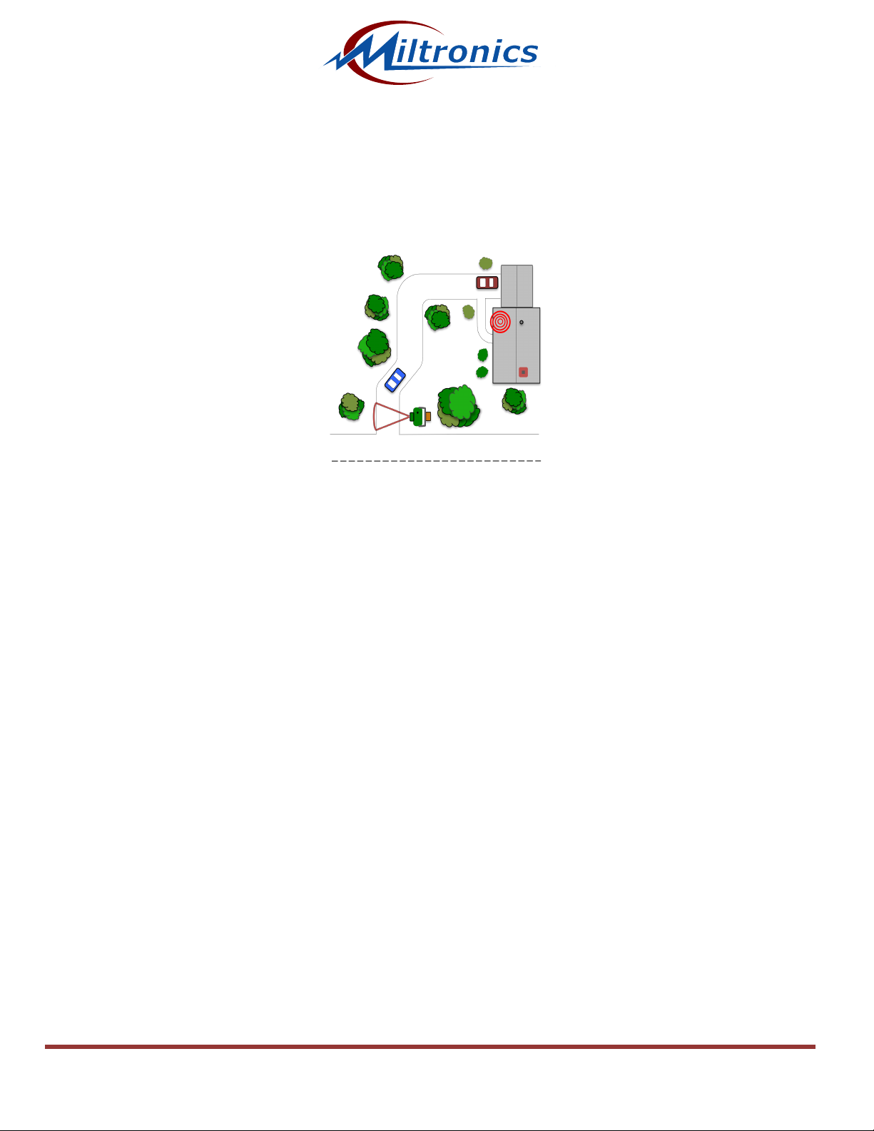
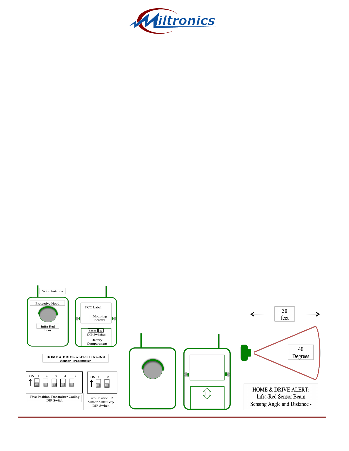
INFRA RED SENSOR TRANSMITTER OPERATION AND INSTALLATION: The infrared sensor is positioned behind
the round IR filter lens. It has a horizontal detection angle of 40 degrees and a detection range of over 30 feet. See
diagram below. The optimum target range is 10 to 15 feet from the Sensor Transmitter. The infrared sensor detects
vehicles, intruders, etc., by sensing their heat and motion. When a vehicle or large warm object moves through the
detection zone, the Infra Red Sensor Transmitter detects the intrusion and transmits a signal to the receiver. When
the battery’s voltage has dropped below the sensor’s required operating voltage, transmissions are sent to the
Receiver until the battery voltage becomes too low to transmit.
First, install a high quality 9-volt alkaline battery in the compartment located in back of the sensor case. Securely
close the battery cover. The Battery will last about six months under normal use. Mount the sensor approximately 2 to
2.5 feet above the ground to a tree, wooden post or side of a building. A Metal Mounting Bracket and Mounting
Screws are provided. Refer to the System Set-Up on page 4. Perform the “Walk Test” (see page 3) prior to
mounting permanently.
The Sensor Transmitter’s IR Lens and infrared sensor must have an unobstructed view of the detection area that is
free of plants, shrubs and branches. Take care not to touch the Lens or allow the Lens to get damaged. Straighten
and extend the flexible antenna straight upward. Some objects may not be detected if the sensor is placed too high or
too low. Adjusting may be required prior to calling for technical support. Keep the sensor as close to the edge
of the driveway as possible. The sensor should be strategically located so that it detects objects moving across
detection zone. Do not mount the sensor facing the sun, bodies of water or any large reflective objects. This causes
variations in the temperature pattern "seen" by the sensor windows and may cause false alarms or damage the lens.
PLEASE NOTE: A shorter transmission range may occur when the outside temperature falls below 20 degrees F. due
to a natural drop in battery voltage. Lower sensitivity may occur during periods of heavy fog, rain or snow. This is due
to the moisture diffusing the infrared energy. The Sensor Transmitters are completely weatherproof and will operate to
-40 degrees Fahrenheit.
TRANSMITTER CODING ADJUSTMENT: The system coding is factory pre-set and should be adjusted only in the
event of interference from another source. Remove the battery cover to access the Five Position Coding DIP-Switch.
The DIP-Switch settings in the Sensor/Transmitter must match the settings in the Receiver. See diagram below.
SENSOR SENSITIVITY ADJUSTMENT: The Infra Red Sensor is located in the Transmitter Case behind the Infra
Red Lens. There is a two-position DIP-switch to adjust the Sensor’s Infra Red Sensitivity. This is factory pre-set and
should not be adjusted without consulting with Technical Support. In typical installations, changing these settings will
cause extremely erratic system behavior. See diagram below.
 Loading...