

Page 1
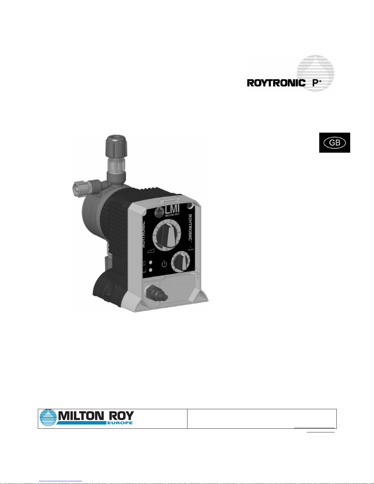
Instructions Manual
Roytronic Série P
+
Electronic Metering pumps
10. Grande Rue
27360 Pont Saint Pierre (FRANCE)
TEL: +(33) 232-683-000
FAX: +(33) 232-683-093
www.miltonroy-europe.com
Lit# 1990.7 8/2007
Page 2
For file refer ence, ple ase record the following data:
Model No. : ______________________________________
Serial Nr:_________________________________________
Installation Date:: ________________________________
Installation Location:______________________________
When ordering replacement parts for your LMI Metering Pump
or Accessory, please include complete Model Number and
Serial Number of your unit.
Carefully read and understand all precautions before
installing or servicing any metering pump
DE ES
FR
IT
NL PT
GB
Page 3

3
Contents
1.0 Precautions .................................................................................................................................................. 4
2.0 Introduction................................................................................................................................................... 5
2.1 Specifications .......................................................................................................................... 5
2.2 Unpacking check list ................................................................................................................ 5
3.0 Installation .................................................................................................................................................... 6
3.1 Pump l oc at io n an d in st al lat io n ................. ........ ...... ........ ...... ........ ...... ........ ......... ..... ........ ........ 6
3.2 Pump mounting ........................................................................................................................ 6
3.2.1 Flooded suction........................................................................................................................ 6
3.2.2 Suction lift - Wall bracket mount ....... ........ ...... ........ ..... ......... ........ ...... ........ ...... ........ ...... ...........6
3.2.3 Suction lift - Tank mo un t.......... ...... ........ ...... ........ ...... ........ ...... ........ ........ ...... ........ ...... ..............6
3.2.4 Suction lift - Shelf mou nt.......... ...... ........ ...... ........ ......... ..... ......... ..... ........ ...... ........ ...... ..............7
3.3 Tubing connections ...................................................................................................................7
3.4 Four-Function Valves (4-FV).....................................................................................................7
3.5 Four-Function Valve Installation ...............................................................................................8
3.6 FastPrime
™
................. ................... ............................................................................................8
3.7 Foot valve/Suction tubing installation .......................................................................................8
3.8 Inject i on c h eck v al v e an d dis c h arg e t ubi ng i n st all at io n............... ......... ..... ........ ...... ........ ...... ...9
4.0 Operation ................................................................................................................................................... 10
4.1 Control panel...........................................................................................................................10
4.2 Start-up and adjustment.......................................................................................................... 11
4.2.1 Start-up/Priming for FastPrime
™
heads ............ ........ ..... ......... ..... ......... ..... ........ ...... ........ ....... 11
4.2.2 Start -u p/ Pr im ing fo r p ump su pp lie d wit h 4- FV .... ......... ..... ........ ...... ........ ...... ........ ......... ..... .... 11
4.2.3 Start -u p/ Pr im ing wit h out 4- FV.................. ........ ...... ........ ...... ........ ...... ........ ...... ........ ........ ...... . 12
4.3 Output adjustment...................................................................................................................12
4.3.1 Total pump output ................................................................................................................... 12
4.3.2 Calib ration in Int e rn al m od e............. ........ ...... ........ ...... ........ ........ ...... ........ ...... ........ ...... .........12
4.3.3 Calib ration in Ext er n al mo d e....................... ........ ...... ........ ...... ........ ...... ........ ........ ...... ............13
4.4 Methods of ext ernall y tr iggeri ng or paci ng P
+
3 P+7, and P+8........................ ..........................13
5.0 Spare Parts Replacement and routine maintenance...................................................................................14
5.1 Depressurizing the discharge line (for pumps equipped with a 4-FV only) 14
5.2 Depressurizing the discharge line (for single ball FastPrime
™
heads o nl y) . ........ ...... ........ .... 14
5.3 Liquifram
™
(Diap hra gm) repla cem en t.... ......... ........... ........... ........ ........... ......... ........... ........ ....15
5.4 Cartr id g e va lve a n d O- Ri ng r ep la c em ent......... ...... ........ ...... ........ ...... ........ ........ ...... ........ ...... .16
5.5 Inject i on c h eck v al v e par ts re pla c eme nt............. ......... ..... ......... ..... ........ ...... ........ ...... ........ .... 16
5.6 FastPrime
™
valve O -R in g re p lac em en t. ...... ........ ...... ........ ...... ........ ...... ........ ..... ......... ........ .... 17
5.7 Stro k e l e ngth setting r e p la c e me n t ... ... ..... ... ...... ..... ... ..... ... ...... .. ...... ... ..... ... ...... ..... ... ...... .. ...... . 17
5.8 EPU wiring diagram.................................................................................................................18
5.9 Liquid e nd p art s list ...... ...... ........ ...... ........ ...... ........ ...... ........ ...... ........ ........ ...... ........ ...... .........18
6.0 Troubleshooting...........................................................................................................................................19
7.0 Annex : Figures............................................................................................................................................ I - XI
Page 4
4
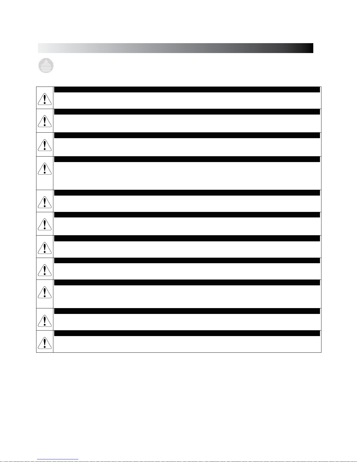
1.0 PRECAUTIONS
The following precautions should be taken when working with LMI metering pumps. Pleas e r e ad th is sec t ion c areful ly p ri or to installation.
Protective Clothing
ALWAYS wear protective clothing, face shield, safety glasses and gloves when working on or near your metering pump. Additional precautions
should be taken depending on the so l utio n being pump e d . Refe r to MSDS preca u t ions from your s o lution suppli e r .
Water Pre-Prime
All LMI pumps are pre-primed with water when shipped from the factory. If your solution is not compatible with water, disassemble the Pump
Head Assembly. Thoroughly dry the pump head, valves, seal rings, balls and Liquifram
™
(diaphragm). Reassemble head assembly
tightening screws in a crisscross pattern. Refill the pump head with the solu tion to be pumped before priming the pump. (This will aid in priming. )
Solution Compatibility
Determine if the materials of construction included in the liquid handling portion of your pump are adequate for the solution (chemical) to be
pumped. LMI pumps are tested b y NS F f o r u s e o n muria t i c a c i d a n d s o d i u m h ypochlor i t e . Al way s re f e r to t h e s o lution supplier and the LMI
Chemical Resistance Ch art for compatibility of your specific LMI metering pump. Contact your local LMI distributor for further information.
Tubing Connec tions
Inlet and outlet t ubin g or pipe size s must n ot be re duce d. Outlet tu bing size must no t be incr ea sed. M ake ce rtain th at any tubing is SECURELY
ATTACHED to fittings prior to start-up (se e S ecti on . , Tu bin g C on necti on s). A L WAYS u se LMI su ppli ed t ubin g wi th y our pump, as the tubing i s
specifi ca lly d e s igned for use wi th th e pump f i t ting s . I t is recommended that all tubing be shielded and secure to prevent possible injury in case
of rupture or accidental damage. If tubing is exposed to sunlight, black UV resistant tubing should be installed. Check tubing frequently for cracks and
replace as necessary ..
Vinyl Tubing
Your carton may contain a roll of clear vinyl tubing; this is only for connection to the return line of the FastPrime
™
Head and must not be
used as discharge tubing.
Fittings and Machine Threads
All LMI pumps have straight screw machine threads on the head and fittings and are sealed by the O-rings. DO NOT use Teflo n
®
tape or pipe
dope to seal threads. Teflon
®
Tape may only be used on the 1/2" NPT thread side of the Injection Check Valve, the stainless steel liquid end connections, or if
piping is directly connected to the pipe threads of the suction or discharge fittings.
Plumbing
Always adhere to your local plumbing codes and requirements. Be sure installation does not constitute a cross connection. Check local plumbing
codes for guidelines. LMI is not responsible for improper installations.
Back Pressure/Anti-syphon valve
If you are pumping downhill or into low or no pressure system, a back pressure/antisyphon device such as LMI’s Four-Function Valve
should be installed to prevent overpumping or syp ho ni n g. Con tact your LM I di st r i bu to r fo r f urther infor mation.
Electrical Connections
WARNING: To reduce the risk of electrical shock, the metering pump must be plugged into a properly grounded grounding-type receptacle with
ratings conforming to the data on the pump control panel. The pump must be connected to a good ground. Do n ot us e adapters! All wiring must
conform to local electrical codes. If the supply cord is damaged, it mu s t be r eplaced by the manufacturer, s tocki ng di strib u tor, or authorized
repair center in order to avoid a hazard.
Line Depressurization
To reduce the risk of chemical splash during disassembly or maintenance, all installations should be equipped with line depressurization
capability. Using LMI’s Four-Function Valve (-FV) is one way to include this feature.
Ground Fault Circuit Interrupter
WAR NI N G : To r e du c e t he risk of el e ct r i c s ho c k , i n s ta l l on ly o n a ci r c u it p ro t e ct e d b y a Ground Fault Circuit Interrupter (GFCI).
PRECAUTIONS
Page 5
5
2.0 Introductio n
LMI is the world’s most versatile manufacturer of economical and efficient metering
pumps. This manual addresses the installation, maintenance and troubleshooting procedures for manually and externally controlled pumps. LMI has a worldwide network of
stocking representatives and authorized repair centers to give you prompt and efficient
service.
Please review this manual carefully. Pay particular attention to warnings and
precautions. Always follow good safety procedures, including the use of proper
clothing, eye and face protection.
This man u al is fo r Roytron ic™ Series P+ pumps.
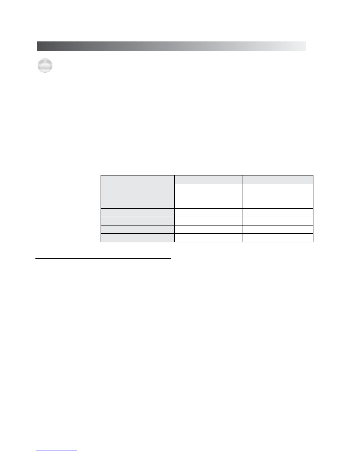
2.1 Spécifications
P+XX1 & P+XX8 P+XX2 to P+XX7
Operating temperature
14 to 113°F
–10 to 45°C
14 to 113°F
–10 to 45°C
Voltage
110 to 120 V 220 to 240 V
Frequency
50 to 60 Hz 50 to 60 Hz
Max. Current
0.66 A 0.34 A
Wattage
39 W 42 W
Fuse Sp ecific a t ion
1.25 AHT (5 x 20 mm) 1.25 AHT (5 x 20 mm)
2.2
Unpacking che ck list
Your carton will contain many or all of the following items. Please notify the carrier
immediately if there are any signs of damage to the pump or its parts.
- Metering pump ( See annex fig. 1)
- Foot va lve (See annex fig. 2)
- Vinyl tubing (for Fastprime
TM
) (See annex fig. 3)
- Ceramic foot valv e weight (See annex fig. 4)
- Injection check - valve (See annex fig. 5)
- Four-Functi on Valve(O ptional ) (See annex fig. 6)
INTROD
UCTION
Page 6
6
3.0 Installation
3.1 Pump Location and Installatio n
Locate pump in an area convenient to solution tank and electrical supply.
The pump should be accessible for routine maintenance, and should not be operated in ambient
temperatures above 113°F (45°C). If the pump will be exposed to direct sunlight, LMI black, UV
resistant tubing should be installed
.
3.2 Pump Mounting
The pump can be mounted in one of two ways:
A. FLOODED SUCTION (ideal installation);
or
B. SUCTION LIFT - when suction lift is less than 5 feet (1.5 m) for solutions having a specific gravity
of water or viscosity of less than 100 cSt (centistokes). For denser or more viscous solutions,
consult distributor.
Your LMI metering pump must be mounted so that the suction and discharge valves are vertical.
NEVER position pump head and fittings horizontally.
3.2.1 Flooded Suction
For flooded suction the pump is mounted at the base of the storage tank. This installation is the
most trouble-free, and is recommended for very low outputs, solutions that gasify, and highviscosity solutions. Since the suction tubing is filled with solution, priming is accomplished quickly
and the chance of losing prime is reduced. A foot valve is not necessary in a flooded suction
installation.
When pumping downhill or into low or no pressure system, a back pressure/anti-syphon device
should be installed to prevent overpumping or syphoning.
Although popular for all solutions, LMI recommends flooded suction installations for all highviscosity fluid applications.
- INCORRECT (See annex fig. 7)
- CORRECT (See annex fig. 8)
3.2.2 Suction Lift - Wall Br acket Moun t
The pump may be mounted using an LMI Wall Mount Bracket Assembly directly above the solution tank.
A pump mounted in this manner allows for easy changing of solution tanks or drums
.
3.2.3 Suction Lift - Tank Mount
The pump may be mounted on a molded tank provided there is a recess to keep the pump stationary.
3.2.4 Suction Lift - Shelf Mount
The pump may be mounted on a shelf (customer supplied) maintaining a suction lift of less than 5 ft ( 1.5
m). (See annex fig. 9 and fig. 10)
INSTA LLATION
Page 7
7
3.3 Tubing Connections
A. Use only LMI tubing.
B. DO NOT USE CLEA R VIN YL TU BING O N THE DI SCHAR GE SI DE OF THE PUM P.
The pressure created by the pump can rupture vinyl tubing, which is only for connection to
the return line of the FastPrime
™
fitting.
C. Before installation, all tubing must be cut with a clean square end.
D. Valve and head connections from the factory are capped or plugged to retain pre-prime water.
Remove and discard these caps or plugs before connecting tubing.
DO NOT USE PLIERS OR PIPE WRENCH ON COUPLING NUTS OR FITTINGS.
To assemble tubing into the fittings:
1. Put coupling nut (A) over tubing.
2. Press on tubing sleeve (B) about one inch (25 mm).
3. For 1/4" or 6mm tubing, (10mm) tubing protrudes from the sleeve (B). For all other tubing
push tube to the bottom of groove in end cap (C).
4. Tighten the coupling nut (A) onto the fitting (D).
Legend figure : (See annex fig. 11)
A : Coupling nu t
B : Tubing sleeve
C : End cap D : Fitting
3.4 Four-Function Valves (4-FV)
Your pump may be equipped with a 4-FV, or standard discharge valve. If your pump is not equipped
with a four-funct ion valve and you feel it is need ed in your application, it can be purchased as an
accessory. Contact your local LMI stocking distributor. The features of a 4-FV are listed below.
(see fig.12 – 13)
1. Pressure Relief: If the discharge line is over pressuriz ed, the valve opens sending sol ution back to
the supply tank.
2. Line Depressurization: Opening the relief knob provides line drain back to the supply tank.
3. Anti-Syphon: Pre v ents syphoning when pumping solution downhill or into a vacuum.
4. Back Pressure: Supplies approximately 1.7 bars (25 psi) back pressure to prevent overpumping
when little or no system back pressu re is present.
3.5 Four-Function Valve Installation
To install the 4-FV, remove valve housing and upper cartridge screw in the valve and hand tighten. An
additional 1/8 - 1/4 turn may be necessary to prevent leakage.
6.35 mm. (1/4") tubing connects to the side of the valve and acts as a return line to the solution
tank. To ensure priming, this tubing must NOT be submerged in the solution.
Legend figure : (See annex fig. 14)
A : 6.35 Tubing,
B.:Connector,
C.:Discharge,
D.:To solution tank or
drum,
E.:Bottom tubing in fitting Push and
hold while tightening connector,
F.:To Pump Head
This return line tubing must be secured to ensure pumped solution will safely return to supply tank
INSTALLATION
Page 8

8
3.6 FastPrime
TM
valve
The FastPrime™ Head is equipped with a valv e that allows for opening the head t o atmospheric
pressure. When installing a pump equipped with a FastPrime
™
Head connect the 3/8" outer diameter
clear vinyl tubing provided with the pump to t he barbed nozzle. Route t h e v inyl return line b ack t o t he
solution tank. This tubing must not be submerged in the solution.
FastPrime
TM
system (See annex fig. 15)
3.7 Foot Valve/Suction Tubing Installation
The Foot Valve acts as a check valve to keep the pump primed in suction lift applications.
The foot valve is designed to be submersed in the solution tank or drum and must sit in a vertical position at the bott om.
Position approximately 2 inches (50 mm) off the bottom if the tank or drum contains sediment.
The ceramic weight, when installed, helps position the foot valve in a vertical position.
1. Attach the foo t valve to one end of the suction tubing (see Tubi ng Conne ctions , Section 3.3).
2. Slide the ceramic weight over the tubing end until it contacts the top of the foot valve coupling nut.
3. Place foot valve and tub ing into the solu tion tank. Che ck that t he foot valve is ver t ical and
approximately 2 inches (50 mm) from the bottom of the tank or drum (see illustration).
Connect the other end of the tubing to the suction side of the pump head (bottom side) (see
Tubing Connections, Section .3.3).
- INCORR E C T Tilt e d side ways w i ll not prime ( See annex fig. 16)
- CORRECT Foot valve must remain vertical
Legend figure : (See annex fig. 17)
A : Return lines must not
be submerged
B : Use ceramic weight C : 2.0 in. (50 mm) for sediment
accumulation
3.8 Injecti o n Che c k V alv e an d D is ch arg e
Tubing Installation
The Injection Check Valve prevents backflow from a treated line. Install the injection check
valve at the location where chemical is being injected into the system. Any size NPTF fitting or
pipe tee with a reducing bushing to 1/2" NPTF will accept the injection check valve. Use Teflon
®
tape or pipe dope to seal the pipe threads only.
When installing the Injection Check Valve, be sure to position it so that the valve enters the bottom
of your pipe in a vertical position. Variations left and right within 40° are acceptable (see
illustration).
After cutting an appropriate length of tubing, connect tubing to the injection check valve then back
to the discharge side o f the pump hea d. Make sure it does no t crimp or come into contact with hot or
sharp surfaces (see Tubing Connections, Section 3.3.).
Typical injection check valve installation
Legend figure : (See annex fig. 18)
A : 1" Pipe tee.
B : Reduction 1' to 1/2".
C : Injection check valve.
D : Flow
E : CORRECT Use Teflon tape here on
pipe th reads only.
F : Do NOT use Teflon tape on
machined threads.
G : 40 ° Variation accep table.
H : Injection check valve.
I : Flow.
Pump
models
equipped
with
high
viscosity
liquid ends
are not
equip
ped
INSTA LLATION
Page 9

9
4.0 Operation
4.1 Control panel (Fig. 19)
1. Power/Mode Selection Button: This button allows convenient starting and stopping of the pump.
For pumps with external control capability (P
+
3, P+7, P+8) this button switches pump operation
between internal and external modes. When operating in internal mode the Pulse Indicator Light
will flash green. When operating in external mode the Pulse Indicator Light will flash yellow.
2. Speed Adjustment Knob:
This knob provides adjustment of the stroking speed. For pumps with
this knob (P
+
1, P+7, P+8) turning this knob clockwise increases stroke frequency (speed) from a
minimum of 1 stroke per minute.
3. Stroke Adjustment Knob:
This knob provides adjustment of the stroke length. Turning this knob
clockwise increases the stroke length, which results in a higher amount of chemical displaced
per stroke. It is recommended that the stroke range stay between 20% and 100%.
4. Pulse Indicator Light:
This light will flash gree n whe n pu mpin g in inter n al mode, and will flash
yellow when pumping in external mode. The light is on between strokes and off during the actual
stroke.
5. Low-Level Indicator Light:
This light wi ll tu rn red when a Lo w- Lev el Se nso r re gist ers a low
che mical le ve l. Th is wi ll turn off th e pump . Y ou mu st have a Low-Le v el Sens or connect ed to the
pump through the Low-Level Connector for this function to operate.
6. Low-Level Connector (3-Pin) Fig.20:
This connector is for the connection of a Low-Level Sensor
(48413). The low -le v e l s witch inp ut co nn ec t ion s a r e always active for all models in all functional
modes. If the fluid level drops below the l eve l spec ifi ed by t he Low-Lev e l Sens or, t he pump wil l stop
and the Low-Level Indicator Light will turn on. The pump is designed to recognize an open circuit as
full, and a closed circuit as empty. The pin functions are as follows:
1. Low level signal
3. No connection
4. Low level return
7. External Control Connector (5-Pin)Fig.21: This connector is for the connection of various options
and accessories that can be used to externally control the pump. The pin functions (and the wire
color for the standard LMI external control cable) are as follows:
1. Remote On/Off Signal (Brown)
2. Ground/Common (White)
3. External pulse signal (Blue) (used only with P
+
3, and P+7 pumps).
4. 18 Volt DC. Supply voltage (Black)
5. 4-20mA, input signal (Green/Yellow) (used only with P
+
8 pumps).
Some of the accessories available for use with P+ Series metering pumps are listed below. Note that an
Adapter Cable (48488) is needed when connecting any of the MICROPACE(TM) units (Fig.23).
A. MICROPACE
™
A/D Converter (MP-100) - for translating a -20 milliamp signal into pulses.
B. MICROPACE
™
Divider (MP-400D) - for reducing the frequency of high frequency pulses.
C. MICROPACE
™
Multiplier (MP-500M) - for increasing the frequency of low frequency pulses.
D. Pulse Tra nsmitter (48489) - for pulsing i n ti me with another LMI Elect ronic Metering Pump.
E. RFP Flowmeter and Programmable Divider - for pacing the stroke frequency off of the system
flow.
F. FC Flowmeter/Contactor - for pacing the stroke frequency from the system flow.
OPERATION
Page 10
10
4.2 Start-up and Adjustment
•
The pump is normally self-priming if suction lift is 5 ft (1.5 m) or less and the steps below are
followed
•
Pumps are shipped from the factory with water in the pump head to aid in priming.
4.2.1 Start-Up/Priming for FastPrime™ Heads
Read this entire section completely before proceeding.
When all precautionary steps have been taken, the pump is mounted, and the tubing is securely
attached, you may now start priming the pump.
1. Plug in or switch the pump on.
2. While the pump is running, set the Speed Adjustment Knob and the Stroke Adjustment Knob
at 100%.
3. Turn The FastPrime
™
knob 1 to 2 turns counter-clockwise.
4. The suction tubing should begin to fil l w ith solution from the tank.
5. A small amount of solution will begin to discharge out the return line of the FastPrime
™
valve.
Once this happens, turn the knob clockwise P until hand tight and SHUT THE PUMP OF F.
6. The pump is now primed.
7. Proceed to output adjustment, Section 4.3
4.2.2 Start-Up/Priming for Pump
Supplied with 4-FV
Read this entire section completely before proceeding.
When all precautionary steps have been taken, the pump is mounted, and the tubing is
securely attached, you may now start priming the pump.
1. Plug in or switch the pump on.
2. While the pump is running, set the Speed Adjustment Knob and the Stroke Adjustment
Knob at 100% .
3. 1/4 t urn open the reli ef side (black knob) of the 4-FV.
4. The suction suction tubing should begin to fill with solution from the tank.
5. A small amount of solution will begin to discharge out the return line of the 4-FV. Once this
happens, 1/4 turn or release the knob and SHUT THE PUMP OFF.
6 . The pump is now primed.
7. Proceed to output adjustment, Section 4.3.
4.2.3 Start-Up/Priming for without 4-FV
Read this entire section completely before proceeding.
When all precautionary steps have been taken, the pump is mounted, and the tubing is
securely attached, you may prime the pump.
1. Plug in or switch on the pump.
2. While the pump is running, set the speed knob and the stroke knob at 100%.
3. The suction tu b i n g should begin to fill with so l ution from the tank .
4. Once the solution begins to exit the pump head on the discharge side,
SHUT THE PUMP OFF.
5. The pump is now primed.
6.
Proceed to output adjustment, Section 4.3.
If the pump does
not self-
prime,
remove the
4-
FV on the
discharge
side of
the pump head.
Remove the check
valve and for water
or solution into the
port until the head
is filled. Replace
valve,then follow
start up/Priming
steps
If the pump does
not self-
prime,
remove the
discharge check
valve and pour
water or solution
into the port until
the head is filled.
Replace valve,
then follow start
up/priming steps
OPERAT
ION
Page 11

11
4.3 Output A dju st men t
Once the pump has been primed, an appropriate output adjustment MUST be made. Pump
output should be calculated and adjustments made accordingly.
4.3.1 Total Pump Output
Calculate the approximate output of the pump as follows:
PUMP OUTPUT = MAX PUMP OUTPUT x % SPEED x % STROKE
Use Max Output (from data plate on side of pump) = 1 GPH (1 gallon per hour).
If the pump is set at 60% speed and 70% stroke length, the approximate pump
output is:
1.0 x 0.60 x 0.70 = 0.42 GPH.
Multiply by 24 (hours in one day) to calculate in gallons per day. If pump is not equipped with speed
adjustment, calculate by Ma x Pu m p Out put x % St r o ke l e ngth only.
4.3.2 Calibration in Internal Mode
Once installation is complete and the approximate output has been determined, the pump should be
calibrated to adjust speed and stroke for your actual desired output. (Calibrat ion cylind ers ma y be
purchased from your local LMI distributor)
1. Be sure the pump is primed, and discharge tubing and Injection Check Valve are in stalle d as th ey
would be in norm al serv ice (i.e. , includi ng fac tors such a s injection pressure, fluid viscosity, and
suction lift).
2. Place the Foot Valve in a graduated container with a volume of 1000 ml or more.
3. Plug in and switch pump to Internal Mode. Pump until all the air is exhausted from t he su ctio n line
and head.
4. Turn the pump off. Refill graduated container to a level starting point.
5. Using a st opwatch or timer, turn t he pump on for a m easured amount of t ime (120 pump strokes
minimum). The lon ger the time period is, th e more confident yo u c an be o f t he r esu lt s. B e s ur e t o
count the number of strokes during the calibration period when making comparisons.
6. Turn the pump off. Note t he time elapsed in relation to volume displaced in the graduate. Now,
calculate the output in the time unit you choose (minutes, hours, days, etc.).
7. If the output is too low or too gre at, use t he Stroke A djustment Knob and/ or th e Spe ed A dj us tme nt
Knob to fine-tune the amount of flow, estimating required correction and repeat steps 1-.
(See annex fig. 22)
When converting
between different
units, remember
these conversion
factors: 1 Gallon =
3.785 liters 1 Day =
1.440 Minutes 240
SPM = 14.400 SPH
OPERATION
Page 12

12
4.3.3 Calibration in External Mode
1. Be sure the pump is primed, and discharge tubing and injection check valve are installed as they
would be in normal service (i.e., including factor such as injection pressure, fluid viscosity and
suction lift).
2. Place the foot valve in a graduated container with a volume of 100 ml or more.
3. Plug in and switch pump to internal mode. Pump until all the air is exhausted from the suction line
and head.
4. Switc h pump OFF and refill graduate to a starting point.
5. Switch pump ON and count the number of strokes for exactly one minute, then switch pump
OFF.
6. Note volume pumped during the calibration period of one minute. Divide into this the number
of strokes to determine the volume of solution pumped per stroke.
Example: 720 ml in 240 strokes = 3.0 ml per stroke.
Multiply this by your expected stroke rate per minute, per hour or per day and compare with
desired output requirements.
7. Turn Stroke Adjustment Knob to your best estimate of required correction and repeat calibration
procedure.
4.4 Methods of Externally Triggering or
Pacing P
+
3, P+7, and P+8 Pumps
Method of Tri gg er ing P+3, and P+7 Pumps Through External Control Connector
*PIN
1. Switch Closure
Switch closing triggers
pump
3
2
2. NPN Transistor
Base goes high to
trigger pump
3
2
3. PNP Transist or
Base goes low to
trigger
3
2
4. Opto Isolator
3
2
Switch or transistors must be capable of switching 24V DC at
15 mA. Minimum time in low impedance state (ON) i s 2 5
milliseconds. Minimum time in high impedance state (OFF) is 50
milliseconds.
To operate in external mode, contact between 1 and 2
(Brown/white) must be closed.
*PIN / Wire color:
2 = White
3 = Blue
It may be
helpful to
decrease the
speed of the
pump in order
to count the
number of
strokes. For
accuracy count
at least 120
strokes
OPERATION
Page 13

13
These pumps have two operating modes: Local (Pulse Indicator Light flashes
green) and Remote (Pulse Indicator Light flashes yellow). Pressing the Power/
Mode Selection Bu tton swi tche s be tween Local an d Remot e modes. The defaul t
configuration for operating mode is Local mode.
When the pump is in Local mode the Remote On/Off input is ignored. When the pump
is in Remote mode the Remote On/Off input is always monitored. The pump will
return to the last power mode if power is interrupted.
4.4.1 Control Modes
4.4.1.1 Local Mo d e
When in Local mode the P+3 pump runs continuously at maximum speed
When in Lo c a l mo de P
+
7 and P+8 pumps run at the speed indicated by the speed knob
4.4.1.2 Remote Mo d e ( fo r P+3, and P+7)
• In Remote mode pulses occurring faster than a rate of 1200 pulses per minute (less than 50 ms) and pulses
with a duration of less than 25 ms are ignored.
• Pulses occurring between 240 strokes per minute (SPM) and 1200 pulses per minute results in the pump
running at 240 SPM.
• Pulses occurring at less than 240 SPM results in the pump stroking at that rate.
4.4.1.3 Remote Mo d e ( fo r P+8)
In Remote mode the pump speed is controlled by a milliamp (mA) Analog Input signal. The factory default settings
for the Analog Input are: 20mA input = maximum speed, 4mA = 0 stroke per minute. The mA input setting can be
calibrated to a ny le vel betw een 0–22 mA. When recalibrating the input settings, the span between high and low input
must be greater than 6mA. If the span is not large enough, the Pulse Indicator Light will flash green and yellow
alternately at about 10 times per second.
In the default settings, the fast level mA input is greater than the slow level mA input. This is known as direct
action. In direct action when the mA input is at or above the setting for the fast level, the pump will run at maximum
speed. When the mA input is below the setting for the slow level, the pump will stop.
Reverse action is when the slow level mA input is greater than the fast level mA input. In reverse action when the
mA input is at or below the setting for the fast level, the pump will run at maximum speed. When the mA input
is above the setting for the slow level, the pump will stop. (See § 4.4.1.4)
4.4.1.4 Calibrating the Analog Input Settings
(for P
+
8)
1. Press and hold the Power/Mode Selection Button for more than 5 seconds. The pump stops.
2. Turn the Speed Adjustment Knob completely clockwise P to enter the fast level analog input state. The Pulse
Indicator Light will flash 1 second green 1/4 second yellow.
3. Apply the desired fast level analog signal and press the Power/Mode Selection Button for less than 3 seconds. The
Pulse Indicator Light will be green for 1 second befo re resuming flashing to confirm storage o f the se t ting .
4. Turn the Speed Adjustment Knob completely counter-clockwise Q to enter the slow level analog input state.
The P u l s e In d icator Li g h t w i l l f l a s h 1 seco n d y e l l o w 1 / 4 secon d green.
5. Apply the desired slow level analog signal and press the Power/Mode Selection Button for less than 3 seconds.
The Pulse Indicator Light will be yellow for 1 second before resuming flashing to confirm storage of the setting.
6. To return the pump to the factory default settings turn the Speed Adjustment Knob to 50%. The Pulse Indicator
Light should flash 1 second green, 1 second y ellow . Then press the Power/Mode Selection Button.
7. To exit calibration mode press and hold the Power/Mode Selection Button for more than 3 seconds.
The def
ault configuration for
the Remote On/Off input is:
open contacts pump
stopped, closed.
Therefore pins 1 and 2 of the
External Control
Connector must be shorted
together in external mode
for the pump to respond to
external signals
.
OPERATION
Page 14
14
5.0 Spare Parts Replacement and Routine Maintenance
LMI recommends replacing the elastomeric components of the pump on an annual basis. Refer to the LMI
Metering Pump Price List for the proper Spare Parts Kit or RPM Pro Pac
™
kit number or contact your local LMI
stocking distributor.
5.1 Depressurizing the Discharge Line
(for Pumps Equipped with a 4-FV Only)
ALWAYS wear protective clothing, face shield, safety glasses and gloves when performing any
maintenance or replacement on your pump.
To reduce the ri sk of chemical splash during disassembly or maintenance, a ll installations sh ould be
equipped with line depressurization capability. Using LMI’s Four-Function Valve (4-FV) is one way to
include this feature
Read steps 1 and 2 below before proceeding.
1. Be sure the Injec tion Check Val ve is prope rly ins talled and is opera ting . If a shut o ff valve has been
installed downstream of the Injection Valve, it should be closed.
Be sure your relief tubing is connected to your 4-FV and runs back to your solution drum or tank.
2. Turn the bl ack knob on the 4-FV 1/4 turn. Pull out and hold the yellow knob for a few seconds. The
discharge line is now depressurized. Keep both valve knobs open until solution drains back down the
discharge tubing in t o solution drum or ta nk. Then release the yellow knob, and 1/4 turn the black knob
to normal position.
5.2 Depressurizing the Discharge Line
(for Single-Ball FastPrime
™
Heads Only)
ALWAYS wear protective cloth ing, face sh i eld, safety glasses and gloves when
performing any maintenance or replacement on your pump.
Read steps 1 and 2 below before proceeding.
1. Be sure the Injection Check Valve is properly installed and is operating. If a shut off
valve
has been installed downstream of the Injection Valve, it should be c losed .
Be sure your relief tubing is connected to your FastPrime
™
valve and r uns back t o your
solution drum o r tank.
2. Turn the FastPrime™ knob one-and-a-half turns counter-clockwise. The discharge line is
now depressurized. Keep valve open until solution drains back down the discharge
tubing into solution drum or tank. Then turn the kno b clockwise
P to tighten knob to closed
position.
MAINTENANCE
Page 15

15
5.3 Liquifram™ (Diaphragm) Repla cement
ALWAYS wear protective cloth ing, face shield, sa fety glasses and gloves wh en wo rk ing ne ar or
performing any maintenance or replacement on your pump. See MSDS information from solution
supplier for additional precautions
1. Carefully depressurize, drain, and disconnect the discharge line (see previous sections in this
manual).
2. Place the Foot Valve into a container of water or other neutralizing solution. Turn the pump on
to flush the head assembly. Once the pump head has been flushed, l if t the Foot Valve out of the
solution and continue to pump air into the pump head until the pump head is purged of water
or neutralizing solution.
If the liquid cannot be pumped due to Liquifram
™
rupture, carefully disconnect the suction and discharge
tubing us ing protective cl othing, glov es and face sh ield. Remove th e four screws a nd washers fr om the
head and immerse the head in water or o ther neut ralizing soluti on.
Legend figure : (See annex fig. 24)
A : Liquid end.
B : Diaphragm.
C: Adaptation.
D :Shaft seal.
E : Drive.
3. Start the pump. While running, set the Stroke Adjustment Knob to 0% and turn the pump off.
4. With the unit off, unscrew the Liquifram
™
by carefully grasping the outer edge and turn ing it
counter-clockwise. Discard old Liquifram
™
. Remove the Adapter Disk (located behind the
Liquifram
™
) and ensure t hat the diameter of the raised section is the sam e as t he d iam ete r of
the replacement Liquifram
™
.
5. Remove Adapter Disk and check condition of the Shaft Seal. Replace Shaft Seal if necessary.
6. Replace t he Adapter D isk so that t he drain hole of the disk is o riented down ward, and the
mounting holes line up with the mounting holes of the pump.
7. Screw on the new Liquifram
™
clockwise until turned all the way i n. St art the pump and turn the
stroke knob to 100%. Stop the pump.
8. Remount the pump head using the four screws and washers. Tighten in a criss-cross
pattern. After one week of operation, recheck the screws and tighten if necessary.
Be careful not to scratch the Teflon
®
face of the new Liquifram™.
MAINTENANCE
Page 16

16
5.4 Cartridge Valve and O- ring
Replacement
ALWAYS wear protective clothing, face shield, safety glasses and gloves when working on or
performing any maintenance or replacement on your pump. See MSDS information from solution
supplier for additional precautions.
Refer to the LMI Meter ing Pum p Price List f or the proper Sp are Parts Kit or RPM Pro P ac
™
kit
number or contact your local LMI stocking distributor.
1. Carefully depressurize and disconnect the discharge line ( see Section 5 .1 or 5 .2 in this manual).
2.
Place the Foot Valve into a conta iner of water or ot her neutra l izi ng solut ion. Turn t he p u mp o n to flus h t he
head assembly. Once the pump has been flushed, lift the Foot Valve out and continue to pump t o let
air into the pump head until pump is purged of water or neutralizing solution.
If the liquid cannot be pumped due to Liquifram
™
rupture, carefully disconnect the suction and discharge
tubing using protect ive clothi ng, gloves and face shield. Rem ove the four scr ews and washers f rom the head
and immerse the head in water or other neutralizing solution.
Spare part replacement kits include specific instructions for valve replacement. Please follow the
instructions included with the replacement kit.
3. Caref ully disconn ect one tubing c onnection a nd fitting at a t ime, then remov e and replace the worn valve
and O-rings. If necessary, carefully loosen stuck v alves by prying side to side using a small screwdriver
through the center hole of the valve.
Before disassembling the check valves, note the orientation of the valve.
4. Install new check valves in each location. Ensure that the cartridges are oriented correctly.
5.5 Injection Check Valv e Parts
Replacement
Depressurize and drain pipeline (or isolate Injection Check Valve point using valves) so that
Injection Chec k Va lve can safe ly b e d isa ss emb led.
1. Isolate Injection Check Valve and depressurize pipe or drain pipeline.
2.
Carefully depressurize and disconnect the discharge line (see section 5.1 or 5.2 in this manual)
Before disassembling the check valve, note the orientation of the parts.
3. Install a new spring, seat, ball, and O-ring. Ensure that the parts are oriented correctly.
Legend figure : (See annex fig. 25)
A: Spring.
B: Ball.
C: O-Ring .
D: Seat.
E: Injection check valve fitting.
MAINTENANCE
Page 17

17
5.6 FastPrime™ Valve O-Ring Replacement
Depressurize and drain pipel ine (or isolate Injectio n Check Val ve po int us ing va lves) so tha t Inj ection
Check Valve can safely be d isas sembled.
ALWAYS wear protec tive clo thing, fa ce shield , safety glasses and gloves when perfo rming any
maintenance or replacement on your pump.
Refer to the LMI Metering Pump Price List for the proper Spare Parts Kit or RPM Pro Pac
™
kit number or
contact your local LMI stocking distributor.
1. Be sure the In jec tion Ch eck Valve is prope rly in stall ed and is ope ra ting . If a s hut of f valve has been ins talled
downstream of the Injection Valve, it sh ould be closed.
2. Turn the FastPrime
™
Knob one-and-a-half turns counter-clockwise Q. This will depressurize the
head. Keep valve open. Ca refu ll y remov e the ret ur n line by gent l y pullin g tu b ing a nd mo vi n g it fr om s ide
to side to gradually back tubing off of the barbed fitting.
3. Hold ret urn lin e t ubi ng upr i ght u nt il so lu t ion dr ai ns ba c k i n to s o lut i on d r um or t an k.
4. Using a 11/16" (or 17 mm) socket or wrench remove the Retaining Nut, and pull out
the entire FastPrime
™
Valve assembly. Remove and replace the two small O-rings.
5. Reinsert the FastPrime
™
Valve assembly and retighten the Retaining Nut. (17 m m or 11 /1 6 " wren ch)
Then turn the FastPrime
™
Knob clockwise to tighten knob to closed position.
6. Recut 1 to 2 inches off the tip of the return line and ensure the end is squared. Press the return line tubing on
completely past the barbs.
Legend figure : (See annex fig. 26)
A – E : O-Rings
B – H : FastPrime
™
valve
C – F : Nut
D : Knob
I : Tubing
G : Retaining ring
5.7 Stroke Length Replacement
The Stroke Adjustment Knob is calibrated for each pump, and does not need to be removed
during Liquifram
™
replacem ent or dur ing mos t other m aint enanc e. If the Strok e Knob is removed for
any reason it becomes necessary to reset the stroke length. Follow the procedure below to
approximate the proper factory setting.
1. Install a n ew Stroke Shaft. Not e that there will be so me resistance as the O-r ing slides in to t he
control panel. The Stroke Knob can be used to turn the Stroke Shaft. Continue to turn the
Stroke Shaft until there is no longer any diaphragm movement. It may be neces sary t o t urn on
the pump in order to get the Stroke Knob completely forward; however, care should be taken
to ens ure t hat the Str oke Shaf t is cont ac ting th e Plung er before turning on the unit. Otherwise
the pump could be damaged.
2. Once the Stroke Shaft is completely forward, you can reset the stroke length.
a. On P
+
X5, P+X6, and P+X9 pumps press in the Stroke Knob so that the Stroke Knob Pointer
indicates 0 (zero).
b. For P
+
X1, P+X4, and P+X8 pumps press the Stroke Knob in at 50 and turn the knob to point at
100. Then remove the Stroke Knob and reinsert so that the Stroke Knob Pointer is indicating 50
again.
3.
Use a Phillips head screwdriver to install the Stroke Knob Screw.
4. Insert the Stroke Knob Pointer into the Stroke Knob.
Legend figure : (See annex fig. 27)
A : Stroke knob pointer.
B : Screw.
C : Knob.
D : O-Ring.
E : Shaft.
MAINTENANCE
Page 18

18
5.8 EPU Wiring Di agr am
Legend figure : (See annex fig. 28)
A : Pulser.
R : Power cord.
W : White or Blue.
B : Black or Brown.
L : Green or Green/Yellow.
Y : Yellow.
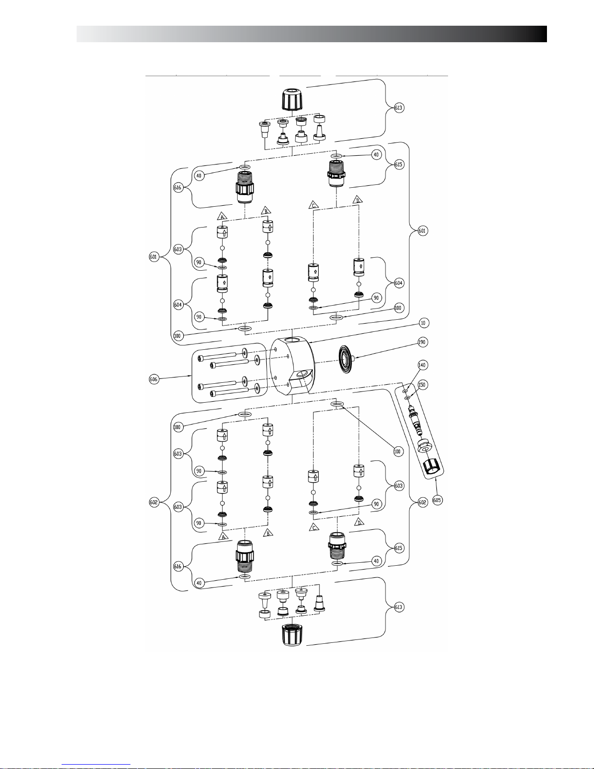
5.9 Liquid End Parts List
Description
10 Pump head
20 Single ball check valve f itti n g
25 Double ba ll check valve fit ting
30 Coupling nut
40 Tube connectin O-Ring
90 Seat O-Ring
100 Cartridge valve O-Ring
140 FastPrime™ Valve gasket
150 FastPrime™ Valve O-Ring
180 Liquid End cover
190 Liquifram™
200 Injection valve s eat
210 Injection ball
220 Injection spring
230 Injection check valve body
240 Injection flapper valve
250 Ceramic weight
260 Foot valve body
270 Foot valve strainer
601 FastPrime™ discharge ch eck valve
602 Suction check valve
603 Cartrigde valve
604 FastPrime™ cartridge valve
605 FastPrime™ valve
606 Liquid End hardware
607 Foot valve
608 Injection valve
609 Autoprime™ discharge valve
611 Autoprime™ valve
612 Autoprime™ cartridge
613 Connection kit
615 Valve body
- Injection valve (See annex fig. 29A)
- Foo t Va lve (See annex fig. 29B)
- Machined FastPrime
TM
liqu id end (See annex fig. 30)
- Molded FastPrime
TM
liquid end(See annex fig. 31)
- AutoPrime
TM
liquid end (See annex fig. 32)
MAINTENANCE
Page 19

19
6.0 Troubleshooting
PROBLEM
POSSIBLE CAUSE
SOLUTION
1. Pump not turned on or plugged in 1. Turn on pump / pl ug in pump.
2. Output dials not set properly 2. Always prime pump with speed and stroke at
100%.
3. . Foot Valve not in vertical position
on bottom of tank
3. Foot Valve must be vertical (see Foot Valve
Installation, Section 3.7).
4. Pump suction lift too high 4. Maximum suction lift is 5 ft (1.5 m). Pumps
with High Viscosity Liquid Handling Assemblies
require flooded suction.
5. Suction tubin g is curved or coiled in
tank.
5. Suction tubing must be vertical. Use LMI
ceramic weight supplied with pump (see Section
3.7).
6. Fittings are over tightened. 6. Do not over tighten fittings. This causes seal
rings to distort and not seat properly which
causes pump to leak back or lose prime.
7. Air trap in suction valve tubing. 7. Suction tubing should be as vertical as
possible. AVOID FALSE FLOODED SUCTI ON!
(see Section 3.2.1).
Pump Will Not Prime
8. Too much pressure at discharge.
(Pumps without multi-function valve.)
8. Shut off valves in pressurized line.
Disconnect tubing at injection check valve (see
Priming Section 4.2). When pump is primed,
reconnect discharge tubing.
1. Solution container ran dry. 1. Refill container with solution and reprime (see
Section 4.2).
2. Foot Valve is not in a vertical position
on the bottom of the tank.
2. Foot Valve must be vertical (see Foot Valve
Installation, Section 3.7).
3. Pump suction lift is too high. 3. Maximum suction lift is 5 ft (1.5 m). Pumps
with High Viscosity Liquid Handling Assemblies
require flooded suction.
4. Suction tubin g is curved or coiled in
tank.
4. Suction tubing must be vertical. Use LMI
ceramic weight supplied with pump (see Section
3.7).
5. Fittings are over tightened. 5. DO NOT OVERTIGHTEN FITTINGS. This
causes seal rings to distort and not seat
properly which caused pump to leak back or
lose prime.
Pump Loses Prime
6. Air trap in suction valve tubing. 6. Suction tubing should be as vertical as
possible. AVOID FALSE FLOODED SUCTI ON!
(see Section 3.7).
TROUBLESHOOTING
Page 20

20
6.0 Troubleshooting
PROBLEM
POSSIBLE CAUSE
SOLUTION
1. Worn tubing ends. 1. Cut about 1 in (25 mm) off tubing and then
replace as before
2. Loose or cracked fitting. 2. Replace fitting if cracked. Carefully hand
tighten fittings. DO NOT USE PIPE WRENCH. An
additional 1/8 or 1/4 turn may be necessary
3. Worn seal rings. 3. Replace balls and seal rings (see Section
5.4)
Leakage at tubing
4. Solution attacking Liquid Handling
Assembly
4. Consult your local distributor for alternate
materials
1. Pump’s maximum pressure rating is
exceeded by injection pressure..
1. Injection pressure cannot exceed pump’s
maximum pressure. See pump data plate
2. Worn Seal Rings. 2. Worn seal rings or cartridge valves may need
replacement (see Section 5.4).
3. Ruptured Liquifram™. 3. Replace Liquifram™ (see Section 5.3).
4. Incorrect stroke length. 4. Recalibrate Output (see Section 4.3.2)
5. Tubing run on discharge may be too
long.
5. Longer tubing runs may create frictional
losses sufficient to reduce pump’s pressure
rating. Consult factory for more information.
Low Output or Failure to
Pump Aga ins t Pressur e
6. Clogged Foot Valve strainer. 6. Remove Foot Valve strainer when pumping
slurries or when solution particles cause strainer
to clog.
1. Pump not turned on or plugged in 1. Turn on or plug in pump
2. EPU failure. 2. Disassemble pump and measure the
resistance of the EPU across the EPU wires.
Consult supplier or factory. (see Section 5.8).
Failur e t o Run
3. Pulser failure. 3. The pulser should be replaced if EPU checks
out OK. Consult supplier or factory
1. Syphoning. (Pumping downhill
without a multi-function valve).
1. Move injection point to a pressurized location
or install an LMI 4-FV (see Section 3.4).
2. Little or no pressure at injection
point.
2. If pressure at injection point is less than 25
psi (1.7 Bar), an LMI 4-FV should be installed
(see Section 3.4).
Excessive Pump Output
3. Excessive strokes per minute. Set pulse rate to proper value.
TROUBLESHOOTING
Page 21

I
F1 F2 F3
F4 F5 F6
F7 F8
7.0 ANNEX
Page 22

II
F9 F10
F11
7.0 ANNEX
Page 23

III
F12 F13
F14 F15
F16 F17
7.0
ANNEX
Page 24

IV
F18 F19
F20
F21 F22
7.0 ANNEX
Page 25

V
F23
F24
F25
7.0 ANNEX
Page 26

VI
F26
F27
7.0 ANNEX
Page 27

VII
F28
F29A F29B
7.0 ANNEX
Page 28
VIII
F30
7.0 ANNEX
Page 29

IX
F31
7.0 ANNEX
Page 30

X
F32
7.0 ANNEX
Page 31

XI
F33
7.0 ANNEX
Page 32

 Loading...