

Page 1

mRO
Y® A & B
Metering Pump IOM Manual
Manual No : 54649
Rev. : 03
Rev. Date : 5/2019
Original Version
Page 2

Page 3
PRECAUTIONS
The following precautions should be taken when working with metering pumps.
Please read this section carefully prior to installation.
Protective Clothing
ALWAYS wear OSHA approved protective clothing, face shield, safety glasses and gloves
when working on or near your metering pump. Additional precautions should be taken
depending on the solution being pumped. Refer to Safety Data Sheets (SDS) for the solution
being pumped.
Hearing Protection
It is recommended that hearing protection be used if the pump is in an environment where the
time weighted average sound level (TWA) of 85 dbA is exceeded.
Electrical Safety (Lock-out / Tag-out)
• Remove power and ensure that it remains off while maintaining pump.
• DO NOT FORGET TO CONNECT THE PUMP TO EARTH
• Electric protection of the motor (Thermal protection or by means of fuses) is to correspond
to the rated current indicated on the motor data plate.
Liquid Compatibility
Verify if the materials of construction of the wetted components of your pump are
recommended for the solution (chemical) to be pumped.
Pumps Water “Primed”
All pumps are tested with water at the factory. If your process solution is not approved with
water, ush the Pump Head Assembly with an appropriate solution before introducing the
process solution.
Plumbing and Electrical Connections
Always adhere to your local plumbing and electrical codes.
Line Depressurization
To reduce the risk of chemical contact during disassembly or maintenance, the suction and
discharge lines should be depressurized before servicing.
Over Pressure Protection
To ensure safe operation of the system it is recommended that some type of safety/pressure
relief valve be installed to protect the piping and other system components from damage due
to over-pressure.
3Installation, Operations & Maintenance Manual
Page 4

Lifting
This manual should be used as a guide only - Follow your company’s recommended lifting
procedures. It is not intended to replace or take precedence over recommendations, policies
and procedures judged as safe due to the local environment than what is contained herein.
Use lifting equipment that is rated for the weight of the equipment to be lifted.
The personnel responsible for installing, operating and maintaining this equipment must become
acquainted with, assimilate and comply with the contents of this manual in order to:
• Avoid any possible risk to themselves or to third parties,
• Ensure the reliability of the equipment,
• Avoid any error or pollution due to incorrect operation.
Any servicing on this equipment must be carried out when it is stopped. Any accidental startup
must be prevented (either by locking the switch or removing the fuse on the power supply line).
A notice must be attached to the location of the switch to warn that servicing is being carried
out on the equipment.
During oil changing operations, the waste oil must be collected in a suitable receptacle. Any
overow of oil which may result must be removed using a degreasing agent suitable for the
operating conditions.
Soiled cleaning cloths must be stored in suitable receptacles. The oil, degreasing agent and
cleaning cloths must be stored in accordance with the rules on pollution.
Switch off the power supply as soon as any fault is detected during operation, such as over
heating or unusual noise.
Special care has to be taken for chemicals used in the process (acids, bases, oxiding/reducing
solutions, etc).
4 Installation, Operations & Maintenance Manual
Page 5

TABLE OF CONTENTS
SECTION 1 - GENERAL DESCRIPTION.................................................................................. 8
1.1 INTRODUCTION ......................................................................................... 8
1.2 GENERAL INFORMATION ................................................................................ 8
1.3 PUMP CHARACTERISTICS .............................................................................. . . 8
1.4 PUMP PERFORMANCE ................................................................................... 8
1.5 PRINCIPLE OF OPERATION ............................................................................... 8
1.6 GENERAL SPECIFICATIONS . . . . . . . . . . . . . . . . . . . . . . . . . . . . . . . . . . . . . . . . . . . . . . . . . . . . . . . . . . . . . . . . . . . . . . . . . . . . . . 10
1.7 MODEL CODE (Figure 4) ................................................................................11
1.8 RPM KITS (Figure 5) .....................................................................................13
1.9 CAPACITY PRESSURE TABLE (Figure 6) ...................................................................14
SECTION 2 - INSTALLATION .........................................................................................17
2.1 UNPACKING/INSPECTION . . . . . . . . . . . . . . . . . . . . . . . . . . . . . . . . . . . . . . . . . . . . . . . . . . . . . . . . . . . . . . . . . . . . . . . . . . . . . . . 17
2.2 STORAGE ..............................................................................................17
2.3 SAFETY PRECAUTIONS..................................................................................18
2.4 PUMP MOUNTING & LIFTING/LOCATION.................................................................18
2.5 OUTDOOR INSTALLATIONS .............................................................................18
2.6 FLANGE MOUNTED MOTORS............................................................................20
2.7 ELECTRICAL CONNECTIONS.............................................................................20
2.8 MOTORS ..............................................................................................20
2.9 PUMP LUBRICATION ....................................................................................20
2.10 PIPING ..............................................................................................21
2.11 OPERATION WITH SUCTION LIFT .......................................................................23
SECTION 3 - OPERATION ............................................................................................24
3.1 INITIAL START-UP .......................................................................................24
3.2 RESETTING THE RELIEF VALVE ...........................................................................25
3.3 OPERATION ............................................................................................26
SECTION 4 - MAINTENANCE .........................................................................................27
4.1 SPARE PARTS ...........................................................................................27
4.2 RPM KIT COMPONENTS . . . . . . . . . . . . . . . . . . . . . . . . . . . . . . . . . . . . . . . . . . . . . . . . . . . . . . . . . . . . . . . . . . . . . . . . . . . . . . . . . 27
4.3 RETURNING UNITS TO THE FACTORY.....................................................................27
4.4 ROUTINE MAINTENANCE ...............................................................................28
4.5 SEMI ANNUAL OIL CHANGE .............................................................................28
4.6 CHECK VALVE CARTRIDGES .............................................................................28
4.7 DIAPHRAGM(S).........................................................................................28
4.8 RELIEF VALVE POPPET...................................................................................29
4.9 CORRECTIVE MAINTENANCE ............................................................................29
4.9.1 Check Valve Cartridge Replacement ..................................................................29
4.9.1.1 Metallic Liquid Ends (Figures 19, 20, 21 & 24).........................................................29
4.9.1.2 mRoy A Plastic Liquid End, Current Design (Figure 19) ................................................30
4.9.1.3 mRoy B Plastic Liquid End (Figure 24) . . . . . . . . . . . . . . . . . . . . . . . . . . . . . . . . . . . . . . . . . . . . . . . . . . . . . . . . . . . . . . . . 30
4.9.2 Relief Valve Poppet Replacement (Figure 18)...........................................................31
4.9.3 Diaphragm Replacement (Figures 19-26) ..............................................................31
4.9.4 Motor and Worm Replacement (Figures 17 & 18) .......................................................32
5Installation, Operations & Maintenance Manual
Page 6

4.9.5 Control Spool O-Rings Replacement (Figure 17, 19 & 20) ...............................................32
4.9.6 Worm Gear Replacement (Figure 17) ..................................................................33
4.9.7 Connecting Rod and Plunger Replacement (Figure 17).................................................33
4.9.8 HEAD BOT TORQUE PATTERN . . . . . . . . . . . . . . . . . . . . . . . . . . . . . . . . . . . . . . . . . . . . . . . . . . . . . . . . . . . . . . . . . . . . . . . . . . 34
SECTION 5 - TROUBLESHOOTING GUIDE.............................................................................35
SECTION 6 - PARTS .................................................................................................37
6.1 GENERAL ..............................................................................................37
6.2 ILLUSTRATED PARTS LIST................................................................................37
6.3 BASIC PARTS LIST FOR DRIVE MODELS mRoy A (FIGURES 17 &18) .........................................46
6.4 PARTS COMMON TO LIQUID END MODELS mRoy A (FIGURES 19 & 20)....................................48
6.5 DIAPHRAGM HEAD DESIGN E & F LIQUID ENDS - 8 BOLT (5” WITH HOLES) LIQUID END MODEL mRoy A
(FIGURE 20) .............................................................................................49
6.6 DIAPHRAGM HEAD DESIGN C & D LIQUID ENDS - 8 BOLT (2-7/8”) LIQUID END MODEL mRoy H & T
(FIGURE 20) ............................................................................................49
6.8 MODEL HIGH VISCOSITY SUCTION CHECK VALVE PARTS (FIGURE 19) ......................................50
6.9 MODEL MRA PLASTIC LIQUID END PARTS(C, D, E, & F) (FIGURE 19 ) .......................................51
6.10 mRoy A MOTOR MOUNT PARTS (FIGURES 17 & 18)......................................................53
6.11 ELECTRONIC CAPACITY CONTROL MOUNTING (FIGURE 23) .............................................57
6.12 PNEUMATIC CAPACITY CONTROL (3-15 PSI DIRECT) (FIGURE 23) ........................................58
6.13 SIMPLEX LEAK DETECTION PARTS (FIGURE 22)..........................................................58
6.14 DOUBLE DIAPHRAGM PARTS (FIGURE 22) ..............................................................60
6.15 BASIC PARTS LIST FOR DRIVE MODELS mRoy B (FIGURES 17 & 18) .......................................64
6.16 LIQUID END mRoy B - LARGE HEAD LIQUID ENDS (FIGURE 24) ..........................................65
6.17 LIQUID END mRoy B - SMALL HEAD LIQUID END (FIGURE 24)............................................66
6.18 MODEL mRoy B12 & M12 PLASTIC LIQUID END PARTS (FIGURE 24) ......................................67
6.19 mRoy B MOTOR MOUNTS (FIGURES 17 & 18) ...........................................................68
6.20 ELECTRONIC CAPACITY CONTROL MOUNTING (FIGURE 23) .............................................70
6.21 SIMPLEX LEAK DETECTOR PARTS- GAUGE & NEMA SWITCH (FIGURE 25) .................................71
6.22 DOUBLE DIAPHRAGM PARTS FOR METALLIC LIQUID END (FIGURE 26) ...................................72
6.23 DOUBLE DIAPHRAGM PARTS- WITH CONDUCTIVITY PROBE
FOR PLASTIC LIQUID END (mRoy B) (FIGURE 26).........................................................73
6 Installation, Operations & Maintenance Manual
Page 7

LIST OF ILLUSTRATIONS
FIGURE 1. Pump Operation With By-Pass Port Open ...................................................................9
FIGURE 2. Pump Operation With By-Pass Port Closed ................................................................10
FIGURE 3. mRoy C, D, E & F Model Code..............................................................................11
FIGURE 4. mRoy C, D, E & F Model Code..............................................................................12
FIGURE 5. mRoy A/B Routine Maintenance Kit List, By Model Code ...................................................13
FIGURE 6. mRoy A - Metalllic Liquid Ends Capacity / Pressure Table ...................................................14
FIGURE 7. mRoy B - Metallic Liquid Ends Capacity/Pressure Table .....................................................14
FIGURE 8. mRoy A - Plastic Liquid Ends Capacity / Pressure Table .....................................................15
FIGURE 9. mRoy B - Plastic Liquid Ends Capacity / Pressure Table .....................................................16
FIGURE 11. mRoy Pump (All Models) Capacity Derating Table ........................................................16
FIGURE 14. Mounting Bolt Holes ....................................................................................19
FIGURE 15. Typical Piping and Instrumentation Diagram .............................................................22
FIGURE 16. Diaphragm Head Bolt Torque Pattern ....................................................................34
FIGURE 17. Common Parts - mRoy A & B Side View and API Motor Mount ............................................38
FIGURE 18. Common Parts - mRoy A & B End View and mRoy A Close Coupled Motor Mount ..........................39
FIGURE 19. mRoy A Metallic and Plastic Liquid End...................................................................40
FIGURE 20. mRoy A Metallic Low Pressure and High Pressure Liquid End ..............................................41
FIGURE 21. mRoy A Bar Stock Liquid End ............................................................................42
FIGURE 22. mRoy A Double Diaphragm and Leak Detection..........................................................43
FIGURE 23. mRoy A and B Actuator ..................................................................................45
FIGURE 24. mRoy B Metallic and Plastic Liquid End ..................................................................62
FIGURE 25. mRoy B Leak Detection With Switch and Gauge ..........................................................63
FIGURE 26. mRoy B Double Diaphragm..............................................................................63
7Installation, Operations & Maintenance Manual
Page 8

SECTION 1 - GENERAL DESCRIPTION
1.1 INTRODUCTION
The mRoy pump is a highly reliable controlled
volume pump of hydraulically actuated diaphragm
design. The family of MRA & MRB frame pumps are
further broken down into Model Codes. For ease
of discussion, this manual will refer to either frame
size as MRA and MRB rather than the specic
Model Code.The product codes for the MRA &
MRB are given in Figures 3 and 4. Historical Model
Codes prior to 1995 found in Appendix A.
1.2 GENERAL INFORMATION
Pump capacity is adjustable while the pump is
running or stopped. Capacity adjustment can be
made manually or automatically by a signal from
remote control instruments.
Repetitive accuracy of the metered discharge
volume is maintained within a ±1% range at
constant conditions of pressure, temperature and
pump capacity adjustment setting.
The mRoy pump is a reliable, compact, controlled
volume diaphragm pump for normal corrosive or
toxic chemicals and light slurries with viscosities up
to 200 S.S.U. (40 CPS). For higher viscosities, the
mRoy ”V” option available to 12,200 CPS.
A plunger, reciprocating at a xed stroke, displaces
a xed volume of hydraulic liquid, which actuates a
exible, chemically inert PTFE diaphragm to create
pumping action. Double ball check valves are used
on the suction and discharge to insure consistent
metering accuracy. Capacity control is established
by adjusting the volume of hydraulic liquid, which
bypasses the diaphragm cavity.
Metering with repetitive accuracy is possible only if
the volume of the hydraulic oil in the displacement
chamber is maintained constant for each stroke.
This is accomplished by mechanically opening
the displacement chamber to the oil reservoir for
a short period at the end of every suction stroke
and the beginning of each pressure stroke. During
this period air or vapor is bled from the system,
lost oil is replenished, and allowances are made
for the expansion or contraction of the oil due to
temperature change. For more information, refer
to Principle of Operation.
1.3 PUMP CHARACTERISTICS
For a general description of the mRoy pump you
have purchased, compare the model number and
product code printed on the pump’s data plate
shown in Figure 3 to the appropriate model number
and product code shown in Figures 4 through 6
and Figure 13.
1.4 PUMP PERFORMANCE
The charts in Figures 8 through 10 show the
performance ranges for all mRoy A & B pumps. If
appropriate, refer also to the derating table shown
in Figure 11.
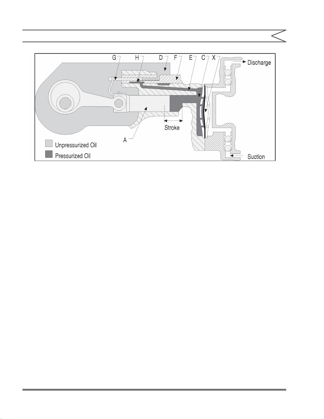
1.5 PRINCIPLE OF OPERATION
Pumping action is developed and controlled by
four basic components as follows (Figures 1 & 2)
1. The pump plunger “A” reciprocates with a
constant stroke length and displaces oil into and
out of the diaphragm chamber “C”.
2. The exible diaphragm “X” is a movable partition
between the plunger oil and liquid being
pumped.
3. An oil bypass circuit from the diaphragm
chamber “C” to the reservoir “D” through
passage “E” bypass port “H” and control spool
valve “F.”
4. A bypass control plunger “G” which moves with
and is directly coupled to the pump plunger to
correlate bypass shut off at port “H” to pump
plunger position.
In operation, as the pump plunger and bypass
control plunger move forward as shown in
Figure 1, the displaced oil is bypassed to the oil
reservoir until the control plunger “G” closes the
8 Installation, Operations & Maintenance Manual
Page 9

SECTION 1 - GENERAL DESCRIPTION
bypass port “H” as shown in Figure 2. Then the
balance of the plunger displacement is imposed on
the exible diaphragm that moves and displaces
the liquid being pumped through the discharge
ball checks.
On the suction stroke, the pump plunger pulls
oil out of the diaphragm cavity, which moves the
exible diaphragm and pulls liquid through the
suction ball checks. When the control plunger
“G” opens the bypass port “H” the balance of the
plunger oil displacement can be supplied from
the reservoir through the bypass passages. The
discharge capacity is adjusted from 0–100%
by rotating the adjustment knob that moves the
control spool valve “F” so that the bypass port “H”
is closed at the desired percentage of the total
plunger stroke. When the control spool valve is
adjusted to 100% capacity, the bypass port will be
positioned so that it is opened at the very end of
the suction stroke. Then on the pressure stroke,
the bypass port is immediately closed so the entire
plunger displacement is imposed upon the exible
diaphragm.
With the control spool valve adjusted for 50%
capacity, the bypass port will be positioned so that
it is opened when the plungers have completed
one-half of the suction stroke. On the next pressure
stroke, the oil displaced by the pump plunger will
be bypassed through the open port to the reservoir
for the rst 50% of the stroke, before the by-pass
port is closed by the control plunger. The remaining
50% of the plunger displacement will then be
imposed on the exible diaphragm so that liquid
is discharged for only 50% of the plunger travel. A
similar analysis would apply for 0% capacity setting
on the control spool valve where all the plunger oil
displacement is bypassed to the reservoir.
1.6 GENERAL SPECIFICATIONS
Figure 1. Pump Operation With By-Pass Port Open
9Installation, Operations & Maintenance Manual
Page 10
SECTION 1 - GENERAL DESCRIPTION
Figure 2. Pump Operation With By-Pass Port Closed
Accuracy
±1% steady state accuracy over 10:1 turndown
Drive
Hydraulic bypass design allows adjustment from 0
to 100% of rated capacity while stopped or running
Liquid End
High performance check valves
Diaphragm
Hydraulically actuated Diaphragm provides 96000
hours of long life in comparison with Mechanically
actuated Diaphragm (15000 to 20000 hours).
Relief Valve
Adjustable internal relief valve
Capacity Control
Micrometer ...............................................standard
Electronic ....................4–20 mA
Pneumatic ....................3–15 psi
Stroke Length
Models mRoy C, D, E, F............. 0.7” (1.78 cm)
Models mRoy K, L, R ...................... 1.5” (3.81 cm)
10 Installation, Operations & Maintenance Manual
Page 11
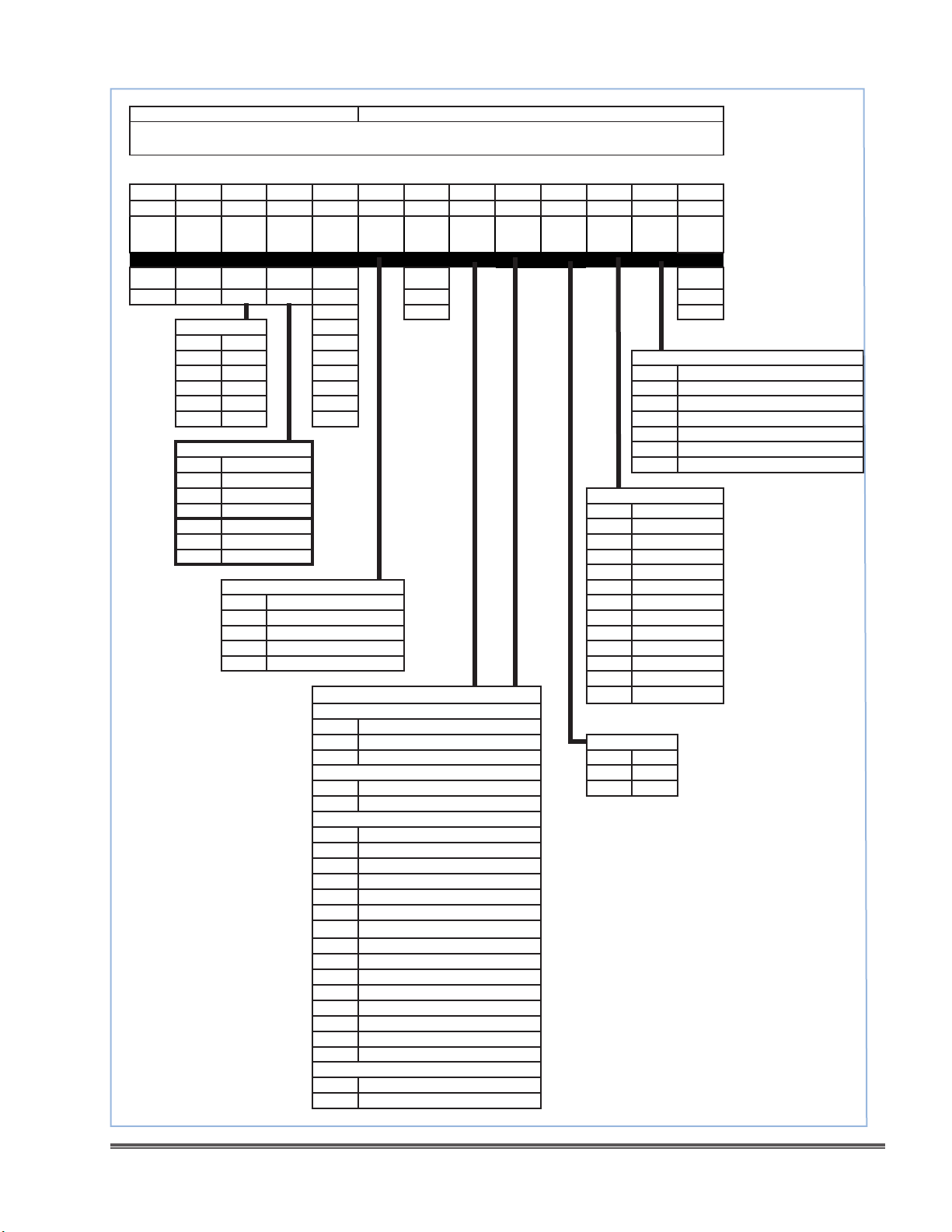
What key features drive product sizing Features that drive every build
Standard mRoy A & B Pump Model Code
MRA 1 1 C 48 A1 A N N V N N N
End Item # Heads Mat ’l Plg Dia
MRA 1 Dup L/R Dup L/R
MRB 2 A-B A-B
10 20 30 40 50 60 70 80 90 100 110 120
Gear
Rao
77 C - CC N
48 A - API Y
Mat’l
1 316L SS 24
2 PVC 19 Diaphragm Rupture Detecon
5 Alloy 20 15 N None
6 Hast C 12.5
7 PVDF 9.5 4 Pressure type w/gauge & NEMA 4 Switch
8 Fluoride 8 5 Pressure type w/gauge & Ex Prf Switch
Plg Dia
C 3/8” (9.5 mm) 9 Pressure type w/pressure transmier
D 7/16” (11.1 mm)
E 5/8” (15.9 mm) Capacity Control
F 1 1/16” (27 mm) N Aluminum (std)
K 19/32” (15.1 mm) S Stainless Steel
L 7/8 “ (22.2 mm) L SS Locking (API)
R 1 7/16” (36.5 mm)
Motor Mount Only - Special motor F ECC Ex Prf 115V
S5 NEMA 56C G ECC Ex Prf 220V
S1 NEMA 143TC/145TC M ECC Mount Only
S7 IEC 71 P Pneumac
S8 IEC 80 3 Rotork NEMA 4 w/ com
S9 IEC 90 4 Rotork XP w/ com
38 M* - META V (VSD)
25
Motor
Motor
mount
Sucon
Conn
Dischrge
Conn
O Ring
Material
Control
Dia
Cap
Rupture
Detect
3
6 Double Dia with intermed uid no probe
7 Double Dia w/ intermed uid & conduct probe
A
ECC NEMA 4 115V
B ECC NEMA 4 220V
C ECC NEMA 4 115V - Asia
Connecons D ECC NEMA 4 220V - Asia
Threaded - metal
P NPT
H BSPP - Horizontal O Ring Opons
V BSPP - Vercal (discharge only) N Standard
Threaded - plasc E EPDM
P NPT T Te ex
4 BSPP
Flanged - Metal
A ANSI 1/2 Class 150 RF Thd
B ANSI 1/2 Class 300 RF Thd
C ANSI 1/2 Class 600 RF Thd
D ANSI 1/2 Class 150 RF Skt wld
E ANSI 1/2 Class 300 RF Skt wld
F ANSI 1/2 Class 600 RF Skt wld
G ANSI 1/2 Class 150 RF/ SF Weld Neck
J ANSI 1/2 Class 300 RF / SF Weld Neck
K ANSI 1/2 Class 600 RF / SF Weld Neck
L ANSI 1/2 Class 1500 RF / SF Weld Neck
M EN 1759-1 DN15 Class150 TYPE B1 / 11
N EN 1092-1 DN15 PN40 TYPE B1 / 11
Q EN 1759-1 DN15 Class300 TYPE B1 / 11
R EN 1759-1 DN15 Class600 TYPE B1 / 11
S EN 1759-1 DN15 Class1500 TYPE B1 / 11
Flanged - Plasc
1 ANSI 1/2 Class 150 RF Thd
2 ANSI 1/2 class 150 Plasc Slvnt wld
Base
Pressure type w/gauge only
Figure 3. Global MRA/MRB Model Code
11Installation, Operations & Maintenance Manual
Page 12

Extended mRoy A & B Opons
Appears along with Common opt code if any value is not “N”
N N N N N N N N
10 20 30 40 50 60 70 80
LE Opon
LE Opons
N None
V High viscosity
S Slurry
D Degas
E Europe source parts
G G7 weed parts
C NACE MR175
Temperature Opons
N Standard, 20F to 190F (-7 to 88C)
1 Low ambient, -40 to 20F (-40 to -7C)
2 High, 190 to 300F (88 to 149C)
3 Temp control jacket
Drive Opons
N Standard
H High sucon pressure
S Sand protect design
M Marine design Component Tests
R Retrot base EMEA N None
Motor Opons 2 PMI and Hydro Combinaon
N No 3 Hydrostac test 1.5 x max rang - head only
Y Yes 4 Hydrostac Test & Cercate
V Variable freq drive 5 Witnessed Hydrostac Test & Cercate
C Motor w/ VFD 6 Dye penetrant for welds only
Lubricaon Opons
N Standard
3
4 Food Grade Oil N Standard RAL 1018
5 High performance synthec A Paint 160 µ RAL 1018
9 Ship without oil B Food Grade Paint - RAL 9010
Low temp non synthec (15 to
Temp
50F) Coang Systems
Less Common Opon Extension
Drive op-
ons
Motor
Opons
Lube
C 250 µ Oshore Paint RAL 1018
D 350 µ Oshore Paint RAL 1018
E C5-M
F ACQPA
G FROSIO
H NORSORK M501
Coang
System
Component
Test
Run Test
Run Test Opons
Code Test Descripon
Standard Production
N
A
B
C
D
E
F
G
H
Tests
Witnessed Standard
Production Tests
API Linearity Test (5
Point Curve)
Witnessed API
Linearity Test
API Repeatabil-
ity Test (10 Point
Curve)
Witnessed API
Repeatability Test
API Test Package 10 point curve, hydro,
Witnessed API Test
Package
Customer Final
Inspection
1 PMI - Weed metallic parts
7 Radiography for welds only
Includes Std. Production
Tests
Includes Std. Production
Tests
Includes Std. Production
& API Linearity Tests
Includes Std. Production
& API Linearity Tests
production test
10 point curve, hydro,
production test wit-
Per visit
Figure 4. Global MRA/MRB Model Code Extra
12 Installation, Operations & Maintenance Manual
Page 13

ROUTINE MAINTENANCE KITS mRoy A & B
mRoy RPM kits for pumps noted above
Part Number Descripon 1 Descripon 2
RPM1001 KIT MRA 316L VITON ORING NPT PLGR CODE C,D,E,F
RPM1002 KIT MRA PVC VITON ORING NPT PLGR CODE C,D
RPM1036 KIT MRA PVC TEFLEX ORING NPT PLGR CODE C,D
RPM1037 KIT MRA PVC VITON ORING NPT PLGR CODE E,F
RPM1038 KIT MRA PVC TEFLEX ORING NPT PLGR CODE E,F
RPM1003 KIT MRA A20 VITON ORING NPT PLGR CODE C,D,E,F
RPM1004 KIT MRA C22 VITON ORING NPT PLGR CODE C,D,E,F
RPM1005 KIT MRA PVDF VITON ORING NPT PLGR CODE C,D
RPM1039 KIT MRA PVDF TEFLEX ORING NPT PLGR CODE E,F
RPM1040 KIT MRA PVDF VITON ORING NPT PLGR CODE C,D
RPM1041 KIT MRA PVDF TEFLEX ORING NPT PLGR CODE E,F
RPM1006 KIT MRA FLOR VITON ORING NPT PLGR CODE C,D
RPM1042 KIT MRA FLOR TEFLEX ORING NPT PLGR CODE C,D
RPM1043 KIT MRA FLOR VITON ORING NPT PLGR CODE E,F
RPM1044 KIT MRA FLOR TEFLEX ORING NPT PLGR CODE E,F
RPM1007 KIT MRA SLURRY VITON ORING NPT PLGR CODE E,F
RPM1008 KIT MRA 316 HV VITON ORING NPT PLGR CODE C,D,E,F
RPM1009 KIT MRA A20 HVVITON ORING NPT PLGR CODE C,D,E,F
RPM1010 KIT MRA 316L EPDM ORING NPT PLGR CODE C,D,E,F
RPM1011 KIT MRA 316L TEFLEX ORING NPT PLGR CODE C,D,E,F
RPM1012 KIT MRA A20 EPDM ORING NPT PLGR CODE C,D,E,F
RPM1013 KIT MRA A20 TEFLEX ORING NPT PLGR CODE C,D,E,F
RPM1014 KIT MRB-K 316L VITON ORING PLGR CODE K
RPM1015 KIT MRB-K A20 VITON ORING PLGR CODE K
RPM1016 KIT MRB-K 316L EPDM ORING PLGR CODE K
RPM1017 KIT MRB-K 316L TEFLEX ORING PLGR CODE K
RPM1018 KIT MRB-K A20 EPDM ORING PLGR CODE K
RPM1019 KIT MRB-K A20 TEFLEX ORING PLGR CODE K
RPM1020 KIT MRB-L/R 316L VITON ORING PLGR CODE L,R
RPM1021 KIT MRB-L/R 316L EPDM ORING PLGR CODE L,R
RPM1022 KIT MRB-L/R 316L TEFLEX ORING PLGR CODE L,R
RPM1023 KIT MRB-L/R A20 VITON ORING PLGR CODE L,R
RPM1024 KIT MRB-L/R A20 EPDM ORING PLGR CODE L,R
RPM1025 KIT MRB-L/R A20 TEFLEX ORING PLGR CODE L,R
RPM1026 KIT MRB-L/R PVC VITON ORING PLGR CODE L,R
RPM1027 KIT MRB-L/R PVC EPDM ORING PLGR CODE L,R
RPM1028 KIT MRB-L/R PVC TEFLEX ORING PLGR CODE L,R
Figure 5. RPM KITS
13Installation, Operations & Maintenance Manual
Page 14
RPM1029 KIT MRB-L/R PVDF VITON ORING PLGR CODE L,R
RPM1030 KIT MRB-L/R PVDF EPDM ORING PLGR CODE L,R
RPM1031 KIT MRB-L/R PVDF TEFLEX ORING PLGR CODE L,R
Figure 5. RPM KITS
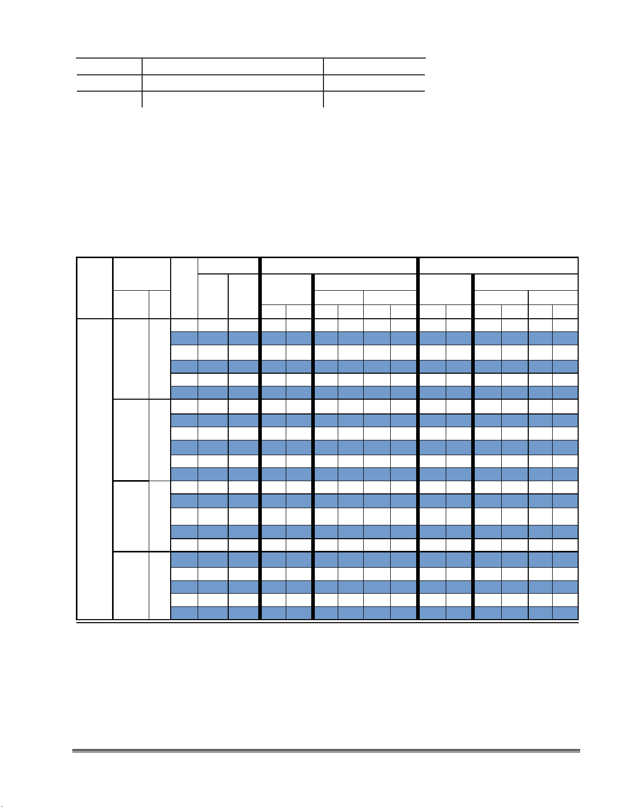
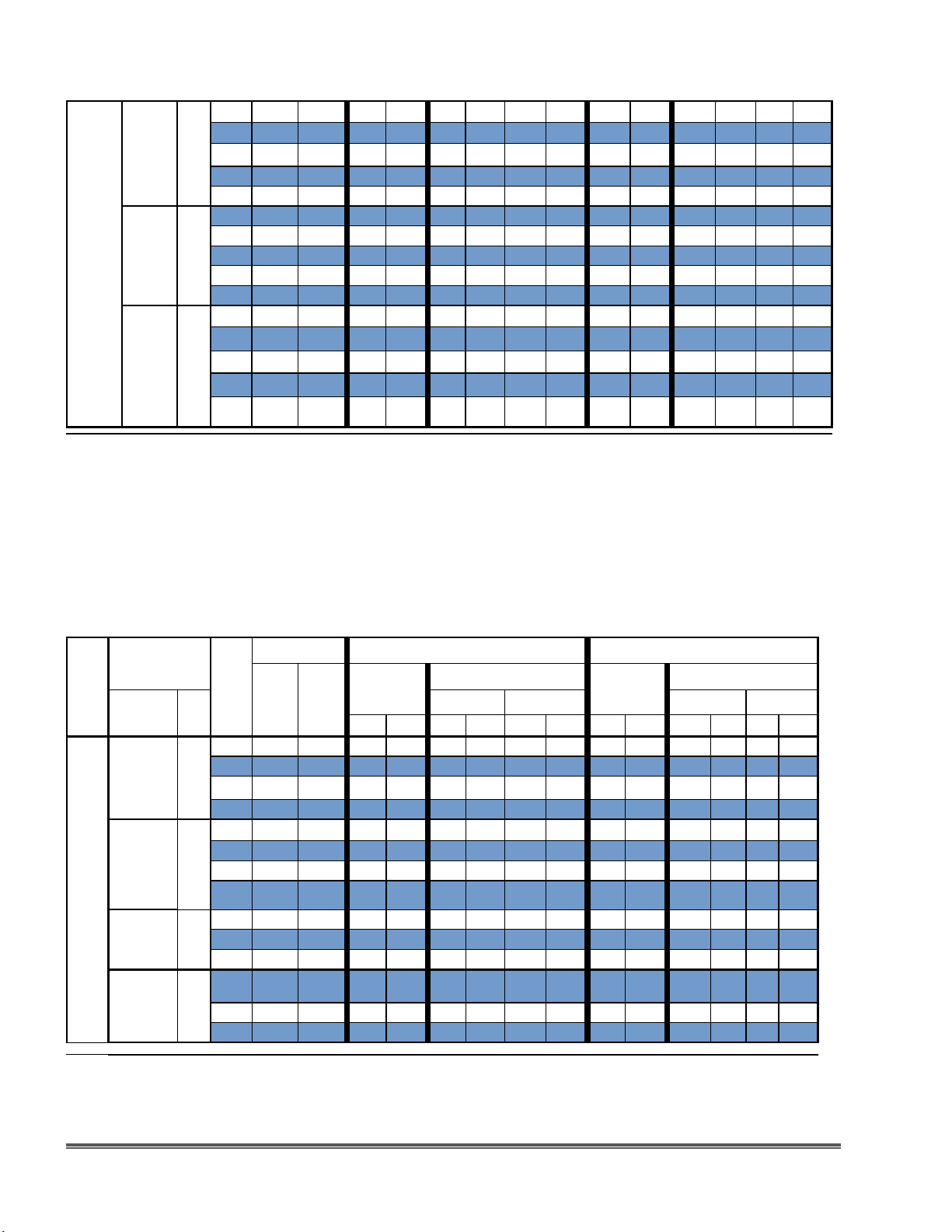
mRoy Series Capacity/Pressure Selection - Metallic Liquid Ends
●Capacies shown are for simplex. Double capacity for duplex
●Actuators, rupture detecon, and high viscosity opons require capacity derang per the table on the next page
●Plasc liquid ends are limied to 150 psi - 10 bar
mRoy
Series
A
Plunger
Diameter Code
3/8”
C
9.5 mm
7/16”
D
11.1 mm
5/8”
E
15.9 mm
1 1/16”
F
27 mm
Strokes/Minute
Gear
Rao
60 hz
1725
RPM
50 hz
1425
RPM
Code
77 23 19 0.36
48 37 30 0.73
24 73 60 1.44
15 117 96 2.32
10 185 152 3.64
8 - 178
77 23 19 0.57
48 37 30 0.8
24 73 60 1.7
15 117 96 2.8
10 185 152 4.4
8 - 178
48 37 30 1.8
24 73 60 3.8
15 117 96 6.2
10 185 152
8 - 178
48 37 30 6.1
24 73 60 12.3
15 117 96 19.4
10 185 152 30.0
8 - 178
Capacity / Pressure @ 60 hz 1725 RPM Capacity / Pressure @ 50 hz 1425 RPM
Rangs at
100 psi/7 bar
Capacity at Max pressure
Capacity Max Pressure Capacity Max Pressure
Rangs at
100 psi/7 bar
Capacity at Max pressure
GPH L/hr GPH L/hr PSI Bar GPH L/hr GPH L/hr PSI Bar
0.20
1.4
0.34
2.8
0.68
5.5
1.09
8.8
1.72
13.8
- - - -
0.4
2.2
0.6
3
1.2
6.4
10.6
16.7
2
3.1
- - - -
1.6
6.8
3.5
14.4
5.7
23.5
9.4 35.6 8.4 31.8
- - - -
5.5
23.1
11.2
46.6
18.1
73.4
29.0
113.6
- - - -
0.8
1.3
2.6
4.1
6.5
1.5
2.3
4.5
7.6
11.7
6.1
13.2
21.6
20.8
42.4
68.5
109.8
2000 137.9
2000 137.9
2000 137.9
2000 137.9
2000 137.9
- -
1800 124.1
1800 124.1
1800 124.1
1800 124.1
1800 124.1
- -
700 48.3
925 63.8
925 63.8
925 63.8
- -
350 24.1
350 24.1
350 24.1
200 13.8
- -
0.30 1.1 0.17 0.6 2000 137.9
0.61 2.3 0.28 1.1 2000 137.9
1.20 4.5 0.57 2.2 2000 137.9
1.93 7.3 0.91 3.4 2000 137.9
3.03 11.5 1.43 5.4 2000 137.9
3.55 13.4 1.67 6.3 2000 137.9
0.48 1.8 0.33 1.2 1800 124.1
0.67 2.5 0.50 1.9 1800 124.1
1.42 5.4 1.00 3.80 1800 124.1
2.33 8.8 1.67 6.30 1800 124.1
3.67 13.9 2.58 9.80 1800 124.1
4.30 16.3 3.02 11.40 1800 124.1
1.50 5.7 1.3 5.0 700 48.3
3.17 12 2.9 11.1 925 63.8
5.17 19.6 4.8 18.0 925 63.8
7.83 29.6 7.0 26.5 925 63.8
9.17 34.7 8.2 31.0 925 63.8
5.08 19.2 4.6 17.3
10.25 38.8 9.3 35.3
16.17 61.2 15.1 57.1
25.00 94.6 24.2 91.5
29.28 110.8 28.3 107.1
350 24.1
350 24.1
350 24.1
200 13.8
200 13.8
Figure 6. mRoy A Metallic Liquid End Capacity Tables
14Installation, Operations & Maintenance Manual
Page 15
38 48
19/32”
15.1 mm
7/8”
B
22.2 mm
1 7/16”
36.5 mm
K
L
R
25 72
19 96
12 144
10 -
38 48
25 72
19 96
12 144
10 -
38 48
25 72
19 96
12 144
120
148 1500
120
148 1000
120
40
60
80
40
60
80
40
60
80
4.7
17.8
7.0
26.5
9.5
13.3
50.3
10.0
37.9
16.0
60.6
21.0
79.5
30.4
115.1
27.0
102.2 21.0 79.5 400
42.0
57.0
215.7 51.0 193 400
85.0
321.7 79.0 299 400
3.3
5.6
7.1
36
11.4
4.7
11.0
16.0
25.6
159 36.0 136.3 400
12.5 1500
21.2 1500
26.9 1500
43.1 1500
17.8 1000
41.6 1000
60.6 1000
96.9 1000
103.4
3.92 14.8 2.8 10.4 1500
103.4
5.83 22.1 4.7 17.7 1500
103.4
7.92 30 5.9 22.4 1500
103.4
11.08 41.9 9.5 36.0 1500
103.4
13.67 51.7 11.72 44.3 1500
69
8.33 31.5 3.9 14.8 1000
69
13.33 50.5 9.2 34.7 1000
69
17.50 66.2 13.3 50.5 1000
69
25.33 95.9 21.3 80.7 1000
69
31.24 118.2 26.31 99.6 1000
27.6
22.50 85.2 17.5 66.2 400
27.6
35.00 132.5 30.0 113.6 400
27.6
47.50 179.8 42.5 160.9 400
27.6
70.83 268.1 65.8 249.2 400
103.4
103.4
103.4
103.4
103.4
69
69
69
69
69
27.6
27.6
27.6
27.6
10 -
148
- - - -
400
27.6
Figure 7. mRoy B Metallic Liquid End Capacity Tables
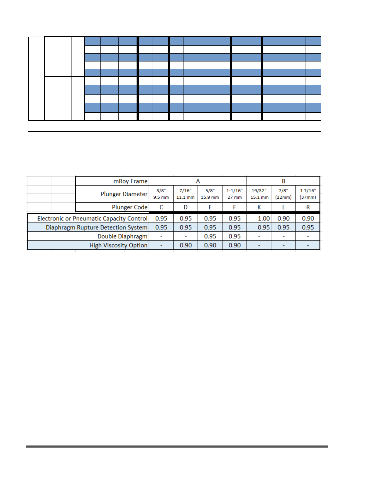
mRoy Series Capacity/Pressure Selection - Plastic Liquid Ends
●Includes PVC, PVDF liquid ends, and liquid ends for Fluoride applicaons
●Capacies shown are for simplex. Double capacity for duplex
●Actuators, rupture detecon, and high viscosity opons require capacity derang per the table on the next page
●Please note that plasc liquid ends are not available for plunger code “K” - mRoy B frame with 19/32” (15.1 mm) plunger.
mRoy
Series
A
Plunger
Diameter Code
3/8”
C
9.5 mm
7/16”
D
11.1 mm
5/8”
E
15.9 mm
Strokes/Minute
Gear
Rao
60 hz
1725
RPM
50 hz
1425
RPM
Code
77 23 19 0.32 1.2 0.28 1.1 150 10.3 0.27 1 0.23 0.9 150 10.3
48 37 30 0.68 2.6 0.62 2.3 150 10.3 0.57 2.2 0.52 2 150 10.3
24 73 60 1.35 5.1 1.30 4.9 150 10.3 1.13 4.3 1.08 4.1 150 10.3
15 117 96 2.20 8.3 2.10 7.9 150 10.3 1.83 6.9 1.75 6.6 150 10.3
77 23 19 0.5 1.9 0.45 1.7 150 10.3 0.42 1.6 0.38 1.4 150 10.3
48 37 30 0.7 2.6 0.65 2.5 150 10.3 0.58 2.2 0.54 2 150 10.3
24 73 60 1.5 5.7 1.4 5.3 150 10.3 1.25 4.7 1.17 4.40 150 10.3
15 117 96 2.5 9.5 2.4 9.1 150 10.3 2.08 7.9 2.00 7.60 150 10.3
48 37 30 1.6 6.1 1.5 5.7 150 10.3 1.33 5 1.3 4.7 150 10.3
24 73 60 3.5 13.2 3.4 12.9 150 10.3 2.92 11.1 2.8 10.7 150 10.3
15 117 96 5.6 21.2 5.5 20.8 150 10.3 4.67 17.7 4.6 17.3 150 10.3
Capacity / Pressure @ 60 hz 1725 RPM Capacity / Pressure @ 50 hz 1425 RPM
Rangs at
100 psi/7 bar
Capacity at Max pressure
Capacity Max Pressure Capacity Max Pressure
GPH L/hr GPH L/hr PSI Bar GPH L/hr GPH L/hr PSI Bar
87.36 330.6 81.19 307.3 400
Rangs at
Capacity at Max pressure
100 psi/7 bar
27.6
1- 1/16”
27 mm
48 37 30 5.7 21.6 5.6 21.2 150 10.3 4.75 18 4.7 17.7 150 10.3
F
24 73 60 11.3 42.8 11.2 42.4 150 10.3 9.42 35.7 9.3 35.3 150 10.3
15 117 96 18.1 68.5 18.0 68.1 150 10.3 15.08 57.1 15.0 56.8 150 10.3
Figure 8. mRoy A Plastic Liquid End Capacity Tables
15 Installation, Operations & Maintenance Manual
Page 16
38 48 40 10.0 37.9 4.7 17.8 150 10.3 8.33 31.5 3.9 14.8 150 10.3
7/8”
22.2 mm
B
1 - 7/16”
36.5 mm
25 72 60 16.0 60.6 11.0 41.6 150 10.3 13.33 50.5 9.2 34.7 150 10.3
L
19 96 80 21.0 79.5 16.0 60.6 150 10.3 17.50 66.2 13.3 50.5 150 10.3
12 144 120 30.4 115.1 25.6 96.9 150 10.3 25.33 95.9 21.3 80.7 150 10.3
10 - 148 150 10.3 31.24 118.2 26.31 99.6 150 10.3
38 48 40 27.0 102.2 21.0 79.5 150 10.3 22.50 85.2 17.5 66.2 150 10.3
25 72 60 42.0 159 36.0 136.3 150 10.3 35.00 132.5 30.0 113.6 150 10.3
R
19 96 80 57.0 215.7 51.0 193 150 10.3 47.50 179.8 42.5 160.9 150 10.3
12 144 120 85.0 321.7 79.0 299 150 10.3 70.83 268.1 65.8 249.2 150 10.3
10 - 148 - - - - 150 10.3 87.36 330.6 81.19 307.3 150 10.3
Figure 9. mRoy B Plastic Liquid End Capacity Tables
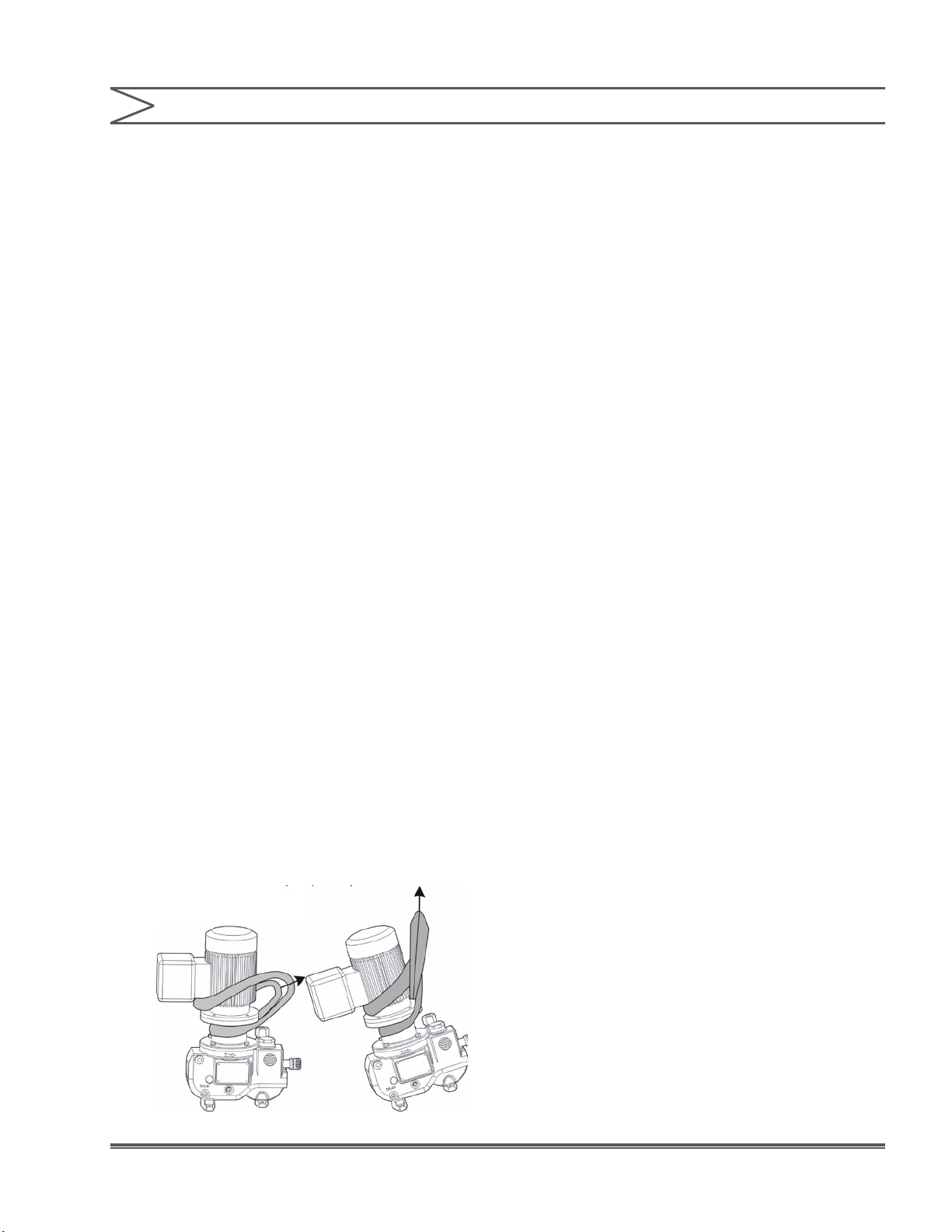
mRoy PUMP FLOW DERATING TABLE
NOTES:
Certain options require that the maximum capacity be derated. Multiply capacities in the
capacity / pressure tables in Figures 7 through 10 by the appropriate factors in the table above.
Figure 11. mRoy Pump (All Models) Capacity Derating Table
16 Installation, Operations & Maintenance Manual
Page 17

SECTION 2 - INSTALLATION
2.1 UNPACKING/INSPECTION
Units are shipped Ex Works and the title passes
to the customer when the carrier signs for receipt
of the unit. In the event that damages occur during
shipment, it is the responsibility of the customer to
notify the carrier immediately and to le a damage
claim. Carefully examine the shipping crate upon
receipt from the carrier to be sure there is no
obvious damage to the contents. Open the crate
carefully so accessory items fastened to the inside
of the crate will not be damaged or lost. Examine
all material inside the crate and check against the
packing list to be sure that all items are accounted
for and intact.
2.2 STORAGE
Short Term Storage (Less than 6 Months)
It is preferable to store the material under a shelter
in its original package to protect it from adverse
weather conditions. In condensing atmospheres,
follow the long term storage procedure.
Long Term Storage (Longer than 6 Months)
The primary consideration in storage of pump
equipment is to prevent corrosion of external and
internal components. This corrosion is caused
by natural circulation of air as temperature of the
surroundings change from day to night, day to day,
and from season to season. It is not practical to
prevent this circulation which carries water vapor
and other corrosive gasses, so it is necessary to
protect internal and external surfaces from their
effects to the greatest extent possible.
When the instructions given in this section are
completed, the equipment is to be stored in a
shelter; protected from direct exposure to weather.
The prepared equipment should be covered with a
plastic sheet or a tarpaulin, but in a manner which
will allow air circulation and prevent capture of
moisture. Equipment should be stored 12 inches
(.304 meters) or more above the ground.
If equipment is to be shipped directly from Milton
Roy into long term storage, contact Milton Roy to
arrange for long term storage preparation.
Pump Drive
1. Remove motor and flood the gearbox
compartment with a high grade lubricating
oil/rust preventative Mobile Oil Corporation
product Mobilarma 524 or approved equivalent.
Fill the compartment completely to minimize air
space. After storage, drain this oil and rell the
equipment with the recommended lubricant for
equipment commissioning.
2. Brush all unpainted metal surfaces with
multipurpose grease NLGI grade 2 or 3 or
approved equivalent. Store these unattached.
Electrical Equipment
1. Motors should be prepared in the manner
prescribed by their manufacturer. If information
is not available, dismount and store motors as
indicated in step 3 below.
2. Dismount electrical equipment (including
motors) from the pump.
3. For all electrical equipment, place packets of
Vapor Phase Corrosion Inhibitor (VPCI) inside of
the enclosure, then place the entire enclosure,
with additional packets, inside a plastic bag.
Seal the bag tightly closed. Contact Milton Roy
Service Department for recommended VPCI
materials.
17 Installation, Operations & Maintenance Manual
Page 18
SECTION 2 - INSTALLATION
2.3 SAFETY PRECAUTIONS
When installing, operating, and maintaining the
mRoy pump, keep safety considerations foremost.
Use proper tools, protective clothing, and eye
protection when working on the equipment and
install the equipment in compliance of NEC,
NEPA and local codes. Follow the instructions in
this manual and take additional safety measures
appropriate to the liquid being pumped. Be
extremely careful in the presence of hazardous
substances (e.g., corrosives, toxics, solvents,
acids, caustics, ammables, etc.).
2.4 PUMP MOUNTING&LIFTING/
LOCATION
The mRoy pump can be mounted on any surface
that is at and level for the support feet. Three
mounting bolt holes are provided in the support feet
for use when the pump is to be rmly anchored to
a base surface (see Figure 14.)
Increased reliability can be expected if pump
locations are avoided which are subjected to high
ambient temperatures above 100°F (38°C) with
poor free-air circulation over the pump assembly.
2.5 OUTDOOR INSTALLATIONS
The mRoy pump is designed as a totally enclosed
unit suitable for installation either indoors or
outdoors. However, for outdoor installations the
pump mounting area should be selected to provide
protection against environmental extremes:
1. Operation with continuous exposure to sunshine
with ambient temperatures above 90°F (32°C),
which would cause higher oil temperatures
and reduce lubricity should be avoided. Good
installation practice would dictate providing
a sun shade over the pump with open sides
to obtain the best air circulation around the
pump.
2. Frequent start-up where the pump has been idle
in an ambient temperature below 30°F (-1°C)
is not recommended. Provide a removable,
insulated enclosure over the pump and mounting
base with provisions for an electrical heater
(100 watt light, heat lamp, heater tape etc.) to
Lifting
Put the sling under the motor terminal box and
under the motor ange. Cross the two ends
of the sling and close the loop (see diagrams).
Before attempting to move it, check that the
entire unit is well balanced.
Note: As soon as the pump is in position, fasten
it down.
18Installation, Operations & Maintenance Manual
Page 19
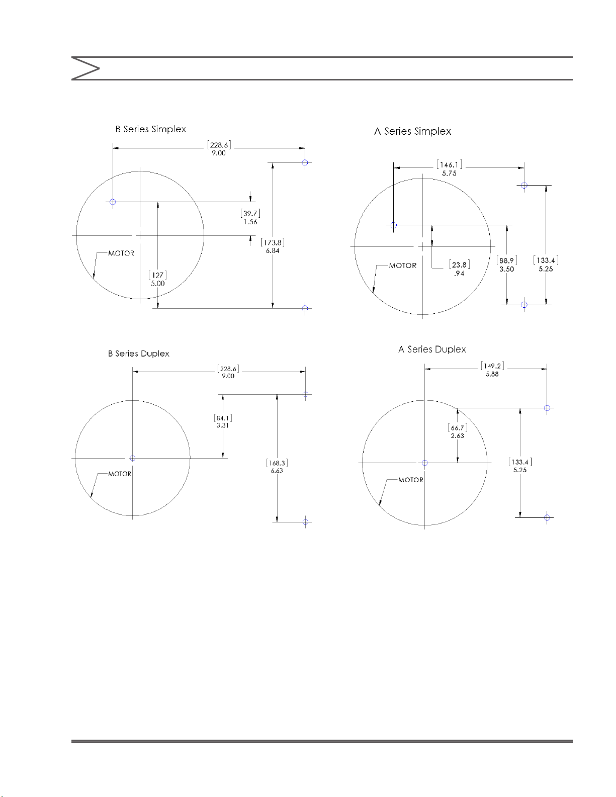
• B Series Hole Size = Dia 0.41” (10.4 mm) • A Series Hole Size = Dia 0.38” (9.6 mm)
Figure 14. Mounting Bolt Holes
19Installation, Operations & Maintenance Manual
Page 20
SECTION 2 - INSTALLATION
maintain the pump oil temperature above 30°F
(-1°C).
2.6 FLANGE MOUNTED MOTORS
If a ange mounted motor option was selected for
the mRoy pump, the customer supplied motor will
need to be mounted to the pump. This is generally
a straight forward procedure. Refer to Figure 17 or
18, as appropriate.
When mounting the motor to a Close Coupled
Flange, the motor mount plate (710) must be
removed from the pump body and bolted to the
motor. The motor/motor mount plate assembly can
then be bolted to the pump.
2.7 ELECTRICAL CONNECTIONS
Check to be sure that the electrical supply
matches the pump motor nameplate electrical
characteristics. Motor rotation must be counter
clockwise when viewed from the top end of the
motor.
ON SINGLE-PHASE
PUMP MOTORS THE
ROTATION WILL BE DETERMINED AT THE
FACTORY AND MUST NOT BE CHANGED. ON
THREE-PHASE PUMP MOTORS THE ROTATION
MUST BE DETERMINED AT THE TIME OF
INSTALLATION AND PRIOR TO START-UP.
OPERATION WITH THE WRONG ROTATION WILL
DAMAGE THE PUMP AND MOTOR AND VOID THE
WARRANTY. SHAFT ROTATION CAN BE
OBSERVED BY REMOVING THE COVER PLATE
OVER THE ELECTRICAL CONNECTIONS.
2.8 MOTORS
Adequate power is provided to the simplex mRoy A
pump by the standard ¼ HP (0.25 Kw) motor. The
motor is normally a totally enclosed non-ventilated,
type, that is mounted on a 56C-face ange or IEC
Frame 71 ange. The gear reducer (worm shaft) ts
onto the standard motor without using a coupling.
On the larger mRoy B (Figures 10-13), the normal
temperature rise for these motors is 50°C above
ambient temperature, and it can be expected
that these motors will appear to operate at higher
temperatures than are normally experienced.
However, there is no cause for worry if the following
precautions are observed:
1. The motor is placed where there is adequate
ventilation and is protected against excessive
radiation from steam pipes and other heat
sources.
2. The overload heater in the starting device should
be correctly sized for motor full load current
rating as shown on the motor data plate.
Note: For a motor that is supplied by the
customer, Milton Roy is not responsible for any
damage resulting from an improper installation
or for a motor that is not suitable for the
selected environment.
2.9 PUMP LUBRICATION
CAREFULLY UNSCREW
TO REMOVE OIL
RESERVOIR CAP. DO NOT APPLY PRESSURE TO
JOG CAP FROM SIDE TO SIDE OR DIP STICK MAY
BREAK.
Oil is supplied for the average installation
(ambient temperature above 50°F (10°C). See
recommendation below for lower temperature.
Fill pump and gear box by slowly pouring the
recommended oil through the air bleed reservoir
opening until the oil level in the reservoir is level
with oil level mark on outside surface of reservoir.
Level can also be checked with dipstick on oil
reservoir cap. Recheck while pump is operating.
DO NOT OVER FILL AS
MOTOR DAMAGE CAN
RESULT.
20 Installation, Operations & Maintenance Manual
Page 21
SECTION 2 - INSTALLATION
NOTE:
Synthetic oils are available that span the entire
temperature range. Contact Milton Roy for
further information.
Recommended Oil
Any equivalent oil is acceptable.
Ambient
Oil Type
AGMA Spec No. 2 EP No. 5 EP
Zurn Oil Co No. EP 35 No. EP 95
ISO Grade 68 220
Nominal Oil Capacity
Oil Type
AGMA Spec No. 2 EP No. 5 EP
Zurn Oil Co
Temp. 15-50 °F (-9-10
Temp. 15-50 °F
(-9-10 °C)
Ambient
°C)
No. EP 35 No. EP 95
Ambient
Temp. Above
50°F(10°C)
Ambient
Temp. Above
50°F(10°C)
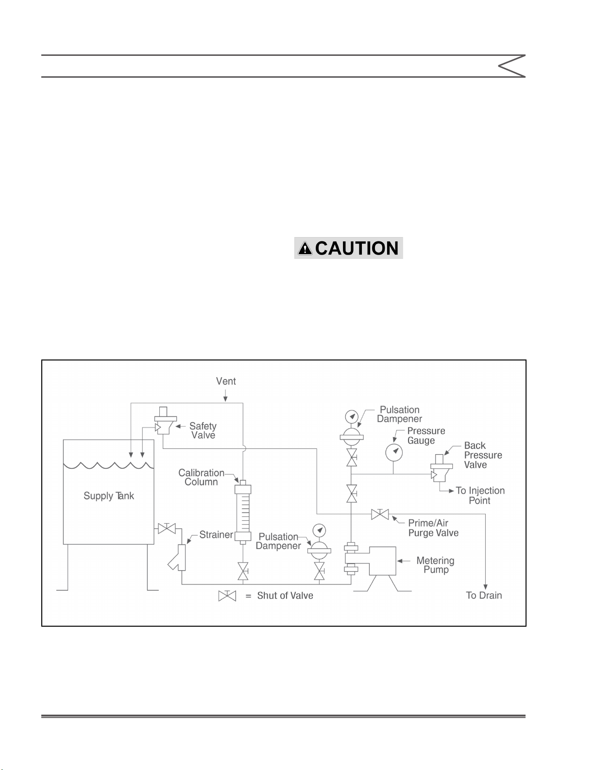
2.10 PIPING
General
Refer to Figure 15 for a diagram of a typical Piping
and Instrumentation Diagram.
Support all piping connections to the pump so
that no stress is placed on pump fittings. In
no case should the piping be sprung to make
the connections to the pump. The suction and
discharge cartridge pipe connections can be
positioned within an arc of approximately 150° to
facilitate piping to pump.
pressured start-up of the nal installation.
Install shut-off valves, with unions on the pump side
of the valves, in the suction and discharge lines to
facilitate servicing.
Use extreme care in piping to plastic liquid end
pumps with rigid pipe such as PVC. If excessive
stresses or vibration is unavoidable, flexible
connections are recommended.
NOTE:
Many pipe joint compounds are not suitable
for use with plastic pipe and, if used, will cause
stress cracking at the connection. Use only
compounds commended for use with plastic
materials.
Suction Piping
The suction piping must be absolutely tight and leak
free. For mRoy pumps on water-like solutions we
recommend that the suction pipe be ¾” minimum
diameter and a maximum of 6 feet (2 meters) long.
The intent is that the piping must be designed to
provide an adequate net positive suction head
(NPSH). Obtain our NPSH Calculation software at
the Milton Roy website (www.miltonroy.com). If
assistance in determining NPSH is needed, contact
the Milton Roy Aftermarket Service department
through the website (www.miltonroy.com)
A ooded suction is recommended for optimum
service life and maintenance-free operation.
However, the mRoy pump can operate with less
than ooded suction if necessary, in accordance
with the following schedule shown in the chart
below.
Flush and blow out all pipelines before connecting
the pump. This eliminates any foreign matter
that might seriously damage the internal working
parts of the liquid end. Install a 20 mesh Y-type
strainer that is sized to remove foreign particles
with minimum pressure drop in the suction line of
the pump. It is also recommended to perform a
leak test of the system with a neutral liquid before
Min. NPSH Max. Li
Model
Number
mRoy A RA 10 10 (3)
mRoy H/T RH or RT 10 10 (3)
mRoy P RP 10 10 (3)
(PSI)
(Ft. (meter) H2O)
(Bar)
21Installation, Operations & Maintenance Manual
Page 22
SECTION 2 - INSTALLATION
further relief valve discussion. (Milton Roy offers a
complete line of back pressure and safety valves).
Refer to “Installation with Suction Lift,” which outlines
limiting conditions if suction lift requirements are
anticipated.
The supply tank should incorporate a low-level
switch to cut off the pump motor before the suction
intake is exposed to air. Otherwise, the pump may
occasionally run dry.
Discharge Piping
The installation of an external Safety Valve is
recommended, since the pump’s internal relief
valve is not intended to protect the piping system.
Refer to “Setting the Relief Valve” in Section 3, for
For satisfactory metering and capacity control,
the discharge pressure at the pump must be
50 PSI (3.5 Bar) minimum for the mRoy A and
70 PSI (4.8 Bar) minimum for the mRoy B.
Therefore, when the pump is to discharge into
an open system, a back pressure device must be
installed in the pump discharge line.
REMOTE HEAD SYSTEMS: DO
NOT INSTALL A BACK
PRESSURE SPRING IN DISCHARGE BALL CHECK CARTRIDGE
OF DIAPHRAGM HEADS WHICH ARE “REMOTE MOUNTED”
(NOT ATTACHED TO THE MAIN HOUSING). A SEPARATE
BACK PRESSURE VALVE MUST BE INSTALLED IN THE
Figure 15. Typical Piping and Instrumentation Diagram
22 Installation, Operations & Maintenance Manual
Page 23

SECTION 2 - INSTALLATION
2.11 OPERATION WITH SUCTION LIFT
It is desirable that the mRoy pump operate
with a ooded suction; however, operation with
net positive suction head (NPSH) less than
atmospheric pressure is possible.
NPSH is the head available, above the vapor
pressure of the liquid being pumped, to feed the
liquid into the pump suction port. NPSH minimum
is the head below which the pump cavitates.
Both values are calculated at the suction port of the
pump. In controlled volume pump applications, two
conditions must be considered in the selection of a
pump to meet the NPSH minimum requirements:
1. At the start of the suction stroke, the liquid in the
suction line has no velocity and NPSH minimum
depends on the force necessary to accelerate
the liquid in the suction pipeline.
2. At the peak of the suction stroke there is
no acceleration factor and NPSH minimum
depends on friction losses as calculated from
standard ow equations. With all viscous liquids
and in pilot plants and other places where
unusual numbers of fittings and valves are
used, the second condition that includes friction
losses should be considered. For water-like
liquids, the rst condition will dene the limiting
conguration.
For Static NPSH (Condition 1)
Available NPSH = Pa + Ph – Pv (must be equal
to or greater than minimum NPSH as listed under
Installation Instructions).
Required NPSH min = Sp. Gr. (0.0925) LpD
For Dynamic NPSH (Condition 2)
Available NPSH = Pa ± Ph – Pf Le (must be equal
to or greater than minimum NPSH as listed under
Installation Instructions).
D = Plunger Diameter (inches)
Dp = Pipe Diameter (inches)
Lp = Actual Length of suction pipe (feet)
Le = Equivalent length of suction pipe including
allowance for ttings (feet)
Pa = Ambient pressure above liquid (PSI)
Ph = Head of liquid column above (+) or below (–)
center line of plunger (PSI) equals Head in feet
x (0.435) (Sp.Gr.)
Pv = Vapor pressure of liquid (PSI)
Pf = Friction loss per foot of pipe calculated from
Reynold Number evaluation (PSI) (Use 3.2
times average velocity for calculating friction
losses when referring to a standard pipe losses
table)
Minimum NPSH = Minimum hydraulic pressure
at plunger (listed under Installation Instructions).
When operating the pump with a NPSH of less
than atmospheric pressure (negative suction head
or suction lift), special attention should be given to
keep the suction line strainer clean and prevent
other system conditions that might inadvertently
decrease the NPSH available.
NOTE:
Obtain our NPSH calculation software at
the Milton Roy website (miltonroy.com). If
assistance in determining NPSH is needed,
contact the Milton Roy Aftermarket Service
Department.
Dp2
23Installation, Operations & Maintenance Manual
Page 24

SECTION 3 - OPERATION
3.1 INITIAL START-UP
Before initial start up of the pump, check the
following:
FAILURE TO CHECK
TORQUE ON NON
METALLIC HEAD BOLTS PRIOR TO STARTUP AND
AFTER ONE WEEK OF OPERATION MAY EXPOSE
OPERATING PERSONNEL TO HAZARDOUS
LIQUIDS.
1. Check the torque on all non-metallic head bolts
prior to startup. After one week of operation,
reduce torque on all nonmetallic head bolts.
Torque the head assembly screws in a crosswise
pattern (Figure 16) as follows:
a) mRoy Model A Plastic Heads: 60–70 in. lbs.
(7-8 N-m) bolting torque.
b) mRoy Model B Plastic Heads:75–85 in. lbs.
(8.5-9.6 N-m) bolting torque, tie down nuts
25 in. lbs. (3 N-m).
2. Check the oil level in air bleed ller reservoir up
to or slightly above the indicated oil level.
3. Set the capacity control knob to approximately
30- 40% of maximum capacity.
is recommended to collect this uid to safe
drain
point during this operation.
- First turn the pump ON
- Place the micrometer on the 50% position, for 10 minutes.
- Untighten the bleeder valve (360) by
around 1/4 turn located on the liquid end.
Thus, the air trapped in the suction piping and the pump head can escape via the
drain. Wait until the liquid comes up to the
evacuation level of this drain. Let it ow for a
few seconds in order to degas it completely,
then retighten the drain plug.
On initial start up with 0% capacity, run
the pump for 10–20 seconds, then stop for
20–30 seconds. Repeat a few times in or-
der to ll the diaphragm oil cavity. Check for
proper motor rotation as described in general
installation instructions. During these short
runs listen for any abnormal motor or crank
noises, and if present, refer to Section 5,
Troubleshooting.
4. Make certain that the suction line, liquid end
and discharge cartridge are lled with water or
system liquid.
5. Relieve all back pressure in the discharge line
and pump hydraulic system to allow air to purge.
Reduce pressure on the oil relief valve until air
is purged. Refer to “Start-Up after the Suction
System has Run Dry” section.
6. If practical, install a temporary discharge line
piped back to the suction tank incorporating
a 100 PSI (7 Bar) relief valve to facilitate
establishing performance during rst hours of
operation.
Priming
In order to prime the pump, it is necessary to
purge the liquid end (to release air) by
the bleeder valve (360). For toxic liquids, it
24 Installation, Operations & Maintenance Manual
Run pump for 1/2 to 1-1/2 hours to warm up oil.
Check discharge line for indication of ow.
Increase capacity adjustment setting to 100% of
capacity and operate for 10–20 minutes.
KNOB IN EXCESS OF 100% BECAUSE ERRATIC
OR REDUCED METERING WILL DEVELOP.
Reduce capacity adjustment setting to 30–40%
of maximum capacity and operate for several
minutes, then increase capacity adjustment back
to 100% for approximately 10 minutes. Repeat
several times to insure that the air is bled from
the pump displacement chamber and the liquid
end. (As a general rule, to bleed air or vapor from
the pump oil displacement chamber reduce the
capacity adjustment to the 20 to 40% range, and
to bleed air or vapor from the liquid end increase
DO NOT SET THE
CAPACITY ADJUSTMENT
Page 25

SECTION 3 - OPERATION
capacity to 100%, or if possible reduce the
discharge pressure to atmospheric pressure for
30 seconds to one minute).
The pump is now ready for calibration. Calculate
what the desired capacity as a percentage of
either the maximum capacity rating on the pump
data plate, or the nominal capacity at the required
system pressure. Each pump is tested at the
factory to conrm that the performance meets
these capacity-pressure requirements (tested
with water). Milton Roy offers a complete line of
calibration columns for calibrating the pump.
Start-Up after the Suction System has Run Dry
In applications where the suction tank does not
have a low level cutoff interconnected into the
pump motor circuit, the pump may occasionally run
dry. This should be avoided to ensure full integrity of
the diaphragm. Running the pump dry occasionally
for no longer than 2 minutes will not harm the
diaphragm or the pump. However, when the pump
is repeatedly allowed to run dry, especially for long
periods of time, the diaphragm is fatigued and could
fail before the next scheduled replacement.
Before restarting a pump that has run dry,
provisions should be made for lling the liquid
end with liquid by opening the discharge line to
atmospheric pressure to either rell liquid end
with ooded suction pressure or start pump with
open discharge and run for a short period of time
(up to 2 minutes) that will ‘prime’ the liquid end if
the ball checks are wet. If these steps fail, remove
the discharge cartridge and ll liquid end with
liquid through the top discharge opening in the
head. After establishing ow, return to the regular
discharge system conguration.
3.2 RESETTING THE RELIEF VALVE
DESCRIPTION
The mRoy pump incorporates an internal relief
valve that is preset at the factory to relieve
when the hydraulic liquid pressure exceeds
125 PSI (8.6 Bar). This setting can be readjusted
as required up to 15% above the maximum rated
pressure of the pump. Resetting the internal relief
valve will change the potential discharge pressure
of the pump.
Refer Figure 18 for a pictorial description of the
mechanism.
Examination of these figures will reveal a
small passage connecting the oil side of the
diaphragm head cavity with the oil reservoir
(See Figures 1 & 2). This passage is stopped off by
a poppet that is held in place by a spring secured
by a set screw. A plastic screw plug keeps the
adjusting threads free of dirt.
In operation, the spring-loaded poppet is held
against the seat in the housing until the pressure
in the oil side of the diaphragm cavity exceeds
the pressure for which the valve has been set.
When this occurs, the poppet is forced off its seat,
permitting the oil to ow from the diaphragm cavity
through the mechanical passage to an opening
(Figure 17) in the side of the oil reservoir. The
resilient material of the poppet permits the relief
valve to actuate without erosion of the poppet or
seat surface.
25Installation, Operations & Maintenance Manual
Page 26

SECTION 3 - OPERATION
Relief Valve Setting
The Pump must be at operational pressure and
95% capacity setting.
1. Remove yellow plastic plug located at top of
pump next to the oil ll hole.
2. Using a 3/16” hex. key (mRoy A), or a 5/16”
hex. key (mRoy B) as required for the different
models, turn the adjusting screw clockwise to
increase cracking pressure until pump ceases
to bypass through the relief valve at the desired
working pressure. When relieving has stopped,
adjust the screw clockwise up to one full turn
beyond this point to set a reasonable buffer zone
between operating pressure and relief pressure.
To determine if relieving is taking place, insert
your index gure into the oil reservoir opening
and place it against the bypass opening
(Figure 17) where the oil pulse from the relief
valve can be determined.
FOR SAFETY REASONS, A
CHECK VALVE IS
RECOMMENDED FOR USE IN THE DISCHARGE LINE NEAR
THE POINT WHERE THE LINE ENTERS A HIGH PRESSURE
PROCESS VESSEL.
3.3 OPERATION
The mRoy pump is designed for reliable, unassisted
operation. During normal operation, a periodic
check of the pump is recommended every 24 or
48 hours to visually conrm satisfactory operation:
1. Make sure the oil level in the air bleed ller
reservoir is above the oil level mark.
2. Inspect the pump liquid end for indication of
leakage or seepage.
If anything seems to be abnormal, refer to Section
4, Maintenance.
3. Reinstall the plastic yellow plug
NOTE:
No moving parts are present in the oil reservoir
in this location.
WHEN OPERATING WITH
RELIEF VALVES, ESPECIALLY
ON PUMPS WITH LARGE PLUNGER SIZE, OIL MAY BE EJECTED
AT HIGH VELOCITY FROM THE BYPASS PORT. NORMAL
PRECAUTION SHOULD BE OBSERVED TO PREVENT THIS
FROM SPLASHING THE SURROUNDING AREA.
NOTE:
This relief is intended primarily for pump
protection in the event that the discharge or
suction system is blocked while the pump is in
operation. It is a good practice to install a highgrade chemical type relief valve in the pump
discharge line as close to the pump as possible,
and always between the pump and any shut-off
valve. Pipe the outlet of the system relief valve
back to the suction tank, with the open end of
the pipe visible at all times. In this way, relief
valve leakage may be easily detected.
26 Installation, Operations & Maintenance Manual
Page 27

SECTION 4 - MAINTENANCE
4.1 SPARE PARTS
To avoid excessive downtime in the event of a parts
malfunction, the spare parts shown below should
be maintained in your stores to support each mRoy
pump. For your convenience, these parts can be
purchased either separately or packaged in the
form of Routine Preventive Maintenance (RPM)
Kits. RPM kit numbers are listed in Section 1,
Figure 7 (mRoy A) & Figure 12 (mRoy B).
Double quantities required for duplex pumps. Two
diaphragms are required for double diaphragm
simplex liquid ends; four are required for double
diaphragm duplex liquid ends.
4.2 RPM KIT COMPONENTS
mRoy A Metallic Liquid End
1 Relief Valve Poppet
1 Suction Check Valve
1 Discharge Check Valve Diaphragm(s) of various
sizes
2 Check Valve O-Ring
2 Split Ring
1 Ball (used on “V” high viscosity option only)
mRoy A Plastic Liquid End
1 Relief Valve Poppet
1 Suction Check Valve
1 Discharge Check Valve Diaphragm(s) of various
sizes
2 Check Valve Seals
1 Square Ring
2 Tube Coupling Nut (used on tube connection
checks only)
mRoy B Plastic Liquid End
1 Relief Valve Poppet
1 Suction Check Valve
1 Discharge Check Valve
1 Diaphragm
3 Check Valve O-ring
Parts Orders Must Include The Following
Information:
1. Quantity required (in this manual)
2. Part number (in this manual)
3. Part description (in this manual)
4. Pump model no. (on pump nameplate)
5. Pump product code (on pump nameplate)
6. Pump serial no. (on pump nameplate)
Always include the serial number, product code,
and model number in all correspondence regarding
the unit.
4.3 RETURNING UNITS TO THE FACTORY
Pumps will not be accepted for repair without a
Return Material Authorization Form, available
from the Aftermarket Department or at the
website (www.miltonroy.com). Process liquid
must be ushed from the pump liquid end, and oil
should be drained from the pump housing before
the pump is shipped. Label the unit clearly to
indicate the liquid being pumped.
NOTE:
Federal law prohibits handling of equipment that
is not accompanied by an OSHA Safety Data
Sheet (SDS). A completed SDS must be packed
in the shipping crate with any pump returned to
the factory. These safety precautions will aid
the troubleshooting and repair procedure and
preclude serious injury to repair personnel from
hazardous residue in the pump liquid end.
All inquiries or parts orders should be addressed
to your local Milton Roy representative.
Representatives can be found on our website
(www.miltonroy.com).
27Installation, Operations & Maintenance Manual
Page 28

SECTION 4 - MAINTENANCE
BEFORE CARRYING OUT ANY
SERVICING OPERATION ON
THE METERING UNIT OR PIPES, DISCONNECT ELECTRICAL
POWER FROM THE PUMP. TAKE THE NECESSARY STEPS TO
ENSURE THAT ANY HARMFUL LIQUID IN THE PUMP OR PIPING
SYSTEM CANNOT ESCAPE OR COME INTO CONTACT WITH
PERSONNEL. SUITABLE PROTECTIVE EQUIPMENT MUST BE
PROVIDED. CHECK THAT THERE IS NO PRESSURE BEFORE
PROCEEDING WITH DISMANTLING.
4.4 ROUTINE MAINTENANCE
The mRoy pump is designed for reliable service
with a minimum amount of maintenance required.
Part of regular maintenance includes:
• Clean the pump regularly to prevent dust or liquid
build-up.
• Check for leaks regularly.
• Check oil levels regularly to prevent pump
damage or overheating.
Yearly replacement of check valves, diaphragm,
and relief valve poppet is recommended. For
convenience, these parts are available in a Routine
Preventative Maintenance (RPM) Kit from your
local representative. RPM kit numbers are listed in
Section 1, Figure 7 (mRoy A) & Figure 12 (mRoy B).
valves are replaced on an annual basis. If highly
corrosive material (acids, slurries, etc.) is being
pumped, some applications may require more
frequent replacement.
In general, poor or reduced pump performance
indicates that the check valves need to be replaced
(refer to Section 5, Troubleshooting).
Complete instructions for replacing worn check
valves are given in the “Corrective Maintenance”
section.
The mRoy check valves are complete assemblies
manufactured at the factory and should not be
disassembled in the eld.
To determine if the check valves need replacement,
with the pump off and pressure removed from
system unscrew the check valve from the liquid end
and look through the hole in the check valve seat.
The ball should appear perfectly round and free of
pits, mars, or scratches. If the ball and/or seat is
excessively damaged, the replacement schedule
should be shortened accordingly. If the ball and
seat are both in good condition, the replacement
schedule can be lengthened.
4.7 DIAPHRAGM(S)
4.5 SEMI ANNUAL OIL CHANGE
The oil in the main housing should be drained twice
a year, using the drain plug provided, and new oil
installed. This can usually be scheduled to coincide
with the change from winter to summer grade
oil and vice versa. Refer to “Pump Lubricants”
in Section 2, Installation, for information on
recommended oil and oil capacity.
The mRoy PTFE diaphragm is extremely durable
and often lasts for many years. As a preventative
measure, Milton Roy recommends that the mRoy
diaphragm be replaced yearly to coincide with
check valve replacement. Also whenever the head
is removed freeing the diaphragm the diaphragm
must be replaced. Refer to the instructions in the
“Corrective Maintenance” section for diaphragm
replacement.
NOTE:
When adding oil, pour in a thin, slow stream
to avoid overow, then check level.
4.6 CHECK VALVE CARTRIDGES
Milton Roy Company recommends that the check
28 Installation, Operations & Maintenance Manual
Page 29

SECTION 4 - MAINTENANCE
4.8 RELIEF VALVE POPPET
Milton Roy recommends that the relief valve
poppet be replaced yearly during preventative
maintenance. This can usually be timed to
coincide with check valve replacement. Refer to
the instructions in the “Corrective Maintenance”
section.
4.9 CORRECTIVE MAINTENANCE
4.9.1 Check Valve Cartridge Replacement
With the exception of the mRoy A and L plastic
versions, mRoy suction and discharge check valve
cartridges are precision machined and assembled
at the factory. Do not attempt to disassemble
these cartridges. If they become inoperative, ush
them with Safety Solvent, wash them with warm
detergent and blow them out with compressed air
to remove any foreign matter. (Refer step 4, from
topic section 4.9.1.1). If this treatment does not
eliminate the trouble, the cartridge assembly should
be replaced. mRoy A plastic suction and discharge
check valve cartridges may be disassembled for
cleaning or parts replacement.
4.9.1.1 Metallic Liquid Ends
(Figures 19, 20, 21 & 24)
Disassembly
1. The check valve cartridge assemblies use
a SAE straight thread with an O-ring seal to
facilitate port alignment with the connecting
pipes. To remove the cartridge from the liquid
end, rst loosen the lock nut (520) one or two
threads then unscrew the cartridge.
2. Remove and discard the O-ring (540) and spiral
back-up ring (530).
3. On model MRA High Viscosity pumps only, the
ball in the suction port of the liquid end is not
sealed inside the suction check valve. This ball
should fall out easily when the suction check
valve is removed.
4. Carefully clean any parts to be reused. If any
chemicals are used in the cleaning process,
ensure that they are approved with the process
liquid.
Reassembly
1. To install the cartridge, position the lock nut
(520) toward the shoulder of the cartridge so that
the recess on the face of the lock nut is adjacent
to the O-ring (540) land (thread undercut) in the
cartridge.
2. Make certain the spiral back-up ring (530)
is coiled in a counterclockwise helix (this is
opposite the direction normally employed by
suppliers of these rings. Fit the spiral back-up
ring (530) in the lock nut (520) recess. Push
it rmly down in the recess as completely as
possible.
3. Install a new O-ring (540) against the spiral
back-up ring (530).
NOTE:
To assure a tight, leak free seal, new O-rings
and spiral back-up rings should be used each
time the check valves are disassembled.
4. On model mRoy “V’ option pumps only (Figure
19), the separate ball (570) needs to be balanced
on the end of the suction check valve cartridge
so that it will be held in place in the suction port
by the check valve when it is screwed in.
5. Screw the cartridge assembly into the liquid end
until the O-ring band is approximately level with
the top of the spot face in the liquid end, then
screw it in one (1) additional turn plus a partial
turn as required to align the pipe thread port
with connecting pipe.
29Installation, Operations & Maintenance Manual
Page 30

SECTION 4 - MAINTENANCE
SUCTION AND CHECK VALVE
CARTRIDGES ARE NOT
IDENTICAL. BE SURE THAT THE CORRECT CARTRIDGE IS
BEING SCREWED INTO THE PROPER PORT. (DISCHARGE
CARTRIDGES HAVE HEXAGONAL CAP ON THE TOP; SUCTION
CARTRIDGES DO NOT.) IF CHECK VALVE CARTRIDGES ARE
INSTALLED INTO THE WRONG PORT, ONE OF THE FOLLOWING
WILL OCCUR: (A) IMMEDIATE SEVERE DAMAGE TO PUMP
MECHANISM, (B) NO PUMPING, (C) REVERSE PUMPING
ACTION (FROM DISCHARGE LINE INTO SUCTION LINE).
6. After completing pipe connection, tighten lock
nut (520) securely against spot face so that
O-ring (540) is trapped in chamfer of liquid end
thread. Make sure that the spiral back-up ring
(530) is completely contained in its recess and
not extending to the outside.
4.9.1.2 mRoy A Plastic, Current Design
(Figure 19)
Disassembly
1. Unscrew the check valve assembly from the
pump liquid end.
2. Both the suction and discharge check valves
may be disassembled in the same way. While
carefully holding the body use a 5/16” rod to
push out the internal parts. Do not damage the
sealing face (opposite the threaded end) on the
valve body. It is essential to reinstall the ball
guides and ball stop in the proper direction, so
take note during disassembly and follow the
assembly drawing.
3. Carefully clean any parts to be reused. If any
chemicals are used in the cleaning process,
ensure that they are approved with the process
liquid.
Reassembly
NOTE:
To assure a tight, leak free seal, new seals and
O-rings should be used each time the check
valves are disassembled.
1. Lightly coat the O-rings on the ball guides
with mineral oil or other food grade lubricant
(Refer step 3, from topic section 4.9.1.2). It is
essential to reinstall the ball guides and ball
stop in the proper direction. Remember the ball
always lifts off the seat in the direction of liquid
ow. The ball stop is used to retain the last ball
check on the suction cartridge.
2. Remove the old valve-to-head seal (435) from
the head and install a new seal. A fracture of
the diaphragm head may result from installing
the check valve against two seals or excessive
tightening. The groove in the seal is to be
oriented against the check valve body.
4.9.1.3 mRoy B Plastic Liquid End (Figure 24)
Disassembly
1. The mRoy B plastic check valves are held in
place by two long bolts (521) that extend through
the diaphragm head. Unscrew the nuts (519) to
remove the check valves from the liquid end.
Use caution when doing so, as the suction check
valve and compression plate (518) will fall off
when the bolt is removed.
2. Remove and discard the check valve O-rings
(540).
3. Carefully clean any parts to be reused. If any
chemicals are used in the cleaning process,
ensure that they are approved with the process
liquid.
Reassembly
NOTE:
To assure a tight, leak free seal, new O-rings
should be used each time the check valves are
disassembled.
1. The discharge check valve consists of two
separate pieces that are shipped held together
30 Installation, Operations & Maintenance Manual
Page 31

SECTION 4 - MAINTENANCE
with masking tape. Leaving the masking tape
in place during assembly will make the process
easier. These parts already have an O-ring in
place between them.
2. Drop a new O-ring (540) into position in the
discharge port of the liquid end. Slip the entire
discharge cartridge (still held together with
masking tape) into the discharge port (only one
end will t in).
3. Screw a nut (521) two or three turns (just enough
to hold) on one end of each through bolt. Slide
the compression plate over the discharge
cartridge (517). Slip the bolts (521) through the
holes in the compression plate and diaphragm
head so that they fall through and hang out the
bottom.
4. Fit a new O-ring (540) into position on the top
of the suction cartridge.
5. Insert the suction cartridge and O-ring up into
the suction port of the liquid end. Position the
other compression plate (518) under the suction
check valve by sliding it up on the bolts. Screw
on the two remaining nuts (519). The suction
check valve should now be held in place in the
liquid end. Tighten the nuts on the through bolts
rmly. Do not over-tighten or plastic ttings may
be damaged.
4.9.2 Relief Valve Poppet Replacement
(Figure 18)
If the pump is allowed to operate for long periods
with the relief valve relieving pressure, there is a
possibility that the poppet will wear, causing erratic
ow and discharge pressure. If this occurs, the relief
valve poppet should be replaced. Even if excessive
wear has not occurred, it is still recommended that
the poppet be replaced on a yearly basis.
2. Unscrew and remove the relief valve adjustment
screw (50).
3. Remove the relief valve spring (40). A pair of
tweezers may be required to remove the spring
from the relief valve port.
4. Remove the relief valve poppet (30) with a
tweezer or by “jogging” the motor, causing oil to
ow up through the relief port to oat the poppet
up and out of the threaded hole.
Reassembly
1. Temporarily secure a new poppet (30) into the
end of the spring (40) with thick grease. Drop
this assembly into place in the relief valve
port.
2. Install the relief valve adjustment screw (50) until
the spring (40) is lightly compressed. Follow the
instructions for resetting the relief valve given in
Section 3, Operation.
4.9.3 Diaphragm replacement (Figure 19-26)
The mRoy A & B models have different assembly
depending on whether they have leak detection.
Be sure to refer to the appropriate Figure (19-26)
when replacing the diaphragm(s).
Disassembly
1. Remove the eight (8) bolts (350 or 355) from
the diaphragm head (330), depending on the
model.
2. Remove the diaphragm (290).
3. Remove the contour plate(s) (282).
4. If servicing a pump with a square ring (260),
remove and discard the square ring.
5. If servicing a double diaphragm style pump,
remove the intermediate chamber and square
head plated pipe.
Disassembly
1. Unscrew and remove the relief valve screw plug
(1350).
6. Carefully clean any parts to be reused. If any
chemicals are used in the cleaning process,
ensure that they are approved with the process
liquid and hydraulic oil.
31Installation, Operations & Maintenance Manual
Page 32

SECTION 4 - MAINTENANCE
Reassembly
1. Place pump on its side with diaphragm cavity
facing up.
2. Install contour plate(s) (282) into position in
the housing and/or diaphragm head (330), as
appropriate.
3. Carefully center diaphragm (290) in the shallow
recess in the housing.
4. If servicing a double diaphragm style pump,
position the intermediate chamber and square
head plated pipe over the diaphragm. Fit a
second new square ring (260) (if required) into
position in the recessed square ring groove.
Carefully center the second diaphragm (290) in
the shallow recess in the intermediate ring.
5. Retain diaphragm with thin, at blade 1/2” to 1”
(12.7 mm to 25.4) mm wide.
6. Carefully position the diaphragm head and
contour plate (this diaphragm head side contour
plate is not used on some models) in place,
aligning bolts holes. Remove blade and torque
bolts as follows (See Figure 16):
a. mRoy Model A Metal Heads: 265–275 in.
lbs. (30-31 N-m) bolting torque (grade 5 or
stronger bolts)
b. mRoy Model A Plastic Heads: 60–70 in. lbs.
(7-8 N-m) bolting torque
c. mRoy Model B Metal Heads: 340-360 in lbs.
(38-41 N-m) bolting torque
d. mRoy Model B Plastic Heads: 75–85 in. lbs.
(8.5-9.6 N-m) bolting torque tie down nuts
25 in. lbs. (3 N-m).
Procedures for complete disassembly of the mRoy
pump are listed below. Some steps can be omitted
depending on which part is replaced.
4.9.4 Motor and Worm Replacement
(Figures 17 & 18)
Be certain that the motor is disconnected before it
is removed in order to replace or inspect the motor
or the gears.
Disassembly
1. Remove oil drain plug and drain oil.
2. Remove the screws that attach the motor to the
pump.
3. On plate mounted units, remove motor; the
gear shaft may come out as well. If the motor
separates from the worm shaft (640), use care
not to lose the shaft key and coil spring.
4. Remove worm assembly (120).
5. On units with API motor mount adapters;
removal of the motor and adapter together will
also lift the worm gear shaft from the pump.
Reassembly
1. Reinstall by reversing steps 1 through 5 or follow
the “motor conversion” directions.
Note: Apply sealant all around the edge and around
the 4 bolt holes of the face of the motor mount as
shown. Before you assemble the motor mount on
the pump make sure you have sealant all around
the ange and covering the 4 holes.
4.9.5 Control Spool O-Rings Replacement
(Figure 17, 19 & 20)
Occasionally, the control spool O-rings may need
to be replaced. Replacement is usually indicated if
pump delivers less rated ow than expected.
Disassembly
1. Remove E-ring (220).
2. Unscrew and remove capacity control knob
(210).
3. Remove screw (180) in threaded sleeve (170)
(capacity control).
4. Remove diaphragm head (330), diaphragm
(290), contour plate (280 & 285), and motor and
motor mount.
32 Installation, Operations & Maintenance Manual
Page 33

5. Remove control spool (160) from bore.
6. For mRoy A pumps, fabricate a tool by inserting
a 3/16” diameter x 4-in. long soft plastic
(e.g. Nylon) solid rod into the 3/16” hole and
shaping the end with a 7/16” reamer inserted
into the control spool bore. For the mRoy B
pumps, a tool is not required.
CAREFUL USE OF REAMER IS
HIGHLY RECOMMENDED AS
DAMAGE MAY OCCUR TO THE SURFACE OF THE BORE. A
TOOL, PART NUMBER O-RING TOOL CAN BE PURCHASED
FROM MILTON ROY.
Reassembly
1. Place new O-rings (150) on control spool (160)
and coat O-rings liberally with grease to hold
them in place.
2. Place O-ring tool (notch facing up to guide
O-ring across intersecting passage), into 3/16
hole at 12:00 o’clock position behind the contour
plate.
3. Push control spool and O-rings into bore
carefully, using a O-ring tool to guide O-ring
across intersecting passage. This is done
to prevent damage to O-rings. Finally, guide
control piston into center of control spool, motor
side.
4.9.6 Worm Gear Replacement (Figure 17)
Disassembly
1. Remove motor assembly, following instructions
shown in “Motor and Worm Replacement”
section.
2. Remove two screws (250), linkage arm (240),
and control plunger (230).
3. Use arbor press or hammer and brass punch to
remove the gear shaft from the gear.
4. Lift worm gear, connecting rod, and plunger
assembly up and out of pump housing.
Reassembly
1. Once the gear along with plunger and connecting
rod assembly is in the housing you are ready to
SECTION 4 - MAINTENANCE
slide the gear shaft back into the housing.
2. When installing gear shaft into the pump
housing you will need to Loctite the ends of
the shaft to prevent oil leaking.
3. Make sure sealing grooves are clean. by
wiping down with isopropanol 70/30 alcohol
and allowing it to evaporate for 10 sec.
4. Loctite primer must be applied completely
around the gear shaft O.D. and the pump
housing I.D for the gear shaft.
5. Make sure sealing grooves are clean. by
wiping down with isopropanol 70/30 alcohol
and allowing it to evaporate for 10 sec.
6. While the shaft is hanging out of the hole,
apply Loctite 242 to the O.D. of the exposed
shaft of side A and on the other side of the
housing apply Loctite to the I.D. of the pump
housing gearshaft hole on side B. Then push
the shaft thru exposing side B shaft, then you
can repeat the Loctite step on side B.
7. Make sure the shaft is ush or below
ush on both sides of the housing.
8. Note: Loctite has a 45 minute working
time and 24 hours for a full cure. Wipe off
any excess Loctite.
9. Complete Reassembly by reversing steps
1 & 2.
4.9.7 Connecting Rod and Plunger
Replacement (Figure 17)
Disassembly
1. Lift connecting rod (100) up and back to
disengage plunger (90) from bore.
2. Use arbor press or hammer and brass punch
to remove wrist pin (110) from connecting rod
(100) and plunger (90).
3. To assure proper installation, note position of oil
groove for wrist pin (110) and oil groove for worm
gear (120) with respect to connecting rod (100)
and plunger (90). Groove should be located at
bottom of bore.
33Installation, Operations & Maintenance Manual
Page 34

Figure 16. Diaphragm Head Bolt Torque Pattern
34 Installation, Operations & Maintenance Manual
Page 35

SECTION 5 - TROUBLESHOOTING GUIDE
SYMPTOMS REMEDIES
Pump motor won’t operate. • No power. Supply correct power in accordance with motor
nameplate.
• Blown fuse. Check for short circuit or overload.
• Open thermal overload device in starter. Reset overload.
• Broken wire. Locate and repair.
• Low voltage. Check for too thin wiring.
• Low liquid level (where low level cutoff is used). Fill tank.
• Oil is frozen in pump. Thaw out.
• Bad motor. Replace motor.
Pump doesn’t deliver rated capacity. • Starved suction. Replace suction piping with larger size, or
increase suction head.
• Leaky suction piping. Repair or replace defective piping.
• Excessive suction lift. Rearrange equipment location to reduce
suction lift.
• Liquid too close to boiling point. Lower temperature or increase
suction pressure.
• Air in hydraulic or reagent system. Bleed system.
• Air or gas trapped in oil or pumpage. Decrease capacity to
20% for 5 mins. then increase to 100% for 5 mins.
• Worn or dirty valves or seats. Clean or replace cartridges.
• Viscosity of liquid too high (cps). Reduce viscosity by heating
or other means, or increase size of suction piping, or increase
suction pressure.
• Insoluble materials; crystallization of liquid; settling of solids.
Limit solution strength to proper value. Flush and clean solution
tank periodically. Suction connection should be 2” to 4”
from bottom of solution tank.
• Low discharge pressure. A minimum discharge pressure is
required to insure proper capacity control (see Discharge
Piping, Section II.)
• Relief valve being actuated. Refer to symptom marked with an
*.
• Capacity adjustment set above 100% capacity mark. Reposition
adjustment knob to 100% mark.
Pump delivers erratically. • Leaky suction line. Repair or replace piping.
• Worn or dirty valves or seats. Clean or replace cartridges.
• Excessive excursion of ball valves from seats (indicated by
ball chatter). Replace cartridges.
• Insufcient suction pressure. Increase suction pressure by
raising tank level or pressurizing suction tank.
• Liquid too close to boiling point. Reduce temperature or raise
suction pressure.
• Leaky system relief valve. Repair or replace relief valve.
35Installation, Operations & Maintenance Manual
Page 36

SECTION 5 - TROUBLESHOOTING GUIDE
SYMPTOMS REMEDIES
Motor overheats thermal overload
switches.
Noisy operation of pump liquid end.
Noisy operating in drive casing (pounding
noise at high discharge pressure).
• Power supply does not match motor characteristics. Check
power supply against motor nameplate data.
• Overload caused by operating pump above its discharge
pressure. Check operating pressure against pump manufacturer’s
data plate max. rating and correct the cause of the
pressure abnormality.
• Pump valves must move to open and close, and they will
make a clicking noise as they operate. These noises are
sometimes amplied by natural resonances in the piping system.
They are usually indications of normal valve functioning.
• Fluid compressibility causes reversal load on gears at end of
pressure stroke. Not considered detrimental. No action needed.
• Pump internal relief valve actuating, caused by excessive
suction lift conditions. Lower pump or raise level of liquid.
• Pump internal relief valve actuating, caused by insufcient
suction pressure. Correct poor suction condition.
• Pump internal relief valve actuating, caused by clogged or
partially blocked lter or strainer in suction line. Clean strainer.
• Pump internal relief valve actuating, caused by clogged or
fouled suction or discharge check valves. Clean or replace.
Improper oil level in reservoir increases
and overows.
Pump delivery is not adjustable.
Pump does not develop required pressure.
• Pump internal relief valve actuating, caused by blocked discharge
line. Remove blockage.
• Flexible diaphragm punctured by foreign material. Replace
diaphragm.
• System pressure too low. Install a back pressure valve in the
discharge line (preferred method), or install a back pressure
spring (provided) into discharge cartridge.
• Refer to symptom marked with an *, or check to see if system
pressure exceeds rated capacity on data plate.
• O-rings on control spool are nicked. Replace O-rings. (Note:
you must use a special tool. See section on control spool disassem-
bly.)
36 Installation, Operations & Maintenance Manual
Page 37

SECTION 6 - PARTS
6.1 GENERAL
1. This section gives information regarding
replaceable components.
6.2 ILLUSTRATED PARTS LIST
1. Figure and Item Number Column
a) The item numbers shown in the detailed
parts list correspond to the item numbers
appearing on the exploded view illustration.
To nd an unknown part number, locate the
part on the illustration and note the item
number. Look for the item number on the
detailed parts list. The part number is on the
same line. A dash (-) precedes non-illustrated
item numbers.
2. Description Column
a) The name of the item is in the description
column.
3. Part Number Column
a) The supplier’s part number is listed in the part
number column.
4. Material/SPM Column
a) The material used to manufacture the part is
listed in the material/SPM column.
b) The strokes per minute is listed for all worm
and shaft assemblies in the material/SPM
column.
5. Quantity Column
a) The numbers appearing in the quantity
column are the total quantity of the listed part
required in its immediate assembly.
Refer to table numbers ( 6.3 to 6.23 ) for the above
Parts List information.
37Installation, Operations & Maintenance Manual
Page 38

API FLANGE MOTOR MOUNT
NOTES:
ITEMS 650 SOLD AS AN ASSEMBLY
ITEM 125 mRoy ONLY
NOTE:
ITEMS 75&80 mRoy A
ONLY
mRoy Drive, Side View
BYPASS OPENING
IN OIL RESERVOIR
BAFFLE FOR DUPLEX
DRIVE, SIDE VIEW
Figure 17. Common Parts - mRoy A & B Side View and API Motor Mount
(DWG(s) 999-2009-0011 and 999-2009-0010)
38 Installation, Operations & Maintenance Manual
Page 39

CLOSED COUPLED MOTOR MOUNT FLANGE
HOUSING END VIEW
Figure 18. Common Parts - mRoy A & B End View and mRoy A Close Coupled Motor Mount
(DWG(s) 999-2009-0011 and 999-2009-0009)
39Installation, Operations & Maintenance Manual
Page 40

mRoy HIGH VISCOSITY
LIQUID END
NPT CONNECTION
CHECK VALVE
NPT CONNECTION
CHECK VALVE
C,D PLASTIC
LIQUID END
E,F PLASTIC
LIQUID END
Figure 19. mRoy A High Viscosity & Plastic Liquid Ends
(DWG 999-2009-0001 & 999-2009-0002)
40 Installation, Operations & Maintenance Manual
Page 41

mRoy A: E,F PLUNGER LIQUID ENDS
mRoy A: C,D PLUNGER LIQUID END
Figure 20. mRoy A Metallic Liquid Ends
(DWG 999-2009-0003 & 999-2009-0004)
41Installation, Operations & Maintenance Manual
Page 42

BAR STOCK LIQUID END
MRA HORIZONTAL BSP
1/4 NPT TO BSP ADAPTER
Figure 21. mRoy A Bar Stock Liquid End and BSP check valve option (DWG 999-2009-0020
and 54626)
42 Installation, Operations & Maintenance Manual
Page 43

• Below Drawings Applicable only to
mRoy A - C,D Liquid Ends only
Detail
Detail
Detail
LEAK DETECTION
Figure 22. mRoy A Double Diaphragm and Leak Detection
(DWG(s) 999-2009-0005
43Installation, Operations & Maintenance Manual
Page 44

DOUBLE DIAPHRAGM LIQUID END
• Drawings Applicable to mRoy A - E,F Liquid
Ends
Figure 22. mRoy A Double Diaphragm and Leak Detection
(DWG(s) 999-2009-0005
44Installation, Operations & Maintenance Manual
Page 45

ECC, VIEW A-A
ELECTRONIC CAPACITY CONTROL
COUPLING ASSEMBLY
PNEUMATIC CAPACITY CONTROL
Figure 23. mRoy A and B Actuator (DWG(s) 999-2009-0008 and 999-2009-0007)
45 Installation, Operations & Maintenance Manual
Page 46

6.3 BASIC PARTS LIST FOR DRIVE MODELS mRoy A (FIGURES 17 &18)
DRAWING
LOCATION
NUMBER
Housing, Main Consult with aftermarket group for re-
10
20 Cup, Race 409-0064-020 Steel 1
30 Poppet, Relief Valve 212-0056-074 Nylon 1
40 Spring, Relief Valve 280-0043-041 Steel 1
50 Adjusting Screw, Relief Valve 405-0241-014 Steel 1
60 Plug - 1/4” NPT, Sq. Head 402-0009-111 Steel 1
Gear Shaft Bushing, (factory in-
70
80
90
100 Rod, Connecting 214-0025-062 Aluminum 1
110 Pin, Wrist 211-0030-006 Steel 1
125
130
140
150 O-Ring, Parker 2-011 408-0109-082 Polyurethane 3
160 Control Spool 268-0037-006 Steel 1
170 Sleeve, Threaded 243-0058-016 316SS 1
180
stalled, not recommended for eld
service, call factory)
Housing Sleeve 7/16”, High viscosity
option only
Plunger, 7/16” 212-0055-006 Steel 1
Plunger, 3/8 212-0055-106 Steel 1
Plunger, 5/8” 212-0054-006 Steel 1
Plunger, 1-1/16” 212-0053-006 Steel 1
Gear Spacer, Simplex 219-0071-006 Steel 1
Gear Spacer, Duplex 219-0109-006 Steel 1
Gear Shaft, Simplex 268-0021-006 Steel 1
Gear Shaft, Duplex 268-0018-006 Steel 1
Plug, 1” NPT Socket Hex Head 402-0095-061
Plug, 1/2” NPT Socket Hex Head 402-0095-041
Screw, Socket Set - 6-32NC x 1/4 405-0039-035
DESCRIPTION PART NUMBER MATERIAL/SPM QUANTITY
placement. Provide serial number and
model number of pump.
237-0029-006
Steel
237-0073-006
Steel
1
1
1
1
1
1
190
200 Ring, Calibration 253-0024-062 Aluminum 1
210 Knob, Control 255-0019-016 316SS 1
Plate, % Capacity 253-0015-062 Aluminum
Ring, Calibration 253-0024-071 PVC
Knob, Capacity Adjust 255-0019-071 PVC
- Parts Not Illustrated
Parts Continued Next Page
1
1
1
46Installation, Operations & Maintenance Manual
Page 47

BASIC PARTS LIST FOR DRIVE MODELS mRoy A (FIGURES 17 &18)
DRAWING
LOCATION
NUMBER
DESCRIPTION PART NUMBER MATERIAL/SPM QUANTITY
Knob, Capacity Adjust, (Locking
Micrometer)
220 E-Ring - 1/4”, Control Knob 404-0124-096 Steel 1
230 Plunger, Control 212-0036-039 Steel 1
240 Arm, Linkage 214-0009-006 Steel 1
250
1062
1063
1330
1340 O-Ring, Reservoir Cap 408-0095-071 NBR 1
1350 Screw Plug, Relief Valve 405-2001-011 Plastic 1
- Screw, Mount Data Plate 405-0280-000 Steel 2
-
-
- Oil, Gear - EP-35 407-0195-010 1 Quart 1
- Oil, Gear - EP-95 407-0152-010 1 Quart 1
- Oil, Gear - EP-95 407-0152-040 1 Gallon A/R
Screw, Linkage - 8-32 x 1/4” Socket
head
Screw, Socket Head - 6-32 x 1,
Locking Micrometer Knob
Nut, Hex Head - 6-32NC (Locking
Micrometer)
Cap, Reservoir With O-Ring 432-0457-0060N
Plate, Data 253-0186-000
Decal, Caution Motor 253-0021-198
255-0045-000
405-0245-011 Steel
40201 Steel
405-0060-017 Steel
Lubrication
1
2
1
1
1
1
1
- Parts Not Illustrated
47 Installation, Operations & Maintenance Manual
Page 48

6.4 PARTS COMMON TO METALLIC LIQUID END MODELS mRoy A (FIGURES 19 & 20)
DRAWING
LOCATION
NUMBER
280 Contour Plate–Oil Side - 3-1/2” 298-0061-016 316 SS 1
Contour Plate-Process Side, Also
Used With Double Non-Contacting
285
460 O-Ring, Discharge Check Valve Cap 54436 Viton 1
510
520 Nut, Locking, Check Valve 209-0020-014 Stainless Steel 1
530
540 O-Ring, Check Valve Lock Nut 408-0068-065 FKM (VITON) 2
600
-
Diaphragms)
Cartridge, Discharge Assembly 54157 316SS 1
Cartridge, Discharge Assembly BSP
Vertical
Cartridge, Discharge Assembly BSP
Horizontal
Back-up Ring, Spiral, Check Valve
Lock Nut
Cartridge, Suction Assembly (Double
Ball) 1/2” NPT Connection, (Except
Model “RP”)
Cartridge Suction BSP 54304 316 SS 1
Bushing, Reducing - 1/2” x 3/8”, Used
To Install New Suction Check Valve to
DESCRIPTION PART NUMBER MATERIAL/SPM QUANTITY
298-0061-016 316SS 1
298-0061-028 Alloy 20 1
298-0061-030 Alloy C-22
54295 Alloy 20 1
54302 Alloy C-22
54354 316SS 1
54355 Alloy 20 1
54356 Alloy C-22 1
54626 316SS 1
54627 Alloy 20 1
54628 Alloy C-22 1
408-0073-141 PTFE
221-0896-216 316SS 1
221-0896-228 Alloy 20 1
221-0896-230 Alloy C-22 1
54306 Alloy 20 1
54308 Hast C-22 1
402-0001-045 316SS 1
402-0001-049 Alloy 20
1
1
2
1
- Parts Not Illustrated
Parts Continued Next Page
48Installation, Operations & Maintenance Manual
Page 49

Diaphragm Head Designs And Diaphragms Are Grouped According To Size And Are Not Interchangeable
6.5 DIAPHRAGM HEAD DESIGN- 8 BOLT E & F LIQUID ENDS MODEL mRoy A (FIGURE 20)
DRAWING
LOCATION
NUMBER
DESCRIPTION PART NUMBER MATERIAL/SPM QUANTITY
290
300
325
330
350
Diaphragm, 8 Bolt E, F Liquid Ends 2980005175 PTFE
Ring, Intermediate, Leak Detection, (Contacting Diaphragm)
Ring, Intermediate Chamber, Double 54629 316SS
Contour Plate- (Process Side) Leak Detection, (Contacting Diaphragm)
Head, Diaphragm - 8 Bolt E & F Liquid
Ends
Screw, Hex Head - 5/16” x 1-1/4”
(Head material: 1 & 5)
Screw, Hex Head - 5/16” x 3-1/4” (Head
material code 6)
Screw, Hex Head - 5/16” x 1-1/2”
(Head material: 1 & 5)
219-0127-000 316SS
298-0091-016 316SS 1
298-0091-028 Alloy 20 1
54155 316 SS 1
54229 Alloy 20 1
54255 Hast C-22
405-0017-139 Steel - Ultra coat
54444 Steel - Ultra coat
405-0017-189 Steel - Ultra coat
1
1
1
1
6
8
2
6.6 DIAPHRAGM HEAD DESIGN- 8 BOLT (2-7/8”) C & D LIQUID ENDS MODEL mRoy (FIGURE 20)
DRAWING
LOCATION
NUMBER
281
282
287
289
Pin, Spring - 0.062 x ½ 401-0001-061 Steel
Contour Plate–Oil Side - 2-1/2´´
(After 1998)
Contour Plate–Oil Side - 2-1/2´´
(Before 1998)
Contour Plate-Process Side 298-0007-016 316SS
O-Ring - 2-039 21146 Viton
DESCRIPTION PART NUMBER MATERIAL/SPM QUANTITY
1
298-0107-006 Steel
298-0007-016 316 SS
298-0007-028 Alloy 20
1
1
1
1
1
- Parts Not Illustrated
Parts Continued Next Page
49 Installation, Operations & Maintenance Manual
Page 50

DIAPHRAGM HEAD DESIGN- 8 BOLT (2-7/8”) LIQUID END MODEL mRoy C & D (FIGURE 20)
290
330
Diaphragm - 2-7/8” Diameter, 8 bolt
Diaphragm Design
Head, Diaphragm - 2-7/8” Diameter,
8 bolt Diaphragm design
298-0005-275 PTFE
54182 316SS
54282 Alloy 20 1
54287 Alloy C-22
1
1
1
350
350
355
460
510
520
530
540
600
Screw, Socket Head - 5/16-18,
1-1/4” (Material 1 & 5)
Screw, Socket Head - 5/16-18 1-1/4”
(Head material: 6)
Screw, Socket Head - 5/16–18,
2-1/2”
Seal, Discharge Check Valve Cap 54436 Viton
Cartridge Assembly, Discharge
(Double Ball)
Cartridge Assembly Discharge (Double Ball) BSP Vertical
Cartridge Assembly Discharge (Double Ball) BSP Vertical
Nut, Locking, Check Valve 209-0020-014 Stainless Steel
Ring, Spiral Back-up, Check Valve 408-0073-141 PTFE
O-Ring, Check Valve Lock Nut 408-0068-065 FKM (VITON)
Cartridge Assembly, Suction (Double
Ball) 1/2” NPT Connection
Cartridge Assembly, Suction BSP 54304 316 SS
405-0017-139 Steel - Ultra Coat
54444 Steel - Ultra Coat
405-0017-189 Steel
54157 316SS
54295 Alloy 20 1
54302 Hast C-22
54354 316SS
54355 Alloy 20
54356 Hast C-22
54626 316 SS
54627 Alloy 20
54628 Hast C-22
221-0896-216 316SS
221-0896-228 Alloy 20
221-0896-230 Hast C-22
54306 Alloy 20
54308 Hast C-22
6
8
2
1
1
1
1
1
1
1
1
1
1
2
2
1
1
1
1
1
1
6.8 MODEL mRoy HIGH VISCOSITY “V” OPTION SUCTION CHECK VALVE OPTION PARTS
(FIGURE 19)
DRAWING
LOCATION
NUMBER
Head 54155 316 SS 1
330
Ball Check, Suction - 5/8” 407-0014-172 316 SS 1
570
DESCRIPTION PART NUMBER MATERIAL/SPM QUANTITY
54229 Alloy 20 1
54255 Hast C-22 1
407-0014-173 Alloy 20 1
407-0014-076 Alloy C 1
Parts Continued Next Page
50Installation, Operations & Maintenance Manual
Page 51

Valve Body, Suction 221-0864-016 316 SS 1
600
221-0864-028 Alloy -20 1
221-0864-030 Alloy C-22 1
6.9 MODEL mRoy A: E & F PLASTIC LIQUID END PARTS (FIGURE 19)
DRAWING
LOCATION
NUMBER
280 Contour Plate 298-0061-016 316 SS 1
290
330 Head 54092 PVC 1
340 Plate, Back-Up 54321 304 SS 1
350 Screw, Hex Head - 5/16-18 x 2 405-0017-163 18-8 SS 8
360 Fastprime Valve 48848 PVC 1
390 Lock-Washer, Spring - 5/16 404-0040-028 Zinc Plated 3
400 Nut, Hex - 5/16-18NC 405-0065-013 18-8 SS 3
435
Diaphragm 5” 298-0005-175 PTFE
Seal- Head to Check Valve (PVC & PVDF
Checks)
DESCRIPTION PART NUMBER MATERIAL/SPM QUANTITY
408-0143-075 PTFE
1
2
500
540
490
Parts Included
490
Parts Included
495 Discharge Assembly-Tube End 20292 PVC 1
Nut, Coupling - Tubing Connection ONLY 407-0350-079
O-ring 4080068065 Viton
Check Valve Assembly, Suction -Tube End 20287 PVC
O-Ring - 3/8 x 3/32 225-0032-675 PTFE
Ball Stop 20289 PVC 2
Seat 20290 PVC 2
Ball, 3/8 Ad995 407-0015-111 Ceramic 2
Body, Cartridge 20288 PVC 1
Suction Assembly, NPT 20299 PVC 1
Suction Assembly, BSP 54379 PVC 1
O-Ring - 3/8 x 3/32 225-0032-675 PTFE 2
Ball Stop 20289 PVC 2
Seat 20290 PVC 2
Ball, 3/8 Ad995 407-0015-111 Ceramic 2
Body, Cartridge 20291 PVC 1
2
1
1
2
- Parts Not Illustrated
Parts Continued Next Page
51 Installation, Operations & Maintenance Manual
Page 52

MODEL mRoy A: E & F PLASTIC LIQUID END PARTS (FIGURE 19)
O-Ring - 3/8 x 3/32 225-0032-675 PTFE 2
Ball Stop 20289 PVC 2
Parts Included
495
Parts Included
Seat 20290 PVC 2
Ball, 3/8 Ad995 407-0015-111 Ceramic
Body, Cartridge 20288 PVC
Discharge Assembly, NPT 20302 PVC 1
Discharge Assembly, BSP 54364 PVC 1
O-Ring - 3/8 x 3/32 225-0032-675 PTFE 2
Ball Stop 20289 PVC 2
Seat 20290 PVC 2
Ball, 3/8 Ad995 407-0015-111 Ceramic 2
Body, Cartridge 20291 PVC 1
6.9 MODEL mRoy A: C & D PLASTIC LIQUID END PARTS (FIGURE 19)
DRAWING
LOCATION
NUMBER
280
281 Spring Pin 4010001041 1
290 Diaphragm 5” 298-0005-275 PTFE 1
330 Head 53961 PVC 1
340 Plate, Back-Up 54320 304 SS 1
350 Screw, Hex Head - 5/16-18 x 2-1/4 54441 18-8 SS 8
365 Fastprime Valve 48848 PVC 1
470
480
Contour Plate 298-0007-016 316 SS
Check Valve Assembly, Suction NPT 49163 PVC
Check Valve Assembly, Suction BSP 54383 PVC
Check Valve Assembly Discharge
NPT
Check Valve Assembly, Discharge
BSP
DESCRIPTION PART NUMBER MATERIAL/SPM QUANTITY
49243 PVC
54375 PVC
2
1
1
1
1
1
1
- Parts Not Illustrated
Parts Continued Next Page
52Installation, Operations & Maintenance Manual
Page 53

6.10 mRoy A MOTOR MOUNT PARTS (FIGURES 17 & 18)
Close Coupled Flange Mount NEMA 56C (CC with S5 or 5X)
(NEMA 56C) Worm and Shaft Assembly includes Worm Shaft (640), Worm (650), Pin (660), Cone Bearing (670) and Spring (740).
DRAWING
LOCATION
NUMBER
Worm, Worm Gear and Shaft Assembly
650
670
680
710 Plate motor, mount 272-0130-062 Aluminum 1
720 3/8-16 x 5/8 Screw Socket Hd 225-0115-099 Steel 4
730 Gasket, motor 405-0029-086 Rubber 2
740 Spring, compression 403-0166-011 Steel 1
770 Screw 1/4-20 x 1 Socket Hd 405-0027-111 Steel 2
Bearing, Tapered Rolle 409-0066-010
DESCRIPTION PART NUMBER MATERIAL/SPM QUANTITY
54679 77:1 23 spm @1725 RPM
54680 48:1 37 spm @1725 RPM
54681 24:1 73 spm @1725 RPM
54682 117 spm @1725 RPM 1
54683
409-9994-000
185 spm @1725 RPM
9.5:1
1
1
1
1
1
1
53Installation, Operations & Maintenance Manual
Page 54

mRoy A MOTOR MOUNT PARTS (FIGURES 17 & 18)
Close Coupled Flange IEC Frame 71, B5 (CC with S7 or 7X)
(IEC Frame 71, B5) Worm and Shaft Assembly includes Worm Shaft ( 640), Worm (650), Pin (660),
Cone Bearing(670) and Spring (740).
DRAWING
LOCATION
NUMBER
Worm and worm gear and
Shaft Assembly
650
670
680
710 Plate IEC motor mount 272-0130-062 Aluminum 1
720 Gasket, motor 225-0115-099 Rubber 1
- Gasket, IEC71 motor 225-0121-099 Rubber 1
730 SHCS 8mm x 1.25 x 30 405-2007-074 Steel 4
740 Spring 60059 Steel 1
770 Screw 1/4-20 x 1 Socket Hd 405-0027-111 Steel 2
Bearing, Tapered Rolle 409-0066-010
DESCRIPTION PART NUMBER MATERIAL/SPM QUANTITY
54674 77:1 23 spm @1725 RPM
54675 48:1 37 spm @1725 RPM
54676 24:1 73 spm @1725 RPM
54677 15:1 117 spm @1725 RPM 1
54678 9.5:1 185 spm @1725 RPM
409-9994-000
1
1
1
1
1
1
- Parts Not Illustrated
Parts Continued Next Page
54 Installation, Operations & Maintenance Manual
Page 55

mRoy A MOTOR MOUNT PARTS (FIGURES 17 & 18)
Parts Common To ALL API Motor Mounts (A)
(NEMA 56C) Stub Shaft Assembly includes Worm Shaft (640), Worm (650), Pin (660), Cone Bearing
(670), & Ball bearing (680).
FR (NEMA 56C) Stub Shaft Assembly includes Worm Shaft (640), Worm (650), Pin (660), Cone Bearing
(670), & Ball bearing (680).
640 Shaft, Worm 252-0048-006 Steel 1
54684 77:1
54685 48:1
650 Worm, Gear, & Shaft Assembly
54686 24:1
54687
54688 9.5:1
670 Bearing, Cone 409-0064-010
680 Bearing, Ball 409-0094-020
23 spm @1725 RPM
37 spm @1725 RPM
73 spm @1725 RPM
117 spm @1725 RPM
15:1
185 spm @1725 RPM
1
1
1
1
API Flange Mount NEMA 56C (FR)
DRAWING
LOCATION
NUMBER
75 Plug, Expansion - 9/32 40059 Steel 2
690 Washer, Flat 219-0030-006 Steel 1
700 Spring, Finger - 0.563 403-0121-006 Steel 1
710 Adapter, Motor 272-0090-001 Cast Iron 1
770 Screw, Socket Head - 8-32NC x 3/4 405-0132-031 Steel 4
780
790 Screw, Hex Head - 3/8-16 x 1 GR5 405-0018-119 Steel 4
800 Plug, Sq. Head Pipe - 1/2” NPT 402-0009-137 Steel 1
Coupling - 1/2 x 5/8 Key 410-0127-040
DESCRIPTION PART NUMBER MATERIAL/SPM QUANTITY
1
- Parts Not Illustrated
Parts Continued Next Page
55Installation, Operations & Maintenance Manual
Page 56

mRoy A MOTOR MOUNT PARTS (FIGURES 17 & 18)
API Flange Mount NEMA 143/145TC (F4)
DRAWING
LOCATION
NUMBER
75 Plug, Expansion - 9/32 40059 Steel 2
690
700
710
770 Screw, Socket Head - 8-32NC x 3/4 405-0132-031 Steel 4
780
790
Washer, Flat 219-0030-006
Spring, Finger - 0.563 403-0121-006
Adapter, Nema 56c - 143/145 TC 272-0090-001
Coupling - 5/8 x 7/8 3/16 Key 410-0064-120
Screw, Hex Head - 3/8-16 x 1 GR5 405-0018-119
DESCRIPTION PART NUMBER MATERIAL/SPM QUANTITY
API Flange Mount NEMA IEC Frame 71, B5 (FS)
DRAWING
LOCATION
NUMBER
75 Plug, Expansion - 9/32 40059 Steel 2
690
700
710
770 Screw, Socket Head - 8-32NC x 1/4 405-0132-031 Steel 4
780
-
790 Screw, Hex Head - 3/8-16 x 1 Gr5 405-0018-119 Steel 4
-
800 Plug, Sq. Head Pipe - 1/2” NPT 402-0009-137 Steel 1
Washer, Flat 219-0030-006
Spring, Finger - 0.563 403-0121-006
Adapter, Motor, mRoy A API IEC 272-0146-001
Coupling - 1/2 x 14MM(Lovejoy L095) 40202
Nut, Hex - 5/16-18NC 405-0065-013
Lock-Washer, Spring - 5/16 404-0040-028
DESCRIPTION PART NUMBER MATERIAL/SPM QUANTITY
API Flange Mount IEC 80 B5 (MD)
1
1
1
1
4
1
1
1
1
DRAWING
LOCATION
NUMBER
75 Plug, Expansion - 9/32 40059 Steel 2
690
700
710
-
770 Screw, Socket Head - 8-32NC x 3/4 405-0132-031 Steel 4
780
790 Screw, Hex Head - M10 x 25mm 435-0001-732 Steel 4
800 Plug, Sq. Head Pipe - 1/2” NPT 402-0009-137 Steel 1
Washer, Flat 219-0030-006
Spring, Finger - 0.563 403-0121-006
Adapter, Motor - IEC 80 B5 272-0090-001
Plate, Motor Adapter 60199
Coupling - 5/8 x 19mm (Lovejoy l-100) 40244
DESCRIPTION PART NUMBER MATERIAL/SPM QUANTITY
- Parts Not Illustrated
Parts Continued Next Page
56 Installation, Operations & Maintenance Manual
1
1
1
1
1
Page 57

6.11 ELECTRONIC CAPACITY CONTROL MOUNTING (FIGURE 23)
Complete Kits: 30268 7/16”, 3/8” & 5/8” plungers & 335-1401-040 for 1-1/16” plunger. Parts included
are below:
DRAWING
LOCATION
NUMBER
Plug, Adapter - RA & RP Pumps (1” NPT) 243-0045-020 Steel 1
140
150 O-Ring, Parker - 2-011 408-0109-082 Polyurethane 3
160 Control Spool 268-0037-006 Steel 1
170 Sleeve, Threaded 243-0058-016 316SS 1
180
190 Plate, % Capacity 253-0015-062 Aluminum 1
200 Ring, Calibration 253-0024-062 Aluminum 1
210 Knob, Capacity Adjust 255-0035-077 Acetal 1
213
217 Washer, Thrust - 5/16 404-0147-031 Steel 1
220 E-Ring (1/4” for Control Knob) 404-0124-096 Steel 1
810
820 Lock-Washer - #6 404-0104-071 Steel, Zinc Plated 2
830 Screw, Pan Head - 6-32NC x 3/8 405-0178-033 18.8SS 2
840
860 Nut, Serrated Flange - 1/4-20NC 405-0323-036 Steel, Zinc Plated 1
880 Screw, Socket Head - 5/16-18 x 5/8 405-0157-024 Steel / Nylon 1
900
910
Plug, Adapter - RT, RH, & RJ Pumps (1/2”
NPT)
Screw, Socket Set - 6-32NC x 1/4 405-0039-035
Bearing, Control Spool ECC 237-0076-052
Coupling, Drive ECC 252-0138-077
Bracket, Mounting, Mroy A ECC 204-0149-006
Actuator (mRoy) per SPEC
Sha, Drive ECC Assembly: Includes Items
915 & 920.
DESCRIPTION PART NUMBER MATERIAL/SPM QUANTITY
243-0045-000 Steel
268-0055-000
1
1
1
1
1
1
1
915
920 Pin, Spring - 0.187dia.x 5/8 401-0005-032 Steel 1
930 Lock-Washer, Spring - 3/8” 404-0041-022 18.8SS 4
935 Screw, Hex Head - 3/8-16 x 3/4 405-0018-096 Steel, Zinc Plated 4
950 Guard, Left Side ECC 249-0110-006 Steel 1
960 Guard, Right Side ECC 249-0109-006 Steel 1
970 Screw, Button Head - 10-32 x 5/16 405-0282-087 18.8SS 4
1440
Pin, Dowel - 1/8” Assemble w/268- 0052077
Mroy ECC Instruction Manual 339-0083-000
401-0021-133
- Parts Not Illustrated
Parts Continued Next Page
1
1
57Installation, Operations & Maintenance Manual
Page 58

6.12 PNEUMATIC CAPACITY CONTROL (3-15 PSI DIRECT, FIGURE 23)
DRAWING
LOCATION
NUMBER
150 O-Ring, Parker - 2-011 408-0109-082 Polyurethane 3
215
220 E-Ring (1/4” for Control Knob) 404-0124-096 Steel 1
980 Flange, Mount mRoy A PCC 204-0070-062 Aluminum 1
990 O-Ring - 0.921 x 0.139 408-0095-041 NBR 1
1000 Lock-Washer, Int. Tooth - #6 404-0104-071 Steel, Zinc Plated 1
1010 Screw, Rd. Head - 6-32NC x 7/16 405-0002-061 Steel, Zinc Plated 1
1020 Screw, Slotted Shoulder - 5/16-18 405-0299-000 Steel 1
1030 O-Ring, Parker - 2-011 408-0109-082 Polyurethane 1
1040 Piston 212-0051-062 Aluminum 1
1050 O-Ring, - 2-226 408-0095-171 NBR 1
1060 Screw, - 1/4-20 x 1/2 405-0112-039 Steel, Zinc Plated 1
1070
1080
1090
1100
1110 Stud 232-0010-106 Steel 6
1120
1130 Nut, Hex - 1/4-20NC 405-0064-012 18.8SS 6
1140
1440
Adapter 272-0052-017
Gasket, Pneumatic Cylinder 225-0073-098
Cylinder, Pneumatic 281-0173-198
Spring, Actuator 280-0041-000
Gasket, Pneumatic Positioner 225-0030-098
Postioner, Moore 403-0043-002
Decal, Pneumatic % Capacity 253-0029-198
Mroy PCC Instruction Manual 339-0004-000
DESCRIPTION PART NUMBER MATERIAL/SPM QUANTITY
1
1
1
1
1
1
1
1
6.13 SIMPLEX LEAK DETECTION PARTS, FIGURE 22 (DOUBLE QUANTITIES FOR DUPLEX
PUMPS) (THIS PARTS LIST IS APPLICABLE ONLY TO mRoy E, F PUMPS, ALSO “V” CHECK
VALVE OPTION).
DRAWING
LOCATION
NUMBER
290 Diaphragm E & F plungers 298-0005-175 PTFE 2
300
320
325
350 Screw, Hex Head - 5/16-18 x 1-1/2 Gr5, 405-0017-149 Steel 6
355
360
370 Screw, Hex Head - 5/16-18 x 1-1/4 Gr5 405-0017-139 Steel 3
Ring Assembly, Intermediate E & F 219-0127-000 316 SS
Contour Plate, Process Side 298-0091-016 316 SS
Contour Plate, Oil Side 298-0091-016 316 SS
Screw, Hex Head - 5/16-18 x 2-3/4 Gr5 405-0017-199 Steel
Base, Simplex Mroy A 201-0441-006 Steel 1
Base, Duplex Mroy A 201-0434-006 Steel 1
DESCRIPTION PART NUMBER MATERIAL/SPM QUANTITY
1
1
1
2
58 Installation, Operations & Maintenance Manual
Page 59

SIMPLEX LEAK DETECTION PARTS, FIGURE 22 (DOUBLE QUANTITIES FOR DUPLEX PUMPS)
380 Bracket 204-0199-006 Steel 1
390 Lock-Washer, Spring - 5/16 404-0040-028 Zinc Plated 3
400 Nut, Hex - 5/16-18nc 405-0065-013 18-8 SS 3
1150
Check Valve - 1/8tube, 1/3 PSI 40065 316 SS
1
Gage, Press - 0-400psi, Dual Flange
1160
1170 Adapter, Red - 1/4f x 1/8m, NPT 40067 316 SS 1
1180 Tee, Branch - 1/8NPTf x 1/8 tube 40060 316 SS 1
1190 Tee, - 1/8npt Female 40062 316 SS 1
1191 Tee, - 1/8npt Female 40062 316 SS 1
1200 Tube Conn.- 1/8 Tube x 1/8 NPT 40061 316 SS 1
1201 Tube Conn.- 1/8 Tube x 1/8 NPT 40061 316 SS 2
1210 Valve, Bleed - 1/8 NPT 40063 316 SS 1
1220 Screw, Pan Head - 4-40 x 1/2 405-0263-050 Zinc Plated 3
1230 Lock-Washer, Spring #4 404-0095-023 18-8 SS 3
1240 Nut, Hex - 4-40nc 405-0182-012 18.8 SS 3
1250
1250
1260 Nipple, Red Hex - 1/2x1/8, NPT 40064 316 SS 1
1270 Screw, Hex Head - 1/4-20x3/4 405-0016-095 18-8 SS 2
1280 Lock-Washer, Spring - 1/4 404-0039-022 18.8 SS 2
1290 Nut, Hex - 1/4-20nc 405-0064-012 18.8 SS 2
1300
1320
1440
1470
Mount
Gage, Press - 1000psi, Dual Flange Mount 40176
Switch, Pressure, Nema 4 - 5-30 PSI 406-0388-001
Switch, Pressure, Nema 7 - 5-30 PSI 406-0389-001
Tubing, Pump To Gauge (formed) 249-0137-116
Tube - 1/8 od x 0.035 wall 402-0502-993 316 SS
Tubing, Gauge To Switch Nema 4 249-0136-016
Tubing, Gauge To Switch Nema 7 249-0138-016
Tubing, - 1/8 od x 0.035 wall 402-0502-993 316 SS
Leak Detector Instruction Manual 339-0036-000
Mineral Oil (available at drug stores)
40066
12 in.
20 in.
1
1
1
1
1
1
1
1
- Parts Not Illustrated
Parts Continued Next Page
59Installation, Operations & Maintenance Manual
Page 60

6.15 SIMPLEX LEAK DETECTION PARTS, FIGURE 22 (DOUBLE QUANTITIES FOR DUPLEX
PUMPS) (THIS PARTS LIST IS APPLICABLE ONLY TO mRoy C, D PUMPS, ALSO “V”
CHECK VALVE OPTION)
DRAWING
NUMBER
LOCATION DESCRIPTION PART NUMBER MATERIAL/SPM Quanty
289 O-Ring 2-041 Viton 4080109385 VITON 1
290 Diaphragm XT- GYLON .030 THK 40741 GYLON 2
300 Intermediate Ring -A- XT11 21029 316 SS 2
301 Intermediate Ring-B- XT11 21031 316 SS 2
304 Spring Pin 1/16 X 3/8 18-8 S/S 4010001041 3
320 Contour 316SS 22134 316 SS 1
350 Hex Hd Screw 3/8-16 X 3-1/4 GR8 54461 STEEL 8
360
370 HEX HD SCR 5/16-18X1-1/4 GR8 4050017139 STEEL 2
380 BRACKET 2040199006 316 SS 1
390 SPRING LOCK WASHER 5/16 Z PL 4040040028 SS 2
400 5/16-18 HEX NUT SS C0-0065 SS 2
1148 TUBE CONN 1/8 TUBEX 1/8NPT 316 40061 316SS 1
1148 TUBE CONN 1/8 TUBEX 1/8NPT 316 40061 316SS 1
1150 CHECK VALVE 1/8TUBE 1/3PSI 316 40065 316SS 1
1160 PRESS GAGE 0-5000 PSI DUAL FLG 40405 1
1170 RED ADAPTER 1/4F X1/8M NPT 316 40067 316SS 1
1191 TEE 1/8NPT FEMALE 316SS 40062 316SS 1
1210 BLEED VALVE 1/8 NPT 316SS 40063 316SS 1
1220 PAN HD SCR #4-40X1/2 ZNCR 4050263050 3
1230 SPRING LOCK WASHER #4 18-8SS 4040095023 18-8 SS 3
1240 4-40 NUT SS C0-0051 SS 3
1270 Hex HD Screw 1/4-20X3/4 18-8SS 4050016095 SS 2
1280 Washer, 1/4” Split Lock, 18-8 L12216 18-8SS 2
Base, Simplex Mroy A 201-0441-006 1
Base, Duplex Mroy A 201-0434-006 1
- Parts Not Illustrated
Parts Continued Next Page
60 Installation, Operations & Maintenance Manual
Page 61

6.14 DOUBLE DIAPHRAGM PARTS E & F Plungers (FIGURE 22)
DRAWING
LOCATION
NUMBER
285
290 Diaphragm (4”, 8 bolt design), model “RJ” 298-0005-175 PTFE 2
300
-
310
350 Screw, Hex Head - 5/16-18 x 3 402-0017-233 Steel 6
Contour Plate, Process Side, also used
with double non-contacting diaphragms)
Ring Assembly, Intermediate 54817
Probe, Alarm Conductivity 301-0307-000
Plug, - 1/8” THRD. SQ Head Pipe 402-0011-013
DESCRIPTION PART NUMBER MATERIAL/SPM QUANTITY
298-0091-016 316SS
298-0091-028 Alloy 20
298-0091-030 Alloy C-22
1
1
1
1
1
1
-
Oil, Vegetable 40104
0.013 Gal
61 Installation, Operations & Maintenance Manual
Page 62

mRoy B: L & R PLASTIC LIQUID END
mRoy B - K METALLIC LIQUID END
HIGH PRESSURE
mRoy B: L & R METALLIC LIQUID
END LOW PRESSURE
MRB BSP HORIZONTAL
Figure 24. mRoy B Metallic and Plastic Liquid End (DWG 999-2010-0013
999-2010-0014, 102-9597-0015)
62Installation, Operations & Maintenance Manual
Page 63

SEE DETAIL
SIMPLEX
Figure 25. mRoy B Leak Detection With Switch and Gauge (DWG 999-2010-0005)
Figure 26. mRoy B Gage Only (999-2010-0005)
63 Installation, Operations & Maintenance Manual
Page 64

METALLIC LIQUID END
METALLIC LIQUID END
PLASTIC LIQUID END
PLASTIC LIQUID END
mRoy M & B ONLY
mRoy M & B ONLY
LOW PRESSURE LIQUID END
LOW PRESSURE LIQUID END
DOUBLE DIAPHRAGM
Figure 26. mRoy B Double Diaphragm (DWG 999-2010-0025
DOUBLE DIAPHRAGM
& 999-2010-0026)
OPTIONAL PROBE
OPTIONAL PROBE
64Installation, Operations & Maintenance Manual
Page 65

6.15 BASIC PARTS LIST FOR DRIVE MODELS mRoy B (FIGURES 17 & 18)
DRAWING
LOCATION
NUMBER
Housing, Main Simplex 19/32” 54076 1
Housing, Main Duplex 19/32” 54074 1
10
20 Cup, Race 409-0066-020 Steel 1
30 Poppet, Relief Valve 212-0057-074 Nylon 1
40 Spring, Relief Valve 280-0046-541 Steel 1
50 Adjusting Screw, Relief Valve 256-0037-051 Brass 1
60 Plug - 1/4” NPT, Sq. Head 402-0009-111 1
90
100 Rod, Connecting 214-0013-162 Aluminum 1
110 Pin, Dowel 5/8x1-1/2 401-0028-031 Steel 1
130
140
150 O-Ring, Parker 2-113, Control Spool 408-0068-032 Urethane 1
160 Control Spool 268-0049-006 Steel 1
170 Sleeve, Threaded, Mroy B ECC 243-0059-051 1
Housing, Main Simplex 7/8” 54077 1
Housing, Main Duplex 7/8” 54079 1
Housing, Main Simplex 1 7/16” 54078 1
Housing, Main Duplex 1 7/16” 54080 1
Plunger, 19/32 22714 1
Plunger, 7/8 22716 1
Plunger, 1-7/16 22715 1
Gear Shaft 268-0030-006 Simplex, Steel 1
Gear Shaft 268-0022-006 Duplex, Steel 1
Plug, 1-1/4 NPT, Socket Hex Head 402-0095-076 1
Plug, 3/4 NPT, Socket Hex Head,
Models
DESCRIPTION PART NUMBER MATERIAL/SPM QUANTITY
402-0095-056 1
- Parts Not Illustrated
Parts Continued Next Page
65 Installation, Operations & Maintenance Manual
Page 66

BASIC PARTS LIST FOR DRIVE MODELS mRoy B (FIGURES 17 & 18)
DRAWING
LOCATION
NUMBER
180
190
200 Ring, Calibration 253-0025-062 Aluminum 1
210 Knob, Control 255-0020-062 Aluminum 1
220
230
Screw, Socket Set, Cup Pt. - 6-32NC x
1/4
Decal, Capacity
E Ring Clip, External
Plunger, Control
DESCRIPTION PART NUMBER MATERIAL/SPM QUANTITY
405-0039-035 1
253-0026-062 1
404-9983-151 1
212-0048-039 1
240
250
1061 Screw, Socket Set - 7/16-14 x 3/8 405-0133-024 Steel 2
1062
1063
1330
1340
1350 Screw Plug - 7/8-14 405-2001-021 Plastic 1
-
Arm, Linkage
Screw, Socket Head - 8-32NC x 1/2
Screw, Socket Head - 8-32 x 1-5/8
(Locking Micrometer)
Nut, Hex - 8-32 NC 18-8SS (Locking
Micrometer)
Cap, Reservoir Simplex
Cap, Reservoir Duplex
O-Ring, Parker - 2-216, Simplex,
Reservoir Cap
O-Ring Parker - 2-216, Duplex,
Reservoir Cap
Plate, Data
214-0014-006 1
405-0245-031 Steel 2
40224 Steel 1
405-0061-017 Steel 1
432-0457-0060N 1
281-0269-000 1
408-0095-071 BUNA 1
408-0095-075 VITON 1
253-0186-000 1
6.16 LIQUID END mRoy L, R (FIGURE 24)
DRAWING
LOCATION
NUMBER
280 Contour Plate - Oil Side 298-0012-006 Steel 1
Contour Plate - Process Side 298-0016-016 316 SS 1
285
290 Diaphragm - 5.230 Dia. 298-0013-075 PTFE 1
350
355 Screw, Hex Head - 7/16-14 x 2-3/4 405-0019-191 Steel 2
Screw, Hex Head - 7/16-14 x 1-1/2
Gr5
DESCRIPTION PART NUMBER MATERIAL/SPM QUANTITY
298-0016-028 Alloy 20 1
298-0016-030 Alloy C-22 1
405-0019-149 Steel 8
- Parts Not Illustrated
Parts Continued Next Page
66Installation, Operations & Maintenance Manual
Page 67

LIQUID END mRoy L,R (FIGURE 24)
330 Head, Diaphragm 54184 316 SS 1
54284 Alloy 20 1
Contour Plate - Process Side
-
Screw, Hex Head - 5/16-18 x 1-1/2
370
390 Lock-Washer, Spring - 5/16 404-0040-028 Zinc Plated 3
460 O-Ring, Discharge Check Valve Cap 408-0068-043 PTFE 1
510
Gr5
Check Valve Assembly, Discharge NPT 54345 316 SS 1
Check Valve Assembly, Discharge BSP 54359 316 SS 1
Check Valve Assembly, Discharge
(Slurry Applications)
520 Nut, Lock
530 Back Up Ring, Spiral
O-Ring, Check Valve locking Nut - 3- 916,
540
600
1.171 x 0.116
Check Valve Assembly, Suction NPT 221-0154-016 316 SS 1
Check Valve Assembly, Suction BSP 54363 316 SS 1
Check Valve Assembly, Suction
(Slurry Applic)ation
201-0395-000 1
201-0428-000 1
405-0017-149 Steel 3
54346 Alloy 20 1
54413 Hast C22 1
54360 Alloy 20 1
54415 Hast C-22 1
22077 316SS 1
209-0021-017 416 SS 1
408-0073-221 PTFE 1
408-9998-151 VITON 1
221-0154-028 Alloy 20 1
30578 Hast C22 1
54366 Alloy 20 1
54417 Hast C-22 1
22078 316SS 1
- Parts Not Illustrated
Parts Continued Next Page
67 Installation, Operations & Maintenance Manual
Page 68

6.17 LIQUID END mRoy K (FIGURE 24)
DRAWING
LOCATION
NUMBER
280 Contour Plate - Oil Side 298-0014-006 Steel 1
285 Contour Plate - Process Side 298-0014-006 Steel 1
290 Diaphragm - 3.390 Dia. 298-0015-075 PTFE 1
300 Head, Diaphragm 54186 316 SS 1
350 Screw Hex Head - 7/16-14 x 1-1/2 405-0019-149 Steel 4
355 Screw Hex Head - 7/16-14 x 2-1/4 405-0019-171 Steel 4
Base, Simplex
-
370
390 Lock-Washer, Spring - 5/16 404-0040-028 Zinc Plated 3
400 Nut, Hex - 5/16-18NC 405-0065-013 18-8 SS 3
460 O-Ring, Discharge Check Valve Cap 408-0068-113 PTFE 1
510
520 Nut Lock - Check Valve 209-0020-014 303 SS 1
530
540 O-Ring, Check Valve Lock Nut - 2- 116, 408-0068-065 FKM (VITON) 1
600
Base, Duplex
Screw, Hex Head - 5/16-18 x 1-1/2
Gr5
Check valve, Discharge 54345 316 SS 1
Ring, Spiral Back Up
Check valve, Suction 221-0896-216 316 SS 1
DESCRIPTION PART NUMBER MATERIAL/SPM QUANTITY
298-0014-016 316 SS 1
298-0014-028 Alloy 20 1
298-0014-030 Alloy C-22 1
54286 Alloy 20 1
201-0395-000 1
201-0428-000 1
405-0017-149 Steel 3
54346 Alloy 20 1
54413 Alloy C-22 1
408-0073-141 PTFE 1
221-0896-228 Alloy 20 1
221-0896-030 Alloy C-22 1
6.18 MODEL mRoy B12 & M12 PLASTIC LIQUID END PARTS (FIGURE 24)
Conversion Kit (P/N: PARTSKIT307) includes the following parts:
DRAWING
LOCATION
NUMBER
280 Contour Plate - Oil Side 298-0014-006 Steel 1
281 Pin, Orientation 211-0043-071 PVC 1
285 Contour Plate 298-0038-071 PVC 1
290 Diaphragm - 5.230 Dia. 298-0013-075 PTFE 1
330 Head, Diaphragm 221-0359-071-001 PVC 1
DESCRIPTION PART NUMBER MATERIAL/SPM QUANTITY
- Parts Not Illustrated
Parts Continued Next Page
68Installation, Operations & Maintenance Manual
Page 69

MODEL mRoy B12 & M12 PLASTIC LIQUID END PARTS (FIGURE 24)
DRAWING
LOCATION
NUMBER
DESCRIPTION PART NUMBER MATERIAL/SPM QUANTITY
- Head Assembly Kit, Diaphragm (Includes
330, 522, 523, 524 , 526,
and 527)
340 Reinforcing Plate, Upper 204-0088-016 316SS 1
345 Reinforcing Plate, Lower 204-0089-016 316SS 1
350 Screw, Hex Head - 7/16- 14 x 2-1/2 405-0019-187 18-8S 4
355 Screw, Hex Head- 7/16-14 x 5 405-0019-297 18-8SS 6
- Base, Simplex 201-0395-000
-
510
517 Plate, Compression 204-0091-016 316SS 1
518 Plate, Compression 204-0090-016 316SS 1
519 Nut, Hex- 5/16-18NC 405-0065-013 18-8SS 4
521 Stud- 5/16-18UNC x 10 1/4 232-0014-216 316SS 2
522 Ball - 3/8" Dia. 407-0015-111 Ceramic AD995 1
523 Diaphragm- 0.703 Dia. 298-0062-075 PTFE 1
524 Bushing- 1/2 NPT 237-0049-171 PVC 1
526 Plug, Purge 243-0047-171 PVC 1
527 Connector, (Tubing 1/4 x 1/4) 402-04 79-028 PVC 1
540 0-Ring,-3-916, 1.171 x0.116,
600 Check Valve Assembly, Suction 221-0360-007 PVC / Ceramic Ball 1
Base, Duplex
Check Valve Assembly, Discharge (Includes 430, 511, 512, 513, 514,
515,516, and 541)
Check Valve
221-0393-100
201-0428-000
221-0464-007 PVC
221-0464-009 PVDF
408-9998-151 FKM (VITON)
221-0360-009 PVDF
1
1
1
1
2
1
6.19 mRoy B MOTOR MOUNTS (FIGURES 17 & 18)
Parts Common To All Motor Mounts
Worm and Shaft Assembly includes Stub Shaft (640), Worm (650), Spring Pin (660), Tapered Roller
Bearing (670), and Single Roll Bearing (680).
DRAWING
LOCATION
NUMBER
650
670
680
Worm, worm gear, and Shaft
Assembly
Bearing, Tapered Rolle 409-0066-010
Bearing, ball 409-9994-000
DESCRIPTION PART NUMBER MATERIAL/SPM QUANTITY
54703 38:1 48 spm @1725 RPM
54702 25:1 72 spm @1725 RPM
54701 19:1 96 spm @1725 RPM
54700 12.5:1 144 spm @1725 RPM
54699 9.5:1 148 spm @1425 RPM
1
1
1
1
1
1
1
69 Installation, Operations & Maintenance Manual
Page 70

mRoy B MOTOR MOUNTS (FIGURES 17 & 18)
API Flange Mount NEMA 56C (FR)
DRAWING
DRAWING
LOCATION
LOCATION
NUMBER
NUMBER
690
700
690
700
710
770 Screw, Socket Head - 10-32 x 3/4 405-0026-094 Steel 2/4
780
790 Screw, Hex Head- 3/8-16 x 1 Gr5 405-0018-119 Steel 1
Seal, Oil
Spring , Finger
Seal, Oil
Spring , Finger
Adapter Nema 56c- 143/145 TC
Coupling - 5/8 x 5/8, Key 3/16
DESCRIPTION PART NUMBER MATERIAL/SPM QUANTITY
DESCRIPTION PART NUMBER MATERIAL/SPM QUANTITY
408-9997-011 1
403-0121-009 1
408-9997-011 1
403-0121-009 1
272-0051-001 1
410-0064-020 1
API Flange Mount 143/145 TC
690 Seal, Oil 408-9997-011
700 Spring, Finger 403-0121-009
710 Adapter Nema 56c- 143/145 TC 272-0051-001
770 Screw, Socket Head - 10-32 x 3/4 405-0026-094 Steel 2/4
780 Coupling - 5/8 x 7/8 3/16 Key 410-0064-090
API Flange Mount IEC 80 B5
DRAWING
LOCATION
NUMBER
690
700
- Lock-Washer, Spring - 3/8" 404-0041-022 18-8 SS 1
- Nut, Hex - 3/8-16NC 405-0066 -012 18-8 SS 1
710
770 Screw, Socket Head - 10-32 x 3/4 405-0026-094 Steel 2/4
780
790 Screw, Hex Head - 3/8-16 x 1-1/4 405-0018-136 Zinc Plated 1
Seal, Oil 408-9997-011
Spring, Finger 403-0121-009
Adapter, Motor- IEC 80 85 607-20388-001
Coupling Assembly- 5/8 x 19mm 39238
DESCRIPTION PART NUMBER MATERIAL/SPM QUANTITY
1
1
1
1
1
1
1
1
- Parts Not Illustrated
Parts Continued Next Page
70Installation, Operations & Maintenance Manual
Page 71

mRoy B MOTOR MOUNTS (FIGURES 17 & 18)
API Flange Mount IEC 90 B5
DRAWING
LOCATION
NUMBER
690
700
- Lock-Washer , Spring - 3/8" 404-0041 -022 18-8 ss 4
- Nut, Hex - 3/8-16NC 405-0066-012 18-8 ss 4
710
780
790 Screw, Hex Head - 3/8-16 x 1-1/4 405-0018-136 Zinc Plated 4
Seal, Oil 408-9997-011
Spring , Finger 403-0121-009
Adapter, Motor- IEC 80 85 607-20388-001
Coupling Assembly- 5/8 x 24mm 30459
DESCRIPTION PART NUMBER MATERIAL/SPM QUANTITY
6.20 ELECTRONIC CAPACITY CONTROL MOUNTING (FIGURE 23)
DRAWING
LOCATION
NUMBER
Plug, Adapter- 1-7/16 and 7/8 Plunger
140
170
180
190
200 Ring, Calibration 253-0025-062 Aluminum 1
210
213
1-1/4 NPT
Plug, Adapter- 19/32 Plunger, 3/4 NPT 243-0045-010
Sleeve, Threaded Mroy B ECC 243-0059-051
Screw, Socket Set- 6-32NCx1/4 405-0039-035
Decal, Capacity 253-0026-062
Knob, Capacity Adjust 255-0036-077 Acetal
Bearing, Control Spool 237-0075-052
DESCRIPTION PART NUMBER MATERIAL/SPM QUANTITY
243-0045-030
1
1
1
1
1
1
1
1
1
1
1
217
220
810
820
830
840
850
860
880
880
900
910 Shaft, Drive 268-0053-077 Acetal 1
Washer , Thrust - 1/2" 404-0147-051 Steel
Clip, E Ring - External 404-9983-151
Coupling , Drive 252-0120-077
Lock-Washer , Internal Tooth- 8 404-0104-082 Zinc Plated
Screw, Pan Head- 8-32NC x 1/2 405-0179-073 18-8 ss
Bracket , Mounting 204-0148-006 Steel
Stud , Mounting 232-0033-006
Nut, Serrated Flange- 1/4-20NC 405-0323-036 Zinc Plated
Screw, Socket Head - 5116-18 x 5/8 405-0157-024 Steel
Bolt, Tri-Groove - 5/16 x 3/4 L 405-0336-011
Actuator, Mroy Per Spec
- Parts Not Illustrated
Parts Continued Next Page
71 Installation, Operations & Maintenance Manual
1
1
1
2
2
1
1
1
1
1
1
Page 72

ELECTRONIC CAPACITY CONTROL MOUNTING (FIGURE 23)
DRAWING
LOCATION
NUMBER
915
920
930
935
950
970
1442
Pin, Dowel - 1/8 x 1-3/8 401-0021-143 Steel
Pin, Spring, 0.187 x 13/16 CRS 401-0005-062
Lock-Washer , Spring - 3/8 404-0041-022 18-8 ss
Screw, Hex Head - 3/8-16 x 3/4 405-0018-096 Zinc Plated
Guard, Side 249-0108-006
Screw, Button Head - 10-32 x 5/16 405-0282-087 18-8 ss
Mroy ECC Instruction Manual 339-0002-000
DESCRIPTION PART NUMBER MATERIAL/SPM QUANTITY
6.21 SIMPLEX LEAK DETECTOR PARTS- GAUGE & NEMA SWITCH (FIGURE 25)
Double Quantities For Duplex Pumps
DRAWING
LOCATION
NUMBER
290 Diaphragm, 5.230 Dia. 298-0013-075 PTFE 2
Diaphragm, 3.390 Dia., K Plunger 298-0015-075 PTFE 2
300 Ring Assembly, Intermediate 219-0089-116 316 ss 1
Ring Assembly , Intermediate K Plunger 179-1260-116 316 ss 1
DESCRIPTION PART NUMBER MATERIAL/SPM QUANTITY
1
1
4
4
2
4
1
- Parts Not Illustrated
Parts Continued Next Page
72Installation, Operations & Maintenance Manual
Page 73

SIMPLEX LEAK DETECTOR PARTS- GAUGE & NEMA SWITCH (FIGURE 25)
DRAWING
LOCATION
NUMBER
DRAWING
LOCATION
NUMBER
290 Diaphragm, 5.230 Dia. L & R plunger 298-0013-075 PTFE 2
Diaphragm, 3.390 Dia. K plunger 298-0015-075 PTFE 2
300 Ring Assembly, Intermediate 219-0089-116 316 ss 1
Ring Assembly , Intermediate 179-1260-116 316 ss 1
DESCRIPTION PART NUMBER MATERIAL/SPM QUANTITY
DESCRIPTION PART NUMBER MATERIAL/SPM QUANTITY
6.22 DOUBLE DIAPHRAGM PARTS FOR METALLIC LIQUID END (FIGURE 26)
DRAWING
LOCATION
NUMBER
280
285
290
292 Intermediate Chamber 20539 316 ss 1
328
350 Screw, Hex Head- 7/16-14 x 2 1/2 405-0019-181 Steel 8
355 Screw, Hex Head- 7/16-14 x 3 3/4 40894 Steel 2
601 Plug, Pipe- 3/8" Threaded 402-0011-033 316 ss 1
602 Plug, Pipe- 1/8" Threaded 402-0011-013 316 ss 1
Contour Plate - Oil Side 298-0012-006
Contour Plate - Process Side 298-0016-016 316 ss 1
Diaphragm - 5.230 Dia. 298-0013-075 PTFE
Oil, Vegetable 40104 105-115 ml
DESCRIPTION PART NUMBER MATERIAL/SPM QUANTITY
298-0016-028 Alloy 20 1
298-0016-030 Alloy C-22 1
2
(3.6-3.9 oz)
- Parts Not Illustrated
Parts Continued Next Page
73 Installation, Operations & Maintenance Manual
Page 74

6.23 DOUBLE DIAPHRAGM PARTS- WITH CONDUCTIVITY PROBE FOR PLASTIC LIQUID END
(mRoy M & B) (FIGURE 26)
DRAWING
LOCATION
NUMBER
290 Diaphragm 5.230 Dia. 298-0013-075 PTFE 2
324 Intermediate Chamber 20539 316 ss 1
Probe, Alarm Conductivity 301-0307-000
326
327 Plug, Pipe- 1/8" Threaded 402-0011-013 316 ss 1
328
355
Plug, Pipe- 3/8", Used without Alarm
Probe
Oil, Vegetable 40104 105-115 ml
Screw, Hex Head- 7/16-14 X 3 1/2 40448 18-8 ss 4
Screw, Hex Head- 7/16-14 X 6 40447 18-8 ss 6
DESCRIPTION PART NUMBER MATERIAL/SPM QUANTITY
1
402-0011-033 316SS
1
(3.6-3.9 oz)
- Parts Not Illustrated
Parts Continued Next Page
74Installation, Operations & Maintenance Manual
Page 75

mRoy L History
1.1 APPENDIX A
1.2 MODEL CODE HISTORY
(PRIOR TO 2016)
mRoy A History
75 Installation, Operations & Maintenance Manual
Page 76

MODEL CODE SELECTION
END ITEM OPTION SELECT NUMBER
mRoy A SERIES
End item Model Code Option Selected Number
R A 1*
* 2 for Duplex
Material
Code
-
Plunger
Diameter
Gear
Set
mRoy A LIQUID END MATERIAL CODE SELECTION
Code Description
Cast Iron
0
316 SS (STANDARD)
1
PVC (N/A with 9.5 :1 Gear Ratio)
2
PVDF (N/A with 9.5 :1 Gear Ratio)
7
Alloy 20
5
Alloy C22
6
mRoy A PLUNGER DIAMETER
Code Description
7 7/16” Diameter
5/8 “ Diameter
10
1-1/16” Diameter
17
mRoy H/T SERIES
RH= 7/16” Dia. Plunger
RT= 3/8” Dia. Plunger
End item Model Code Option Selected Number
R H 1 -
Material
Code
Gear
Set
Mount /
Motor
mRoy H LIQUID END MATERIAL
Code
Description
0
Cast Iron
1 316 SS (STANDARD)
5 Alloy 20
mRoy J SERIES
End item Model Code Option Selected Number
R J 1 -
Material
Code
Gear
Set
Mount /
Motor
Mount /
Motor
Sucon
Connecon
Sucon
Connecon
Suction
Connection
Discharge
Connecon
Discharge
Connecon
Discharge
Connection
Capacity
Control
Capacity
Control
Capacity
Control
Base
Rupture
Detecon
& Base
Rupture
Detection
& Base
mRoy J LIQUID END MATERIAL
Code Description
1 316 SS (STANDARD)
5 Alloy 20
mRoy P SERIES
End item Model Code Option Selected Number
R P 1 -
Material
Code
Plunger
Diameter
Gear
Set
Mount /
Motor
Suction
Connection
Discharge
Connection
mRoy P LIQUID END MATERIAL
Code Description
0 Cast Iron
1 316 SS (STANDARD)
5 Alloy 20
mRoy P PLUNGER DIAMETER
Code
Description
7/16” Diameter
7
5/8 “ Diameter
10
1-1/16” Diameter
17
Figure 4. mRoy A, H, T, J and P Model Code
76 Installation, Operations & Maintenance Manual
Capacity
Control
Rupture
Detection
& Base
Page 77

GEAR SET (ALL mRoy A FRAME)
Code Description 1725 rpm 1425 rpm 1140 rpm
77
48
24
15
10
77 : 1 Gear Ratio
48 : 1 Gear Ratio
24 : 1 Gear Ratio
15 : 1 Gear Ratio
9.5 : 1 Gear Ratio
N/ A for mRoy J or P 23 spm 19 spm 15 spm
37 spm 30 spm 24 spm
73 spm 60 spm 47 spm
117 spm 96 spm 76 spm
N/ A for mRoy J or P 185 spm 152 spm 120 spm
MOTORS and MOUNTS
STANDARD MOTOR with Close Coupled Flange
Code Description
Does not require motor
mount from below
NOTE: These motors replace the obsolete integral motor offering. They are standard NEMA 56 C frame motor on a short ange
MOTOR MOUNTS (Use only when motor is ordered from Milton Roy)
A1 1/4 HP Motor, TE, 1725 RPM, 1 phase, 60 Hertz, 115 Volt & Close Coupled Flange
A8 1/4 HP Motor, TE, 1725 RPM, 3 phase, 60 Hertz, 230/460 Volt & Close Coupled Flange
Code Description
1/4 HP minimum SR
Motor supplied by
Milton Roy from
Accessory Section
Close Coupled Flange, NEMA 56C (STANDARD)
SS
Close Coupled Flange, IEC Frame 71, B5 Flange
FR
API Flange Mount, NEMA 56C
F4
API Flange Mount, NEMA 143TC/145 TC
FS
API Flange Mount, IEC Frame 71, B5 Flange
MD
API Flange Mount, IEC Frame 80, B5 Flange
MOTOR MOUNTS
1/4 HP minimum 1X Close Coupled Flange, NEMA 56C
Motor supplied by others
NOTE: Must be used when pump is not ordered with motor
Code Description
2X Close Coupled Flange, IEC Frame 71, B5 Flange
3X API Flange Mount, NEMA 56C
4X API Flange Mount, NEMA 143TC/ 145TC
5X API Flange Mount, IEC Frame 71, B5 Flange
6X API Flange Mount, IEC Frame 80, B5 Flange
SUCTION CONNECTION
Metallic Liquid Ends
Plastic Liquid Ends
NOTES:
1. Base option recommended with anged connections.
2. Flanges can only be welded at anged end.
Code Description PVC 316 SS Alloy 20
SE NPT 1/2” Female (STANDARD) N/A Standard Standard
T1 ANSI 150 # RF 1/2” Threaded N/A
T3 ANSI 300 # RF 1/2” Threaded N/A
S1 ANSI 150 # RF 1/2” Socket Welded N/A
S3 ANSI 300 # RF 1/2” Socket Welded N/A
Code Description PVC 316 SS Alloy 20
SE NPT 1/2” Male (STANDARD) Standard N/A N/A
T1 150 # 1/2” Thd ange N/A N/A
DISCHARGE CONNECTION
Codes and prices are the same as Suction Connection
Discharge connections size for SE code on metallic liquid ends is 1/4” NPT
CAPACITY CONTROL
Code Description
M2 Manual Micrometer Knob - PVC (STANDARD)
M1 Manual Micrometer Knob - 316 SS
ML Locking Manual Micrometer Knob - 316 SS
E1 Electronic - NEMA 4, 4-20 mA,115 Volt
E2 Electronic - NEMA 4, 4-20 mA,220 Volt
EA Electronic - Explosion Proof, 4-20 mA, 115 Volt
EB Electronic - Explosion Proof, 4-20 mA, 220 Volt
EE Mount for Electronic, Less Actuator
PN Pneumatic, 3-15 psi, Direct Acting
Figure 5. mRoy A, H, T, J and P Gear/Motor Mount / Connection / Capacity Control;
Select Mode Code
Page 78

MODEL CODE SELECTION
END ITEM OPTION SELECT NUMBER
mRoy B SERIES
End item Model Code Option Selected Number
R 1*
Plunger
Diameter
* 2 for Duplex
PLUNGER DIAMETER
LIQUID END MATERIAL
GEAR SET
-
Liquid End
Material
Gear
Set
Code Description
S 19/32 “ Diameter
M 7/8 “ Diameter
B 1-7/16 “ Diamater
Code Description
1 316 SS (STANDARD)
2 PVC (not available with plunger code “5”)
5 Alloy 20
7 PVDF (Plunger code “B” only)
Code Description 1725 rpm 1425 rpm
38 38 : 1 Gear Ration 48 spm
25 25 : 1 Gear Ration 72 spm
19 19 : 1 Gear Ration 96 spm
12 12 : 1 Gear Ration 144 spm
10 10 : 1 Gear Ration N/A
Motor
Mount
Suction
Connection
40 spm
60 spm
80 spm
120 spm
148 spm
Discharge
Connection
MOTOR MOUNTS
MOTOR MOUNT ( Use only when motor is ordered from Milton Roy - see section 4100)
Refer to capacity/ pressure table for horsepower required
Motor supplied by
Milton Roy from
Accessory Section
Code Description
FR API Flange Mount, NEMA 56C
F4 API Flange Mount, NEMA 143TC/145TC
F8
API Flange Mount, IEC Frame 80, B5 Flange
F9
API Flange Mount, IEC Frame 90, B5 Flange
MOTOR MOUNTS
Refer to capacity/ pressure table for horsepower required
Code Description
3X API Flange Mount, NEMA 56C
4X API Flange Mount, NEMA 143TC/145TC
5X API Flange Mount, IEC Frame 80, B5 Flange
6X API Flange Mount, IEC Frame 90, B5 Flange
NOTE: Must be used when pump is not ordered with motor (to cover added cost of testing)
SUCTION CONNECTION
Metallic Liquid Ends
Plastic Liquid Ends
NOTES:
Code Description PVC
SE NPT 1/2” Female (STANDARD) N/A Standard Standard
T1 ANSI 150 # RF 1/2” Threaded N/A
T3 ANSI 300 # RF 1/2” Threaded N/A
S1 ANSI 150 # RF 1/2” Socket Welded N/A
S3 ANSI 300 # RF 1/2” Socket Welded N/A
Code Description PVC
SE NPT 1/2” Male (STANDARD)
T1 150 # 1/2” Thd ange
316 SS Alloy 20
316 SS Alloy 20
1. Base option recommended with anged connections.
2. Flanges can only be welded at anged end.
DISCHARGE CONNECTION
Same codes and prices as Suction Connection
NOTE: Connection sizes for SE code metallic are 3/8” NPT on mRoy M & B series, and NPT on mRoy S series
CAPACITY CONTROL
Code Description
AL Manual Micrometer Knob - Aluminium (STANDARD)
ML Manual Micrometer Locking Knob - 316 SS
E1 Electronic - NEMA 4, 4-20 mA,115 Volt Remember to derate pump
E2 Electronic - NEMA 4, 4-20 mA,220 Volt Remember to derate pump
EA Electronic - Explosion Proof, 4-20 mA, 115 Volt Remember to derate pump
EB Electronic - Explosion Proof, 4-20 mA, 220 Volt Remember to derate pump
EE Mount for Electronic, Less Actuator
PN Pneumatic, 3-15 psi, Direct Acting Remember to derate pump
RUPTURE DETECTION & BASE
All Liquid Ends
Metallic Liquid Ends Only
Plastic Liquid End Only
Code Description
NN None (STANDARD) Standard
NB Base
Code Description
Rupture Detection with & Gauge Remember to derate pump
C5
Rupture Detection W/Gauge, & NEMA 4 Switch Remember to derate pump
SN
Rupture Detection W/Gauge, & Exp. Prf 5 Switch Remember to derate pump
S7
Code Description
Double Diaphragm Remember to derate pump
DD
Double Diaphragm w/Conductivity probe
DP
Relay supplied separately - see accessory pricing
Remember to derate pump
Figure 13. mRoy B Model Codes
1140 rpm
31 spm
48 spm
62 spm
95 spm
N/A
Capacity
Control
Rupture
Detection & Base
78Installation, Operations & Maintenance Manual
Page 79

Ingersoll Rand (NYSE:IR) advances the quality of life by creating comfortable, sustainable and efficient environments.
Our people and our family of brands— including Club Car®, Ingersoll Rand®, Thermo King® and Trane®—work together to
enhance the quality and comfort of air in homes and buildings; transport and protect food and perishables; and increase
industrial productivity and efficiency. We are committed to a world of sustainable progress and enduring results.
info@miltonroy.com
www.miltonroy.com
mRoy® is a registered trademark of Milton Roy, LLC.
© 2019 Milton Roy, LLC.
 Loading...