

Page 1
Primeroyal / Milroyal® Critical
Service HPD Liquid End
Instruction Manual
Manual No : 54261
Rev. : 0
Rev. Date : 05/2019
1
Page 2
PRECAUTIONS
The following precautions should be taken when working with metering pumps.
Please read this section carefully prior to installation.
Protective Clothing
ALWAYS wear protective clothing, face shield, safety glasses and gloves when working on or
near your metering pump. Additional precautions should be taken depending on the solution
being pumped. Refer to Safety Data Sheets for the solution being pumped.
Hearing Protection
It is recommended that hearing protection be used if the pump is in an environment where the
time - weighted average sound level (TWA) of 85 decibels is exceeded. (as measured on the
A scale - slow response)
Electrical Safety
• Remove power and ensure that it remains OFF while maintaining pump.
• DO NOT FORGET TO CONNECT THE PUMP TO EARTH / GROUND.
• Electric protection of the motor (Thermal protection or by means of fuses) is to correspond
to the rated current indicated on the motor data plate.
Liquid Compatibility
Verify if the materials of construction of the wetted components of your pump are
recommended for the solution (chemical) to be pumped.
Pumps Water “Primed”
All pumps are tested with water at the factory. If your process solution is not compatible with
water, ush the Pump Head Assembly with an appropriate solution before introducing the
process solution.
Plumbing and Electrical Connections
Always adhere to your local plumbing and electrical codes.
Line Depressurization
To reduce the risk of chemical contact during disassembly or maintenance, the suction and
discharge lines should be depressurized before servicing.
Over Pressure Protection
To ensure safe operation of the system it is recommended that some type of safety /
pressure- relief valve be installed to protect the piping and other system components from
damage due to over-pressure.
2 Instruction Manual
Page 3

Lifting
This manual should be used as a guide only - Follow your company’s recommended lifting
procedures. It is not intended to replace or take precedence over recommendations, policies
and procedures judged as safe due to the local environment than what is contained herein.
Use lifting equipment that is rated for the weight of the equipment to be lifted.
3Instruction Manual
Page 4

TABLE OF CONTENTS
SECTION 1 - DESCRIPTION................................................................. 5
1.1 SPECIFICATIONS ................................................................5
SECTION 2 - INSTALLATION ................................................................ 6
2.1 UNPACKING ....................................................................6
2.2 SAFETY PRECAUTIONS ..........................................................6
2.3 MOUNTING ..................................................................... 6
2.4 PIPING CONNECTIONS .......................................................... 6
2.4.1 General....................................................................... 6
2.5 NPSH CONSIDERATIONS ......................................................... 7
2.6 TYPICAL PIPING................................................................. 7
SECTION 3 - OPERATION .................................................................. 8
3.1 PUMP START-UP PROCEDURE (VARIABLE STROKE PUMPS) ........................... 8
3.2 RELIEF VALVE ADJUSTMENT ..................................................... 10
SECTION 4 - MAINTENANCE............................................................... 11
4.1 DIAPHRAGM REPLACEMENT (FIGURE 2, SHEET 1 & 2) ............................... 11
4.2 HYDRAULIC OIL REPLACEMENT .................................................. 12
4.3 MARS REFILL VALVE (400) .......................................................12
4.4 RETURNING UNITS TO THE FACTORY ............................................. 12
4.5 RECOMMENDED SPARE PARTS .................................................. 12
4.6 ROUTINE PREVENTIVE MAINTENANCE . . . . . . . . . . . . . . . . . . . . . . . . . . . . . . . . . . . . . . . . . . . . 13
4.7 HYDRAULIC OIL REPLACEMENT .................................................. 13
4.8 CHECK VALVE MAINTENANCE ................................................... 13
4.8.1 Disassembly .................................................................. 13
4.8.2 Re-assembly.................................................................. 13
4.9 CORRECTIVE MAINTENANCE .................................................... 14
4.9.1 Relief Valve Assembly........................................................... 14
SECTION 5 - LEAK DETECTION (PRESSURE SENSING SYSTEM) ................................ 15
5.1 DESCRIPTION. ........... . . . . . . . . . . . . . . . . . . . . . . . . . . . . . . . . . . . . . . . . . . . . . . . . . . . . . . . . . . . . . 15
5.2 PRINCIPLE OF OPERATION . .......... . . . . . . . . . . . . . . . . . . . . . . . . . . . . . . . . . . . . . . . . . . . . . . . . . 15
5.3 SPECIFICATIONS ............ . . . . . . . . . . . . . . . . . . . . . . . . . . . . . . . . . . . . . . . . . . . . . . . . . . . . . . . . . . 15
SECTION 6 - INSTALLATION & OPERATION (PRESSURE SENSING SYSTEM) ...................... 16
6.1 UNPACKING ................................................................... 16
6.2 SAFETY PRECAUTIONS ......................................................... 16
6.3 DISASSEMBLY / ASSEMBLY ...................................................... 16
6.4 ELECTRICAL CONNECTIONS .................................................... 17
6.5 NEMA 4 PRESSURE SWITCH WIRING ............................................. 17
6.5.1 Wiring ...................................................................... 17
6.6 EXPLOSION PROOF PRESSURE SWITCH WIRING ................................... 18
6.7 START-UP ..................................................................... 18
SECTION 7 - PARTS ...................................................................... 19
4 Instruction Manual
Page 5
SECTION 1 - DESCRIPTION
Milton Roy’s High Performance Diaphragm
(HPD) liquid end overcomes the Net Positive
Suction Head (NPSH) restrictions associated with
conventional disc diaphragm metering pumps.
This is accomplished by a patented Mechanically
Actuated Rell System (MARS) that eliminates the
process side support plate.
The MARS also does away with the need for eld
adjustment of the rell mechanism by automatically
compensating for process liquid modications.
This, combined with removable check valves,
makes the HPD an ideal choice for any process
in which downtime is critical. The HPD features a
diaphragm that is compatible with a wide range of
process liquids and chemicals.
The HPD liquid end is particularly suitable for
pumping costly, aggressive or hazardous liquids
without leakage.
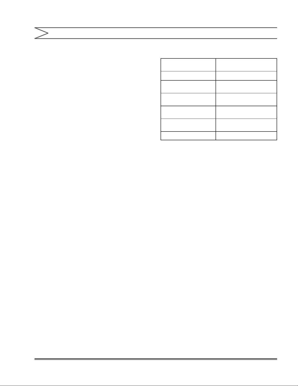
1.1 SPECIFICATIONS
Steady State
Accuracy / Turndown
Liquid Temperature:
Minimum Suction
Pressure:
Minimum Discharge
Back Pressure:
Hydraulic Fluid:
Ball Checks:
Gear Lubricant
Ratio: + 1% over 10:1
Turndown ratio.
+20°F to 250°F
3 PSIA minimum
(12 psi maximum vacuum).
35 psi above suction
pressure.
Mobile SHC-524 or
Equivalent.
Double ball checks in
suction and discharge.
SHC-634 or Equivalent.
5Instruction Manual
Page 6

SECTION 2 - INSTALLATION
2.1 UNPACKING
Pumps are shipped Free on Board (FOB) from the
factory and the title passes to the customer when
the carrier signs for receipt of it. The customer,
therefore, must le damage claims with the carrier.
The shipping crate should be carefully examined
upon receipt from the carrier to be sure there is no
obvious damage to the contents. Open the crate
carefully, as there are sometimes accessory items
fastened to the inside of the crate that may be lost
or damaged. Examine all material inside crate and
check against the packing list to be sure that all
items are accounted for and undamaged.
2.2 SAFETY PRECAUTIONS
When installing, operating, and maintaining an
HPD pump, keep safety considerations foremost.
Use proper tools, protective clothing, and eye
protection when working on the equipment and
install the equipment with a view toward ensuring
safe operation. Follow the instructions in this
manual and take additional safety measures
appropriate to the liquid being pumped.
Be extremely careful in the presence of hazardous
substances, (e.g. corrosives, toxics, solvents,
acids, caustics, ammables etc.).
2.3 MOUNTING
The HPD liquid end is shipped already mounted
to the appropriate pump. Mounting, therefore, is
simply a matter of securing the pump to a safe,
level surface. For further information on proper
pump mounting, see the appropriate pump
instruction manual.
2.4 PIPING CONNECTIONS
2.4.1 General
General piping instructions are given in the pump
drive instruction manual. No reciprocating plunger
pump can be expected to perform satisfactorily
unless those recommendations are followed.
Pay particular attention to plastic liquid ends,
as these units are relatively fragile and can be
damaged by the installation. For best results, avoid
straining the liquid end by installing a very short
section of exible tubing between rigid, xed piping
and suction and discharge cartridges on plastic
liquid ends.
NOTE:
Maximum safety and reliability may be ensured
by protecting liquid ends and piping with an
external relief valve installed in the system
discharge line.
6
Instruction Manual
Page 7

SECTION 2 - INSTALLATION
2.5 NPSH CONSIDERATIONS
The HPD liquid end is far superior to conventional
diaphragm liquid ends for suction lift and many
other NPSH critical applications. It’s patented
diaphragm and advanced design rell mechanism
give this liquid end truly high performance in these
applications.
For more NPSH information, refer to Milton Roy
web site (www.miltonroy.com) for aid in evaluating
applications for this liquid end.
2.6 TYPICAL PIPING
In order to adjust the HPD relief valve, it is
necessary to have a pressure gauge and a
shut OFF valve installed in the discharge line.
The pressure gauge must have a higher range than
the desired pump relief pressure, and should be
installed as close to the pump discharge connection
as possible. The shut OFF valve should be installed
downstream of the pressure gauge. These items
are not required for normal operation, but for
ease of pump maintenance and adjustment, it is
suggested that they be permanently piped into
the line.
Also see the instructions in the appropriate pump
instruction manual for additional typical piping
instructions.
7Instruction Manual
Page 8

SECTION 3 - OPERATION
3.1 PUMP START-UP PROCEDURE
(VARIABLE STROKE PUMPS)
DO NOT RUN THE MOTOR UNTIL
ALL START UP STEPS HAVE
BEEN COMPLETED. YOU COULD DAMAGE THE PUMP IF YOU
RUN THE MOTOR BEFORE ALL OF THE STEPS HAVE BEEN
COMPLETED. IT MAY BE NECESSARY TO TEST THE MOTOR
OFF THE PUMP TO INSURE PROPER DIRECTION AND
OPERATION. THE MOTOR DIRECTION IS CRITICAL. WIRE THE
MOTOR SO THAT IT ROTATES IN THE DIRECTION OF THE
ARROW CAST ON THE MOTOR MOUNT FLANGE. CONSULT
MANUFACTURER DOCUMENTATION FOR MOTOR START UP
RECOMMENDATIONS.
1. Follow the motor mounting procedure before
attempting to start your pumps. On some
pumps, the motor is mounted at the factory.
2. Make the proper electrical connections to the
motor per the manufacturer’s recommendations.
Make sure the motor is properly grounded.
3. Make sure that all of the mounting holes for the
pump base are used to securely tighten the base
to the mounting area.
8. Remove all of the tubing connecting the air bleed
valve (at the top of the displacement chamber
behind the discharge check valve). There is a
compression tting at the point where the tubing
enters the front catchall reservoir. Loosen the
nut and remove the tubing from this tting.
There is a tting connected to the air bleed
valve that needs to be removed. Remove all air
bleed valves from the top of the displacement
chamber.
9. The displacement chamber must be lled with,
ISO-32 (SHC-524) through the air bleed port.
If pump equipped with leak detection see
Section 5.
IF THE DISPLACEMENT
CHAMBER IS FILLED WITH THE
PLUNGER FULLY REARWARD, THE DIAPHRAGM COULD
RUPTURE AT START-UP. TO PROPERLY FILL THE
DISPLACEMENT CHAMBER, THE PLUNGER MUST BE
POSITIONED SO THAT IT IS TOP DEAD CENTER IN THE
DISPLACEMENT CHAMBER.
4. Do not run the motor until ALL start up steps
have been completed.
5. Remove the gear drive ll cap (the chamber
closest to the motor).
6. Fill the gear drive chamber with appropriate
gear lubricant (SHC-634). This oil was shipped
with the pump. Fill this chamber so that the oil
level is even with the midpoint of the sight glass.
Do not overll.
7. Remove the catchall chamber cover (closest to
the process liquid end of the pump) revealing
the plunger and bleed valve. Fill this chamber
with hydraulic oil, ISO -32 (SHC-524). This oil
was shipped with your pump, and is a lower
viscosity compared to the gear oil. The hydraulic
uid must ll the catchall chamber so that the
oil level is even with the midpoint of the sight
glass. Do not overll.
NOTE:
Two types of oils have been provided. They must
be added at the proper location.
10. With the plunger fully engaged in the
displacement chamber (pump at TDC, Top
Dead Center) adjust the stroke adjustment
mechanism until the indicating needle reads
100%. Either turn the hand wheel on a
micrometer, apply a 15-PSI supply signal
for a Pneumatic, or apply a 20-mA signal for
an Electronic actuator. In order to ll each
displacement chamber and fully purge the air
from the oil, rotate the motor either by hand
(by removing the fan cover and spinning the fan
by hand), or by rotating the motor electrically.
The motor may be jogged by turning the power
ON and OFF very quickly. (During this process
watch for air bubbles escaping the oil)
IT IS VERY IMPORTANT NOT TO
ROTATE THE MOTOR AT HIGH
SPEED, BECAUSE HYDRAULIC FLUID WILL BE FORCED FROM
THE AIR BLEED PORT AT A VERY HIGH VELOCITY.
8
Instruction Manual
Page 9

SECTION 3 - OPERATION
11. Rotate the motor shaft again so that the pump
is back at TDC (fully extended plunger into the
displacement chamber). Fill this chamber with
ISO-32 oil and check that no air bubbles are
present.
12. Replace the air bleed valve and tighten.
Use a pipe thread sealant to seal the threads.
Be very careful not to get any sealant into the
displacement chamber air bleed port. Place the
end of the tubing into the compression tting
and tighten the lock nut to secure the tubing.
13. On multiplex units, repeat these two steps for
each pump to insure proper hydraulic ll in
each displacement chamber.
14. Recheck the oil level in the catchall reservoir
and install the cover, screws and lock washers.
The gaskets have an adhesive backing that
should be removed and the gaskets should
be rmly attached to the covers using this
adhesive.
15. Make sure that all oil ll caps are securely
tightened to prevent oil leakage.
ALWAYS WEAR THE PROPER
PROTECTIVE GEAR WHEN
WORKING ON THE PUMP LIQUID END.
18. It is advisable to test the pump for proper
operation by testing it with water before you
use a process uid. Now ll the process liquid
ends with process uid.
TAKE ADDITIONAL SAFETY
MEASURES APPROPRIATE TO
THE LIQUID BEING PUMPED. BE EXTREMELY CAREFUL IN
THE PRESENCE OF HAZARDOUS SUB-STANCES
(CORROSIVES, TOXINS, SOLVENTS, ACIDS, CAUSTICS, AND
FLAMMABLES).
19. Loosen each process bleeder barb, if so
equipped, on each pump to bleed any air from
the liquid end. Connect a hose to this barb and
use caution if you are pumping a hazardous
chemical. After all process liquid ends have
been purged of air, you can tighten all bleeder
barbs to prevent leakage.
20. Now the motor can be started if and only if all
steps have been followed.
A. For constant speed motors, adjust the stroke
adjustment mechanism so that the indication
needle reads 25-30%. Gradually increase
the capacity adjustment mechanism and
increase back-pressure to insure that the
pump has time to purge all air from the
system.
16. Connect suction and discharge piping
manifolds. Use the proper gaskets and tighten
each ange per specication. Check that all
connections are tight including the check
valves, anges, air bleed valves and the motor
mount bolts.
17. Make sure the process bleeder barb, if so
equipped, is tight. It is located on the front
face of the pump directly under the discharge
check valve. This tting is used to purge any
air that is trapped in the process liquid end.
If this tting is loose when you ll the pump, a
stream of process uid will come out and create
a hazardous condition.
B. For a variable speed drive, the motor
should be run at a very slow speed between
75-100 revolutions per minute, and the pump
should have minimal process back pressure
for initial start-up. Gradually increase the
motor speed and increase back-pressure
to insure that the pump time to purge all air
from the system.
NOTE:
This concludes the start-up procedure. Please
follow these steps to insure start-up success
and reduce any risk of damage to the pump.
9Instruction Manual
Page 10

SECTION 3 - OPERATION
3.2 RELIEF VALVE ADJUSTMENT
THE PRESSURE RELIEF VALVE
IS FACTORY SET TO OPEN AT A
PRESSURE SLIGHTLY ABOVE THE PUMP MAXIMUM
OPERATING DISCHARGE PRESSURE; NEVER SET THE VALVE
AT ANY GREATER PRESSURE.
All HPD liquid ends have a built in relief valve that
allows hydraulic uid to return to the hydraulic uid
reservoir if excessive pressure builds up in the
discharge line. This effectively stops the pump from
pumping, since the forward stroke of the piston
will not displace the hydraulic uid and force the
diaphragm to ex.
The HPD liquid end relief valve may be adjusted
to operating conditions by the following procedure.
Adjust the relief valve after rst installing the pump
and after any maintenance procedures.
1. A pressure gauge and shut OFF valve must be
installed in the discharge line to complete this
procedure. If the necessary equipment is not
installed, refer to the “Typical Piping” instructions
in Section 2.
2. Make sure shut OFF valve is open. Start pump
and pump process liquid to drain or other safe
point to establish proper pumping action.
3. Set capacity control at 30%.
4. Close shut OFF valve slowly (“dead head” the
pump) and closely watch the pressure increase
on the pressure gauge. If pressure exceeds
desired value, quickly open shut OFF valve to
relieve pressure in line.
5. With shut OFF valve still closed, loosen relief
valve adjusting screw located on top of valve
until the maximum pressure gauge reading
reaches and maintains the relief valve pressure
setting desired.
6. After setting relief valve, make sure shut OFF
valve is fully open. Remove pressure gauge
from line or leave in place, as desired, and place
pump in routine service.
NEVER OPEN THE AIR PURGE
VALVE (IF EQUIPPED 0261)
DURING PRESSURIZED PUMP OPERATION.
7. The diaphragm head is equipped with an
air bleed purge valve built in just below the
discharge port. (Item 0350). The purpose of
this device is to vent entrapped air from the
diaphragm head during priming and start-up.
This end of this tting will accept exible tubing
in order to pipe OFF the solution to a non-
hazardous location. Immediately after priming,
the tting should be tightened.
KEEP HANDS AWAY FROM
RECIPROCATING PLUNGER
AND CROSSHEAD. DO NOT LEAVE PUMP OPERATING
UNATTENDED WITH SHUT OFF VALVE CLOSED. EXCESSIVE
PRESSURE CAN BUILD QUICKLY, POSSIBLY CAUSING
SEVERE DAMAGE TO PUMP AND / OR PIPING. SINCE THE
RELIEF VALVE IS NOT YET PROPERLY ADJUSTED, IT CAN NOT
BE RELIED ON TO LIMIT EXCESSIVE PRESSURE BUILD-UP. BE
SURE TO WATCH PRESSURE GAUGE VERY CAREFULLY AND
OPEN SHUT OFF VALVE IMMEDIATELY IF EXCESSIVE
PRESSURE DEVELOPS.
10
Instruction Manual
Page 11

SECTION 4 - MAINTENANCE
4.1 DIAPHRAGM REPLACEMENT
(FIGURE 2, SHEET 1 & 2)
The HPD diaphragm is extremely durable and often
lasts for many years of service. As a preventive
measure, however, Milton Roy recommends that
the diaphragms be replaced yearly to coincide
with annual check valve replacement. The liquid
end must be removed from the pump to replace
the diaphragm. The following is the diaphragm
replacement procedure:
1. Stop pump and relieve all pressure from system.
Isolate the liquid end from all sources of process
liquid with appropriate valving and purge liquid
end of all process uid.
2. Disconnect both the suction inlet and discharge
outlet from the piping system.
NOTE:
Approximately one pint of oil will still be present
in the contour plate area which will be released
when the diaphragm is removed. Prepare your
work area accordingly.
3. Remove the catchall cover and drain catchall of
hydraulic oil by removing pipe plug at bottom of
casing.
4. Completely loosen the piston rod retention nut
(1750) located inside the catchall.
5. Disconnect all tubing that connects the liquid
end to the pump body.
NOTE:
The liquid end is very heavy (150 lbs. or more).
A hoist is required to move it.
7. Remove relieve valve (1040) and rell valve
(400) from displacement chamber.
8. Place liquid end, diaphragm head up
(bolts (710) on top), on a bench or other clean,
at, and convenient working area.
9. Once the diaphragm head is adequately
supported, the diaphragm head bolts (710)
can be removed. Carefully pull the diaphragm
head (700) away from the displacement
chamber. The diaphragm (670) may pull OFF
with the diaphragm head or remain with the
displacement chamber. Remove diaphragm
(670). (When equipped with leak detection
(See Section 5) remove two diaphragms,
leak detection ring A (8080), leak detection
ring B (8081), and leak detection ring spacer
(8082). Leak detection rings A, leak detection
rings B, and leak detection ring spacer can be
reused).
10. Clean all sealing surfaces and install new
diaphragm (670). (When equipped with
leak detection (See Section 5) install two
diaphragms, leak detection ring A (8080), leak
detection ring B (8081), and leak detection
ring spacer (8082) removed previously.
Apply a small amount of mineral oil between
the diaphragms. Stacked diaphragms and
rings may be aligned using the three small
holes as a guide).
NOTE:
Apply anti-seize thread lubricant to the bolts.
6. Support liquid end with a hoist and unscrew
nuts (980) that hold the displacement chamber
(630) to the pump body. Pull liquid end and
plunger assembly (2000) OFF, being careful
to protect the plunger from damage. Carefully
raise liquid end and plunger over catchall and
pull plunger from liquid end, allowing hydraulic
uid to drain back into catchall. Pull plunger
rmly but carefully, being careful not to bend or
otherwise damage the plunger.
11. Reinstall liquid end on catchall, using the bolts
as a guide.
NOTE:
The bolt torque value stamped on the head only
applies to the material grade supplied with the
pump.
11Instruction Manual
Page 12

SECTION 4 - MAINTENANCE
12. Torque bolts in sequence to one half of the nal
torque value stamped on the head. Follow the
bolt torque pattern as stamped on the head.
Repeat the torque sequence until bolts are
tightened to nal torque value.
13. Reconnect suction inlet and discharge outlet to
piping system. Follow Section 5 if your pump
is equipped with leak detection.
14. Fill the liquid end with hydraulic oil (refer to
above “INITIAL START-UP” procedure).
4.2 HYDRAULIC OIL REPLACEMENT
Inspect and replace hydraulic oil on same schedule
as the pumps gear drive lubricant (or whenever
diaphragm is replaced). Annual replacement is
recommended.
4.3 MARS REFILL VALVE (400)
The MARS rell valve (400) requires no periodic
maintenance. Clean hydraulic oil is critical for
proper operation.
Strainer service: while replacing the hydraulic
oil, it is also recommended that the hydraulic oil
strainer be replaced. The strainer, (390) which
screws into the displacement chamber can become
fouled or clogged over time.
NOTE:
Federal law prohibits handling of equipment that
is not accompanied by an OSHA Safety Data
Sheet (SDS). A completed SDS must be packed
in the ship-ping crate with any pump returned
to the factory. These safety precautions will aid
the troubleshooting and repair procedure and
preclude serious injury to repair personnel from
hazardous residue in pump liquid end. A Safety
Data Sheet must accompany all returns.
4.5 RECOMMENDED SPARE PARTS
Be Prepared. To avoid delays in repairs, the
following spare parts should be ordered for each
pump:
One Routine Preventive Maintenance Kit, which
contains replacements for those parts which
are subject to wear; specically the ball checks,
check valve seats, gaskets, and the hydraulic uid
strainer. Replacing these parts annually with an
RPM kit can reduce the possibility of unexpected
downtime and will help to extend pump life.
Parts orders must include the following information:
1. Serial number (found on nameplate)
2. Model number (found on nameplate)
3. Quantity required
4. Part number
Screw the valve back into the chamber. If the valve
is damaged or broken, replace the entire assembly.
4.4 RETURNING UNITS TO THE FACTORY
Pumps will not be accepted for repair without a
Return Material Authorization, available from the
factory or other authorized Customer Service
Department. Pumps returned to the factory for
repairs should be clearly labeled to indicate the
liquid being pumped. Process liquid should be
ushed from the pump liquid end before the pump
is shipped.
12
Instruction Manual
5. Part description
Always include the serial and model numbers in all
correspondence regarding the unit.
Page 13

SECTION 4 - MAINTENANCE
4.6 ROUTINE PREVENTIVE MAINTENANCE
BEFORE ANY MAINTENANCE,
RELIEVE ALL PRESSURE FROM
SYSTEM, ISOLATE LIQUID END FROM ALL SOURCES OF
PROCESS LIQUID WITH APPROPRIATE VALVING, AND PURGE
LIQUID END OF ALL PROCESS LIQUID.
All inquiries on part order should be addressed to
your local Milton Roy sales representative or sent
to: www.miltonroy.com.
4.7 HYDRAULIC OIL REPLACEMENT
Inspect and replace hydraulic oil on the same
schedule as the pump’s gear drive lubricant
(see the appropriate pump drive instruction manual
for this information). Semiannual replacement is
recommended, and can be scheduled to coincide
with season oil changes.
To replace the hydraulic oil:
1. Remove the catchall cover by unscrewing the
four screws, which hold it on.
2. Place a container under the pump catchall to
catch the oil and unscrew the catchall drain
plug.
3. When oil has finished draining, make sure
that the area around the drain hole is clean.
Screw drain plug back in securely.
4. Fill the catchall to the top of the oil seal that
surrounds the crosshead with new, clean oil.
Use hydraulic oil or any good quality type A
automobile transmission uid.
5. Replace the catchall cover the screw rmly in
place.
NOTE:
It is not necessary to purge the liquid end
displacement chamber of oil during annual oil
replacement.
6. Dispose of oil according to federal, state, or local
codes that may apply.
4.8 CHECK VALVE MAINTENANCE
4.8.1 Disassembly
BEFORE PERFORMING ANY
MAINTENANCE ON THE CHECK
VALVES, RELIVE ALL PRESSURE FROM SYSTEM, ISOLATE
LIQUID END FROM ALL SOURCES OF PROCESS LIQUID WITH
APPROPRIATE VALVING, AND PURGE LIQUID END OF ALL
PROCESS FLUID.
After insuring that all system pressure has been
relieved and that all hazardous process liquids
have been ushed from the liquid end, disconnect
both the suction inlet and discharge outlet from the
system piping.
1. Loosen the retaining nut, then remove.
Once disassembled, the O-rings should be
discarded.
2. Check valves may be removed. A compressed
O-ring provides the seal to the head.
Inspect the balls carefully. If they are smooth,
round and free of deposits or pits, then they
are suitable for continued use. Examine the
check valve seats. The area of the seat where
it meets the ball (the un-chamfered side) must
be in near perfect condition for continued use.
Any imperfection visible on the seating surface
(pits, erosion, cracks, or a ball shaped contour
greater than 0.030 deep) makes the seat
unusable. If both the balls and seats are in good
condition, then the length of time between parts
replacement may be lengthened. If the balls and
seats are severely damaged, then the length
of time between parts replacement should be
shortened.
4.8.2 Re-assembly
1. Replace O-ring on the check valves.
Lubricate the O-rings and check valve threads
before assembly.
2. Attach port adapter and tighten retaining nut.
13Instruction Manual
Page 14

SECTION 4 - MAINTENANCE
4.9 CORRECTIVE MAINTENANCE
4.9.1 Relief Valve Assembly
The relief valve assembly operates in filtered
hydraulic oil and should require maintenance
only if unusual circumstances occur, such
as if corrosive media contaminates the fluid.
Assembly and disassembly is straightforward.
Field servicing should be limited to inspection and
cleaning only. Repairs of this critical component
should only be carried out by an authorized
Milton Roy repair facility.
14
Instruction Manual
Page 15

SECTION 5 - LEAK DETECTION (PRESSURE SENSING SYSTEM)
5.1 DESCRIPTION
(FIGURE 2, SHEET 1 & 2)
Milton Roy’s pumps are, by design, leakproof
and durable. In some applications, however,
added assurance is desired to protect the pump
from hostile chemicals, or protect the process
from contamination by hydraulic uids. For these
situations, Milton Roy has developed a highly
reliable diaphragm rupture detection system.
The diaphragm rupture detection system is an
optional feature, available on the Critical Service
line of metering pumps, which is used to detect
and signal if a hole or tear occurs in one or both
diaphragms. The system consists of two PTFE
diaphragms separated by four leak detection
rings (two A rings (8080) & two B rings (8081)).
Pressure in the four leak detection rings between
the diaphragms is monitored via a pressure
gauge. A machined port in the displacement
chamber at (5021) connects the diaphragms and
rings with tubing, gauge, and or pressure switch.
A low cracking pressure check valve (5000) and
a bleed valve (5100) are located between the
displacement chamber and the pressure gauge.
5.2 PRINCIPLE OF OPERATION
The system consists of two separate diaphragms,
four leak detection rings, leak detection ring
spacer (8082), and a pressure gauge (5030) or
switch (1250). During normal operation, the two
diaphragms are pushed tightly together and are
separated only around their outside edge by the
rings. Because there is no uid and very little air
between the two diaphragms, the system does not
experience pressure from the process when both
diaphragms are intact. The pressure is therefore
at atmospheric pressure, and the pressure gauge
displays 0 psi. The rupture detection system
senses process pressure only when one of the
diaphragms rupture. In the event of a rupture in
either diaphragm, uid rushes into the rings, and
the pressure at the ring rises rapidly to the pump’s
operating pressure. This pressure will be displayed
directly on the pressure gauge for visual indication.
An optional pressure switch is also available to
shut down the pump or provide an alarm signal.
The pressurized uid trapped between the pressure
gauge and the check valve can be relieved via the
bleed valve after the pump is shut down and system
pressure relieved.
5.3 SPECIFICATIONS
Maximum
Pressure Ratings:
Materials:
Flow Rate:
Accessories:
Same as pump rating.
Diaphragms: PTFE
Leak Detection Ring /
Tubing: Steel 304SS or
316SS
Derate ow by 5% on all
pumps
Pressure Gauge: 316SS
liquid lled (Standard)
Pressure Switch
W/Gauge : NEMA 4 or
Explosion Proof (optional)
15Instruction Manual
Page 16

SECTION 6 - INSTALLATION & OPERATION (PRESSURE SENSING SYSTEM)
The Diaphragm Rupture Detection System is
usually shipped already mounted to the pump.
Installation, therefore, is usually only a matter of
piping in the pump, and wiring the pressure switch
if one is provided.
6.1 UNPACKING
Units are shipped Free on Board (FOB) factory
and the title passes to the customer when the
carrier signs for receipt of the unit. In the event
that damages occur during shipment, it is the
responsibility of the customer to notify the
carrier immediately and to le a damage claim.
Carefully examine the shipping crate upon receipt
from the carrier to be sure there is no obvious
damage to the contents. Open the crate carefully so
accessory items fastened to the inside of the crate
will not be damaged or lost. Examine all material
inside crate and check against packing list to be
sure that all items are accounted for and intact.
6.2 SAFETY PRECAUTIONS
6.3 DISASSEMBLY / ASSEMBLY
(REFER TO DRAWING 1029026000,
FIGURE 2, SHEET 1 & 2)
LOOSENING ANY HYDRAULIC
CONNECTIONS OR OPENING
ANY VALVES COULD CAUSE PROCESS LIQUID TO BE
RELEASED UNDER PRESSURE. CAREFULLY DISCONNECT
PUMP FROM ALL ELECTRICAL AND HYDRAULIC SERVICE
BEFORE PERFORMING ANY MAINTENANCE.
1. After shutting down the pump and relieving
system pressure, disconnect all hydraulic
connections.
2. Drain the oil from the catchall.
3. Disassemble the diaphragm head from the
pump body following the instructions in
Section 4.
4. Remove diaphragms (670) and discard along
with four leak detection rings (8080 and
(8081), and leak detection ring spacer (8082).
Items (8080, 8081, and 8082) can be reused
if not damaged by process fluid. Refer to
Figure 2, Sheet 2, Detail C as needed.
When installing, operating, and maintaining a
Critical Service pump with Diaphragm Rupture
Detection, keep safety considerations foremost.
Use proper tools, protective clothing, and eye
protection when working on the equipment
and install the equipment with a view toward
ensuring safe operation. Follow the instructions
in this manual and take additional safety
measures appropriate to the liquid being pumped.
Be extremely careful in the presence of hazardous
substances (e.g., corrosives, toxics, solvents,
acids, caustics, ammables etc.).
IF THE PROCESS FLUID IS
HYDROGEN PEROXIDE OR
ANOTHER STRONG OXIDIZING AGENT, MINERAL OIL SHOULD
NOT BE USED BETWEEN THE DIAPHRAGMS. SUBSTITUTE
WITH A CHLOROTRIFLUOROETHYLENE POLY-MER FLUID
SUCH AS FLOUROLUBE.
5. Clean all sealing surfaces and install new
diaphragms (670), leak detection ring A (8080),
leak detection ring B (8081), and leak detection
ring spacer (8082), leak detection ring A (8080),
leak detection ring B (8081) removed previously
(Figure 2, Sheet 1, Detail C). Apply a small
amount of mineral oil between the diaphragms.
Stacked diaphragms and rings may be aligned
using the three small holes as a guide.
Make sure diaphragms (670) t into pocket on
diaphragm head (700).
16
Instruction Manual
Page 17

SECTION 6 - INSTALLATION & OPERATION (PRESSURE SENSING SYSTEM)
6. Reassemble diaphragm head following
Section 4.
7. Once the suction inlet and discharge outlets are
connected to piping system mount the switch
bracket (5090, Figure 2 Sheet 2) then the
remaining components should be tted nger
tight and oriented as shown.
NOTE:
Check the ow direction arrow on the check
valve. The check valve must be assembled with
the arrow pointed toward the pressure gauge
or pressure switch as shown in the gures.
Improper operation will result if the check valve
is not installed correctly.
8. Check all threaded and tube connections to
make sure they are tight.
IMPORTANT
9. Remove the pipe plug(s) and open the bleed-
valve(s). Follow the oil ll and start up procedure
in manual.
10. Leaving the bleed valve(s) open, run the
pump at 100% capacity and normal operating
pressure for 10 minutes. This procedure
purges any excess air and oil from in between
the diaphragms. If too much mineral oil was
placed between the diaphragms in step 5,
some will leak out from the bleed valve(s) at
this point. Lubricant leakage is acceptable.
6.4 ELECTRICAL CONNECTIONS
THIS SECTION ONLY APPLIES TO MODELS
EQUIPPED WITH THE PRESSURE SWITCH
ALARM OPTION.
The diaphragm leak detection system can be
equipped with a pressure switch which can be
wired to activate an alarm or shut down the pump
in the event of a diaphragm failure. This switch is
either NEMA 4 (indoor / outdoor, weather and dust
proof) or Explosion Proof (for hazardous locations).
In both cases the switch relay is single-pole double-
throw (SPDT), normally open or normally closed
and rated for 15 amps, 125/240/480 VAC resistive.
6.5 NEMA 4 PRESSURE SWITCH WIRING
The switch terminals are accessed by removing the
two screws retaining the cover and cover gasket.
A 1/2” NPT conduit connection is provided in the
switch enclosure.
6.5.1 Wiring
Unscrew the switch cover to access the wiring
connections. A 3/4” NPT conduit connection
is provided in the switch enclosure. Replacing
the cover hand tight (5 full threads engaged) is
sufcient to maintain proper protection. Additional
tightening may be required to fully engage the
O-ring and seal enclosure for rain tight protection.
11. Close the bleed valve(s) and replace the pipe
plug(s). The leak detector assembly is now
complete.
12. Additional oil may need to be purged again.
Return to step 10.
17Instruction Manual
Page 18

SECTION 6 - INSTALLATION & OPERATION (PRESSURE SENSING SYSTEM)
6.6 EXPLOSION PROOF PRESSURE
SWITCH
ALWAYS WIRE IN ACCORDANCE
WITH LOCAL OR NATIONAL
CODES. BE SURE ALL LIVE SUPPLY CIRCUITS ARE
DISCONNECTED BEFORE WIRING TO THE SWITCH. MAXIMUM
RECOMMENDED WIRE SIZE IS #14 AWG.
The three switch terminals are clearly labeled
“Com” (common), “NO” (normally open), and
“NC” (normally closed). A grounding screw is
also provided. Keep wires as short as possible
to prevent interference with the plunger and
differential switch wheel inside the switch.
Customer Connections
COM
NO
NC
6.7 START-UP
1. Refer to the manual for pump installation and
start-up instructions.
2. During the initial installation, following any
disassembly of the leak detection system, or if
the pump has not been operated for a prolonged
period, a short break-in procedure for the leak
detector system is required. On duplex pumps,
be sure to follow directions on both sides of the
pump.
a. Open the bleed valve(s) on the leak detection
system.
b. Operate the pump at 100% capacity and
normal system operating pressure. Air and a
small amount of oil may leak from the bleed
valve(s).
c. After a minimum of ten minutes of operation,
close the bleed valve(s).
(Violet)
(Blue)
NC
NO
Internal SPDT Switch Rated
15A, 120/240/480 VAC
(Black)
COM
Figure 1. Pressure Switch Wiring Diagram
IMPORTANT
Connections must always be made through cable
connectors which maintain the integrity of the
NEMA 4 switch or Explosion Proof enclosure.
The break-in operation purges any air and excess
oil which may be trapped in the intermediate ring(s).
The leak detection system is now operational.
18
Instruction Manual
Page 19

1. Please refer to the Bill of Material and assembly
for spare parts.
2. Use the drawing to identify the sequence for the
part.
3. The sequence number is used on the drawing
and Bill of Material.
4. Parts should be ordered by the “Part Number”
listed in the Bill of Material.
5. Also reference the sequence number of the part,
since component upgrades occur.
SECTION 7 - PARTS
19Instruction Manual
Page 20

20 Instruction Manual
Page 21

21Instruction Manual
Page 22

BILL OF MATERIAL
FOR
MCB2418GPCCDEAV6H311C522
MR SO #2441959 / PO6019493
MILROYAL® C
MODEL # MCB241
TAG # 41-67-2011, 41-67-2012
ITEM
NUMBER
261 20352 BARB,AIR BLEED 316/316LSS 1 EA
262 A5-1007 OR -007 VITON 1 EA
300 40538 ‘O’ RING 2-176 VITON 1 EA
350 30342 AIR BLEED VALVE HI TEMP 1 EA
351 21801 PLUG, AIR BLEED VALVE 1 EA
352 V-112 POPPET O-RING / VITON STD. 1 EA
390 2450021000 STRAINER FITTING HPD 1 EA
400 20749 REFILL VALVE BODY 1 EA
420 L10626 BALL, 1/4” 440C SS 1 EA
430 20024 SPRING MARS CS 1 EA
440 60668 FLATWASHER M4 ZINC PLT 1 EA
441 40605 RETAINING RING #RCLBHO0037STPA 1 EA
630 21269 DISP. CHMBR ‘116’ SLEEVED 1 EA
643 20663 MARS BUTTON 1 EA
644 60677 SPRING, MARS BUTTON 1 EA
645 60673 POPPET MARS VALVE 1 EA
646 40570 WALDES RETAINING RING X5133-31 1 EA
647 4020095011 PLUG 1/8 NPT SOCKET HEX HEAD 1 EA
648 4050025144 SOC HD SCR #10-24X1-1/2 STL 2 EA
649 4080068015 O-RING 2-111 VITON / USE V-111 1 EA
650 20658 CONTOUR PLATE 7.50 MILC BAR 1 EA
670 40515 DIAPHRAGM - GYLON 8.730 X .060 2 EA
700 20747 DIAPHRAGM HEAD ‘116’BAR ASTM A479 1 EA
710 40525-G7 SOC HD CAP SCR 1 1/4-7 X 5 1/2 12 EA
711 40893 WASHER, FLAT 1 1/4 NARROW 12 EA
790 20684 CAGE - 1-1/2” BALL CHECKS 316SS 4 EA
800 40564 O-RING , TFE ENC VITON,V-133 4 EA
805 20683 SEAT - 1-1/2” BALL CHECKS 316SS 4 EA
810 4070014272-G7 BALL 1-1/2 316SS 4 EA
815 20680 CHECK VALVE BODY - 1-1/2” 2 EA
816 40565 O-RING, TFE ENC VITON, V-142 4 EA
820 53720 FLANGE WELD ASSY 1” 600# VERT 2 EA
PART NUMBER NOMENCLATURE QUANTITY U/I
22 Instruction Manual
Page 23

ITEM
NUMBER
870 40791 ‘O’RING 2-230 NITRILE 70 DURO 1 EA
880 21268 SLEEVE, PLUNGER BORE 1.50 DIA 1 EA
881 4050020136 HEX HD SCR 1/2-13X1-1/4 ULTRA 5 EA
950 2190063006 HALF MOON STEEL MILROY HPD ALL 2 EA
960 2720026406 PLUNGER ADAPTER 7/8 HOLE CRS 1 EA
968 2250028099 GASKET 5-1/2ID LE TO DRIVE HSG 1 EA
970 4040044022 SPRING LOCK WASHER 5/8 18.8SS 4 EA
980 4050021151 HEX HD SCR 5/8-11X1-3/4STL GR2 4 EA
990 4020001124 HXPIPEBSHG 1X1/2 304SS 1 EA
1000 4020052012 NIPTHRDSCH40 1/2X1-1/8 304SS 1 EA
1005 42170 TEE3000#THRD 1/2 304SS 1 EA
1010 4020001054 HXPIPEBSHG 1/2X1/4 304SS 1 EA
1020 4020553152 MALE ELBOW 1/2 NPT X 3/8 TUBE 1 EA
1021 A1-0013 MELBOW 1/4T 1/4P SS 1 EA
1030 C7-0028 3/8” 316 SEAMLESS .035W 12 IN
1031 C7-0027 1/4” 316 SEAMLESS .035W 24 IN
1040 4070177051 RELIEF VALVE 50/2500 PSI 1 EA
1051 A1-0007 MCONN 3/8T 1/4NPT SS 1 EA
1052 A1-0003 MCONN 1/4T 1/8P SS 1 EA
2000 53744 PLUNGER ASSEMBLY 1 1/2” 1 EA
4040 4070317020 MINERAL OIL-NOT FOR RESALE 1 OZ
4990 C7-0044 1/8” 316 SEAMLESS .035W 24 IN
5000 40065 CHECK VALVE 1/8TUBE 1/3PSI 316SS 1 EA
5020 40061 TUBE CONN 1/8 TUBEX 1/8NPT 316SS 2 EA
5030 53716 GAUGE, PRES, 2.5”, ASHCRO, 2000PSI 1 EA
5031 4050263050 PAN HD SCR #4-40X1/2 ZNCR 3 EA
5032 4040095023 SPRING LOCK WASHER #4 18.8SS 3 EA
5033 C0-0051 4-40 NUT SS 3 EA
5050 40062 TEE 1/8NPT FEMALE 316SS 1 EA
5070 40067 RED ADAPTER 1/4F X1/8M NPT 316SS 1 EA
5090 21094 SUPPORT BRACKET,SWITCH / GAGE 1 EA
5092 4050016095 HEX HD SCR 1/4-20X3/4 18.8SS 2 EA
5100 40063 BLEED VALVE 1/8 NPT 316SS 1 EA
8080 40610 LEAK DETECTION RING ‘A’ 2 EA
8081 40611 LEAK DETECTION RING ‘B’ 2 EA
8082 40609 SPACER RING ‘116’ RUP. DET. 1 EA
8083 40790 O-RING, TFE ENC VITON, 2-178 1 EA
PART NUMBER NOMENCLATURE QUANTITY U/I
23Instruction Manual
Page 24

BILL OF MATERIAL
FOR
MCB2018JPCCCEAV6H311C522
MR SO #2441959 / PO6019493
MILROYAL® C
MODEL # MCB201
TAG # 40-67-3316 A/B, 40-67-3326 A/B, 40-67-3336 A/B, 40-67-3346 A/B
ITEM
NUMBER
261 20352 BARB,AIR BLEED 316/316LSS 1 EA
262 A5-1007 OR -007 VITON 1 EA
300 40538 ‘O’ RING 2-176 VITON 1 EA
350 30342 AIR BLEED VALVE HI TEMP 1 EA
351 21801 PLUG, AIR BLEED VALVE 1 EA
352 V-112 POPPET O-RING / VITON STD. 1 EA
390 2450021000 STRAINER FITTING HPD 1 EA
400 20749 REFILL VALVE BODY 1 EA
420 L10626 BALL, 1/4” 440C SS 1 EA
430 20024 SPRING MARS CS 1 EA
440 60668 FLATWASHER M4 ZINC PLT 1 EA
441 40605 RETAINING RING #RCLBHO0037STPA 1 EA
630 21269 DISP. CHMBR ‘116’ SLEEVED 1 EA
643 20663 MARS BUTTON 1 EA
644 60677 SPRING, MARS BUTTON 1 EA
645 60673 POPPET MARS VALVE 1 EA
646 40570 WALDES RETAINING RING X5133-31 1 EA
647 4020095011 PLUG 1/8 NPT SOCKET HEX HEAD 1 EA
648 4050025134 SOC HD SCR #10-24X1-1/4 STL 2 EA
649 4080068015 O-RING 2-111 VITON / USE V-111 1 EA
650 20658 CONTOUR PLATE 7.50 MILC BAR 1 EA
670 40515 DIAPHRAGM - GYLON 8.730 X .060 2 EA
700 20747 DIAPHRAGM HEAD ‘116’BAR ASTM A479 1 EA
710 40524 WASHER SAE HI STRENGTH 1 1/4 12 EA
711 40525-G7 SOC HD CAP SCR 1 1/4-7 X 5 1/2 12 EA
790 20684 CAGE - 1-1/2” BALL CHECKS 316SS 4 EA
800 40564 O-RING , TFE ENC VITON,V-133 4 EA
805 20683 SEAT - 1-1/2” BALL CHECKS 316SS 4 EA
810 4070014272-G7 BALL 1-1/2 316SS 4 EA
815 20680 CHECK VALVE BODY - 1-1/2” 2 EA
816 40565 O-RING, TFE ENC VITON, V-142 4 EA
PART NUMBER NOMENCLATURE QUANTITY U/I
24 Instruction Manual
Page 25

ITEM
NUMBER
820 53720 FLANGE WELD ASSY 1” 600# VERT 2 EA
870 4080095215 O-RING 2-230 VITON 1 EA
880 22731 SLEEVE, PLUNGER BORE 1.25 DIA 1 EA
881 4050020136 HEX HD SCR 1/2-13X1-1/4 ULTRA 5 EA
950 2190063006 HALF MOON STEEL MILROY HPD ALL 2 EA
960 2720026406 PLUNGER ADAPTER 7/8 HOLE CRS 1 EA
968 2250028099 GASKET 5-1/2ID LE TO DRIVE HSG 1 EA
970 4040044022 SPRING LOCK WASHER 5/8 18.8SS 4 EA
980 4050021151 HEX HD SCR 5/8-11X1-3/4STL GR2 4 EA
990 4020001124 HXPIPEBSHG 1X1/2 304SS 1 EA
1000 4020052012 NIPTHRDSCH40 1/2X1-1/8 304SS 1 EA
1005 42170 TEE3000#THRD 1/2 304SS 1 EA
1010 4020001054 HXPIPEBSHG 1/2X1/4 304SS 1 EA
1020 4020553152 MALE ELBOW 1/2 NPT X 3/8 TUBE 1 EA
1021 A1-0013 MELBOW 1/4T 1/4P SS 1 EA
1030 C7-0028 3/8” 316 SEAMLESS .035W 12 IN
1031 C7-0027 1/4” 316 SEAMLESS .035W 12 IN
1040 4070177051 RELIEF VALVE 50/2500 PSI 1 EA
1051 A1-0007 MCONN 3/8T 1/4NPT SS 1 EA
1052 A1-0003 MCONN 1/4T 1/8P SS 1 EA
2000 53719 PLUNGER ASSEMBLY 1 1/4” 1 EA
4040 4070317020 MINERAL OIL-NOT FOR RESALE 1 OZ
4990 C7-0044 1/8” 316 SEAMLESS .035W 12 IN
5000 40065 CHECK VALVE 1/8TUBE 1/3PSI 316SS 1 EA
5020 40061 TUBE CONN 1/8 TUBEX 1/8NPT 316SS 1 EA
5030 53716 GAUGE,PRES,2.5”,ASHCRO,2000PSI 1 EA
5031 4050263050 PAN HD SCR #4-40X1/2 ZNCR 3 EA
5032 4040095023 SPRING LOCK WASHER #4 18.8SS 3 EA
5033 C0-0051 4-40 NUT SS 3 EA
5050 40062 TEE 1/8NPT FEMALE 316SS 1 EA
5070 40067 RED ADAPTER 1/4F X1/8M NPT 316SS 1 EA
5090 21386 BRACKET, LEK DET, GAGE MCB 1 EA
5092 40710 SCREW 3/8-16X3/4 SHCS, 18.8SS 2 EA
5100 40063 BLEED VALVE 1/8 NPT 316SS 1 EA
8080 40611 LEAK DETECTION RING ‘B’ 2 EA
8081 40610 LEAK DETECTION RING ‘A’ 2 EA
8082 40609 SPACER RING ‘116’ RUP. DET. 1 EA
8083 40790 O-RING, TFE ENC VITON, 2-178 1 EA
PART NUMBER NOMENCLATURE QUANTITY U/I
25Instruction Manual
Page 26

BILL OF MATERIAL
FOR
MCB1418BPBCDEAV6ST33C5C2
MR SO #2441959 / PO6019493
MILROYAL® C
MODEL # MCB141
TAG # 40-67-3111 A/B/C/D
ITEM
NUMBER
261 20352-G7 BARB,AIR BLEED 316SS 1 EA
262 A5-1007 OR -007 VITON 1 EA
300 40780 O-RING, TFE ENC VITON, V-167 1 EA
350 30342 AIR BLEED VALVE HI TEMP 1 EA
351 21801 PLUG, AIR BLEED VALVE 1 EA
352 V-112 POPPET O-RING/VITON STD. 1 EA
390 2450021000 STRAINER FITTING HPD 1 EA
400 20749 REFILL VALVE BODY 1 EA
420 L10626 BALL, 1/4” 440C SS 1 EA
430 20024 SPRING MARS CS 1 EA
440 60668 FLATWASHER M4 ZINC PLT 1 EA
441 40605 RETAINING RING #RCLBHO0037STPA 1 EA
630 53777 DISP. CHMBR .875 ‘72’ MIL C 1 EA
643 20663 MARS BUTTON 1 EA
644 60677 SPRING, MARS BUTTON 1 EA
645 60673 POPPET MARS VALVE 1 EA
646 40570 WALDES RETAINING RING X5133-31 1 EA
647 OS601 PLUG - 1/8” NPT, SOC HEX HD 1 EA
648 4050025134 SOC HD SCR #10-24X1-1/4 STL 2 EA
649 40534 ‘O’ RING 2-109 NITRILE 1 EA
650 20659 CONTOUR PLATE 4.50 MILC BAR 1 EA
670 40516 DIAPHRAGM -6” OD X .030 THK 2 EA
700 21092 DIAPHRAGM HEAD ‘72’ L/D 1 EA
710 43195-G7 SOC HD SCR 7/8-9X4-1/2 ST XYLN 10 EA
711 40749 WASHER 7/8 AN 960 C ULTRA COAT 10 EA
790 22710-G7 CAGE 3/4 BALL, SLURRY SERVICE 4 EA
800 2250043075 SEAL .915ID 1.197OD .141THK 4 EA
805 41054-G7 SEAT,HARDENED INSERT ASSEMBLY 4 EA
810 4070015191 BALL 3/4 CERAMIC AD995 4 EA
815 20678-G7 CHECK VALVE BODY - 1” 2 EA
816 40566 O-RING, TFE ENC VITON,M V-128 4 EA
820 52861 FLANGE WELD ASSY 1/2” 600#VERT 2 EA
PART NUMBER NOMENCLATURE QUANTITY U/I
26 Instruction Manual
Page 27

ITEM
NUMBER
950 2190063006 HALF MOON STEEL MILROY HPD ALL 2 EA
960 2720026406 PLUNGER ADAPTER 7/8 HOLE CRS 1 EA
968 2250028099 GASKET 5-1/2ID LE TO DRIVE HSG 1 EA
970 4040044022 SPRING LOCK WASHER 5/8 18.8SS 4 EA
980 4050032164 SOC HD SCR 5/8-11X2 ULTRA COAT 4 EA
990 A2-0066 BUSHING RED 1 X 1/4 SS 1 EA
1000 HN1414304 SS-4-HN 1 EA
1005 A2-0115 TEE 1/4 SS 1 EA
1020 L11439 ELBOW 3/8ODTX1/4MPT 316SS 1 EA
1021 A1-0013 MELBOW 1/4T 1/4P SS 1 EA
1030 41028 TUBE MECH 3/8 ODX.035WALL 317L 18 IN
1031 41027 TUBE MECH 1/4 ODX.035WALL 317L 24 IN
1040 53779 RELIEF VLV ASSY 1500-2250 PSIG 1 EA
1051 A1-0007 MCONN 3/8T 1/4NPT SS 2 EA
1052 A1-0003 MCONN 1/4T 1/8P SS 1 EA
2000 2120062110 PLUNGER ASSEMBLY 7/8” 1 EA
4040 4070317020 MINERAL OIL-NOT FOR RESALE 1 OZ
4990 C7-0044 1/8” 316 SEAMLESS .035W 12 IN
5000 40065 CHECK VALVE 1/8TUBE 1/3PSI 316SS 1 EA
5020 40061 TUBE CONN 1/8 TUBEX 1/8NPT 316SS 1 EA
5030 53716 GAUGE,PRES,2.5”,ASHCRO,2000PSI 1 EA
5031 4050263050 PAN HD SCR #4-40X1/2 ZNCR 3 EA
5032 4040095023 SPRING LOCK WASHER #4 18.8SS 3 EA
5033 C0-0051 4-40 NUT SS 3 EA
5050 40062 TEE 1/8NPT FEMALE 316SS 2 EA
5070 40067 RED ADAPTER 1/4F X1/8M NPT 316SS 1 EA
5090 21094 SUPPORT BRACKET,SWITCH / GAGE 1 EA
5092 40710 SCREW 3/8-16X3/4 SHCS, 18.8SS 2 EA
5100 40063 BLEED VALVE 1/8 NPT 316SS 1 EA
8080 20847 LEAK DETECTION RING ‘A’ 2 EA
8081 20848 LEAK DETECTION RING ‘B’ 2 EA
8082 53965 MOD. SPACER RING’72’ 316SS 1 EA
8083 40781 O-RING, TFE ENC VITON, V-165 1 EA
PART NUMBER NOMENCLATURE QUANTITY U/I
27Instruction Manual
Page 28

DRILL 1/4” O THRU AS
BREATHER HOLE FOR PISTON
2020
2030
2050
1040
2.25
OIL LEVEL
330
340
990
2010
SEALS INSTALLED
BACK TO BACK
10
REF
DETAIL
925
FOR HPD
HOUSING
810
820
830
840
780
760
790
800
1075
1076
1070
720
1060
635
1080
710
670
700
650
640
630
3010
3000
28 Instruction Manual
Page 29

5033
5032
5031
5090
5030
5040
5050
5094
5100
5096
5097
5000
4990
4980
5092
5091
5020
5010
5093
0670
8081
8080
8082
8083
ENLARGED SECTION
29Instruction Manual
Page 30

BILL OF MATERIAL
FOR
MBH0918JPECCEAS6ST11C522
MR SO #2441959 / PO6019493
MILROYAL® B
MODEL # MBH091
TAG # 40-67-3610, 40-67-3611, 40-67-3612
ITEM
NUMBER
10 2810047001 HOUSING MIL B 1 EA
330 4080031020 OIL SEAL- CROSSHEAD 2 EA
340 4020009024 SQHDPLPIPE150#THRD 1 304SS 1 EA
630 20391 DISP CHMBR 9/16 LO FLO HPD STL 1 EA
635 4080109415 O-RING 2-044 VITON 70 DURO 1 EA
640 20021 BODY MARS CS 1 EA
650 20079 CONTOUR PLT ASS’Y CS-USE 30616 1 EA
670 20493 DIAPHRAGM LO FLOW HPD DBL DIA 2 EA
700 20319 DIAPHRAGM HEAD LOFLO HPD 6”D A479 1 EA
710 53768-G7 SOC HD SCR 1/2-13X3-1/4 XYLAN 8 EA
720 4040151033 FLAT WASHER SAE 1/2 NOM ULTRA 8 EA
760 4050160143-G7 STUD 3/8-16UNCX4-1/2 300SS 8 EA
780 2250075075-G7 GASKET TEFLON 3/8 BALL 106 HPD 10 EA
790 2920054016-G7 GUIDE 3/8 BALL 316SS HPD 4 EA
800 2240099016-G7 SEAT 3/8 BALL 316SS HPD 4 EA
810 4070014112-G7 BALL 3/8 316/316LSS 4 EA
820 2710060000-G7 FLANGE PORT ADAPTER WELD ASSY 2 EA
830 4050066012-G7 HEX NUT 3/8-16NC 18.8SS 8 EA
840 4040041022-G7 SPRING LOCK WASHER 3/8 316SS 8 EA
925 4080095231 O-RING 2-232 NITRILE 70 DURO 1 EA
990 2450021000 STRAINER FITTING HPD 1 EA
1040 1010021306 RELIEF VALVE ASSY MAX 1780 PSI 1 EA
1060 4040040028 SPRING LOCK WASHER 5/16 Z PL 2 EA
1070 4050028194 SOC HD SCR 5/16-18X2-3/4 ALY 2 EA
1075 20352 BARB,AIR BLEED 316/316LSS 1 EA
1076 A5-1007 OR -007 VITON 1 EA
2010 2250035199 GASKET 1 EA
2020 2720026406 PLUNGER ADAPTER 7/8 HOLE CRS 1 EA
2030 20390 PLUNGER ASSY. 9/16 LO FLO HPD 1 EA
PART NUMBER NOMENCLATURE QUANTITY U/I
30 Instruction Manual
Page 31

ITEM
NUMBER
2050 4050018136 HEX HD SCR 3/8-16X1-1/4 ULTRA 4 EA
3000 4020503182 ELL 1/2 NPT 3/4 ID TUBE NYLON 1 EA
3010 4020296171 TUBING 1”OD X 3/4”ID-1/8” WALL 1 FT
4980 A1-0100 MELBOW 1/8T X 1/8P SS 2 EA
4990 20495 TUBE HEAD TO VALVE 1 EA
5000 40065 CHECK VALVE 1/8TUBE 1/3PSI 316SS 1 EA
5010 52425 TUBE, STRAIGHT, VALVE TO GAUGE 1 EA
5020 40061 TUBE CONN 1/8 TUBEX 1/8NPT 316SS 1 EA
5030 53716 GAUGE,PRES,2.5”,ASHCRO,2000PSI 1 EA
5031 4050263050 PAN HD SCR #4-40X1/2 ZNCR 3 EA
5032 4040095023 SPRING LOCK WASHER #4 18.8SS 3 EA
5033 C0-0051 4-40 NUT SS 3 EA
5040 40067 RED ADAPTER 1/4F X1/8M NPT 316SS 1 EA
5050 40062 TEE 1/8NPT FEMALE 316SS 1 EA
5090 20428 SUPPORT BRACKET LOW FLOW HPD 1 EA
5091 4050017091 HEX HD SCR 5/16-18X3/4 STL GR5 4 EA
5092 4040040028 SPRING LOCK WASHER 5/16 Z PL 4 EA
5093 22222 SUPPORT BRACKET LK DET MIL B 1 EA
5094 40415 HEX HD SCR 1/4-20 X 5/8 316SS 2 EA
5096 C0-0062 1/4” FLAT WASHER SS 2 EA
5097 C0-0095 1/4-20 HEX NUT SS 2 EA
5100 40063 BLEED VALVE 1/8 NPT 316SS 1 EA
8080 20431 INTERMEDIATE RING MIL-BLOWFLOW 2 EA
8081 20429 INTERMEDIATE RING MIL-BLOWFLOW 2 EA
8082 20430 SPACER RING MIL-BLOW FLOW 1 EA
8083 4080109425 O-RING 2-045 VITON 70 DURO 1 EA
PART NUMBER NOMENCLATURE QUANTITY U/I
31Instruction Manual
Page 32

BILL OF MATERIAL
FOR
MBH0718KPECCEAS6ST11C522
MR SO #2441959 / PO6019493
MILROYAL® B
MODEL # MBH071
TAG # 41-67-3620, 41-67-3621, 41-67-3622
ITEM
NUMBER
10 2810047001 HOUSING MIL B 1 EA
330 4080031020 OIL SEAL- CROSSHEAD 2 EA
340 4020009024 SQHDPLPIPE150#THRD 1 304SS 1 EA
630 20317 DISP CHMBR 7/16 LO FLO HPD STL 1 EA
635 4080109415 O-RING 2-044 VITON 70 DURO 1 EA
640 20021 BODY MARS CS 1 EA
650 20079 CONTOUR PLT ASS’Y CS-USE 30616 1 EA
670 20493 DIAPHRAGM LO FLOW HPD DBL DIA 2 EA
700 20319 DIAPHRAGM HEAD LOFLO HPD 6”D A479 1 EA
710 53768-G7 SOC HD SCR 1/2-13X3-1/4 XYLAN 8 EA
720 4040151033 FLAT WASHER SAE 1/2 NOM ULTRA 8 EA
760 4050160143-G7 STUD 3/8-16UNCX4-1/2 300SS 8 EA
780 2250075075-G7 GASKET TEFLON 3/8 BALL 106 HPD 10 EA
790 2920054016-G7 GUIDE 3/8 BALL 316SS HPD 4 EA
800 2240099016-G7 SEAT 3/8 BALL 316SS HPD 4 EA
810 4070014112-G7 BALL 3/8 316/316LSS 4 EA
820 2710060000-G7 FLANGE PORT ADAPTER WELD ASSY 2 EA
830 4050066012-G7 HEX NUT 3/8-16NC 18.8SS 8 EA
840 4040041022-G7 SPRING LOCK WASHER 3/8 316SS 8 EA
925 4080095231 O-RING 2-232 NITRILE 70 DURO 1 EA
990 2450021000 STRAINER FITTING HPD 1 EA
1040 1010021306 RELIEF VALVE ASSY MAX 1780 PSI 1 EA
1060 4040040028 SPRING LOCK WASHER 5/16 Z PL 2 EA
1070 4050028194 SOC HD SCR 5/16-18X2-3/4 ALY 2 EA
1075 20352 BARB,AIR BLEED 316/316LSS 1 EA
1076 A5-1007 OR -007 VITON 1 EA
2010 2250035199 GASKET 1 EA
2020 2720026406 PLUNGER ADAPTER 7/8 HOLE CRS 1 EA
2030 20321 PLUNGER ASSY, 7/16 LO FLO HPD 1 EA
2050 4050018136 HEX HD SCR 3/8-16X1-1/4 ULTRA 4 EA
PART NUMBER NOMENCLATURE QUANTITY U/I
32 Instruction Manual
Page 33

ITEM
NUMBER
3000 4020503182 ELL 1/2 NPT 3/4 ID TUBE NYLON 1 EA
3010 4020296171 TUBING 1”OD X 3/4”ID-1/8” WALL 1 FT
4980 A1-0100 MELBOW 1/8T X 1/8P SS 2 EA
4990 20495 TUBE HEAD TO VALVE 1 EA
5000 40065 CHECK VALVE 1/8TUBE 1/3PSI 316SS 1 EA
5010 52425 TUBE, STRAIGHT, VALVE TO GAUGE 1 EA
5020 40061 TUBE CONN 1/8 TUBEX 1/8NPT 316SS 1 EA
5030 53716 GAUGE,PRES,2.5”,ASHCRO,2000PSI 1 EA
5031 4050263050 PAN HD SCR #4-40X1/2 ZNCR 3 EA
5032 4040095023 SPRING LOCK WASHER #4 18.8SS 3 EA
5033 C0-0051 4-40 NUT SS 3 EA
5040 40067 RED ADAPTER 1/4F X1/8M NPT 316SS 1 EA
5050 40062 TEE 1/8NPT FEMALE 316SS 1 EA
5090 20428 SUPPORT BRACKET LOW FLOW HPD 1 EA
5091 4050017091 HEX HD SCR 5/16-18X3/4 STL GR5 4 EA
5092 4040040028 SPRING LOCK WASHER 5/16 Z PL 4 EA
5093 22222 SUPPORT BRACKET LK DET MIL B 1 EA
5094 40415 HEX HD SCR 1/4-20 X 5/8 316SS 2 EA
5096 C0-0062 1/4” FLAT WASHER SS 2 EA
5097 C0-0095 1/4-20 HEX NUT SS 2 EA
5100 40063 BLEED VALVE 1/8 NPT 316SS 1 EA
8080 20431 INTERMEDIATE RING MIL-BLOWFLOW 2 EA
8081 20429 INTERMEDIATE RING MIL-BLOWFLOW 2 EA
8082 20430 SPACER RING MIL-BLOW FLOW 1 EA
8083 4080109425 O-RING 2-045 VITON 70 DURO 1 EA
PART NUMBER NOMENCLATURE QUANTITY U/I
33Instruction Manual
Page 34

BILL OF MATERIAL
FOR
MBH0718JPECCEAS6ST11C522
MR SO #2441959 / PO6019493
MILROYAL® B
MODEL # MBH071
TAG # 40-67-3620 A/B, 41-67-3630, 41-67-3631, 41-67-3632
ITEM
NUMBER
10 2810047001 HOUSING MIL B 1 EA
330 4080031020 OIL SEAL- CROSSHEAD 2 EA
340 4020009024 SQHDPLPIPE150#THRD 1 304SS 1 EA
630 20317 DISP CHMBR 7/16 LO FLO HPD STL 1 EA
635 4080109415 O-RING 2-044 VITON 70 DURO 1 EA
640 20021 BODY MARS CS 1 EA
650 20079 CONTOUR PLT ASS’Y CS-USE 30616 1 EA
670 20493 DIAPHRAGM LO FLOW HPD DBL DIA 2 EA
700 20319 DIAPHRAGM HEAD LOFLO HPD 6”D A479 1 EA
710 53768-G7 SOC HD SCR 1/2-13X3-1/4 XYLAN 8 EA
720 4040151033 FLAT WASHER SAE 1/2 NOM ULTRA 8 EA
760 4050160143-G7 STUD 3/8-16UNCX4-1/2 300SS 8 EA
780 2250075075-G7 GASKET TEFLON 3/8BALL 106 HPD 10 EA
790 2920054016-G7 GUIDE 3/8 BALL 316SS HPD 4 EA
800 2240099016-G7 SEAT 3/8 BALL 316SS HPD 4 EA
810 4070014112-G7 BALL 3/8 316/316LSS 4 EA
820 2710060000-G7 FLANGE PORT ADAPTER WELD ASSY 2 EA
830 4050066012-G7 HEX NUT 3/8-16NC 18.8SS 8 EA
840 4040041022-G7 SPRING LOCK WASHER 3/8 316SS 8 EA
925 4080095231 O-RING 2-232 NITRILE 70 DURO 1 EA
990 2450021000 STRAINER FITTING HPD 1 EA
1040 1010021306 RELIEF VALVE ASSY MAX 1780 PSI 1 EA
1060 4040040028 SPRING LOCK WASHER 5/16 Z PL 2 EA
1070 4050028194 SOC HD SCR 5/16-18X2-3/4 ALY 2 EA
1075 20352 BARB,AIR BLEED 316/316LSS 1 EA
1076 A5-1007 OR -007 VITON 1 EA
2010 2250035199 GASKET 1 EA
2020 2720026406 PLUNGER ADAPTER 7/8 HOLE CRS 1 EA
2030 20321 PLUNGER ASSY, 7/16 LO FLO HPD 1 EA
2050 4050018136 HEX HD SCR 3/8-16X1-1/4 ULTRA 4 EA
3000 4020503182 ELL 1/2 NPT 3/4 ID TUBE NYLON 1 EA
3010 4020296171 TUBING 1”OD X 3/4”ID-1/8” WALL 1 FT
PART NUMBER NOMENCLATURE QUANTITY U/I
34 Instruction Manual
Page 35

ITEM
NUMBER
4980 A1-0100 MELBOW 1/8T X 1/8P SS 2 EA
4990 20495 TUBE HEAD TO VALVE 1 EA
5000 40065 CHECK VALVE 1/8TUBE 1/3PSI 316SS 1 EA
5010 52425 TUBE, STRAIGHT, VALVE TO GAUGE 1 EA
5020 40061 TUBE CONN 1/8 TUBEX 1/8NPT 316SS 1 EA
5030 53716 GAUGE,PRES,2.5”,ASHCRO,2000PSI 1 EA
5031 4050263050 PAN HD SCR #4-40X1/2 ZNCR 3 EA
5032 4040095023 SPRING LOCK WASHER #4 18.8SS 3 EA
5033 C0-0051 4-40 NUT SS 3 EA
5040 40067 RED ADAPTER 1/4F X1/8M NPT 316SS 1 EA
5050 40062 TEE 1/8NPT FEMALE 316SS 1 EA
5090 20428 SUPPORT BRACKET LOW FLOW HPD 1 EA
5091 4050017091 HEX HD SCR 5/16-18X3/4 STL GR5 4 EA
5092 4040040028 SPRING LOCK WASHER 5/16 Z PL 4 EA
5093 22222 SUPPORT BRACKET LK DET MIL B 1 EA
5094 40415 HEX HD SCR 1/4-20 X 5/8 316SS 2 EA
5096 C0-0062 1/4” FLAT WASHER SS 2 EA
5097 C0-0095 1/4-20 HEX NUT SS 2 EA
5100 40063 BLEED VALVE 1/8 NPT 316SS 1 EA
8080 20431 INTERMEDIATE RING MIL-BLOWFLOW 2 EA
8081 20429 INTERMEDIATE RING MIL-BLOWFLOW 2 EA
8082 20430 SPACER RING MIL-BLOW FLOW 1 EA
8083 4080109425 O-RING 2-045 VITON 70 DURO 1 EA
PART NUMBER NOMENCLATURE QUANTITY U/I
35Instruction Manual
Page 36

816
TO DRIVE
820
816
805
815
790
810
800
350
SEE DETAIL“A”
630
630
634
635
632
1040
TO AIR BLEED
2030
2027
2025
VALV E
1052
1031
MILROYAL DRIVE ASSY
REF. DWG # 10220950001
1021
1010
HOUSING
5020
700
710
SEE
DETAIL
“B”
711
650
674
8082
648
649
636
4040
1070
SEE
DETAIL
“C”
400
970
1071
420
633
430
441
1075
643
2020
REFILL FILTER
INTO SIDE OF
DRIVE HSG.
CUT AWAY SIDE.
1074
390
1073
1071
644
645
646
670
300
DETAIL “C”
NOTE:
1. UNLESS OTHERWISE SPECIFIED, BREAK ALL
OUTSIDE CORNERS WITH A 0.005/0.015 x 45 CHAMFER
AND ALL INSIDE RADII WITH A 0.20R MAX.
8083
670
8081
DETAIL “A”
8080
36 Instruction Manual
440
DETAIL “B”
Page 37

37Instruction Manual
Page 38

BILL OF MATERIAL
FOR
MBB1618BPECCEAV6H233C5C2
MR SO #2441959 / PO6019493
MILROYAL® B
MODEL # MBB161
TAG # 40-67-3211 A/B, 41-67-3110, 41-67-3111, 41-67-3112, 41-67-3210,
41-67-3211, 41-67-3212
ITEM
NUMBER
300 40780 O-RING, TFE ENC VITON, V-167 1 EA
350 30342 AIR BLEED VALVE HI TEMP 1 EA
390 2450021000 STRAINER FITTING HPD 1 EA
400 20749 REFILL VALVE BODY 1 EA
420 L10626 BALL, 1/4” 440C SS 1 EA
430 20024 SPRING MARS CS 1 EA
440 60668 FLATWASHER M4 ZINC PLT 1 EA
441 40605 RETAINING RING #RCLBHO0037STPA 1 EA
630 52851 DISP. CHMBR ‘72’ SLEEVED MIL B 1 EA
632 2250035199 GASKET 1 EA
633 52849 SLEEVE, BORE 1.00 DIA MB (72) 1 EA
634 53650 FLAT WASHER 5/16 ID 1/2 OD 1 EA
635 MC600-06 5/16-18X1 SHCS SS 92185A583 1 EA
636 4080095131 O-RING PARKER 2-222 BUNA N 1 EA
643 20663 MARS BUTTON 1 EA
644 60677 SPRING, MARS BUTTON 1 EA
645 60673 POPPET MARS VALVE 1 EA
646 40570 WALDES RETAINING RING X5133-31 1 EA
647 4020095011 PLUG 1/8 NPT SOCKET HEX HEAD 1 EA
648 4050025134 SOC HD SCR #10-24X1-1/4 STL 2 EA
649 40534 ‘O’ RING 2-109 NITRILE 1 EA
650 52856 CONTOUR PLATE 4.50 MILC CS 1 EA
670 40516 DIAPHRAGM -6” OD X .030 THK 2 EA
700 21092 DIAPHRAGM HEAD ‘72’ L/D 1 EA
710 43195-G7 SOC HD SCR 7/8-9X4-1/2 ST XYLN 10 EA
711 40749 WASHER 7/8 AN 960 C ULTRA COAT 10 EA
790 22710-G7 CAGE 3/4 BALL, SLURRY SERVICE 4 EA
800 2250043075 SEAL .915ID 1.197OD .141THK 1 EA
805 41054-G7 SEAT,HARDENED INSERT ASSEMBLY 4 EA
810 4070015191 BALL 3/4 CERAMIC AD995 4 EA
815 20678-G7 CHECK VALVE BODY - 1” 2 EA
816 40566 O-RING, TFE ENC VITON,M V-128 4 EA
820 52861 FLANGE WELD ASSY 1/2” 600#VERT 2 EA
PART NUMBER NOMENCLATURE QUANTITY U/I
38 Instruction Manual
Page 39

ITEM
NUMBER
970 4050018136 HEX HD SCR 3/8-16X1-1/4 ULTRA 4 EA
1010 4020001054 HXPIPEBSHG 1/2X1/4 304SS 1 EA
1021 A1-0013 MELBOW 1/4T 1/4P SS 2 EA
1031 C7-0027 1/4” 316 SEAMLESS .035W 1 IN
1040 1010013002 RELIEF VALVE 1 EA
1052 A1-0003 MCONN 1/4T 1/8P SS 1 EA
1070 40927 FEMALE ELBOW, SWAGELOK 1 EA
1071 C7-0028 3/8” 316 SEAMLESS .035W 12 IN
1072 40683 UNION ELBOW SWAGELOK SS-600-9 1 EA
1073 L11439 ELBOW 3/8ODTX1/4MPT 316SS 1 EA
1074 4020001044 HXPIPEBSHG 1/2X3/8 304SS 1 EA
1075 4020095066 PLUG 1 NPT HEX SOCKET 18.8SS 1 EA
2020 2720026406 PLUNGER ADAPTER 7/8 HOLE CRS 1 EA
2025 2720062306 PLUNGER ADAPTER 1 EA
2027 2680024539 PLUNGER ROD 3/8 DIA 7-5/16 LG 1 EA
2030 20882 PLUNGER 1.0 HI PERF DISC MIL B 1 EA
4040 4070317020 MINERAL OIL-NOT FOR RESALE 1 OZ
4980 A1-0100 MELBOW 1/8T X 1/8P SS 1 EA
4990 C7-0044 1/8” 316 SEAMLESS .035W 12 IN
5000 40065 CHECK VALVE 1/8TUBE 1/3PSI 316SS 1 EA
5020 4020095012 PIPE PLUG HEX SOCKET 1/8 NPT 1 EA
5020 40061 TUBE CONN 1/8 TUBEX 1/8NPT 316SS 2 EA
5030 53716 GAUGE,PRES,2.5”,ASHCRO,2000PSI 1 EA
5031 4050263050 PAN HD SCR #4-40X1/2 ZNCR 3 EA
5032 4040095023 SPRING LOCK WASHER #4 18.8SS 3 EA
5033 C0-0051 4-40 NUT SS 3 EA
5050 40062 TEE 1/8NPT FEMALE 316SS 2 EA
5070 40067 RED ADAPTER 1/4F X1/8M NPT 316SS 1 EA
5090 21094 SUPPORT BRACKET,SWITCH / GAGE 1 EA
5092 40710 SCREW 3/8-16X3/4 SHCS, 18.8SS 2 EA
5100 40063 BLEED VALVE 1/8 NPT 316SS 1 EA
8080 20847 LEAK DETECTION RING ‘A’ 2 EA
8081 20848 LEAK DETECTION RING ‘B’ 2 EA
8082 20846 SPACER RING ‘72’ 304/316SS 1 EA
8083 40781 O-RING, TFE ENC VITON, V-165 1 EA
PART NUMBER NOMENCLATURE QUANTITY U/I
39Instruction Manual
Page 40

Ingersoll Rand (NYSE:IR) advances the quality of life by creating comfortable, sustainable and efficient environments. Our
people and our family of brands— including Club Car®, Ingersoll Rand®, Thermo King® and Trane®—work together to
enhance the quality and comfort of air in homes and buildings; transport and protect food and perishables; and increase
industrial productivity and efficiency. We are committed to a world of sustainable progress and enduring results.
Info@miltonroy.com
www.miltonroy.com
MILROYAL® is a registered trademark of Milton Roy, LLC.
© 2019 Milton Roy, LLC.
 Loading...