

MIL-Solar Eclipse 3000-II, Eclipse 4000-II, Eclipse 4600-II, Eclipse 4950-II, Eclipse 5000-II User Manual
MIL-Solar Eclipse series Installation manual V2_2 Page 1 of 24
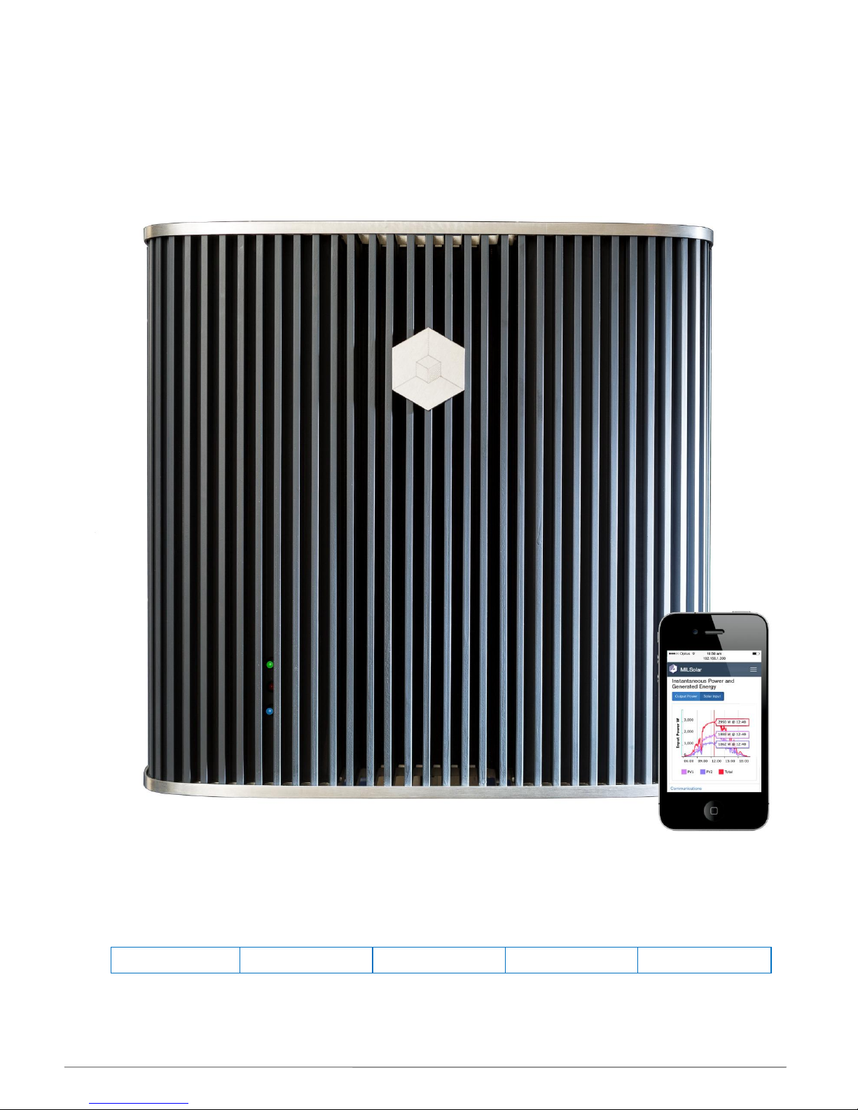
Eclipse series Solar Inverter
User Manual
Applicable Models
This manual covers the following MIL-Solar inverter base models:
Eclipse 3000-II
Eclipse 4000-II
Eclipse 4600-II
Eclipse 4950-II
Eclipse 5000-II
Including optional MyPower and Export Limited models.

MIL-Solar Eclipse series Installation manual V2_2 Page 2 of 24
INTRODUCTION
Congratulations on choosing to install a MIL-Solar, Eclipse series solar power Inverter.
This manual provides information on how to install and operate your product as well as tips
on how to maximise the performance you achieve from the unit.
Key features of the Eclipse inverter series include:
• Wide operating Solar range – maximum operating period from ‘first on’ to ‘last off’
time.
• Network ready. Built-in WiFi as standard for web based PV system monitoring &
reporting.
• High efficiency conversion of Solar input power.
• Maximum power point tracking for optimizing PV panel output. (Dual, independent
inputs on selected models)
• Built in Solar system safety and protection systems to isolate earth leakage and
wiring faults
• Integrated, lockable, mounting arrangement.
• Low solar voltage range starting at 120V, early ON time for maximum generation
period.
• 7 year warranty included as standard, upgradeable to 10 years.
• Front mounted heat sink. Allows more airflow, easy care and cleaning from nesting
insects such as wasps, and other such environmental build up.
Updates to this manual
MIL-Solar reserves the right to revise this document and to make changes to the content from time to time without obligation to
give prior notification of any such changes.
Please check with your Installation Company or the MIL-Solar website for the latest information.

MIL-Solar Eclipse series Installation manual V2_2 Page 3 of 24
Table of Contents
Introduction ..................................................................................................................................... 2
About this manual ........................................................................................................................... 4
Definitions ..........................................................................................................................................................4
Symbols .............................................................................................................................................................4
Inverter specifications .......................................................................................................................................4
Overview of Eclipse features .......................................................................................................... 5
Front view and connections ..............................................................................................................................5
Status indicators ................................................................................................................................................5
Serial Number ...................................................................................................................................................5
Web browser display .........................................................................................................................................6
Inverter display on Web browser ................................................................................................................... 6
Interpreting the Status indicators (LEDs) ..........................................................................................................7
Communications Status indicator - BLUE .........................................................................................................7
Installing the Eclipse Inverter ......................................................................................................... 8
Safety instructions .............................................................................................................................................8
Selecting the Mounting Location .......................................................................................................................8
Wifi access .................................................................................................................................................... 8
General Inverter Settings ..................................................................................................................................9
Date – Time ................................................................................................................................................... 9
Inverter Name ................................................................................................................................................ 9
Inverter Operation ......................................................................................................................... 10
Normal Power up and Grid connection .......................................................................................................... 10
Low or no solar power input ........................................................................................................................... 11
Transient supply events ................................................................................................................................. 11
Networking .................................................................................................................................... 12
Connecting with a local device ....................................................................................................................... 12
WiFi connection to a home/office network ..................................................................................................... 15
Connecting the Inverter to a Network.......................................................................................................... 15
Accessing the Inverter via your Network ..................................................................................................... 15
Status when Network is connected ............................................................................................................. 16
Changes to your Network or WiFi router ..................................................................................................... 16
Trouble shooting ........................................................................................................................... 17
Alerts .............................................................................................................................................................. 17
Low or no PV Solar input - NIGHT .............................................................................................................. 17
Grid Disturbance ......................................................................................................................................... 17
No AC mains - Solar Power available ......................................................................................................... 18
No AC mains and no Solar Panel power .................................................................................................... 18
Initialisation disruption - No AC mains ........................................................................................................ 19
PV system monitoring – “Array Isolation” .................................................................................................... 19
Alarms ............................................................................................................................................................ 20
AC - Wiring Fault ......................................................................................................................................... 20
RCD - “Earth Leakage” ............................................................................................................................... 20
PV Panel Wiring or Isolation Fault .............................................................................................................. 21
Maintenance ................................................................................................................................ .. 22
General routine ............................................................................................................................................... 22
Build up from nesting Insects ......................................................................................................................... 22
Warranty ........................................................................................................................................ 23
Warranty Terms - overview ............................................................................................................................ 23
Documentation ............................................................................................................................................... 23
Addendum ..................................................................................................................................... 24
Browser compatibility ..................................................................................................................................... 24
MIL-Solar Eclipse series Installation manual V2_2 Page 4 of 24
ABOUT THIS MANUAL
Definitions
Inverter For the purposes of this manual, Inverter specifically means a Grid connected Solar
Inverter. The Inverter is a device used to convert DC power from photo voltaic solar
cells to AC power for injection into a power grid.
Mains or Grid The public mains network of electricity lines to which all categories of consumers are
connected and as operated by a supply or distribution company.
When Solar Inverters are installed on a domestic or commercial site, they are
connected to this mains grid for the purpose of supplying electrical energy back into the
grid.
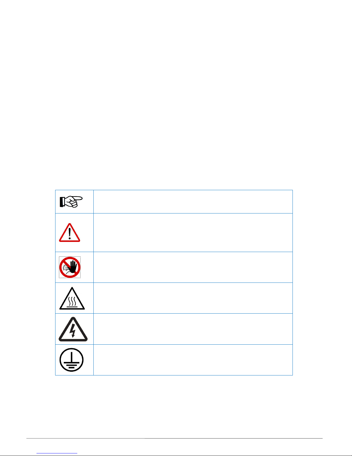
Symbols
Special symbols used throughout this manual.
Inverter specifications
Detailed technical information and specifications for the Eclipse inverter models are detailed in the
datasheet: “ECLIPSE 3000 / 3600 / 4200 / 5000 Solar Inverter specification sheet”
NOTICE
Attention - notes and helpful hints on improving performance.
CAUTION
Indicates a hazardous situation which, if not avoided, could result in minor or
moderate injury and/or damage or failure of the Inverter.
DANGER
Indicates a hazardous situation which, if not avoided, could result in death or
serious injury or potential fire risk.
HOT SURFACES
The top plate and upper surfaces of the Inverter can become hot when operating
at full power on days of high ambient temperature.
ELECTRICAL HAZARD
Do not attempt to open or access internal Inverter components. DO NOT
interfere with the electrical wiring or connections to the Inverter.
CLASS I
Regulatory statement. The Inverter is classified as protective class I.
MIL-Solar Eclipse series Installation manual V2_2 Page 5 of 24
OVERVIEW OF ECLIPSE FEATURES
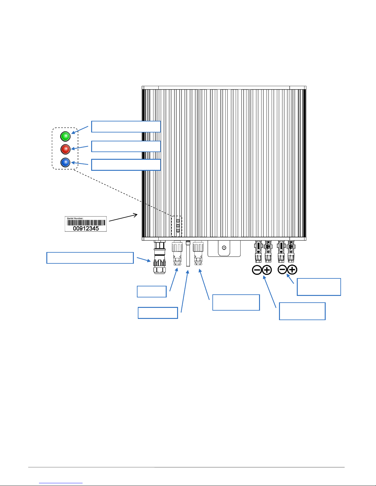
Front view and connections
Status indicators
The Eclipse inverter has a discrete set of three LED indicators for displaying information about the current
state of operation. These indicators have different colours associated with their function.
For further details, refer to relevant sections on normal Eclipse operation and communications, and alerts and
alarms later in this manual.
Serial Number
Your MIL-Solar Eclipse Inverter has been given a unique serial number at time of manufacture. This serial
number is required for registering your equipment for electrical installation and for any warranty or service
claims.
The serial number is displayed on a label located on the lower face of the inverter near the mains connection.
GREEN – AC Operation
RED – PV & Status
BLUE- Communications
Mains connection to Isolator
WiFi aerial
PV connection
MPPT 1
PV connection
MPPT 2
Serial Number
Status Indicators
ALARM
MyPower Meter
MIL-Solar Eclipse series Installation manual V2_2 Page 6 of 24
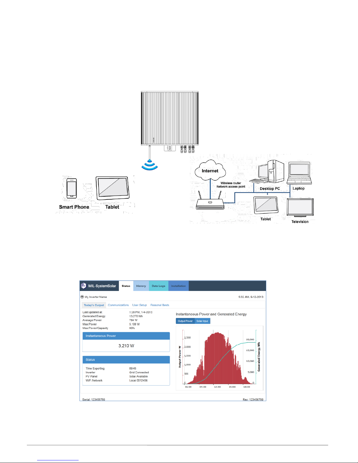
Web browser display
If you have a portable device such as an iPhone or tablet, you can use the standard web browser that
is installed on your device to access and present the Eclipse Inverter display via a WiFi connection.
Equally, the Eclipse Inverter can be connected with a home/office network via WiFi enabling any
computer or device connected to the network to access the Inverter display again utilising a standard
web browser.
For details on how to set up the Inverter display on a web browser refer to the section titled
Networking on page 12.
Inverter display on Web browser
Example Inverter web browser display on a WiFi connected device.
The Inverter display will operate with the latest versions of most common browsers. Refer the
Addendum at the end of this manual for summary list of compatible browsers and devices.
MIL-Solar Eclipse series Installation manual V2_2 Page 7 of 24
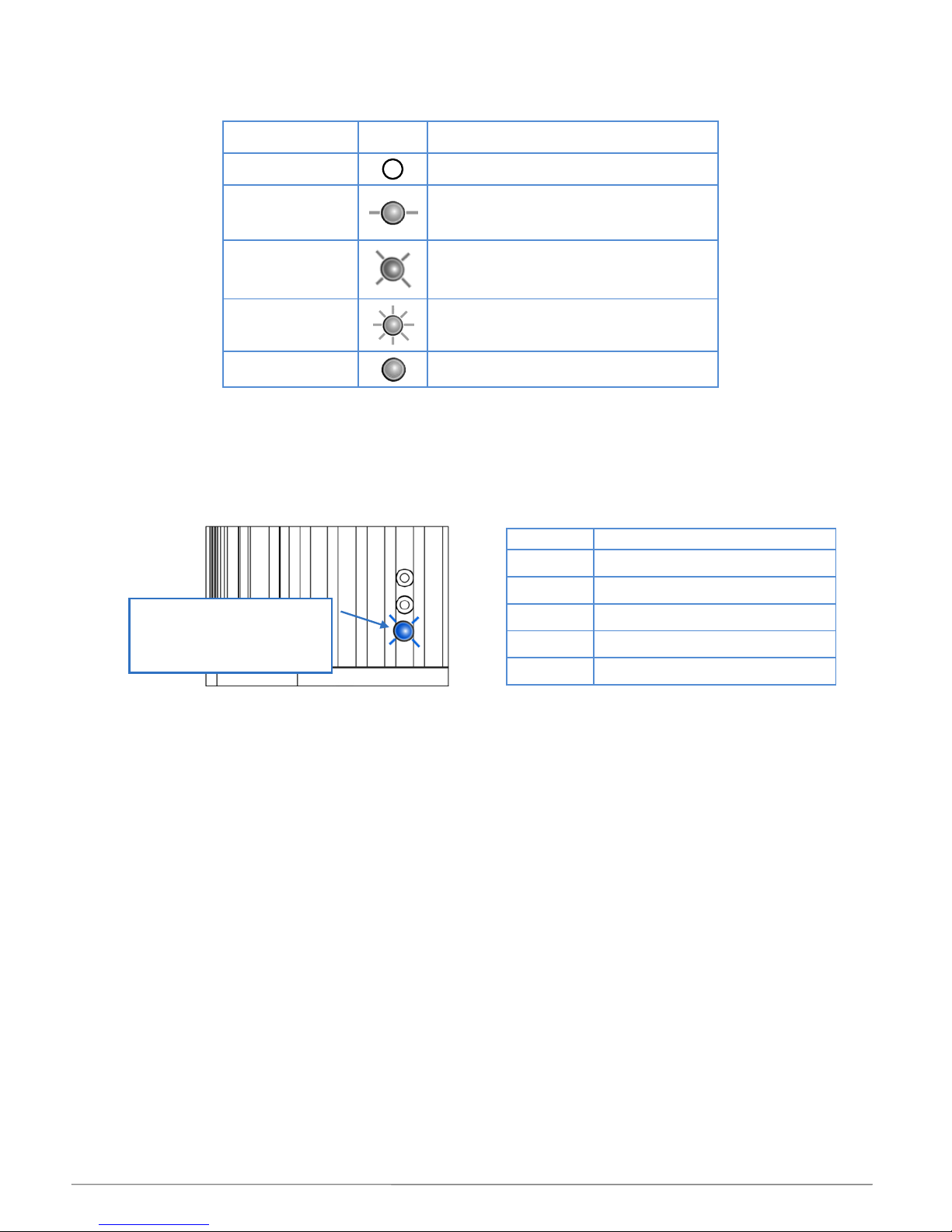
Interpreting the Status indicators (LEDs)
Description used
in this Manual
Symbol
Meaning
OFF
Not illuminated, Not flashing
SLOW
Flashing – once every few seconds
MEDIUM
Flashing – once every second
FAST
Flashing – multiple times per second
Constant
Constantly illuminated, Not flashing
Communications Status indicator - BLUE
The lower blue Status indicator is reserved for WiFi communications information.
It continually reports the status of the communications independently of the other Status indicators.
BLUE
Communications Status
OFF
No communications
SLOW
WiFi connected to network
MEDIUM
FAST
Data currently being transferred
Constant
‘Local’ WiFi mode
BLUE - Communications
Networked WiFi status
MIL-Solar Eclipse series Installation manual V2_2 Page 8 of 24
INSTALLING THE ECLIPSE INVERTER
Safety instructions
Selecting the Mounting Location
When selecting where to install your Eclipse inverter, you must consider and address all of the following points:
Air circulation
Solar Inverters generate heat when operating. They must only be installed in areas
with adequate, natural, free flowing ventilation.
Vertical orientation
The Inverter must be mounted in a vertical orientation to ensure proper cooling.
The end of the housing with the connection points must always point downwards.
Do not mount tilted at an angle to the vertical. Do not mount horizontally.
Direct Sunlight
Do not expose the inverter to direct sunlight to avoid power reduction due to excessive
heating. Optimal operating performance is achieved when the ambient is below 40o C
Shielded location
The Inverter can be located on a building in an outdoor location but should be
mounted in a position that is sheltered from direct weather such as rain and hail.
Wall mounting
requirements
The mounting method and location must be suitable for the inverter's weight and
dimensions and it must be mounted on a solid surface.
(Refer “ Error! Reference source not found.” section on page Error! Bookmark not
defined. for mounting instructions)
Access
Access to the Inverter, and especially any associated isolating switches, must me in
accordance with the specific requirements of the relevant AUS/NZ standards.
The mounting location must at all times be clear and have safe access without the use
of additional aids such as ladders or lifting platforms.
User Visibility
Mount the Inverter at a height, and in such a position that visibility can not be blocked
to allow the operating status LEDs to be seen at all times.
Noise
The inverter can make high pitch noises when in use, which may be perceived as a
nuisance in a living or sleeping area.
Do not mount the unit on plasterboard walls or similar to avoid audible vibrations.
Location regards
other equipment
The minimum horizontal clearance distances to walls and other objects to ensure
sufficient air circulation is achieved for heat dissipation is 100 mm.
Special consideration must be given where multiple Inverters are installed in the same
area. As a minimum, all clearance distances are additive.
DO NOT mount Inverters above each other or other heat generating equipment.
Wifi access
If the Eclipse inverter’s WiFi connection is to be used continually for network access then consideration
must be given to any metal structures near or around the inverter which can affect the WiFi signal.
DANGER
Danger to life and property.
Breach of Government legislation.
Voiding of Warranty.
All electrical installation and commissioning work undertaken on the inverter, and the related connections to isolators,
photovoltaic panels and house wiring systems must only be carried out by suitably qualified and licensed personnel.
CAUTION - Overheating
NEVER store or place objects or boxes on top of the Inverter.
DO NOT install in a position where debris such as leaves can accumulate on it.

MIL-Solar Eclipse series Installation manual V2_2 Page 9 of 24
General Inverter Settings
Date – Time
To ensure all data records that are automatically
logged by the Inverter are referenced correctly, the
Inverter must have the correct Date and Time.
The Date/Time can be verified and/or set by accessing
the [User Setup] tab under the Status menu.
Inverter Name
The Eclipse Inverter can be given a unique name as
determined by the User. This personalised ‘naming’ can
be particularly useful where:
• The User or the Installation Company wishes to
regularly access data from the inverter over the
internet using a local network connection.
Choosing your own name can make it easy to
identify.
• Automatic uploading of data to PVOutput is to be
enabled. The PVOutput site uses the Inverter
name for identification of your system.
Inverter settings such as Date/Time can be set in advance prior to installation on site.
Settings will be retained for a minimum of 10 days without power.
NOW
Can be selected to fill the Date/Time field as per
the current values in your device.
Submit
Any changes made to values on this page must
be submitted before taking effect in the Inverter.

MIL-Solar Eclipse series Installation manual V2_2 Page 10 of 24
INVERTER OPERATION
Normal Power up and Grid connection
The Inverter is powered up by switching ON the AC Isolator switch installed beside the Inverter or in the
adjacent meter box.
When power is ON at the AC Isolator, the Inverter initially caries out a range of self tests.
It then waits for Solar power to be available from the PV panels.
When there is sufficient Solar power available for the Inverter to begin generation, the Inverter will perform a
60 second count down sequence before connecting, or reconnecting, to the grid.
Once connected to the grid, the status display of the Inverter will revert to the normal running condition.
Status
Time Exporting
WiFi network
Inverter
PV Panel
00:00
Solar Generating
Solar available
Local 0012456
GREEN Status.
Constant.
Normal operation
Status
Time Exporting
WiFi network
Inverter
PV Panel
00:00
Connecting 58 secs
Solar available
Local 0012456
GREEN Status.
Flashes at 1 second
rate for 60 seconds
GREEN Status.
Flashes at slow rate
Status
Time Exporting
WiFi network
Inverter
PV Panel
00:00
AC ON – Low solar
Solar available
Local 0012456
RED Status.
Flashes briefly at a Fast rate
Status
Time Exporting
WiFi network
Inverter
PV Panel
00:00
AC ON - Initialising
Solar available
Local 0012456

MIL-Solar Eclipse series Installation manual V2_2 Page 11 of 24
Low or no solar power input
If there is little or no Solar input, the Inverter will not connect to the grid.
Transient supply events
There are conditions and transient events that can occur on the mains supply to your home/office that will be
reported on your Eclipse Inverter.
These events can occur from time to time on the mains supply and the Inverter is programmed to
automatically deal with these conditions. The status of the response will be shown only while it persists and
will be cleared when the Inverter returns to normal operation.
Status display examples
AC - Over Voltage
AC - Under Voltage
AC - Over Frequency
AC - Under Frequency
Loss of synchronisation
A review of any such events can be done by analysing the event log recorded internally by the Inverter.
You do not need to do anything when such status events are shown.
The Eclipse Inverter will automatically return to normal operation when conditions allow it to.
Status
Time Exporting
WiFi network
Inverter
PV Panel
00:00
AC ON – low Solar
Solar available
Local 0012456
GREEN Status.
Continues to flash at
slow rate
RED
Flashes at slow rate.
Automatically restarts.

MIL-Solar Eclipse series Installation manual V2_2 Page 12 of 24
NETWORKING
The MIL-Solar Eclipse Inverter comes standard with WiFi capability enabling them to be connected with a wide
range of devices and home/office networks. This networking capability provides a more comprehensive user
display including the ability to graphically display the Inverter performance as well as providing the means to
recall and display historic performance details.
The WiFi connection to the Inverter can be made in two ways:
Connection to ‘Local’ device
Used for Installation and Configuration and thereafter as required.
Connection to home network and the internet
Required when continual monitoring and logging over Internet is required.
Connecting with a local mobile device
On power up, the Inverter will adopt a local WiFi mode where it acts as a direct wireless access point.
This enables any device such as an iPhone, android, ipad, tablet etc. to be connected with the Inverter and
used for setting up and commissioning of the system.
Even if the Inverter is later configured to operate with a home/office network, it will always return to this local
access state for a period of 5 minutes immediately after being powered up.
To initiate direct connection to a local device, first turn OFF both the AC isolator and the DC
Solar isolators.
When the AC is switched ON - the Inverter will initially go into a WiFi mode where it looks for local
devices to connect with.

MIL-Solar Eclipse series Installation manual V2_2 Page 13 of 24
Eclipse 5000 II…..SN
Eclipse 5000 II…..SN
WiFi Settings
On your phone/tablet, go into Settings
Turn ON WiFi and search for available Networks.
The Eclipse Inverter will be identified by the name
“Eclipse” followed by the model and serial number
for the Inverter.
Eg: Eclipse 5000 II p SN140022
Check that the serial number is the one for this
Inverter (and not that for another nearby unit)
Join to this Eclipse network by tapping on the
selection.
Confirm that the Eclipse Inverter has connected to your
phone or tablet.
Depending on your mobile Device, this may be shown as
a tick , or by the phrase “CONNECTED” or similar.

MIL-Solar Eclipse series Installation manual V2_2 Page 14 of 24
Display on a Browser
Having confirmed connection on the mobile device,
open a Browser on your Phone/Tablet.
E.g. Chrome, Safari, Internet Explorer
In the address bar window at the top of the Browser
type in the IP address
192.168.1.25
The home Status page should then be displayed.
Having connected your mobile device to the Inverter, your Browser can then be used to navigate
the various menus and functions.
This includes monitoring performance as well as accessing various setup and configuration pages.
Local WiFi - Continuous
The WiFi connection LED on the Eclipse Inverter will be constant (not flashing) when the Inverter is in
local WiFi connection mode.
The Inverter will remain in Local WiFi mode if it has not been set up for a WLAN connection.
The Inverter will remain in Local WiFi mode even when a connected device (such as a mobile) goes
out of range. A mobile device returning to the WiFi connection range will be able to simply reconnect
when set up to do so.
Local WiFi connection mode will automatically time out after 5 min if the Inverter has been
previously configured for a WiFi router access point.
The Inverter will CONTINUOUSLY attempt to reconnect with the configured WLAN network after
exiting Local WiFi mode.
Status
Time Exporting
WiFi network
Inverter
PV Panel
00:00
Solar Generating
Solar available
Eclipse 140068
BLUE - Communications
Constant
Local WiFi mode

MIL-Solar Eclipse series Installation manual V2_2 Page 15 of 24
WiFi connection to a home/office network
For connecting with a home/office network via a wireless access point.
First connect a device in Local WiFi mode (refer page 12 for details) to configure the Inverter
for networking with a WiFi router access point.
Connecting the Inverter to a Network
On the STATUS page, locate and select the “Communications” tab.
On the COMMUNICATIONS page, select SCAN to initiate the search and detection of Networks within
the vicinity of the Inverter.
Select CONNECT beside your network name.
Do you know your Network Password?
If your network is password secured, you will be asked to enter this password as part of the
connection process.
Follow the instructions displayed on your device for completing the Network connection.
Accessing the Inverter via your Network
Use any browser such as Internet Explorer, Safari or Chrome on a PC or laptop connected to your
network to access the home page of the Inverter.
The Eclipse Inverter home Status page should now be displayed in your Browser.
If the address “eclipseinverter” does not work then you may have to key the specific IP
address for the Inverter into the Browser. Eg: http:\192.xxx.x.xxx
The actual IP address for the Inverter is assigned by your home network router or computer.
You need to access the allocation information on the router to determine the IP address that
it has given to the Inverter.
The name of your
home/office network
should appear in list.
Communications
Type:
http://eclipseinverter
into the address bar. Enter or Go
http://eclipseinverter

MIL-Solar Eclipse series Installation manual V2_2 Page 16 of 24
Status when Network is connected
Changes to your Network or WiFi router
Network router address change.
If your network wireless access point router is reset or changes it’s network identification details, then
the network connection may have to be set up again in the Inverter.
Network setup is carried out in Local WiFi access mode. Refer page 12.
Status
Time Exporting
WiFi network
Inverter
PV Panel
00:00
Solar Generating
Solar available
My Network Name
BLUE - Communications
Slow Flashing
Networked WiFi mode

MIL-Solar Eclipse series Installation manual V2_2 Page 17 of 24
TROUBLE SHOOTING
Alerts
Low or no PV Solar input - NIGHT
The Eclipse Inverter continually monitors the solar input from the PV panels.
This status is displayed whenever there is insufficient solar energy for the Inverter to operate.
This is the NORMAL status if there is no sun or very low solar input.
Grid Disturbance
The Eclipse Inverter continually monitors the mains supply while it is operating.
If the mains supply goes outside of set limits for over/under voltage or frequency then it will temporarily
disconnect and display this status.
These are normal transitory occurrences of the mains supply that should only occur infrequently.
If you find they are occurring regularly, then contact your solar system supplier and have them monitor
and review your mains conditions.
You do not need to do anything.
The Inverter will continue to monitor the mains conditions and automatically reconnect when it
returns to normal. This condition is not a fault of the Inverter.
This status will also be displayed if the solar panel isolators are turned OFF.
Check the solar panel switches (DC) and ensure they are all turned “ON”.
Status
Time Exporting
WiFi network
Inverter
PV Panel
00:00
Mains status
Solar available
Local 0012456
RED - Status
Continuous flashing at
medium rate – 1 Second
Examples:
Mains Over Voltage
Mains Under Voltage
Mains Over Frequency
Mains Under Frequency
Status
Time Exporting
WiFi network
Inverter
PV Panel
00:00
AC ON – low Solar
Solar available
Local 0012456
GREEN Status.
Continues to flash at
slow rate

MIL-Solar Eclipse series Installation manual V2_2 Page 18 of 24
No AC mains - Solar Power available
The Inverter is being powered by the PV panels. It has detected that there is no AC mains.
AC mains OFF
Check AC Isolator switch adjacent to the Inverter and/or the circuit breaker in the
Switchboard.
No AC mains and no Solar Panel power
The Inverter will operate and display status when either AC – mains power is available OR there is
power available from the PV panels.
If there is no LED display what so ever, then there must be no power available from either the AC
(mains) or DC (Solar Panels)
No Power supply.
Check Isolator switches and/or circuit breaker.
Status
Time Exporting
WiFi network
Inverter
PV Panel
00:00
AC OFF
LOW SOLAR
Local 0012456
GREEN status - OFF
and RED status - OFF
NOT constant
NOT flashing
Note: Status Display
The browser Status Display can not be updated
by the Inverter when there is no power.
It will not show current information.
Status
Time Exporting
WiFi network
Inverter
PV Panel
00:00
AC OFF
Solar Available
Local 0012456
GREEN Status - OFF
RED - Status
Continuous flashing at
slow rate

MIL-Solar Eclipse series Installation manual V2_2 Page 19 of 24
Initialisation disruption - No AC mains
The Inverter is being powered by the PV panels. It has detected that there is no AC mains.
An initialisation disruption has occurred on start-up.
AC mains is OFF
Check AC Isolator switch adjacent to the Inverter and/or the circuit breaker in the
Switchboard.
Turn OFF the DC and ensure AC power is restored and turned ON.
PV system monitoring – “Array Isolation”
The Eclipse Inverter continually monitors the total solar system installation including the PV panel and
PV panel wiring.
If the Inverter sees that PV panel isolation resistance have gone outside of set limits then it will
disconnect from the Grid and continue to monitor the conditions.
The ALARM output will be asserted.
These may be brief, transitory occurrences. If you find they are occurring regularly, then contact your
solar system supplier and have them monitor and review your mains conditions.
The Inverter will normally continue to monitor the conditions and automatically reconnect
when it returns to normal.
This may not occur until the next day in some circumstances.
Fault does not clear
If such a fault indication continues to persist, including when the AC power is turned
OFF/ON, then there may be an issue with your solar system installation or the Inverter itself.
Contact your installation company for a service technician to inspect.
Status
Time Exporting
WiFi network
Inverter
PV Panel
00:00
AC ON
PV status
Local 0012456
RED - Status
Flashing at Fast rate
Examples:
PV 2 Over Current
DC Input fault
Array Isolation fault
GREEN - Status
Flash at SLOW rate
Status
Time Exporting
WiFi network
Inverter
PV Panel
00:00
AC OFF
Solar Available
Local 0012456
GREEN Status - OFF
RED - Status
Continues to flash at
FAST rate

MIL-Solar Eclipse series Installation manual V2_2 Page 20 of 24
Alarms
AC - Wiring Fault
The Eclipse Inverter has determined that there is a fault in the AC or DC connections to the Inverter.
Such faults will be reported when:
The photovoltaic panels or DC connection to the Inverter are incorrectly wired
The AC mains or Earthing is incorrectly wired.
This is an installation wiring fault.
The Eclipse Inverter will not attempt to start under such a fault condition.
DO NOT OPERATE THE INVERTER
An Array Isolation fault can not be reset or cleared by the user.
Contact your Installation company or a qualified electrical service person to check the
PV panels and wiring.
RCD - “Earth Leakage”
The Eclipse Inverter has inbuilt earth leakage detection circuits to detect potentially serious earth faults
and to shut down and isolate the Inverter operation. Such faults may occur in:
The photovoltaic panels or their wiring
The AC and earth wiring to the Inverter.
A possible earth leakage fault in these circuits is potentially serious. As a safety
feature, the Eclipse Inverter will not attempt to start under such a fault condition.
The ALARM output will be asserted
DO NOT OPERATE THE INVERTER
An earth leakage fault can not be reset or cleared by the user.
Contact your Installation company or a qualified electrical service person to check the
PV panels and wiring.
Status
Time Exporting
WiFi network
Inverter
PV Panel
00:00
RCD – Earth fault
Solar available
Local 0012456
RCD - Fault.
GREEN - flashing at Fast
rate.
RED - flashing at Slow
rate.
Status
Time Exporting
WiFi network
Inverter
PV Panel
00:00
AC Mis-wired
PV 2 Mis-wired
Local 0012456
Mis-Wired.
RED & GREEN
Flashing at fast rate
Examples:
PV 1 Mis-wired
PV 2 Mis-wired
Example:
AC Mis-wired

MIL-Solar Eclipse series Installation manual V2_2 Page 21 of 24
PV Panel Wiring or Isolation Fault
The Eclipse Inverter has determined that there is a fault in the DC connections to the Inverter.
Such faults will be reported when:
The photovoltaic panels or DC connection to the Inverter are incorrectly wired
The photovoltaic panels or wiring system have excess leakage to earth.
This is an installation wiring fault.
The Eclipse Inverter will not attempt to start under such a fault condition.
The ALARM output will be asserted
DO NOT OPERATE THE INVERTER
A PV Panel earth leakage fault can not be reset or cleared by the user.
Contact your Installation company or a qualified electrical service person to check the
PV panels and wiring.
Status
Time Exporting
WiFi network
Inverter
PV Panel
00:00
AC ON
PV 2 Mis-wired
Local 0012456
PV Panel Fault
GREEN – slow flash
RED - Flashing at fast rate
Examples:
Array Isolation fault
PV 1 Over Voltage
PV 2 Over Voltage

MIL-Solar Eclipse series Installation manual V2_2 Page 22 of 24
MAINTENANCE
General routine
The MIL-Solar Eclipse inverter is designed to require very little maintenance.
It is recommended to routinely:
Check that nothing has been placed on the top surface of the Inverter.
Check that nothing has changed in the installation surrounds that could potentially impact ventilation
to the Inverter.
Check there is no build up in the cooling fins that could be compromising the convection air flow. This
will cause the Inverter to run at elevated temperatures and impact its generation performance.
Build up from nesting Insects
The Eclipse series of inverters has been designed with forward facing cooling fins so that any build up in the
fins that may occur from nesting insects such as mud wasps can be easily removed.
1. Ensure that adequate personal protection is used to prevent any risks that may arise from the
insects and/or their bites or stings.
2. Turn off the AC and DC (solar) isolators
3. Scrape out any build up from the cooling fins using a thin, stiff tool such as a screw driver.
Give special attention and care to not damaging or scratching the three status indicators. If in
doubt, do not clean in this channel.
4. Remove all tools.
5. Turn back ON the AC and DC (solar) isolators
Chemical cleaners
Do not use chemical cleaners or solvents on the Eclipse inverter or the related solar system
wiring or any Isolator switches.

MIL-Solar Eclipse series Installation manual V2_2 Page 23 of 24
WARRANTY
All MIL-Solar inverters must only be installed by a qualified electrician in accordance with the requirements of
AS3000 and those particularly pertaining to AS 4777.1 “Grid connection of energy systems via inverters Installation requirements” and be registered with your relevant state government electrical authority.
All MIL-Solar inverters must be installed in accordance with the published Instalation details and operated and
maintained in accordance with the instructions detailed in this manual.
Warranty Terms - overview
All MIL-Solar inverters carry a standard 5 year factory warranty.
An option to extend this period to 10 years is available – for pricing and application, please contact your
Installation Company or visit www.MilSystemSolar.solar
All inverters must be registered within 30 days of installation with the accompanying electrical
installation certificate information. Factory warranty does not apply to unregistered inverters.
Any warranty claims are determined against the installation address, the installation procedure and
compliance with our installation registration process and minimum guidelines.
The MIL-Solar warranty covers repair or replacement of parts or full replacement of the inverter during
the warranty period. MIL-Solar, will at its sole discretion elect to carry out repairs at the installed site or
remove the inverter for repair off site or exchange the installed inverter for the same or similar model.
In the case of a full exchange the remainder of the warranty entitlement will be transferred to the
replacement device.
Specific exclusions for liability under the terms and conditions of this Warranty include:
- Damage arising in part, or in full, from mishandling during transport or installation.
- Failure to correctly install or commission the inverter or related wiring.
- Failure to correctly maintain the inverter.
- Unauthorised attempts to modify or repair the inverter.
- Siting of the inverter contrary to the installation guidelines such as in direct rain or inadequate
ventilation.
- Failure to comply with any local regulations.
- Force majeure, including but not limited to, acts of god, lightning strike, PV input overvoltage,
fire and flood.
- Cosmetic shortcomings which do not affect the inverter operation.
- Any claims for consequential losses such as related to direct or indirect damage or
compensation for any loss of profits
All MIL-Solar inverters are designed and certified for specific countries in order to meet that country's
specific legal, certification and safety requirements. Unless the inverter has the correct country safety
and electrical certification, it must not be installed. Any inverter installed in a country or region that is not
specifically nominated on the inverter certification carries no warranty, and such use of the inverter will
be at the customer's sole risk and liability.
Full details of the Warranty terms and conditions and MIL-Solar general terms and conditions of trade
can be found at: www.MilSystemSolar.solar
Documentation
Unless otherwise specifically agreed to in writing, MIL-Solar makes no warranty as to the accuracy,
sufficiency, or suitability of any technical or other information provided in this manual.
MIL-Solar assumes no responsibility or liability for losses, damages, costs or expenses, whatsoever
whether special, direct, indirect, consequential or incidental, which might arise out of the use of this
information.

MIL-Solar Eclipse series Installation manual V2_2 Page 24 of 24
ADDENDUM
Browser compatibility
Browser
Operating System
Compatible versions
Chrome
Windows, OS X, Linux
32.0.1700.102 m or later
Chrome for Android
Android
32.0.1700.99 or later
Firefox
Windows, OS X, Linux
26.0 or later
Opera
Mobile devices
incompatible
Mobile Safari
iOS
iOS 6 or later
Desktop Safari
OS X
Safari 6 or later
Internet Explorer
Windows
IE 9 or later
Android Browser
Android
Android 4.1 or later
For more details and for latest updates, please refer www.MSS.solar/Inverterbrowsers
 Loading...