

M I L - R A M T E C H N O L O G Y
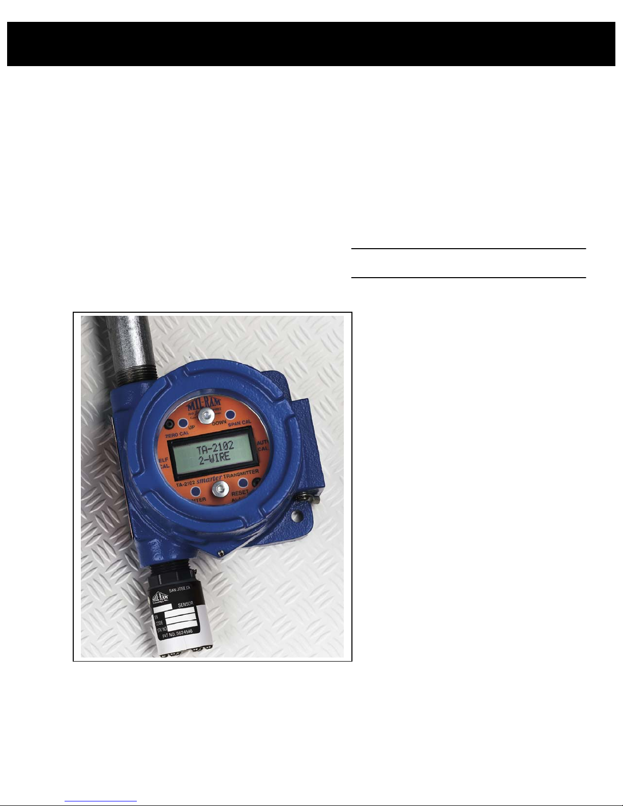
TA-2102
Two Wire Loop Powered
smarter Transmitter
Instruction Manual
Detection Range:
Operating Voltage: 10-30 VDC
Arsine, AsH3 Tungsten Hexafluoride, WF
Phosphine, PH3 Tetrachlorosilane, SiCl4
Diborane, B2H
Hydrazine, N
Silane, SiH
4
6
2H4
Many More Gases
Ammonia, NH3
Boron Trichloride, BCl
Bromine, Br2
Carbon Monoxide, CO
Chlorine, Cl2
Chlorine Dioxide, ClO2
Dichlorosilane, SiH2Cl
Fluorine, F2
Hydrogen Bromide, HBr
Hydrogen Chloride, HCl
Hydrogen Cyanide, HCN
Hydrogen Fluoride, HF
Hydrogen Iodide, HI
Hydrogen Peroxide, H
Hydrogen Sulfide, H
Nitric Acid Vapors, HNO3
Nitrogen Dioxide, NO
Oxygen, O
Ozone, O
Sulfur Dioxide
Silicon Tetrafluoride, SiF
Sulfur Dioxide, SO2
Sulfuric Acid Vapors, H
6
2
3
5423 Central Avenue Suite 1
Mil-Ram Technology, Inc.
2
S
2
3
2
2O2
2SO4
4
no false alarms
Newark, CA 94560
Ph (510) 818-0200
Fax (510) 818-0300
Web: www.mil-ram.com

Table of Contents
I. Description ............................................................................... 1
II. Smarter Features ..................................................................... 1
III. Installation ............................................................................... 2
IV. Transmitter Wiring ................................................................ 4
V. Transmitter Operation........................................................... 5
A. Main Information Mode.................................................... 6
B. Loop Test............................................................................. 9
VI. Diagnostic Messages............................................................. 11
VII. Rain/Splash/RF Shield (optional)....................................... 12
IIX. Sensor Calibration ............................................................... 13
A. Zero Calibration ............................................................ 14
B. Span Calibration ............................................................ 15
IX. Off-Site Sensor Calibration................................................ 16
X. Self-Calibration .................................................................... 17
XI. Remaining Sensor Life........................................................ 17
Installation Drawings
Warranty

I. Description:
The model TA-2102 smarter Transmitter provides remote detection of a specific toxic gas
using Mil-Ram’s patented no false alarms electrochemical sensor technology. The
transmitter is two-wire loop powered and transmits a standard 4-20mA signal. The smarter
transmitter operates on 10-30 VDC.
II. Smarter Features:
• 2-Wire Loop Powered – operates on 10-30 VDC and generates a standard 4-20mA
signal
• Self-Calibration – unattended span calibration adjustments performed every 30 days
based on life curve for sensor
• Auto-Calibration – non-intrusive calibrations using a magnet to activate zero and span
switches located behind glass window of explosion-proof junction box – no mechanical
adjustments required
• LCD Display – 12 character x 2 line display provides meter readings, calculated values
and diagnostic messages
• Life Remaining – sensor life remaining based on calibration history, life curve for sensor
and electrical characteristics of sensor
• Peak Value/15-min. TWA/Number of days since last gas calibration—Transmitter
displays this information on demand
• Loop Test – Output 4/8/12/16/20mA to verify readings and alarms at controller
electronics
• Calibration Mode Alarm Inhibit – during span calibration and for a period of 5 minutes
after calibration, the transmitter outputs 4.0mA
• Diagnostics – continuous diagnostics related to both hardware and software operation
with auto reset of micro-controller in the event of software failure – provide messages
including Replace Sensor, Remaining Sensor Life and Sensor Disconnected
2-Wire Toxic Smarter Transmitter
22May2002 Page 1
III. Installation:
The sensor is provided with ¾’ NPT external threads opposite the sensing end of the device.
The sensor screws into an explosion-proof junction box which houses the smarter
electronics. The sensor/smarter electronics/junction box assembly constitutes the
transmitter.
Install transmitter as follows:
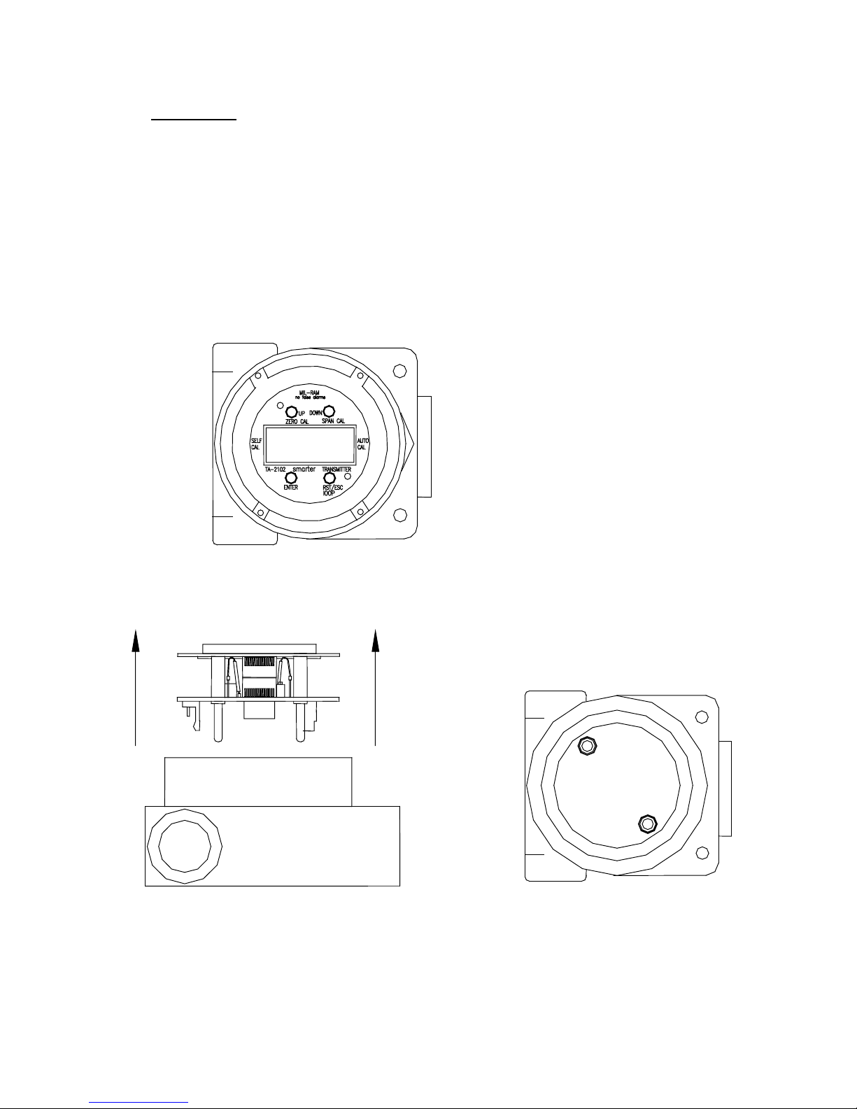
1. Unscrew cover (with glass window) from junction box.
Junction Box with cover/glass
window removed
Removal of LCD display/main circuit
board assembly from junction box
22May2002 Page 2
Junction box with banana
sockets
2. Remove LCD display/main circuit board assembly by pulling up on face plate at two
locations marked PULL (banana jacks secure the assembly in the junction box).
Carefully lift assembly from junction box.
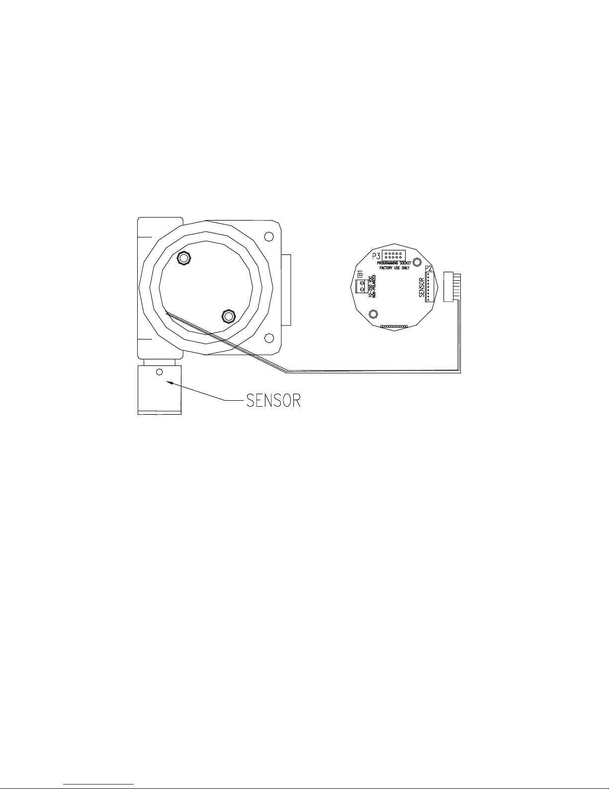
3. Carefully guide brown sensor cable connector through opening in bottom of junction
box. Screw sensor into junction box hand tight. Attach sensor connector to bottom of
main circuit board at 9-pin brown connector marked SENSOR. Seat the sensor
connector fully to lock in place.
4. Install LCD display/main circuit board assembly in junction box by carefully aligning
banana plugs on bottom of main circuit board with sockets in junction box. Gently push
(directly above face-plate screws) until banana plugs seat fully in sockets.
5. Replace cover on junction box.
6. Mount junction box to a vertical surface with the perforated end of the sensor
pointing downward.
Note: It is generally recommended that the sensor be installed at a location as close as
possible to the source of gas.
22May2002 Page 3
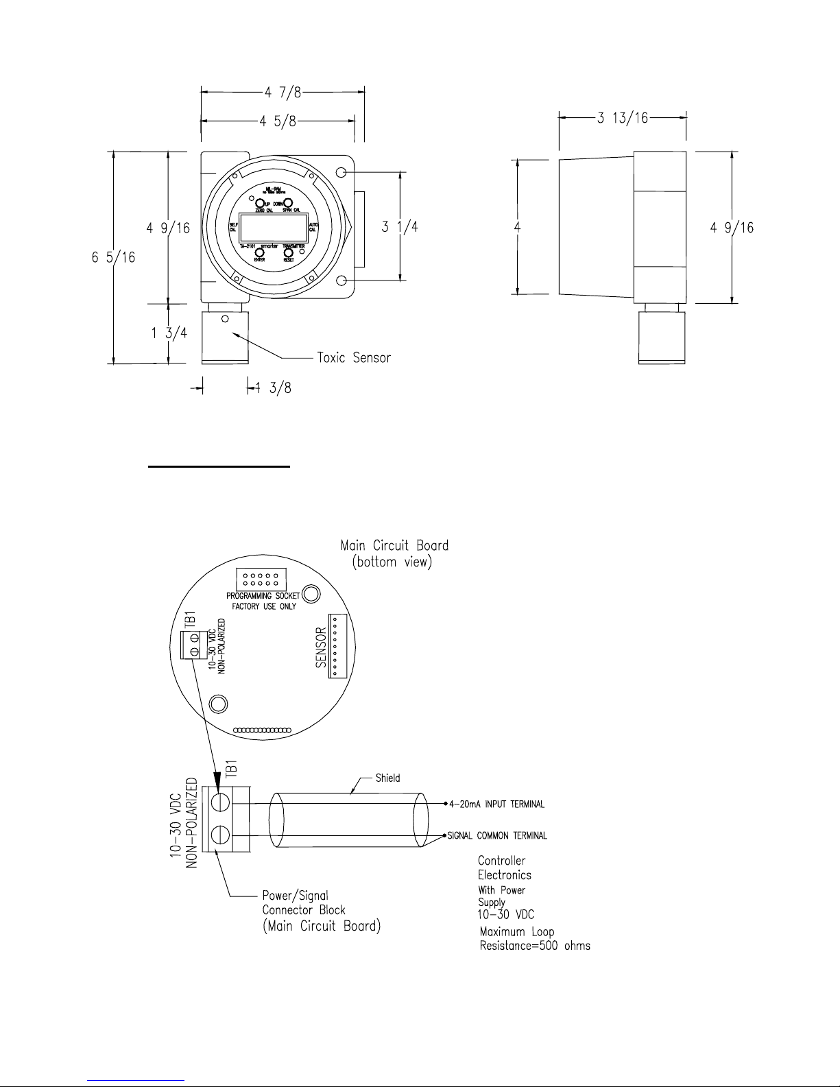
IV. Transmitter Wiring:
The smarter transmitter is 2-wire loop powered and operates on 10-30 VDC. Make
connections as follows:
22May2002 Page 4
Run two wires from the controller 4-20mA Input and signal common to the power/signal
terminals located on the bottom of the main circuit board. The power/signal terminals are
non-polarized.
NOTE: The two power/signal wires must be isolated from other wires and should therefore
be shielded or run in metal conduit to avoid electrical pick-up. If a shield is used it
should run continuously from the controller electronics to the inside of the
transmitter junction box. The shield should be terminated at the controller signal
common but left floating (do not attach to anything) inside the transmitter junction
box to avoid ground loop interference. Apply electrical tape to exposed shield
inside junction box.
The smarter transmitter can be located up to several thousand feet (max. total loop
resistance = 500 ohms) from the controller electronics using 18 AWG standard copper wire.
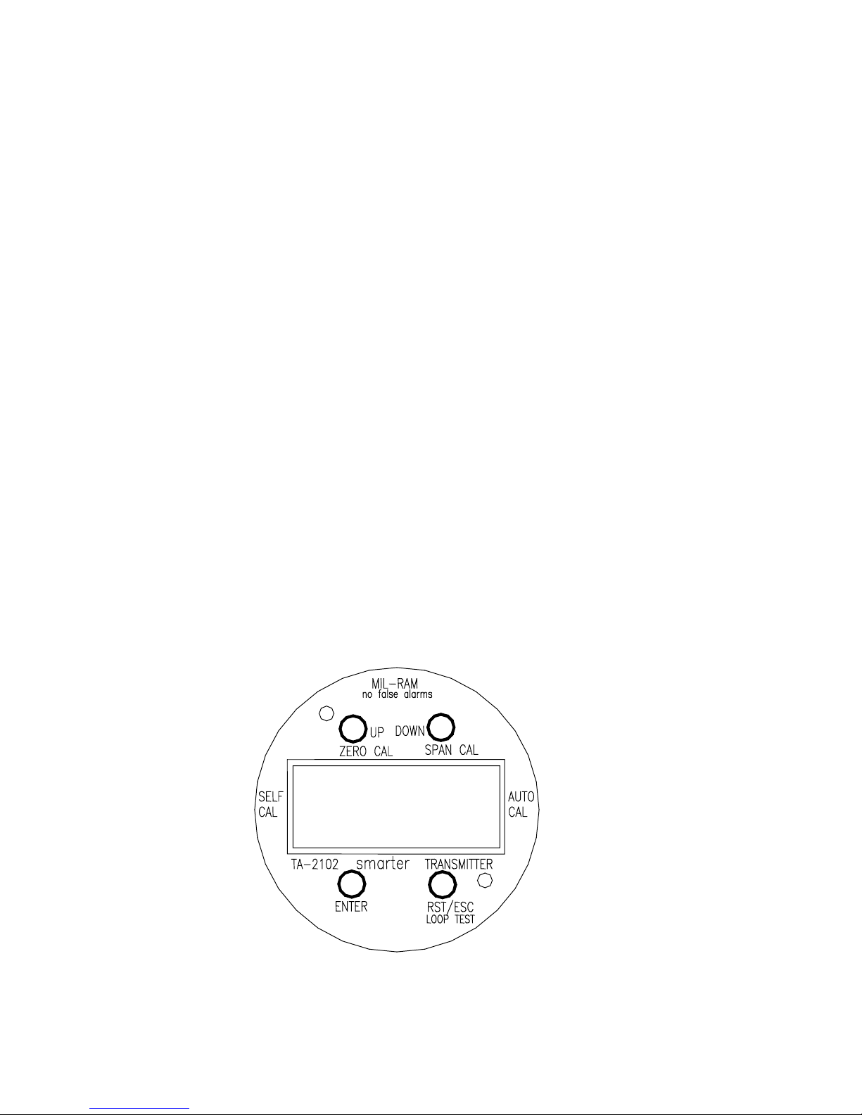
V. Transmitter Operation:
The smarter transmitter provides four magnetic switches to access information, test the
loop and calibrate the toxic sensor. The switches are activated using a magnet held directly
over the switch outside the junction box glass window.
22May2002 Page 5
The switches are designated as follows:
ENTER: A magnetic switch used to enter the main Information Routine to view
Peak Value, Remaining Sensor Life, 15-Min. TWA (Time Weighted
Average) and Ambient Temperature (degrees C). ENTER switch is also
used to escape Loop Test in progress.
UP: A magnetic switch used to enter Zero Calibration mode and increment
span calibration gas concentration. The UP switch is also used to proceed
with the Loop Test.
DOWN: A magnetic switch used to enter Span Calibration mode and decrement
span calibration gas concentration. The DOWN switch is also used to exit
Loop Test before generating any output.
RESET: A magnetic switch used to reset Peak Value and escape Span Calibration
mode without performing calibration.
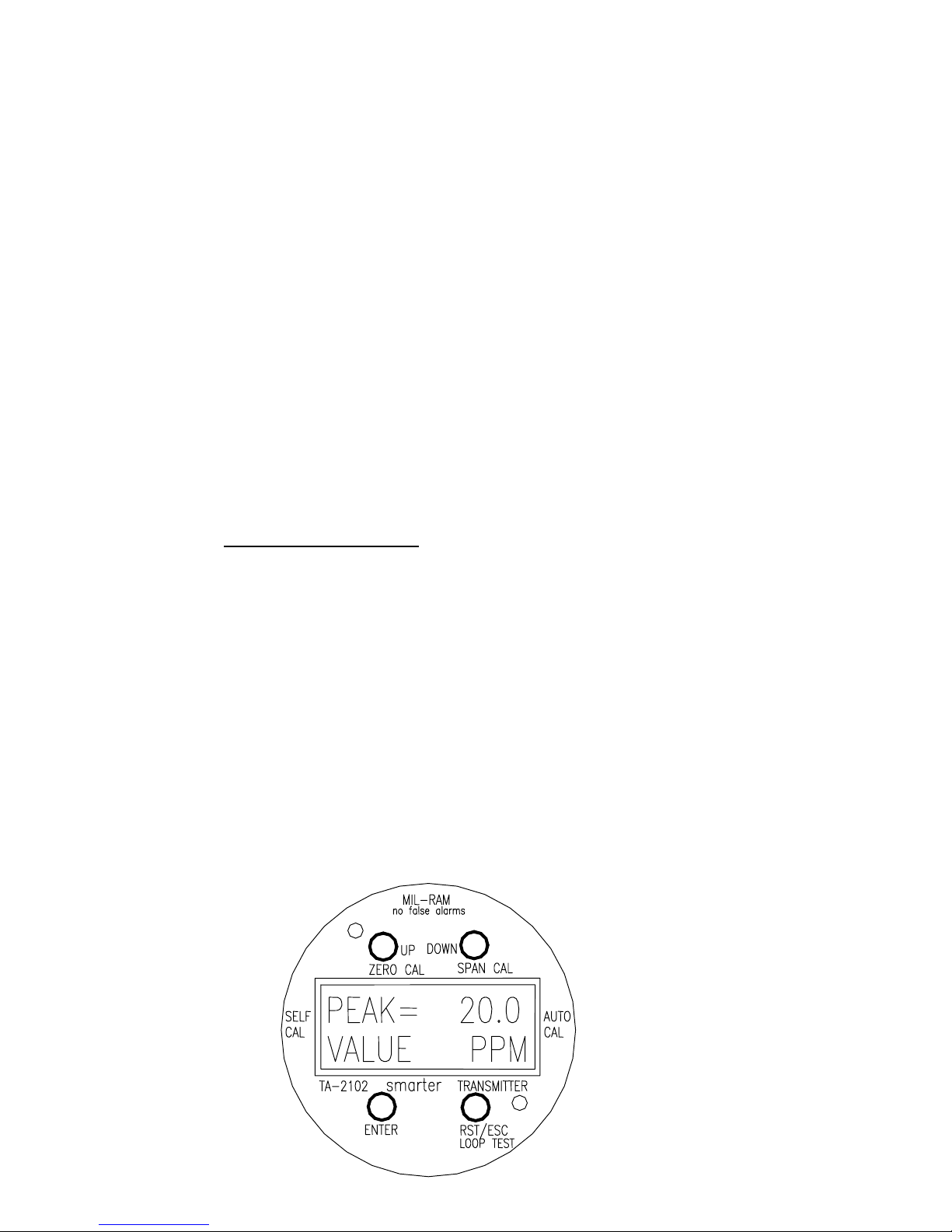
A. Main Information Mode:
The smarter transmitter displays the following parameters when the Information Mode is
entered:
• Peak Value
• Remaining Sensor Life
• 15-Min. TWA (time weighted average)
• Ambient Temperature (degrees C)
Upon entering the Information Mode the LCD display will automatically sequence through
the parameters.
To enter Information Mode, momentarily hold magnet directly over ENTER
switch until LCD display shows the Peak Value
22May2002 Page 6

Note: While Peak Value is displayed, the value can be reset by momentarily holding magnet
directly over RESET switch. A successful reset provides the following message on the
LCD display
Following Peak Value the LCD will automatically proceed to Remaining Sensor
Life
22May2002 Page 7

Next, the LCD will proceed to 15-Min. TWA (Time Weighted Average)
Next, the LCD will proceed to Ambient Temperature
After approximately 5 sec. LCD display will return to normal operating mode to
provide gas readings
22May2002 Page 8

B. Loop Test
The smarter transmitter provides a built-in loop test whereby the transmitter outputs
4/8/12/16/20 mA on demand. The generated output signal can be used to verify
readings/alarms at the Controller electronics and loop integrity.
To enter loop test, hold magnet directly over RESET switch until LCD display
shows
22May2002 Page 9

To escape loop test without generating any output, hold magnet directly over DOWN
switch until LCD display returns to normal operating mode
To proceed with loop test, hold magnet directly over UP switch until LCD display
shows
To increment Signal Output, hold magnet directly over UP switch until LCD
Increments Output Value. When Output reaches 20 mA the next increment will
roll-over to 4 mA.
22May2002
Page 10

To decrement Signal Output, hold magnet directly over DOWN switch until LCD
display decrements Output Value. When Output reaches 4 mA the next decrement
will roll-over to 20 mA.
To exit LOOP TEST, hold magnet directly over ENTER switch to return to normal
operating mode.
VI. Diagnostic Messages:
The LCD display provides the following fault messages during normal operation
Sensor cannot be calibrated—Requires
immediate replacement
Sensor has been disconnected from main
circuit board—transmitter outputs
2.4mA— install sensor as described in
Section III, steps 1-6, above
Relay Definitions:
The 2-Wire smarter Transmitter does not provide local relay outputs. However, external
relays are often used at the controller electronics to provide appropriate alarms at pre-set
alarm points. The following definitions are provided for general information.
Non-latching: when alarm set point is reached and exceeded, relay is activated (open
contacts close and closed contacts open). When gas concentration falls
22May2002 Page 11

below alarm set point, relay automatically resets to original state.
Latching: when alarm set point is reached and exceeded, relay is activated (i.e. open
contacts close and closed contacts open). When gas concentration falls
below alarm set point, relay does not reset to original state. The relay
must be manually reset using a switch.
Energized: Power is normally applied to relay such that normally open contacts are
closed and normally closed contacts are open. When the alarm set point is
reached or exceeded, the relay changes to the power down state.
Non- Energized: Power is normally not applied to relay such that normally open contacts are
open and normally closed contacts are closed. When alarm set point is
reached or exceeded, the relay changes state.
VII. Rain/Splash/RF Shield (Optional)
A black anodized aluminum shield offers protection to the sensor from rain, splashing,
radio frequency (RF) and mechanical shock.
The upper portion of the housing is provided with internal and external 3/4” NPT threads.
The external threads screw into the explosion-proof junction box which houses the
remote amplifier. The sensor screws into the 3/4” NPT internal threads.
The lower portion of the housing consists of a cylinder with bottom plate; the housing is
perforated to allow gas entry. The cylinder is secured to the upper housing with four set
screws.
Install the shield as follows:
1. Screw upper portion of housing into junction box.
2. Carefully guide brown sensor cable connector through housing
into junction box. Screw sensor into housing hand tight. Attach
sensor connector to bottom of main circuit board at connector
marked SENSOR. Seat the sensor connector fully to lock in place.
22May2002
Page 12

3. Position lower portion of housing (cylinder) around sensor. Push
upper edge of cylinder over upper housing. Tighten four set screws
to secure cylinder.
VIII. SENSOR CALIBRATION:
NOTE: A routine program of calibration should be employed to ensure proper
operation/performance of the sensor and system. Although the sensors are normally
quite stable, it is generally recommended that calibration be performed monthly in
the interest of safety.
Sensor calibration is performed at the smarter transmitter using a gas sample of known
concentration. To calibrate the sensor, follow the steps outlined below.
NOTE: The sensors are factory calibrated with gas prior to delivery. Field calibrations
must be performed with an appropriated gas sample of known concentration.
22May2002 Page 13

A. Zero Calibration:
1. In clean gas-free air, momentarily hold magnet over ZERO CAL switch until LCD
display shows
When zero calibration is complete, the transmitter will return to normal operation to
provide meter readings.
Note: If ambient air is not known to be gas-free, apply zero air (cylinder) using calibration
Cup
22May2002 Page 14

B. Span Calibration:
1. Momentarily hold magnet over SPAN CAL switch until LCD display shows
Note: To exit span calibration mode without performing calibration, momentarily hold
Magnet directly overt RESET switch.
2. Momentarily hold magnet directly over UP or Down switch to increment or
decrement calibration gas concentration. When proper gas concentration is
displayed, hold magnet directly over ENTER switch to advance to next display
22May2002 Page 15

3. Apply span calibration gas of exact concentration shown on LCD display using
calibration cup.
4. When span calibration is complete, the transmitter will return to normal operation to
provide meter readings. Note: during span calibration and for a period of 5 minutes
after calibration, the smarter transmitter outputs 4.0mA to prevent activation of
alarms at the controller electronics.
5. Remove calibration cup and allow sensor to recover. LCD display will show recovery of sensor to zero.
22May2002 Page 16

IX. Off-Site Sensor Calibration:
The smarter transmitter Toxic gas sensors include an EEprom encapsulated inside the
sensor housing. The EEprom retains all set-up parameters (alarm set points, relay
operation/function, etc.) and sensor calibration factors. Therefore, the sensors can be
calibrated in the instrument shop (i.e. off-site) with Mil-Ram Remote Calibration
Electronics (contact factory) and the sensors re-installed in the field without further
calibration. Upon installing the sensors, the field installed transmitter electronics
automatically up-loads the calibration data to properly configure the transmitter.
X. Self-Calibration:
The smarter transmitter provides unattended self-calibration features whereby every 30
days the micro-controller electronics increments the span calibration based on the typical
life curve for the sensor type. When a field calibration is performed with a gas sample of
known concentration, the life curve is re-extrapolated based on actual calibration data.
Note: The self-calibration feature is intended to supplement and not replace a regular
calibration program using a certified gas sample of known concentration. Although
the sensors are normally quite stable, it is generally recommended that calibration be
performed monthly in the interest of safety. Unusually harsh or severe environments may require more frequent calibration checks.
XI. Remaining Sensor Life:
The smarter transmitter determines Remaining Sensor Life based on actual field
calibration data, sensor life curve and specific electrical characteristics of the sensor. The
remaining sensor life is an approximation and does not replace a regular calibration
program using a certified gas sample of known concentration to validate sensor response.
Near the end of sensor service life, the transmitter will indicate Replace Sensor. At that
time the sensor must be replaced with a new sensor to ensure proper calibration.
22May2002 Page 17


MIL-RAM TECHNOLOGY, INC.
TOXIC GAS DETECTION INSTRUMENTS AND SENSORS - WARRANTY
Mil-Ram Technology, Inc., warrants toxic gas alarm equipment manufactured and sold by it to be free
from defects in materials, workmanship, and performance for a period of one year from date of shipment
from Mil-Ram Technology, Inc. Any parts found defective within that period will be repaired or
replaced, at its option, free of charge, f.o.b. factory. This warranty does not apply to items which by
their nature are subject to deterioration or consumption in normal service, and which must be cleaned,
repaired, or replaced on a routine basis. Items included, but not limited to, are:
1. Absorbent cartridges
2. Batteries
3. Filter element
4. Lamp bulbs and fuses
5. Pump diaphragms and valves
6. Sensors - electrochemical sensors for Tox-Array 1000
Portable Monitors are covered by a warranty of 24 months.
7. Sensors - electrochemical sensors for Fixed Systems and Transmitter are
covered by a warranty of 12 months.
Warranty is voided by abuse, including rough handling, mechanical damage, alteration or repair by an
unqualified person and/or procedures not in accordance with the corresponding instruction manuals and
specifications. This warranty indicates the full extent of our liability, and we are not responsible for
removal or replacement costs, local repair costs, transportation costs, or contingent expenses incurred
without our prior written approval.
Mil-Ram Technology, Inc.’s obligation under this warranty shall be limited to repairing or replacing and
returning any product which Mil-Ram Technology, Inc., upon a detailed examination by Mil-Ram
Technology, Inc., shall disclose to have been defective. To receive warranty consideration, all products
must be returned to Mil-Ram Technology, Inc., at its manufacturing facilities with transportation
charges prepaid.
This warranty is expressly in lieu of any and all other warranties and representations, express or implied,
and all other obligations or liabilities on the part of Mil-Ram Technology, Inc., including, but not limited
to, the warranty of fitness for a particular purpose. In no event shall Mil-Ram Technology, Inc., be
liable for direct, incidental, or consequential loss or damage of any kind connected with the use of its
products or failure of its products to function or operate properly.
This warranty covers instruments and parts sold (to users) only by authorized distributors, dealers and
representatives as appointed by Mil-Ram Technology, Inc.
 Loading...