

Page 1

MILPOWER SOURCE
UNINTERRUPTIBLE POWER SOURCE
SINGLE PHASE – 1kW / 2kVA
M110BA-1
MADE IN THE U.S.A
USER’S MANUAL
East Coast
Milpower Source
7 Field Lane, RTE. 106
Belmont, NH 03220
Phone: (603) 267-8865 Fax: (603) 267-7258
West Coast
Hytech Associates
1498 Linda Vista Ave.
Pasadena, CA 91103
Phone: (818) 7964761 Fax: (818) 304-9620
November, 2003
Publication Number: 110BA1UM, REV(B)
Page 2

MILPOWER SOURCE 110BA1UM, REV(B)
110BA1UM, REV(B)
Table of Contents
Page
Safety Instructions .................................................................................................iii
1. General Description.................................................................................................1
1.1 Intended Applications.............................................................................................1
1.2 Functional Overview ...............................................................................................1
2. Setting the Input Voltage Range............................................................................3
3. Installation Instructions..........................................................................................3
4. Front Panel Description..........................................................................................6
4.1 Front Panel: Main Components ............................................................................6
4.2 Front Panel: Indicators and Switches ..................................................................7
5. Rear Panel Description ...........................................................................................8
6. Operation, Controls and Indicators.......................................................................9
6.1 Turning the UPS ON and OFF ................................................................................9
6.2 Visual Indicators......................................................................................................9
6.2.1 Normal Operation ....................................................................................................9
6.2.2 Standby Mode..........................................................................................................9
6.2.3 Input AC Failure.....................................................................................................10
6.2.4 Overload Condition ...............................................................................................10
6.2.5 Over Temperature Condition................................................................................10
6.3 Battery Test............................................................................................................11
7. Taking Care of the Battery....................................................................................11
7.1 Battery Service Life...............................................................................................11
7.2 Replacing the Battery Pack..................................................................................12
8. Communications and Remote Control................................................................13
8.1 Dry Contacts Interface ..........................................................................................13
8.1.1 Option 0 (Standard) Dry Contacts Interface .......................................................13
8.1.2 Option 1 Dry Contacts Interface...........................................................................14
8.2 RS-232 Communication Interface........................................................................15
8.3 Remote ON/OFF Interface…………………………………………………………….15
9. Specifications ........................................................................................................16
List of Figures
Page
Fig. 1 Block Diagram..........................................................................................................2
Fig. 2 Electrical Connections (with Bypass) ...................................................................4
Fig. 3 Electrical Connections (without Bypass)..............................................................5
Fig. 4 Front Panel - Main Components ............................................................................6
Fig. 5 Front Panel - Indicators ..........................................................................................7
Fig. 6 Rear Panel ................................................................................................................8
Fig. 7 Dry Contacts - Option 0.........................................................................................14
Fig. 8 Dry Contacts - Option 1.........................................................................................14
List of Tables
Page
Table 1 Dry Contacts Connector J3 Pin Assignment (Option 0)....................................13
Table 2 Dry Contacts Connector J3 Pin Assignment (Option 1)....................................14
Table 3 RS232 Connector J4 Pin Assignment .................................................................15
ii
Page 3

MILPOWER SOURCE 110BA1UM, REV(B)
IMPORTANT SAFETY INSTRUCTIONS
• The M110BA-1 contains an internal high voltage, high energy power source (96VDC battery) and
large high voltage (340VDC) capacitors.
• The unit should not be tampered with by unauthorized personnel !!!
• Turning off the Input ON/OFF Switch and/or disconnecting the input connector do not
the UPS !!!
• The Power Conditioner output is not switched off by the Input ON/OFF Switch !!!
• The unit should only be plugged into an approved double-pole and fused 20A electrical outlet !!!
(for 230VAC input use 15 AMP fuses).
• The Replaceable Battery Pack of the M110BA-1 (MPS P/N M357380) contains lead-acid batteries.
The Battery Pack should not be opened. It can only be replaced with a new pack (battery cells
cannot be replaced individually).
• Dispose the Battery Pack properly. Careless disposal (such as into a fire) may cause an
explosion. Local regulations may require controlled disposal of lead-acid batteries. Please check
your local regulations before disposal.
turn off
iii
Page 4

MILPOWER SOURCE 110BA1UM, REV(B)
1. General Description
1.1 Intended Applications
The M110BA-1 is a high quality, rugged, 1kW / 2KVA, 19” rack-mounted Un-interruptible Power
Source (UPS). In addition to full compliance with all the requirements of MIL-STD-1399 (Section
300), the M110BA-1 is specifically designed to meet the harsh military shipboard environment. The
high reliability and ruggedness of the M110BA-1 make it an excellent choice not only for military
shipboard applications, but for critical shore-based applications as well.
1.2 Functional Overview
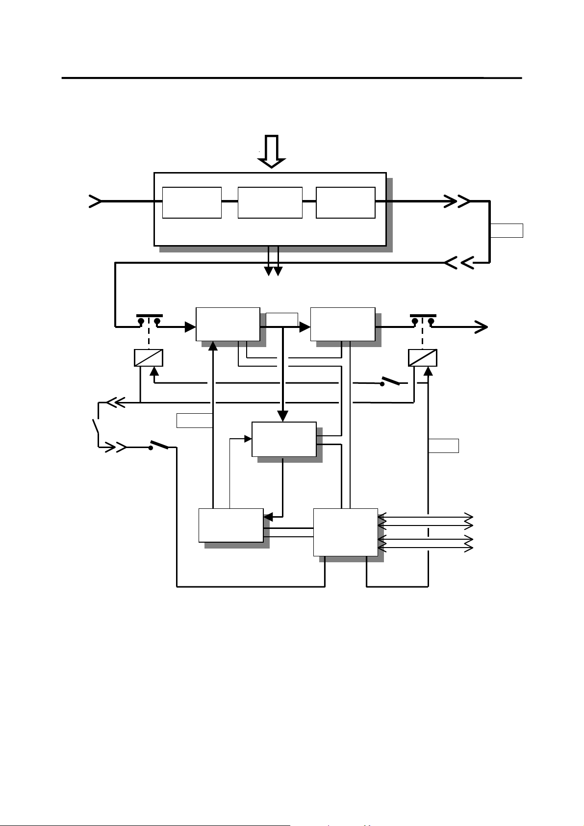
The M110BA-1 consists of two main sections: Power Conditioner and UPS (see Fig. 1).
The Power Conditioner is an isolation transformer (with RFI filters and spike absorbers). Both the
input and output of the Power Conditioner are available to the user via the external connectors of
the unit. This configuration allows the user to externally bypass the UPS section of the M110BA-1
without loosing the surge protection and noise filtering provided by the Power Conditioner. This
capability is extremely important in shipboard applications since most standard commercial
equipment is designed to operate safely from grounded AC lines, whereas in standard shipboard
electrical systems both lines are HOT and none may be grounded. The power conditioner allows
the safe connection of commercial equipment to standard shipboard electrical systems without
creating a safety hazard. See Section 3 for detailed connection diagram. In addition to 115Vac, the
isolation transformer provides a low voltage for the 24Vdc contactor supply. When AC input drops,
the 24Vdc is provided from battery power.
The UPS is composed of a high power factor AC-DC Converter, a Removable Battery Pack, a
Battery Charger, a DC-AC Inverter and a microcontroller-based Control Circuit.
The AC-DC Converter is a high frequency switching converter that provides 320VDC to the DC-AC
inverter. The AC-DC converter draws clean sine input current waveform and does not induce
electrical noise into the input lines.
The Removable Battery Pack contains the energy source used by the UPS to provide power during
AC input failures. The Battery Pack includes eight 12V / 5AH lead-acid, sealed, maintenance-free
type cells. It provides 10 minutes of full rated output power. The Battery Pack is not a serviceable
item. It cannot be disassembled, and can only be replaced as a single unit.
The Battery Charger is a high frequency, voltage-regulated and current-limited DC to DC converter.
It is powered from the 320VDC output of the AC-DC Input Converter and provides temperaturecompensated float charge to the Battery Pack.
The DC-AC Inverter is high frequency inverter that generates clean sine-shape 115VAC voltage
from the 320VDC output of the AC to DC Input Section. The DC-AC Inverter is current-limited and
has an overload protection circuit that turns it off (latched) after a delay from the time the load
exceeds 120%. The delay depends upon the overload level.
The Control Circuit is a microcontroller-based circuit that provides monitoring of the unit’s status
(battery charge, load level, input and output levels, etc.) and supports communications and front
panel status indicators.
Note that when the UPS is bypassed, an external circuit breaker (or fuse) must be used in order to
protect the Power Conditioner from overload. The circuit breaker may be on the input or output
side of the Power Conditioner. The Power Conditioner contains internal fuses on its input. These
internal fuses are intended only as a safety feature in case of an internal failure and should not be
used as overload protection devices.
1
Page 5
MILPOWER SOURCE 110BA1UM, REV(B)
R
R
115/220Vac
MANUAL
SELECT
J1
AC INPUT
115/230 VAC
REMOTE
ON/OFF
SWITCH
2 POLES INPUT
CONTACTO
J5
J5
MASTER
ON/OFF
SWITCH
RFI FILTER
& VARISTOR
ISOLATION
TRANSFORMER
Power Conditioner
Low Voltage To
Contactors
AC-DC
CONVERTER
120 VDC
320 Vdc
BATTERY
CHARGER
RFI FILTER
& VARISTOR
DC-AC
INVERTER
2 POLES OUTPUT
INPUT
ON/OFF
SWITCH
J1
EXTERNAL
BYPASS
J2
CONTACTO
24 VDC
115
J2
AC OUTPUT
115VAC
BATTERY
PACK
CONTROL
&
MONITOR
24VDC24VRTN
Figure 1: M110BA-1 Block Diagram
2
J4 RS-232
J3 DRY
CONTACTS
Page 6

MILPOWER SOURCE 110BA1UM, REV(B)
2. Setting the Input Voltage Range
Note: The input voltage range is set (prior to shipping) to 115VAC.
To change the input voltage range:
a) Turn off both Input and Master ON/OFF switches.
b) Disconnect connectors J1 and J2 from the rear panel.
c) Open the Input Voltage Setting access cover (2 screws).
d) Pull out the exposed connector handle upward.
e) Reconnect the connector in the desired location (the window should line up with the
desired voltage marking).
f) Close the access cover (tighten the two screws).
g) Verify that the desired AC input voltage matches the voltage seen through the window.
3. Installation Instructions
Before installing the unit, please read carefully the Safety Instructions at the beginning of this
manual.
Make sure that the input voltage setting is correct.
Make sure that the Master switch is in the OFF position.
Two circular connectors (J1 and J2) are provided on the rear panel of the UPS (see Figure 6). J1 is
the input connector to the Power Conditioner section of the unit. J2 carries the output of the
Power Conditioner and both input and output of the UPS section. (Please refer to Fig. 1 for the
definitions of the Power Conditioner and the UPS sections.)
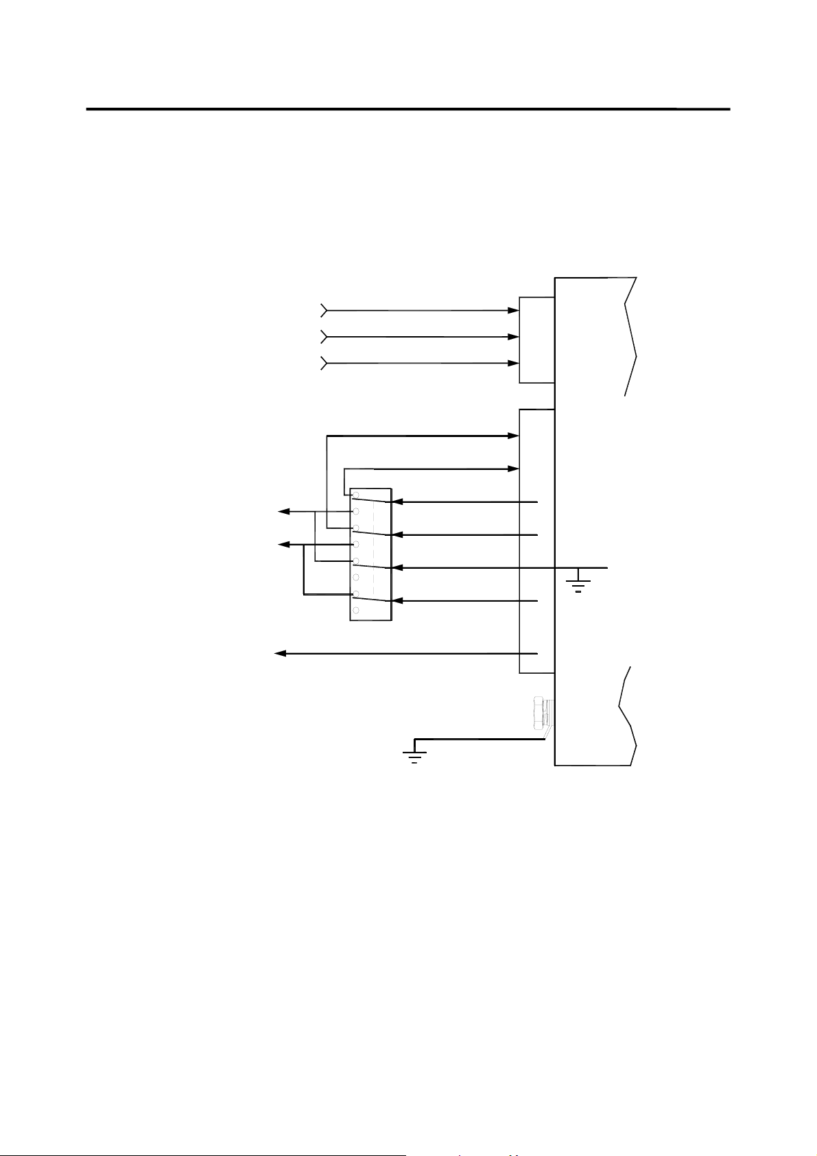
Use Figure 2 if it is desired to use the power conditioner as a buffer between the mains and the
load when the M110BA-1 is externally bypassed.
Please note that grounding of the power conditioner’s output is permitted only at the output side of
the bypass selector (marked as “NEUT” in figure 2).
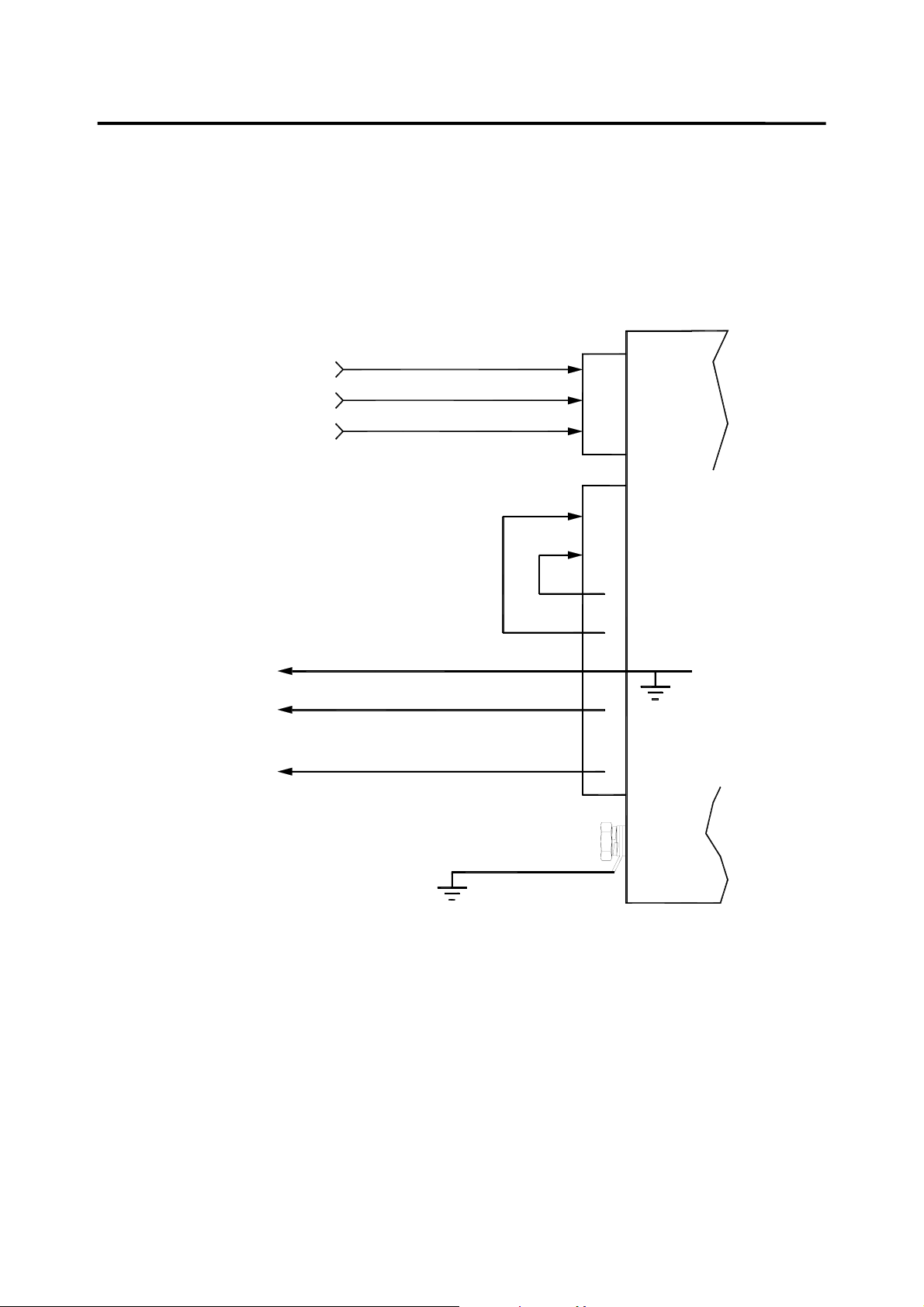
Use Figure 3 if bypass is not required,.
After the unit is installed and ready to be turned ON, see paragraph 6.1 (Turning the UPS ON and
OFF) for operating instructions.
3
Page 7
MILPOWER SOURCE 110BA1UM, REV(B)
115VAC
VIA TWO-POLE
20 AMP
CIRCUIT BREAKER
NEUT
AC TO
LOAD
BYPASS SELECTOR
HOT
(NO T E 2)
CHASSIS
GND
PWR COND . INPUT PHASE 2
PWR COND . INPUT PHASE 1
CHASSIS GND
UPS IN 2
UPS IN 1
PWR COND. OUT 1
PWR COND. OUT 2
UPS OUT 1 (NEUT)
UPS OUT 2 (HOT)
REAR PANEL
GND CONN.
SAFETY GND
C
B
J1
A
G
E
UPS
C
D
A
B
F
(NO T E 3 )
NOTES:
1. USE #8 WIRES.
2. POSITIONS OF BYPASS SELECTOR:
UPPER POSITIONS = UPS
LOWER POSITION = BYPASS
3. J2(A) IS INTERNALLY GROU N DE D
BY A REMOVAL JUMPER.
Figure 2 - Electrical Connections (with Bypass)
4
Page 8
MILPOWER SOURCE 110BA1UM, REV(B)
115VAC
VIA TWO-POLE
20 AMP
CIRCUIT BREAKER
AC TO
LOAD
CHASSIS
GND
PWR COND. INPUT PHASE 2
PWR COND. INPUT PHASE 1
CHASSIS GND
UPS OUT 1 (NEUT)
UPS OUT 2 (HOT)
C
B
J1
A
G
E
UPS
C
D
A
B
F
(NOTE 2 )
REAR PANEL
GND CONN.
SAFETY GND
NOTES:
1. USE #8 WIRES.
2. J2(A) IS INTERNALLY GROUNDED
BY A REMOVAL JUMPER.
Figure 3 - Electrical Connections (without Bypass)
5
Page 9
MILPOWER SOURCE 110BA1UM, REV(B)
4. Front Panel Description
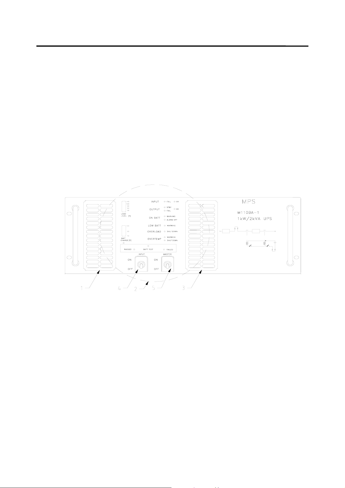
4.1 Front Panel: Main Components (See Figure 4)
1. Removable air filter (of the Power Conditioner’s cooling air).
2. Visual Indicators and Switches (for detailed view see Figure 5).
3. Air Inlet (of main UPS heatsink).
4. Input ON/OFF Switch.
5. Master ON/OFF Switch.
Figure 4 - Front Panel: Main Components
6
Page 10
MILPOWER SOURCE 110BA1UM, REV(B)
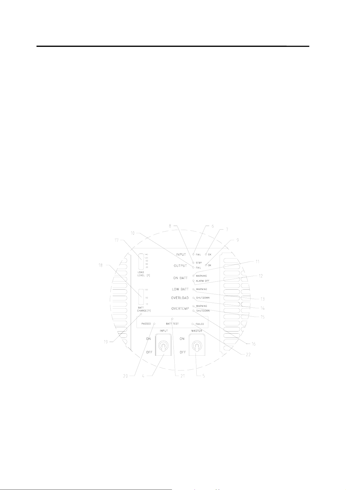
4.2 Front Panel: Indicators and Switches (See Figure 5)
4. Input ON/OFF switch.
5. Master ON/OFF switch.
6. Input Fail LED (red).
7. Input OK LED (green).
8. Output Standby LED (yellow).
9. Output OK LED (green).
10. Output Fail LED (red).
11. On Battery Warning LED (blinking yellow).
12. Alarm Off Push-button.
13. Low Battery Warning LED (blinking yellow).
14. Overload Shutdown LED (red).
15. Overtemperature Warning LED (blinking yellow).
16. Overtemperature Shutdown LED (red).
17. Load Level Bar Graph (marked in %, 100% = 1000W ).
18. Battery Charge Bar Graph (marked in %., 100% = 10 minutes at 1000W load).
19. Set Battery Charge to 100% Push-button (for maintenance only).
20. Battery Test Passed LED (green).
21. Battery Test Push-button.
22. Battery Test Failed LED (red).
Figure 5 - Front Panel: Indicators and Switches
7
Page 11
MILPOWER SOURCE 110BA1UM, REV(B)
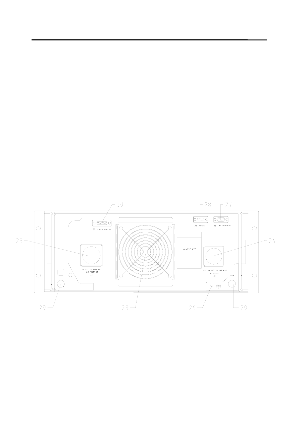
5. Rear Panel Description (See Figure 6)
23. Cooling Fan (Air Outlet).
24. J1 Input Power Connector (see Figure 2 for pin out).
25. J2 Output Power Connector (see Figure 2 for pin out).
26. GND Connection.
27. Dry Contacts Connector J3 (see paragraph 8 for pin out description).
28. RS232 Connector J4 (see paragraph 8 for pin out description).
29. Optional Bushing (2 places).
30. Remote ON/OFF connector J5.
Figure 6 - Rear Panel
8
Page 12

MILPOWER SOURCE 110BA1UM, REV(B)
6. Operation, Controls and Indicators (ref. Figures 4 and 5)
6.1 Turning the UPS ON and OFF
In order to turn the UPS ON (after an electrical connection is made), turn ON the Input ON/OFF
switch (4), the Master ON/OFF switch (5) and the remote ON/OFF switch. (The order is not
important). If remote ON/OFF is not used, the connections of J5 (described in para. 8.3) should be
installed before the unit is turned on.
When the Master ON/OFF switch (5) or the remote ON/OFF switch are turned off, the internal
contactors open and disconnect both the input and the output of the UPS and it turns OFF.
When the UPS operates, turning off the Input ON/OFF switch (4) disconnects the UPS from the AC
input, and the UPS then runs on battery power only.
To turn the UPS off, the Master ON/OFF switch or the remote ON/OFF switch must be in the OFF
position. (It will automatically disconnect the input connector too).
Note: The UPS will not start on battery power (to avoid battery discharge during shipping and
storage). Hence, the Input ON/OFF switch must be ON and AC voltage must be present at the input
in order to start the UPS.
When a remote control of the UPS is desired, the Input ON/OFF and the Master ON/OFF switches
on the front panel should be both in the ON position. Turning the remote ON/OFF switch ON and
OFF will turn the UPS ON and OFF. (Please see paragraph 8.3).
6.2 Visual Indicators
6.2.1 Normal Operation
When the UPS is running on AC input power and both Master and Input switches are ON, the two
bar graphs (17, 18), the green Input OK LED (7) and the green Output OK LED (9) are on.
The Load Level Bar Graph (17) indicates the loading percentage of the UPS. 100% load is equal to
1500W of output power. The lower six positions of the Load Level Bar Graph (15% to 75%) are
green. The next three positions (80%, 110%, 120%) are orange and the two uppermost positions
(130% and 140%) are red. The colors do not have any special significance and are only intended to
assist fast scanning of the load level.
The Battery Charge Bar Graph (18) indicates the percentage charge level of the battery. 100%
signifies that at least 10 minutes of full load will be supported by the battery, 50% signifies
5 minutes at full load and so on. Lower loads result in longer expected battery operation time.
When the battery is being charged, the uppermost active segment of the Battery Charge Bar Graph
blinks to indicate that charging is on.
6.2.2 Standby Mode
When the yellow Output Standby LED (8) is on, the UPS is in the Standby Mode. In this Mode the
DC-AC inverter is OFF and the output contactor is open, but all other function of the UPS are active
(including battery charging and RS-232 communication port). The UPS reaches this mode when
command by the RS-232 or the “dry relays” into this mode.
9
Page 13

MILPOWER SOURCE 110BA1UM, REV(B)
6.2.3 Input AC Failure
When the input AC voltage is below the minimum required for proper operation, the UPS runs on
battery power. During this condition the red Input Fail LED (6) is on, the yellow On Battery Warning
LED (11) blinks, and five seconds after input power loss an audible alarm starts beeping once
every five seconds.
To turn off the audible alarm, press momentarily on the Alarm OFF Push-button (12). When the
button is pressed, a short beep will sound to indicate compliance.
During battery operations, the Battery Charge Bar Graph (18) continuously displays the battery
charge level. When the charge in the battery drops below 35%, the yellow Low Battery Warning
LED (13) starts blinking (indicating that less than 3.5 minutes of full load may be supported by the
battery) and the audible alarm emits two short beeps once every five seconds..
To turn off the audible alarm, press momentarily on the Alarm OFF Push-button (12). When the
button is pressed, a short beep will sound to indicate compliance.
When the Battery Charge Bar Graph reaches 0% (no segments are lit), the UPS will continue to
operate until the actual voltage of the battery trips the battery protection circuit and shuts down the
UPS.
When the input AC voltage recovers, the UPS will turn on automatically.
6.2.4 Overload Condition
If the load exceeds the rating of the UPS or there is a short circuit on the UPS’s output, the
protection circuit of the UPS will shut down the UPS output (after a short delay, depending on the
depth of the overload).
This condition is indicated by the red Output Fail LED (10) and the red Overload Shutdown LED (14).
To recover from overload shutdown:
Turn off the Master ON/OFF switch (5).
Remove the overload (or short circuit) from the UPS output.
Turn on the Master ON/OFF switch (5).
The output may turn on immediately or after a short delay, depending on the duration the unit was
off. During this delay the yellow Output Standby LED (8) blinks.
6.2.5 Over Temperature Condition
When the internal temperature of the UPS exceeds a preset level, the yellow Over Temperature
Warning LED (15) blinks and audible alarm sounds at one second intervals, 50% duty cycle.
Three minutes after the Over Temperature Warning LED starts to blink (and if the temperature does
not drop), the UPS shuts itself off. This condition is indicated by the red Over Temperature
Shutdown LED (16) and the red Output Fail Led (10).
Recovery from Over Temperature Shutdown is automatic when the temperature drops.
Check condition of the Air Filter on the front panel. If it is dirty - clean it and re-install into the unit.
10
Page 14

MILPOWER SOURCE 110BA1UM, REV(B)
6.3 Battery Test
Battery Test may be invoked only if the UPS runs on AC input power, the Battery Charge level is
above 85%, the load is above 35% and the battery is not engaged in supporting Input Power Limit.
If Battery Test is denied due to low charge level, the Charge Level Bar Graph blinks once when the
Battery Test Push-button is pressed.
To test the battery, press momentarily on the Battery Test Push-button (21). The green Battery Test
Passed LED (20) will blink for about 3 seconds (indicating that Battery Test is running). After about
3 seconds, either the red Battery Test Failed LED (22) will turn on (and latch), indicating a bad
battery, or the green Battery Test Passed LED (20) will turn on for about 20 seconds, indicating that
battery successfully passed the test.
The Battery Test may be repeated only after at least 20 seconds have elapsed since the last test.
7. Taking Care of the Battery
7.1 Battery Service Life
The gel lead-acid, sealed and maintenance-free battery used in the M110BA-1 is of the highest
quality. Nevertheless, it is a Limited Life Item, and its life expectancy depends upon its operating
and storage conditions.
The three most important factors that determine the life of the battery are:
Temperature
Storage Conditions
Charge-Discharge Cycles
Temperature
The battery used in the M110BA-1 is sealed and does not “dry up” or lose gasses, but its end of
service life is brought about by the gradual corrosion of the electrodes. This process is
accelerated by high operating temperatures. Every 10°C rise above 20°C will reduce the battery
service life by half.
Storage Conditions
When lead-acid batteries are stored for extended periods of time, lead sulfate is formed on the
negative plates and insulates them.
The sulfating rate depends on the ambient temperature and the charge level of the battery. High
temperature and low charge level accelerate the sulfating and reduce the battery life.
In order to protect your battery from damage during storage:
• Make sure the battery is fully charged periodically (every 4 months if the temperature is
approximately 24°C, and every two months if the temperature is higher than 37°C) by operating
the UPS for at least four hours.
• Store the batteries in a cool place (may be stored separately from the UPS).
• Never store a discharged battery !!!
11
Page 15

MILPOWER SOURCE 110BA1UM, REV(B)
Charge-discharge Cycles
The number of times and the depth of battery discharges (during AC input failure) affects the
service life of the battery.
If the battery is allowed to discharge only to 50% of its charge, the number of charge-discharge
cycles (before it fails) will be three times the number of cycles had it been allowed to reach 30%
charge.
Battery life may be prolonged by limiting the operating time on battery power to the minimum
required by the system to perform an orderly shutdown.
7.2 Replacing the Battery Pack
For ease of use, the battery of the M110BA-1 is packaged within a Removable Battery Pack (MPS
P/N M357380) that may be ordered separately.
During storage, the Battery Pack may be removed and stored separately in a cooled ambient.
To remove the Battery Pack from the UPS:
a) Turn OFF the Master ON/OFF switches.
b) Disconnect J1 and J2 from the rear panel.
c) Open seven screws on the battery’s rear cover.
d) Open the Battery Connector access cov er. Remove screws.
e) Disconnect the connector by pulling upward.
f) Unscrew the right battery’s screws on the top and three screws on the right side
of the UPS (marked by a B” on the top and recessed on the side).
g) Hold the Battery Pack by the two edges on the sides (Caution: Two-man lift !!) and
lift it straight up.
To install a new battery:
a) Lower the Battery Pack straight into its place (at the right side of the UPS). Verify that
the battery mating connector and harness (near the front panel) are not
damaged by the battery.
b) Install the screws on the top and the right side without tightening them yet. After all
screws are in, torque them at 11 IN.LB for the #6 top screws and 22 IN.LB for the #8
side screws. Note: Suitable locking compound (Locktite 242, or similar) should be
applied to all screws.
c) Connect the battery connector.
d) Close the battery connector cover and tighten its screws (6.5 IN.LB).
e) Close the battery’s rear cover and tighten its screws (6.5 IN.LB).
f) Reconnect J1 and J2 to the rear panel.
The unit is now ready for operation.
Note: If the new battery is fully charged, press the Set-Battery-Charge-to-100%
Push-Button for ten seconds to set the charge level to full scale.
12
Page 16

MILPOWER SOURCE 110BA1UM, REV(B)
8. Communications and Remote Control
8.1 Dry Contacts Interface
Dry Contacts Interface is available through connector J3 ( a DB9 male connector located on the
rear panel). This interface allows control and monitoring of the UPS by a server. Two
configurations are available: Option 0 (Standard) and Option 1.
8.1.1 Option 0 (Standard) Dry Contacts Interface
Table 1 shows J3 pin assignment for Standard configuration, Option 0.
Table 1 Dry Contacts Connector J3 Pin Assignment, Standard configuration, Option 0
PIN I/O DESCRIPTION NOTES
1 O Fault Detect Signal Low (1)
2 O Fault Detect Signal High (1)
3 I Remote Shutdown (2)
4 O Not Battery Operation (3)
5 System Common Ground
6N.C.
7 O Battery Voltage Low (4)
8 O UPS On (5)
9 O Input Power Loss, Battery operation (3)
Notes to Table 1:
1. Pin 1 is shorted to pin 2 when any one of the following conditions occurs:
Over Temperature Condition
Battery failure
Charger Failure
Internal UPS Controller Failure
2. Connecting 5 to 12Vdc ( + to pin 3, - to pin 5) causes the UPS to shutdown if in Battery Mode
(latched). If in AC mode, the UPS enters a Standby Mode (Ac output is off, all other functions
are on.)
3. If the UPS operates on battery power, pin 9 is shorted to pin 5 and pin 4 is open. Otherwise, pin
4 is shorted to pin 5 and pin 9 is open.
4. If battery voltage is low, pin 7 is shorted to pin 5. Otherwise, pin 7 is open.
5. If UPS output is OK, pin 8 is shorted to pin 5. Otherwise, pin 8 is open.
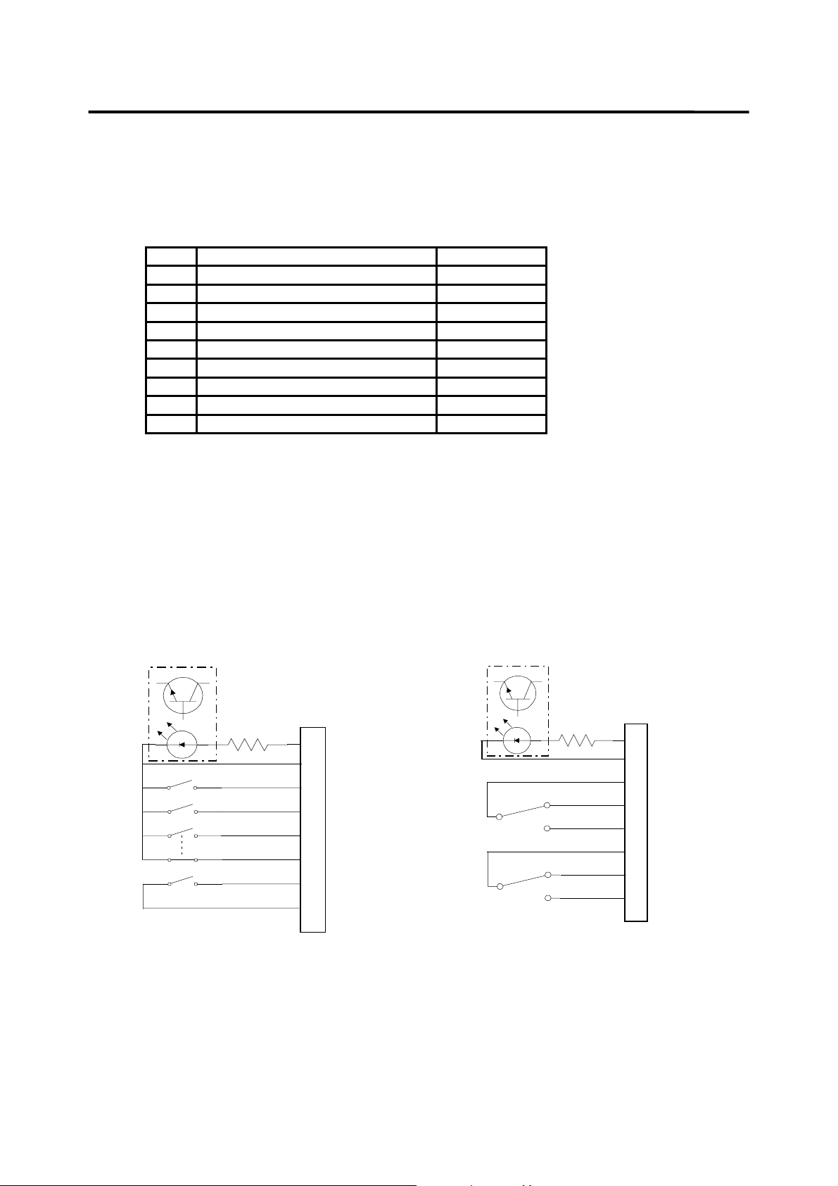
Figure 7 shows the dry contacts interface circuits for Option 0.
13
Page 17
MILPOWER SOURCE 110BA1UM, REV(B)
8.1.2 Option 1 Dry Contacts Interface
Table 2 shows J3 pin assignment for Option 1. In this option the server interfaces to the UPS via a
quasi - RS232 communication link
Table 2 Dry Contacts Connector J3 Pin Assignment, Option 1
PIN DESCRIPTION NOTES
1 Remote Shutdown Return (1)
2 Mains Fail Relay, normally closed (2)
3 Mains Fail Relay, normally open (2)
4 Low Bat Relay, normally open (3)
5 Low Bat Relay, normally closed (3)
6 Remote Shutdown (1)
7 Mains Fail Relay, center pole (2)
8 Low Bat Relay, center pole (3)
9N.C.
Notes to Table 2:
1. Connecting 5 to 12Vdc ( + to pin 6, - to pin 1) causes the UPS to shutdown if in Battery Mode
(latched).
2. If AC input is good, pin 7 is shorted to pin 2 and pin 3 is open.
If AC input is bad, pin 7 is shorted to pin 3 and pin 2 is open.
3. If battery voltage is good, Pin 8 is shorted to pin 5 and pin 4 is open.
If battery voltage is bad, Pin 8 is shorted to pin 4 and pin 5 is open
Fig 8 shows the dry contacts interface circuits for Option 1.
J3
1K
3 REMOTE S.D (+)
5 SYSTEM GND
7 BAT V LOW
8 UPS ON
9 BAT OPER
4 NOT BAT OPER
1 FLT DET HI
2 FLT DET LO
Figure 7 - Dry Contacts - Option 0
J3
1K
6 REMOTE S.D. (+)
1 RTN RMT S.D.
7 MAINS FAIL CTR
2 MAINS FAIL N.C.
3 MAINS FAIL N.O.
8 LOW BAT CTR
5 LOW BAT N.C.
4 LOW BAT N.O.
Figure 8 - Dry Contacts - Option 1
14
Page 18
MILPOWER SOURCE 110BA1UM, REV(B)
8.2 RS-232 Communication Interface
The RS232 serial communication interface is available through connector J4 ( a DB9 female
connector located on the rear panel of the UPS.) This interface allows control and monitoring of the
UPS by a host computer through the serial RS232 communication link. For further information
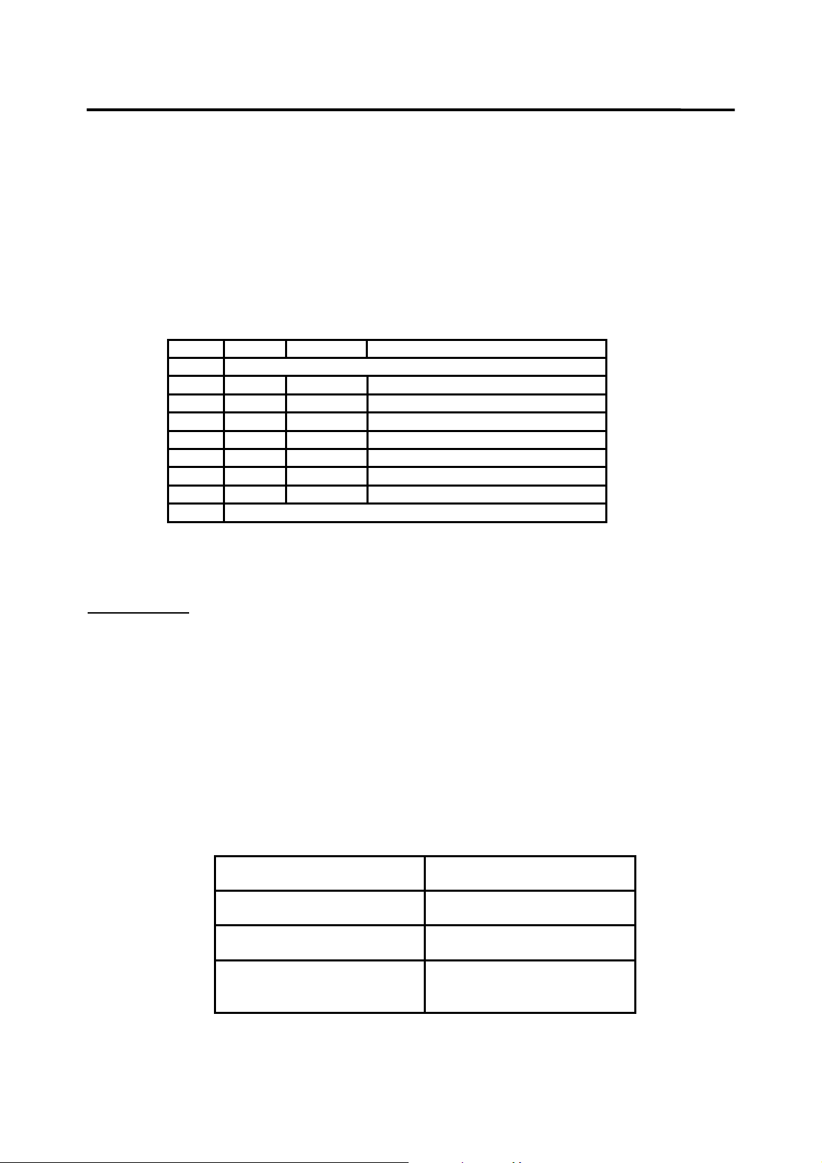
about this feature refer the M120BA-1 Software User Manual. Table 3 shows the standard RS232
pin assignment.
Table 3 - RS232 Connector J4 Pin Assignment
Pin I/O Symbol Description
1 Internally shorted to J3 pin 5. (not used by RS232 link)
2 Input RXD Receive Data
3 Output TXD Transmit Data
4 Output DTR Data Terminal Ready
5 --------- SG Signal Ground
6 Input DSR Data Set Ready
7 Output RTS Request To Send
8 Input CTS Clear To Send
9 Internally shorted to J3 pin 9. (not used by RS232 link)
8.3 Remote ON/OFF Interface J5
Important note: The M110BA-1 is shipped with a matting connector plugged into J5, with a jumper
that enables the unit. If remote ON/Off is not desired, do not remove it.
The
remote ON/OFF Interface J5 provides a mean for turning the UPS ON and OFF by a remote
panel switch. When pin 8 or 15 of J5 are connected to pin 7 or 14 of J5 (8 is internally connected to
15 and 7 is internally connected to 14) the UPS is enabled. It will be ON only if the Master ON/OFF is
also ON. When pins 8 and 15 are not connected (externally) to pins 7 or 14 the UPS will be OFF
regardless of the position of the switches on the front panel.
To control the UPS by the remote switch, leave the front panel switches in the ON position and turn
the UPS ON and OFF by closing (ON) and opening (OFF) the remote switch.
The remote switch should be rated to 28Vac, 0.5AMP.
Pin Symbol
8,15 Remote ON/OFF
7,14 Remote ON/OFF RTN
1 ÷ 6
9 ÷ 13
Not used
15
Page 19

MILPOWER SOURCE 110BA1UM, REV(B)
9. Specifications
INPUT
OUTPUT
Voltage
Frequency
Power Factor
Spikes
Isolation
Current
waveform
Line
impedance
Voltage
Rating
84-165VAC or 180-260VAC (selectable) without switching to battery power.
(below this level the battery will be used).
48-64 Hz
> 98%
200 joules clamping device
Input is galvanically isolated from output and chassis (> 1 MΩ at 600VDC).
Total capacitance between input and chassis is less than 0.02uf per line.
Leakage current is less than 2ma. (130dB Input Isolation Transformer.)
Both input wires may be “hot” I.A.W. MIL-STD-1399.
Sinusoidal, with very low harmonic content I.A.W. MIL-STD-1399 section
300A.
Up to 5 ohms between 100Hz and 200kHz (I.A.W. MIL-STD-1399 section
300A.)
115Vac ± 3% , grounded neutral (see Note 1)
2000VA, 1000W
BATTERY
EMC
Frequency
Waveform
Type
Capacity
Charger
Protection
Monitor
Federal
Military
60Hz ± 0.2% (digitally synthesized from a crystal oscillator)
Sinusoidal , THD < 2% (linear load), < 4% (non-linear)
Internal, encapsulated, sealed, maintenance-free, lead-acid.
Full rated power for at least 10 minutes.
Low ripple, regulated voltage float-charger, with current limiting and
temperature compensation. Fully charges the battery within 3 hours (following
10 minutes discharge at full power).
Battery is protected from over-discharge by internal protection circuit (to avoid
damage to battery in case of prolonged power outage.)
Battery charge level and internal impedance are monitored by the UPS microcontroller.
Meets the requirements of:
FCC Title 47 , part 15, class A.
MIL-STD-461D, RE101, RE102, CE101, CE102, CS101 and RS103.
ESD
All I/O lines are protected from ESD.
16
Page 20

MILPOWER SOURCE 110BA1UM, REV(B)
9. Specifications (continued)
ENVIRONMENT Temperature
Humidity
Altitude
Orientation
Mechanical
shock
Vibration
INDICATIONS
& CONTROLS
a) Visual
Indications
(Front panel)
Non operating: -40 to +72°C
Note: High temperature for prolonged duration will shorten the battery life.
Operating: 0 to +52°C.
Up to 95%.
Operating: Up to 10,000 feet.
Non-operating: (Air transport) 40,000 feet.
May be installed at any orientation.
When packed, withstands the free fall drop and edgewise drop IAW
Methods 5007.1 and 5008.1 of Federal Test Method standard 101C.
When operating, withstands the high-impact shipboard shock IAW
MIL-S-901D, grade A, class II., Type B.
When operating, withstands Type I vibration IAW MIL-STD-167-1. The
UPS will endure a sweep of 1.5g sinusoidal vibration from 5 to 50 Hz for a
total duration of 2 hours, and random vibration IAW MIL-STD-810D, Cat.
9, Proc. I (test condition I-3.2.11, Fig. 514.3-34)
10-segment tri-color Bar Graph for load level display.
10-segment Bar Graph for battery charge level display.
"Output OK", "Output Fail" and “Standby” status lamps.
"Input OK" and "Input Fail" status lamps.
"On Batt " status lamp.
"Batt Passed" and "Batt Failed" lamps for battery self-test.
"Low Batt" warning lamp.
"Overload Shutdown" status lamp.
"Overtemp warning" and "Overtemp Shutdown" lamps.
b) Test Mode
c) Audible
Alarm
d) Power
Switches
e) Remote
ON/OFF
When test mode is invoked by pressing the push-button on the front panel,
the UPS performs battery impedance testing without interrupting the output
power (even if the battery fails) utilizing a proprietary time-sharing circuit.
The test results are displayed on panel indicators.
End-to-End testing of the UPS is accomplished by cycling the INPUT
ON/OFF switch on the front panel.
The UPS will beep when it operates on battery power or during overtemperature condition. The alarm may be silenced by pressing the "Alarm
Off" push-button on the front panel.
The M110BA-1 has two double-pole contactors, one on the input and one on
the output.
The input ON/OFF contactor is controlled by the input ON/OFF switch
located on the front panel.
The Master ON/OFF switch, located on the front panel, shuts down the UPS
and opens both input and output contactors when in the OFF position.
When the two ON/OFF pins are opened the UPS will turn OFF and the
input and output contactors will open. When the two lines are shorted
together the front panel switches determine the status. (The UPS is supplied
with a mating connector and a jumper between the two ON/OFF pins).
17
Page 21

MILPOWER SOURCE 110BA1UM, REV(B)
INTERFACE Discrete
interface
Serial
Interface
Four dry contacts indicating the following conditions:
"UPS ON" (Output OK)
"Battery Voltage Low"
"Input Power Loss" (Battery Operation)
"Fault Detect"
A "Shutdown" input (via opto-isolator) for remote shutdown of the UPS during
AC input fail. When the AC input recovers the UPS will automatically turn ON.
Two pinout configurations are available:
Standard (Option -0) and Alternate (Option -1, see “SOFTWARE” below)
RS-232 Serial port (EIA-RS-232).
The serial port allows transmission of status and reception of User-Programmable
Options, some of which are described below:
Status: Input OK, Output OK, On Battery, Low Battery, Over-Temperature
Warning, Battery Test Passed/Failed, Load Level, Charge Level, status of all User
Programmable Options and failure diagnostic.
Commands: UPS Shutdown, UPS Standby, Initiate Battery Test, Enable/Disable
Periodic Battery Test, Enable/Disable Battle Mode, Enable/Disable Aural Alarm,
Set Input power Limit (see Note 2), Protection Reset (resets all latching protection
circuits), System Reset ( forces all User Programmable Options into their default
state and resets all latching protection circuits).
For the complete set of the available Status messages and Commands, refer to the
User’s Manual.
SCREENING
ACOUSTIC
NOISE
Notes
1. The Neutral Grounding Link is accessible to the user and may be removed to obtain a floating output.
2. This option allows the user to feed the UPS from a limited power outlet. When in this mode, momentary peak
power will be supported by the internal battery.
Environmental stress screening (including: thermal cycles, vibration and power
burn-in) is available upon request.
Less than 48dBA.
18
 Loading...