

Milnor MCR09E5, MWR18X4, MCR18E4, MWR09E5, MWR18E4 Service Manual

Published Manual Number/ECN: MPIMCRXXAE/2006486A
• Publishing System: TPAS
• Access date: 12/5/2006
• Document ECN's: Exact
Installation and Service—
MCR09E5,MCR18E4
MWR09E5,MWR18E4
MWR18X4
Washer Extractor
PELLERIN MILNOR CORPORATION POST OFFICE BOX 400, KENNER, LOUISIANA 70063-0400, U.S.A.

Please Read
About the Manual Identifying Information on the Cover
The front cover displays pertinent identifying information for this manual. Most important, are
the published manual number (part number) /ECN (date code). Generally, when a replacement
manual is furnished, it will have the same published manual number, but the latest available ECN.
This provides the user with the latest information applicable to his machine. Similarly all
documents comprising the manual will be the latest available as of the date the manual was
printed, even though older ECN dates for those documents may be listed in the table of
contents.
When communicating with the Milnor factory regarding this manual, please also provide the
other identifying information shown on the cover, including the publishing system, access date,
and whether the document ECN’s are the latest available or exact.
References to Yellow Troubleshooting Pages
This manual may contain references to “yellow pages.” Although the pages containing
troubleshooting procedures are no longer printed on yellow paper, troubleshooting instructions, if
any, will be contained in the easily located “Troubleshooting” chapter or section. See the table of
contents.
Trademarks of Pellerin Milnor Corporation
The following, some of which may be used in this manual, are trademarks of Pellerin Milnor
Corporation:
Comments and Suggestions
Help us to improve this manual by sending your comments to:
®
CBW
E-P Express
E-P OneTouch
E-P Plus® Mildata® MultiTrac™
®
Gear Guardian® Milnet® Staph Guard®
®
Mentor® Milnor® Visionex™
Pellerin Milnor Corporation
Attn: Technical Publications
P. O. Box 400
Kenner, LA 70063-0400
Fax: (504) 469-1849

Table of Contents
for MPIMCRXXAE/2006486A
MCR09E5,MCR18E4 MWR09E5,MWR18E4 MWR18X4 Washer Extractor
Page Description Document/ECN
1 Warranty BMP720097/92732A
3 How to Order Parts BMP720097R/72332A
4 Safety Placard Use and Placement MCR09E5, MCR18E4 BMP050019/2006052B
6 Safety PLacard Use and Placement MWR09E5,
MWR18E4, MWR18X4 BMP050050/2006416B
8 Guards and Covers BMP050007/2006416B
10 About the Forces Transmitted by Milnor Washer-Extractors BIWUUI02/20001108
12 Glossary of Tag Illustrations-30" G, T and V style WE MSIUUMTGAE/2004072V
17 Avoiding Damage from Allied Remote Chemical
Delivery Systems BIWUUI03/20030306
22 Handling and Setting Procedures for Rigid Mount
Washer-Extractors BIRUUI01/20050221
25 External Fuse/Breaker, Wiring, and Disconnect
Requirements BFUUUF01/20051027
26 MCR09E5, MWR09E5 BFRCAF01/20060725
27 MCR18E4 and MWR18E4 BFRCBF01/20060131
28 Service Connections BIRQVI01/20060420
31 Section 1: Service and Maintenance
32 Preventive Maintenance BIRQUM01/20050302
35 Section 2: Drive Assemblies
36 Drive Chart BMP050008/2006416B
37 Motor Mount BMP050004/2006416B
39 Section 3: Bearing Assemblies
40 Bearing Assembly & Installation BMP060001/2006446B
43 Section 4: Shell and Door Assemblies
44 Door Installation BMP040094/2006482B
47 Door Lock Mechanism BMP060002/2006416B
49 Door Locking Handle BMP060003/2006416B
51 Section 5: Control and Sensing
52 Coin Acceptor & Vault BMP040093/2006033B
54 Level Switch BMP050006/2006416B
55 Vibration Safety Switch Adjustments MSSMA408BE/9273BV
57 Vibration Safety Switch BMP050009/2006416B
59 Section 6: Chemical Supply
60 Soap Chute MCR09E5, MCR18E4 BMP060004/2006482B
63 Soap Chute MWR09E5, MWR18E4 BMP060005/2006482B
66 Soap Chute MWR18X4 BMP060056/2006482B
69 Section 7: Water and Drain

Table of Contents, cont.
Page Description Document/ECN
70 Water Inlet Installation MCR09E5, MCR18E4 BMP050003/2006416B
72 Water Inlet Installation MWR09E5, MWR18E4, MWR18X4 BMP060006/2006416B
75 3/4" Duo Inlet with 1/2" Hose Outlet BMP050001/2005032V
76 3/4" Inlet with 3 Hose Outlet BMP050002/2006172B
77 Drain Installation BMP050005/2006077B
79 Section 8: Dimensional Drawings
81 Dimensional Drawing - MCR09E5, MWR09E5 BDMCR09EAE/2006416D
82 Dimensional Drawing - MCR18E4, MWR18E4, MWR18X4 BDMCR18EAE/2006416D
83 Dimensional Drawing - Pedestal Base for (1)
MCR09E5, MWR09E5 BDMCRBB1AE/2006154D
84 Dimensional Drawing - Pedestal Drawing for
(2) MCR09E5, MWR09E5 BDMCRBB2AE/2006033D
85 Dimensional Drawing - Pedestal for (4) MCR09E5,
MWR09E5 BDMCRBB4AE/2006033D
86 Dimensional Drawing - Pedestal for (1) MCR18, MWR18 BDMCRBL1AE/2006422D
87 Dimensional Drawing - Pedestal Base for (2)
MCR18, MWR18 BDMCRBL2AE/2006422D
88 Dimensional Drawing - Pedestal for (4) MCR18, MWR18 BDMCRBL4AE/2006422D

3(//(5,10,/125&25325$7,21
/,0,7('67$1'$5':$55$17<
We warrant to the original purchaser that MILNOR machines including electronic
hardware/software (hereafter referred to as “equipment”), will be free from defects in material
and workmanship for a period of one year from the date of shipment from our factory with no
operating hour limitation. This warranty is contingent upon the equipment being installed,
operated and serviced as specified in the operating manual supplied with the equipment, and
operated under normal conditions by competent operators.
Providing we receive written notification of a warranted defect within 30 days of its discovery,
we will – at our option – repair or replace the defective part or parts, FOB our factory. We
retain the right to require inspection of the parts claimed defective in our factory prior to
repairing or replacing same. We will not be responsible, or in any way liable, for unauthorized
repairs or service to our equipment, and this warranty shall be void if the equipment is repaired
or altered in any way without MILNOR’s written consent.
Parts which require routine replacement due to normal wear – such as gaskets, contact points,
brake and clutch linings and similar parts – are not covered by this warranty, nor are parts
damaged by exposure to weather or to chemicals.
We reserve the right to make changes in the design and/or construction of our equipment
(including purchased components) without obligation to change any equipment previously
supplied.
ANY SALE OR FURNISHING OF ANY EQUIPMENT BY MILNOR IS MADE ONLY UPON
THE EXPRESS UNDERSTANDING THAT MILNOR MAKES NO EXPRESSED OR IMPLIED
WARRANTIES OF MERCHANTABILITY OR FITNESS FOR ANY PARTICULAR USE OR
PURPOSE. MILNOR WILL NOT BE RESPONSIBLE FOR ANY COSTS OR DAMAGES
ACTUALLY INCURRED OR REQUIRED AS A RESULT OF: THE FAILURE OF ANY OTHER
PERSON OR ENTITY TO PERFORM ITS RESPONSIBILITIES, FIRE OR OTHER HAZARD,
ACCIDENT, IMPROPER STORAGE, MISUSE, NEGLECT, POWER OR ENVIRONMENTAL
CONTROL MALFUNCTIONS, DAMAGE FROM LIQUIDS, OR ANY OTHER CAUSE BEYOND
THE NORMAL RANGE OF USE. REGARDLESS OF HOW CAUSED, IN NO EVENT SHALL
MILNOR BE LIABLE FOR SPECIAL, INDIRECT, PUNITIVE, LIQUIDATED, OR
CONSEQUENTIAL COSTS OR DAMAGES, OR ANY COSTS OR DAMAGES WHATSOEVER
WHICH EXCEED THE PRICE PAID TO MILNOR FOR THE EQUIPMENT IT SELLS OR
FURNISHES.
WE NEITHER ASSUME, NOR AUTHORIZE ANY EMPLOYEE OR OTHER PERSON TO
ASSUME FOR US, ANY OTHER RESPONSIBILITY AND/OR LIABILITY IN CONNECTION
WITH THE SALE OR FURNISHING OF OUR EQUIPMENT TO ANY BUYER.
BMP720097
92732A


How to order repair parts
Repair parts may be ordered either from the authorized dealer who sold you this
machine, or directly from the MILNOR factory. In most cases, your dealer will
have these parts in stock.
When ordering parts, please be sure to give us the following in formation:
1. Model and serial number of the machine for which the parts are required
2. Part number
3. Name of the part
4. Quantity needed
5. Method of shipment des ired
6. In correspondence regarding motors or electrical controls, please include all
nameplate data, including wiring diagram number and the make or
manufacturer of the motor or controls.
All parts will be shipped C.O.D. transportation charges collect on ly.
Please read this manual
It is strongly recommended that you read the installation and operating manual
before attempting to install or operate your machine. We suggest that this manual
be kept in your business office so that it will not become lo st.
PELLERIN MILNOR CORPORATION
32%2;.(11(5/$ 86$
FAX: Administration 504/468-9307, Engineering 504/469-1849, Service 504/469-9777
BMP720097R
72332A
R
Pellerin Milnor CorporationPellerin Milnor Corporation
P. O. Box 400, Kenner, LA 70063-0400
Litho in U.S.A.
BMP050019/2006052B
(Sheet 1 of 2)
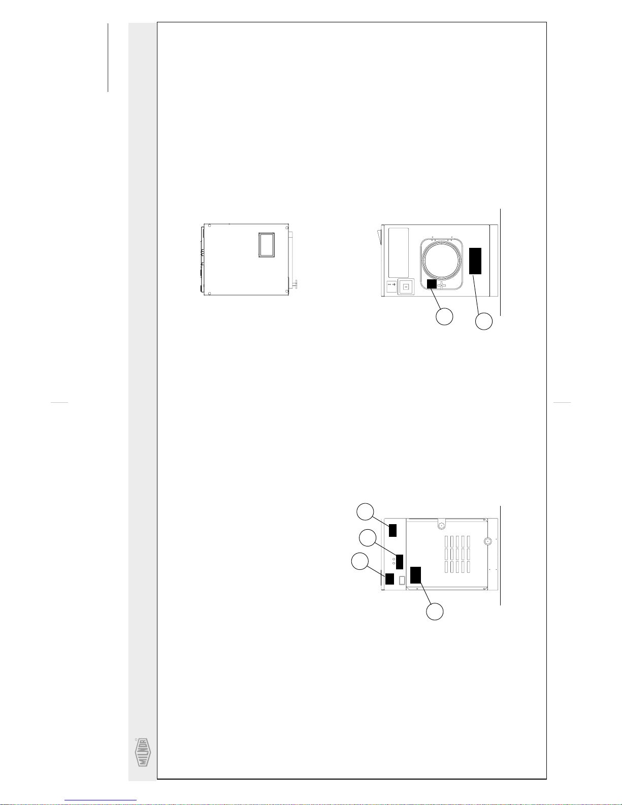
Safety Placard Use and Placement
MCR09E5, MCR18E4
Notes:
1
. Approximate locations of placards are shown.
Mounting holes are provided on machine.
If aluminum placard use #8 self-tapping screws.
. Replace placard immediately, if removed or
unreadable.
2
30
40
60
20
50
10
PLAN VIEW
FRONT VIEW
REAR VIEW
C H

R
Pellerin Milnor CorporationPellerin Milnor Corporation
P. O. Box 400, Kenner, LA 70063-0400
Litho in U.S.A.
BMP050050/2006416B
(Sheet 1 of 2)
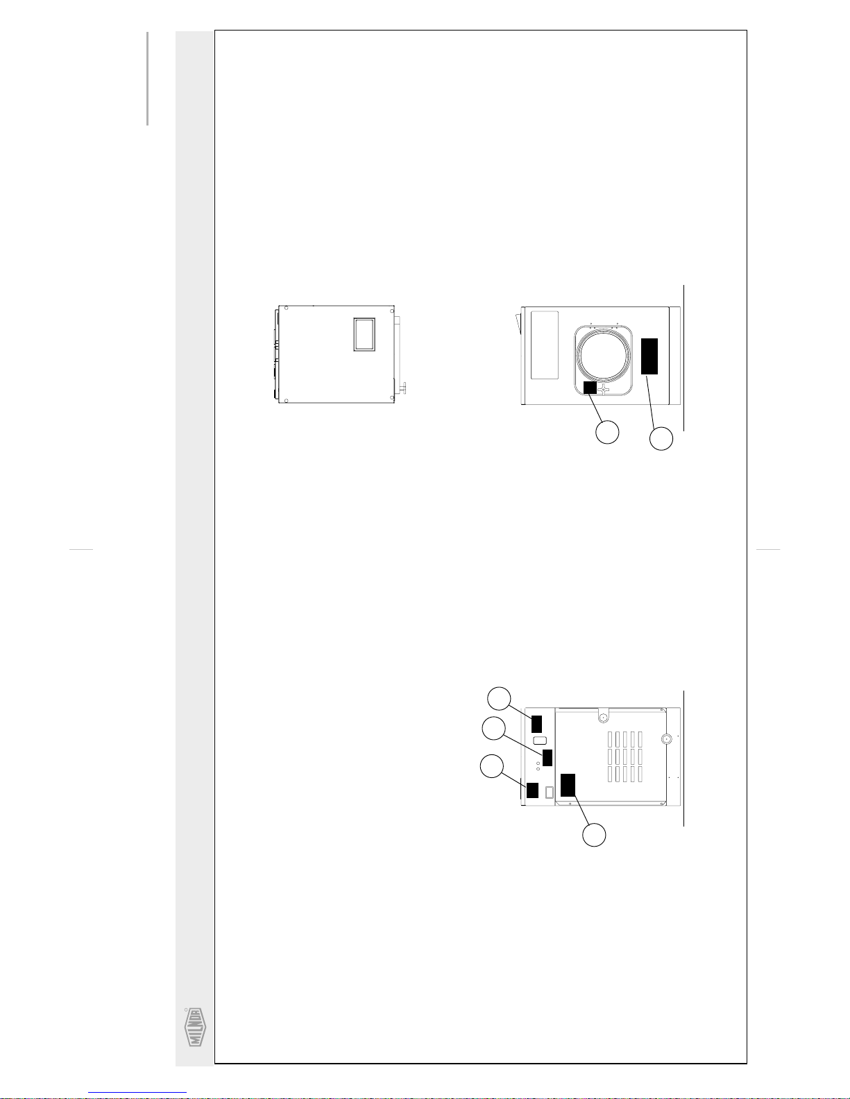
Safety Placard Use and Placement
MWR09E5, MWR18E4, MWR18X4
Notes:
1
. Approximate locations of placards are shown.
Mounting holes are provided on machine.
If aluminum placard use #8 self-tapping screws.
. Replace placard immediately, if removed or
unreadable.
2
30
40
60
20
50
10
PLAN VIEW
FRONT VIEW
REAR VIEW
C H

R
Pellerin Milnor CorporationPellerin Milnor Corporation
P. O. Box 400, Kenner, LA 70063-0400
Litho in U.S.A.
BMP050007/2006416B
(Sheet 1 of 2)
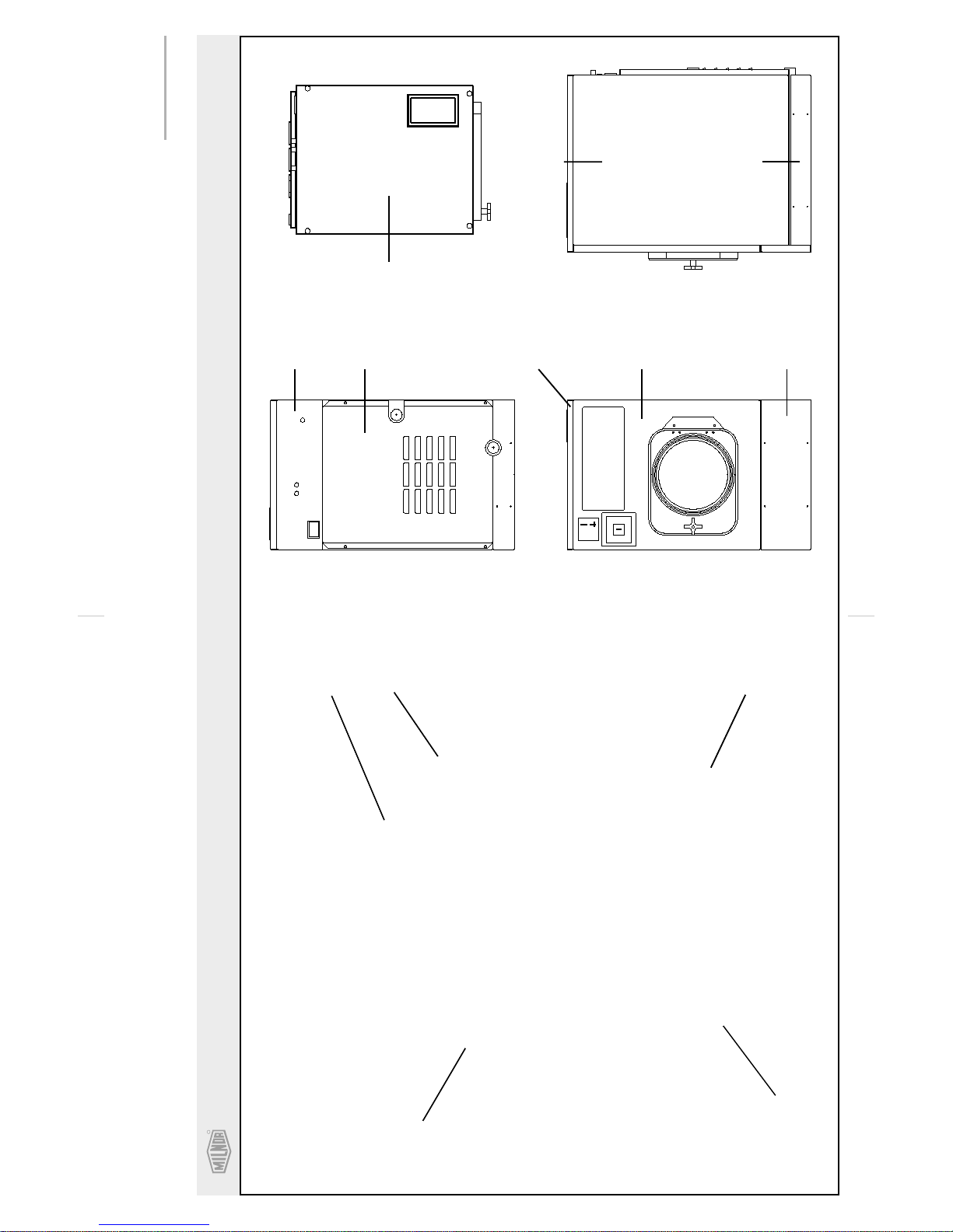
Guards and Covers
MCR09E5, MCR18E4, MWR09E5, MWR18E4, MWR18X4
REAR
TOP
FRONT
RIGHT
5
4
3
3
(LEFT &
RIGHT SIDES)
7
6
1
(LEFT &
RIGHT SIDES)
2
7
1
6
2
CH
MWR18X4
EP EXPRESS
CONTROLS
NOT SHOWN


About the Forces Transmitted by Milnor® Washer-extractors
2
8
8
8
U
About the Forces Transmitted by Milnor
Washer-extractors
During washing and extracting, all washer-extractors transmit both static and dynamic
(cyclic) forces to the floor, foundation, or any other supporting structure. During washing, the
impact of the goods as they drop imparts forces which are quite difficult to quantify. Size for size,
both rigid and flexibly-mounted machines transmit approximately the same forces during
washing. During extracting, rigid machines transmit forces up to 30 times greater than equivalent
flexibly-mounted models. The actual magnitude of these forces vary according to several factors:
• machine size,
• final extraction speed,
• amount, condition, and type of goods being processed,
• the liquor level and chemical conditions in the bath preceding extraction, and
• other miscellaneous factors.
Estimates of the maximum force normally encountered are available for each Milnor
and size upon request. Floor or foundation sizes shown on any Milnor
on-grade situations based only on previous experience without implying any warranty, obligation,
or responsibility on our part.
1.
Rigid Machines
Size for size, rigid washer-extractors naturally require a stronger, more rigid floor,
foundation, or other supporting structure than flexibly-mounted models. If the supporting soil
under the slab is itself strong and rigid enough and has not subsided to leave the floor slab
suspended without support, on grade installations can often be made directly to an existing floor
slab if it has enough strength and rigidity to safely withstand our published forces without
transmitting undue vibration. If the subsoil has subsided, or if the floor slab itself has insufficient
strength and rigidity, a deeper foundation, poured as to become monolithic with the floor slab,
may be required. Support pilings may even be required if the subsoil itself is “springy” (i.e., if its
resonant frequency is near the operating speed of the machine). Above-grade installations of rigid
machines also require a sufficiently strong and rigid floor or other supporting structure as
described below.
®
Document..................... BIWUUI0
Specified Date.................2000110
As-of Date.......................2000110
Access Date..................... 2000110
Applicability...........................WU
®
®
document are only for
model
2.
Flexibly-mounted Machines
Size for size, flexibly-mounted machines generally do not require as strong a floor,
foundation, or other supporting structure as do rigid machines. However, a floor or other
supporting structure having sufficient strength and rigidity, as described in section 3, is
nonetheless vitally important for these models as well.
3.
How Strong and Rigid?
Many building codes in the U.S.A. specify that laundry floors must have a minimum live
load capacity of 150 pounds per square foot (732 kilograms per square meter). However, even
compliance with this or any other standard does not necessarily guarantee sufficient rigidity. In
any event, it is the sole responsibility of the owner/user to assure that the floor and/or any other
supporting structure exceeds not only all applicable building codes, but also that the floor and/or
any other supporting structure for each washer-extractor or group of washer-extractors actually
has sufficient strength and rigidity, plus a reasonable factor of safety for both, to support the
weight of all the fully loaded machine(s) including the weight of the water and goods, and
including the published 360º rotating sinusoidal RMS forces that are transmitted by the
machine(s). Moreover, the floor, foundation, or other supporting structure must have sufficient
rigidity (i.e., a natural or resonant frequency many times greater than the machine speed with a
reasonable factor of safety); oth erwi se, the menti oned 360º ro ta ting sinu so ida l RMS forces can be
multiplied and magnified many times. It is especially important to consider all potential vibration
problems that might occur due to all possible combinations of forcing frequencies (rotating
speeds) of the machine(s) compared to the natural frequencies of the floor and/or any other
supporting structure(s). A qualified soil and/or structural engineer must be engaged for this
purpose.
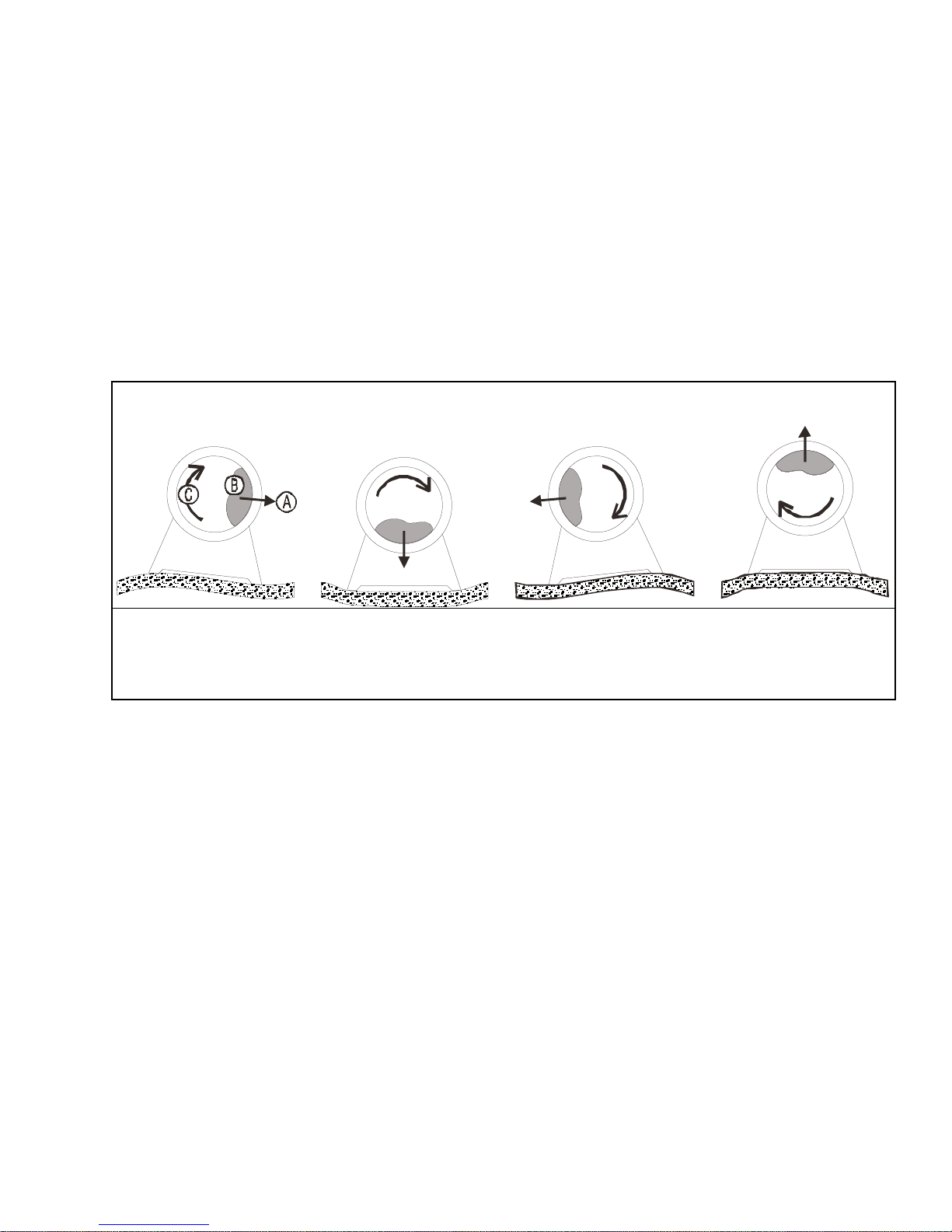
Figure 1: How Rotating Forces Act on the Foundation
Typical Machine
A.
Direction of force
B.
Load
C.
Rotation (Frequency = RPM / 60)
Figure 1 above is intended to depict both on-grade and above-grade installations and is
equally applicable to flexibly-mounted washer-extractors, as well as to rigid models installed
either directly on a floor slab or on a foundation poured integrally with the slab. Current machine
data is available from Milnor
have changed since last printed. It is the sole responsibility of every potential owner to obtain
written confirmation that any data furnished by Milnor
number(s) of the specific machines.
Legend
®
upon request. All data is subject to change without notice and may
®
applies for the model(s) and serial
— End of BIWUUI02 —
<B8DD<C604!#&!E
7
\_ccQbi_VDQW9\\ecdbQdY_^c±
7Cdi\U# DCdi\U# FCdi\U
GQcXUb5hdbQSd_bc
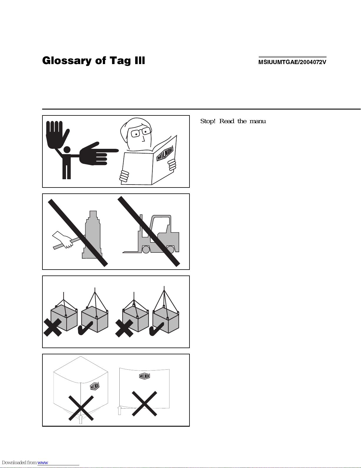
Illustration Explanation Illustration Explanation
Stop! Read the manual first for complete
instructions before continuing.
Do not jack the machine here.
Do not lift the machine here.
Use three point or four point lifting as
determined by the lifting eyes furnished. Rig
the load using lifting cables of sufficient size
and length to ensure cables are not
over-stressed.
Do not lift the machine from one corner or one
side edge.
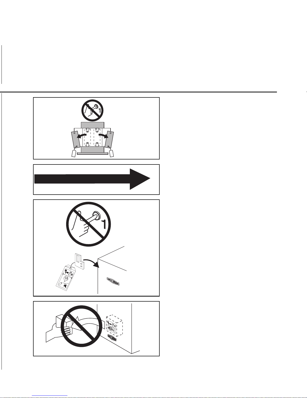
Do not start this machine until the packing
materials, lifting brackets, etc. with this tag
attached or behind this panel are removed.
These materials are painted red. Safety stands
or brackets (also painted red) may be provided
with this machine. Do not discard safety
stands or brackets
This motor or pump should rotate in the
direction of the arrow.
Do not start this machine until the part with
this tag is installed on the machine.
Do not remove this component from the
machine.
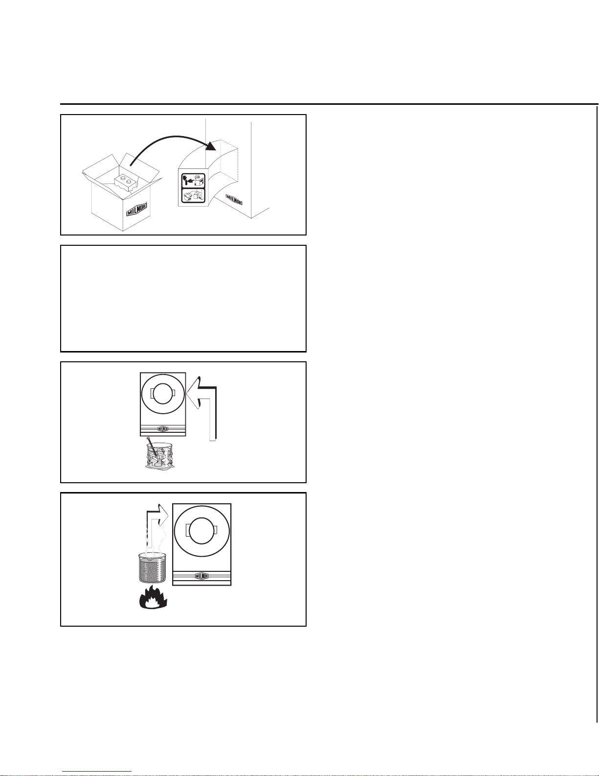
Illustration Explanation Illustration Explanation
Install the appropriate part here before
operating the machine.
During drain and extract, the cylinder must
rotate counterclockwise when viewed from
here (rear of machine).
Make cold water connection here.
Make hot water connection here.
H0
2
H0
2
H0
2
H0
2
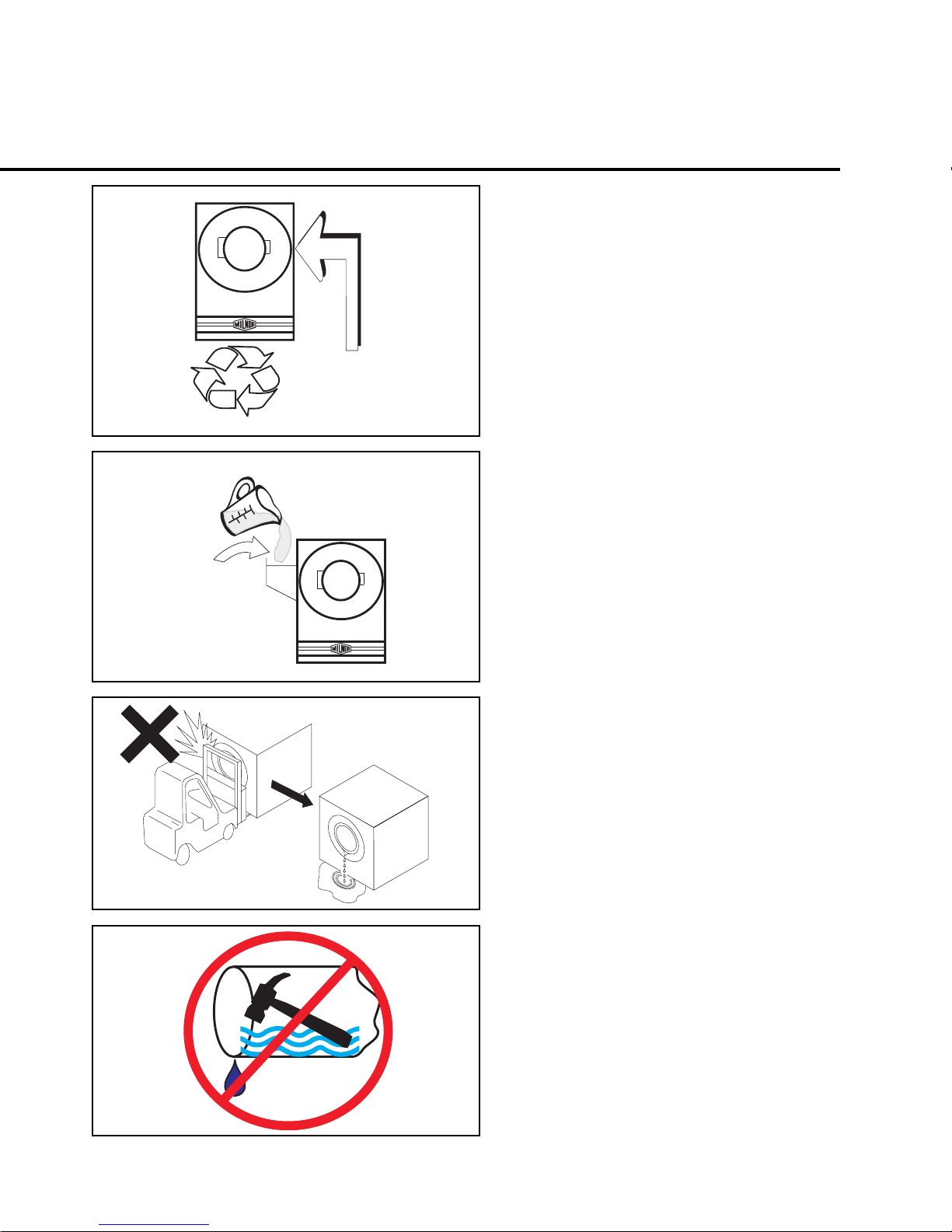
Make third (reuse) water connection here.
Make flushing water connection here.
Do not strike shell front of washer-extractors
during fork lifting. Striking shell front will
cause door to leak.
Water hammer will rupture the water inlet
valves on this machine. Eliminate water
hammer on waterlines to this machine. Follow
all applicable codes when installing water
hammer arresters on water lines.
H0
2
H0
2
Excessive water temperture will damage
valves. Do not e xceed 160 degrees Fahrenheit
(71 degrees Celsius).
Excessive air pressure will damage valves.
Do not exceed 80 psi (5.5 bar).
°
°
160 F
71 C
F
o
C
o
10-75psi
0.7 - 5.1 bar

BIWUUI03 (Published) Book specs- Dates: 20030306 / 20030306 / 20030306 Lang: ENG01 Applic: WUU
Avoiding Damage From Allied Remote Chemical Delivery
Systems
Milnor® does not manufacture or supply remote chemical delivery systems and this document is
meant only to illustrate some of the possible problems that can be minimized during installation
of such systems by the chemical supply company. Milnor washer-extractors and CBW
washers (tunnels) are available with convenient inlets for such systems (see Figure 1). Most
common of the types of systems currently used in commercial laundering operations are pumped
chemical systems. Other types, such as constant pressure, re-circulating ring main systems have
also been, and may continue to be used with Milnor equipment.
This document warns about some of the possible hazards posed by chemical systems and lists
certain requirements needed to minimize those hazards. The procedures for interfacing with allied
chemical systems and information pertinent to chemical use in general are provided elsewhere in
the product manuals (see Note 1).
Figure 1: Pumped Chemical Inlets on CBW Batch Washer
®
batch
Note 1:
permitting acid sours to react with hypo chlorite) due to incorrect formulation can also be hazardous.
Information pertinent to chemical us e i s provided elsewhere in the product manuals.
1.
How a Chemical System Can Damage the Machine It Serves
Misuse of laundering chemicals (such as injecting excessive con centrations of chlorine bl each or
Milnor has manufactured washer-extractors and tunnel washers with the same stainless steel
specification since its founding. Every batch of steel used is certified and documented by the steel
mill. Testing of samples damaged by corrosion have, in every case, proven the steel to be well
within the AISI 304 specification.
PELLERIN MILNOR CORPORATION

Avoiding Damage From Allied Remote Chemical Delivery Systems
Chemical products commonly found in the laundry industry, when used in established dosages
and proper operating parameters, under the auspices of an experienced chemical specialist, should
produce satisfactory results, with no consequential detrimental effects. The industry has published
standards in Riggs and Sherrill, “Textile Laundering Technology”. However, the stainless steel
can be damaged and even destroyed by abnormal contact with chlorine bleach, hydrofluosilicic
acid and other commonly used chemicals, as will occur if chemicals are unintentionally leaked
into the machine, particularly when it is no longer in use and especially when machine surfaces
are dry.
Some chemical systems have been found to permit chemicals to dribble from the supply lines, or
worse, to siphon from the supply tank into the machine, during operation and long after the
system is shut down—as after working hours and during weekends. If this occurs, deterioration
(rusting) of the stainless steel and damage to any textiles therein will inevitably result. If this
condition goes undetected, machine damage is likely to be catastrophic. No machine is
immune to such damage.
CAUTION 1 : Equipment and Textile Damage Hazards
—Chemicals leaked into the
machine, particularly when it is idle can destroy machine components and textiles left in the
machine. Pellerin Milnor Corporation accepts absolutely no responsibility for damage to its
equipment or to textiles therein from abnormal contact with chemicals.
• Ensure that the chemical system prevents uninten ti ona l rele ase of chemicals.
• Inspect regularly for proper operation and evidence of damage.
2.
Requirements for Chemical Systems Used With Milnor Machines
It is the responsibility of the chemical system manufacturer and supplier to ensure that their
system is safe for personnel and equipment. Some important points are described below.
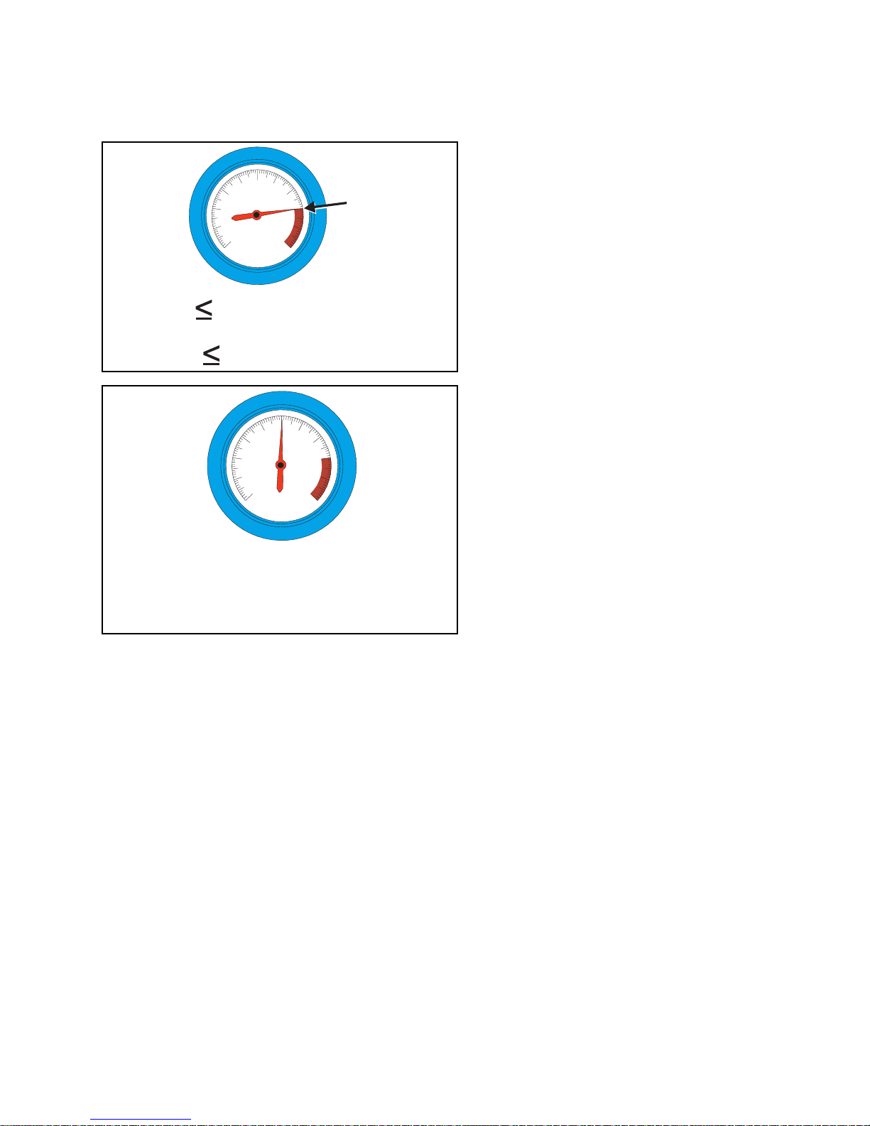
2.1.
Ensure the System Cannot Siphon.
—The supply system must be designed to
counteract any siphoning that could occur as a result of having a sealed supply line between the
bottom of the chemical tank and the internal machine connection at the drain trough. As shown in
the Figure 2 examples, if the pump (P) and/or the valving does not provide positive closure and
there is no vacuum breaker protection, siphoning is likely to occur. In each of the Figure 2
illustrations, the volume of chem ical in the tank abov e the siphon lev el (S), and indica ted by
shading, will flow into the machine.
PELLERIN MILNOR CORPORATION
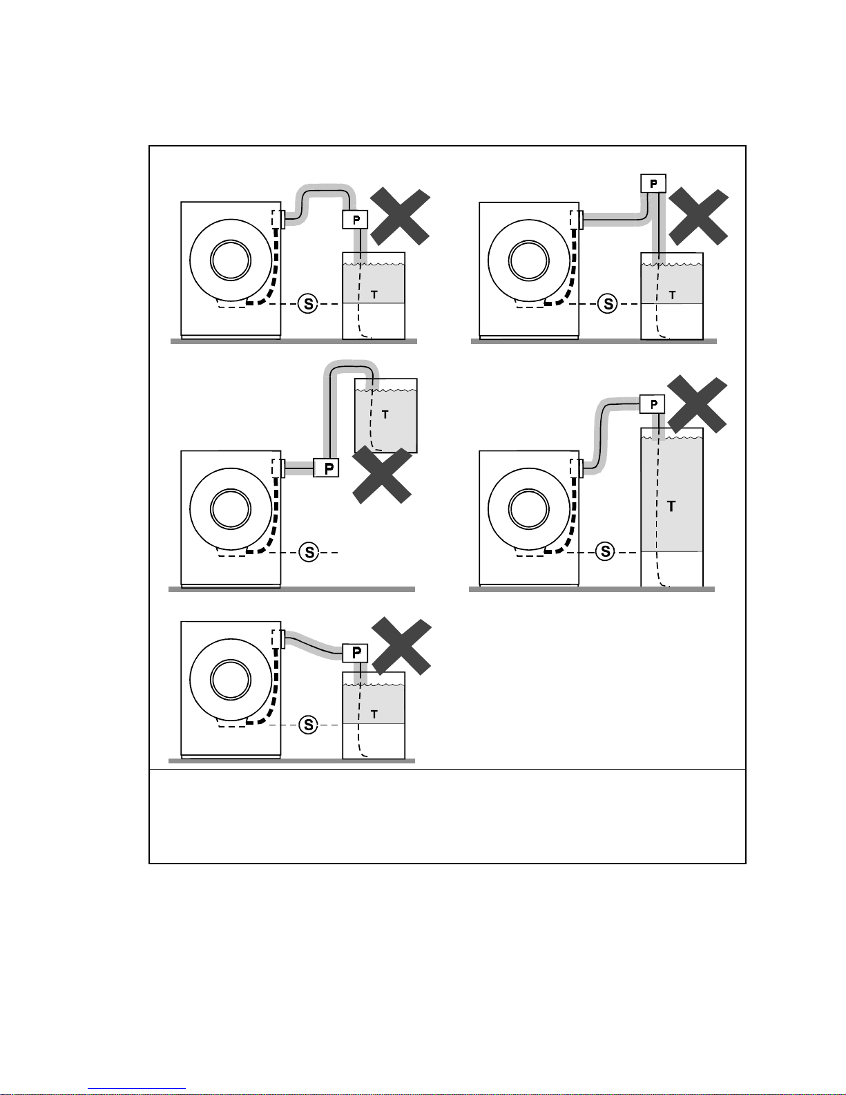
Figure 2:
Siphoning From the Chemical Tank into the Machine
Examples
Pump
P.
Siphon level. Shading indicates the chemical delivery line and tank content that can siphon into
S.
the machine.
Chemical tank
T.
2.2.
Ensure the Chemical Lines Cannot Dribble
provide a means of positively closing the chemical line at the pump location, but not at the
injection site. Hence, any concentrated chemical that remains in the injection line between the
pump and the machine is free to flow into the machine. Some examples of this are shown in
Figure 3.
Legend
—The pumped chemical system may
PELLERIN MILNOR CORPORATION
Avoiding Damage From Allied Remote Chemical Delivery Systems
Figure 3:
Dribbling From Chemical Supply Line Into Machine
(assumes positive closure at the pump)
Examples
Legend
Portion of supply line, the contents of which can dribble into the machine
D.
Pump
P.
Chemical tank
T.
3.
Design and Installation Recommendations
It is the responsibility of the chemical system manufacturer and supplier to use whatever
measures are necessary to ensure that their system is safe for personnel and equipment. The
following are some of the possible methods the manufacturer or supplier may wish to use, as
appropriate.
3.1.
Siphoning: Positively close the line.
—If the pump does not provide positive closure
when the system is off, employ a shutoff valve in the line to serve this purpose.
3.2.
Siphoning: Break the siphon.
—Provide an air gap or vacuum breaker in the chemical
delivery line. This must be located above the “full” line of the tank.
3.3.
Dribbling: Flush the entire chemical delivery line.
—If any concentrated chemical
that remains in the injection line between the pump and the machine is free to flow into the
machine, employ a system that flushes the entire line between the pump and the injection point
with fresh water after each injection.
PELLERIN MILNOR CORPORATION
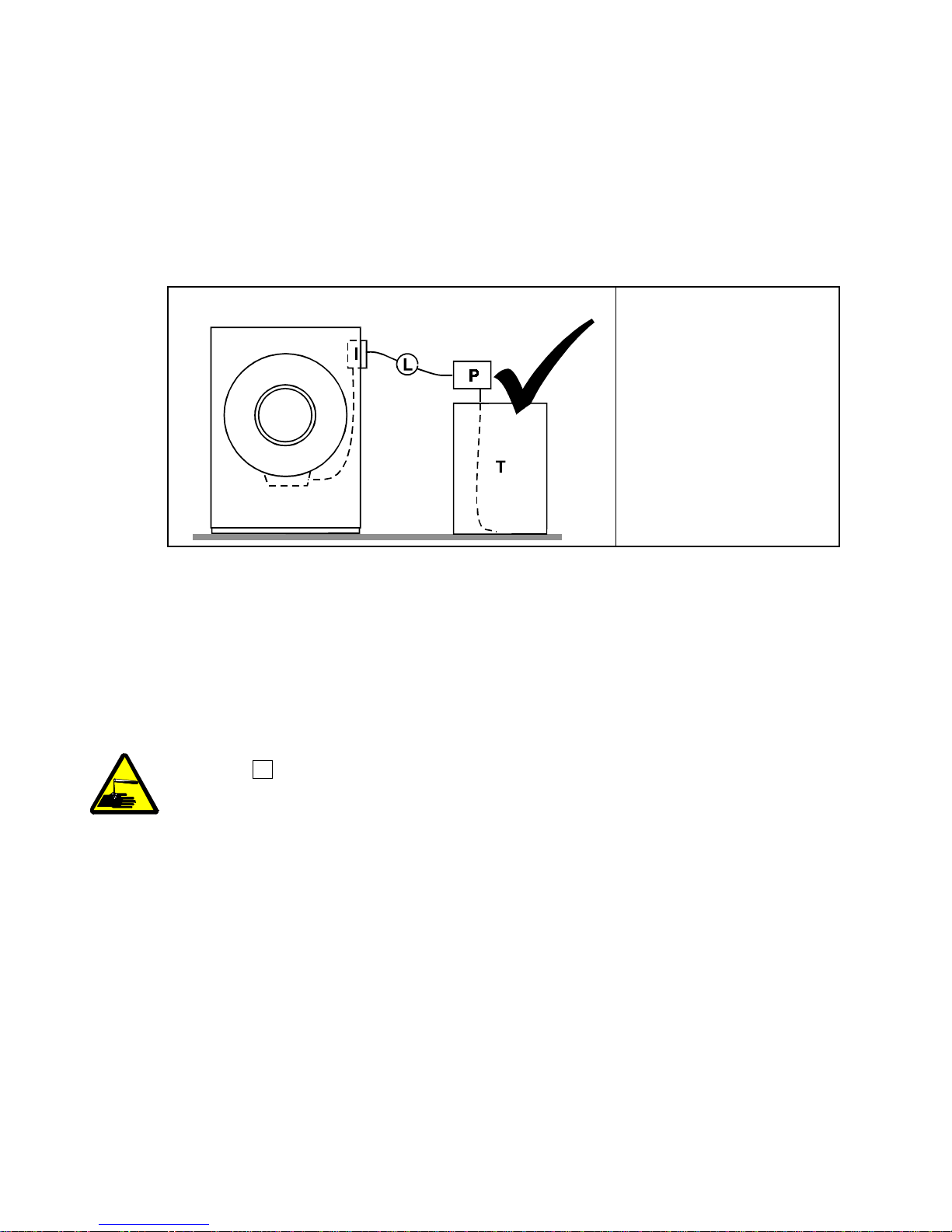
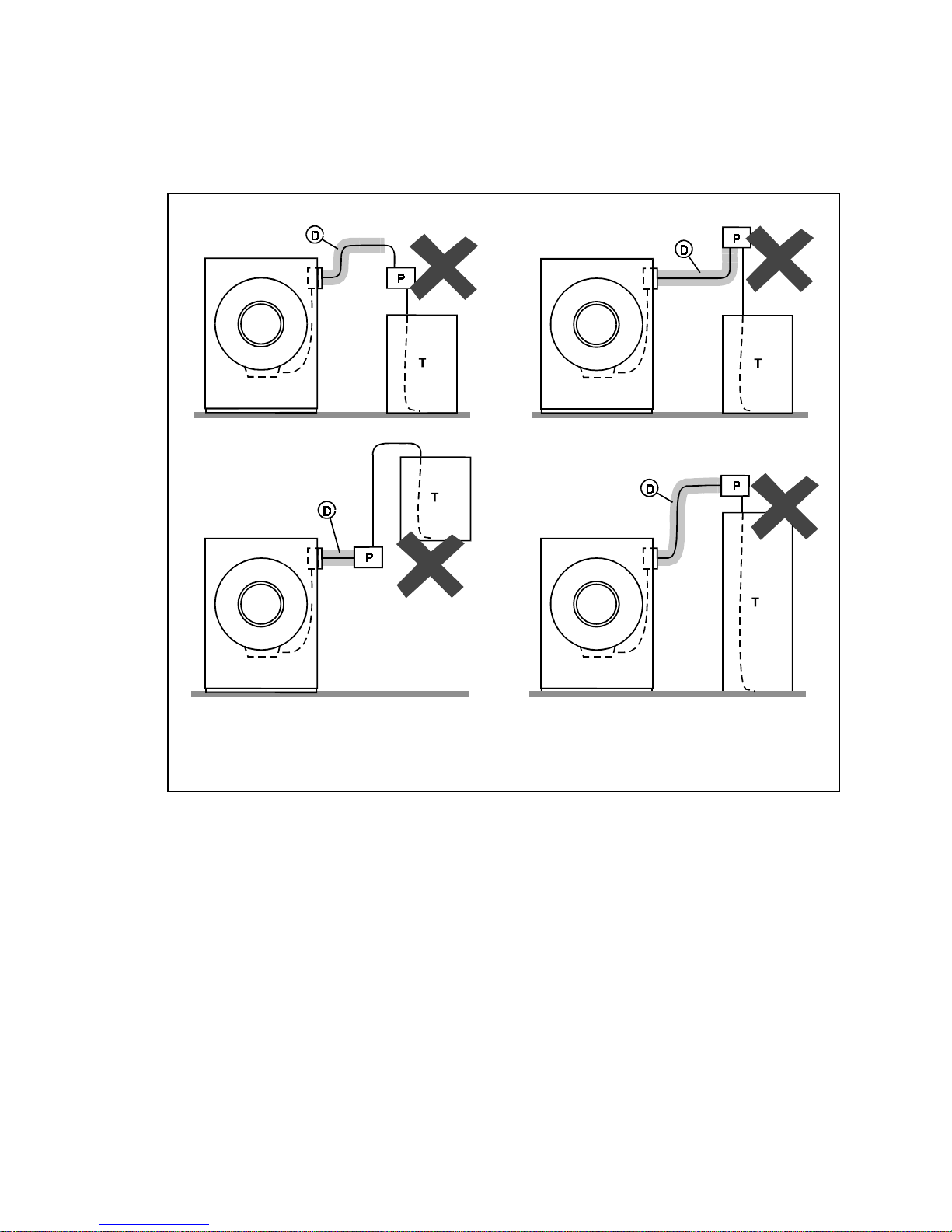
3.4.
Dribbling: Locate the entire chemical line below the machine inlet.
—
Assuming the chemical system does not retain any line pressure and that the pump provides
positive closure when the system is off, locate the entire chemical delivery line below the level of
the chemical inlet. An example of this is shown in Figure 4.
Figure 4:
Locating a Pumped Chemical System With Positive
Closure To Protect Against Machine Damage
Example of Correct Placement Legend
Chemical inlet on
I.
machine
Chemical delivery line
L.
Pump with positive
P.
closure when system is
off
Chemical tank
T.
4.
Guarding Against Leaks
All personnel who may work with the chemical system (e.g., chemical system manufacturer,
chemical system supplier, chemical supplier, operator, maintenance personnel) should be vigilant
in observing for leaks in the system. When connecting, or reconnecting chemical lines, whether at
installation, after taking samples, or when replacing components, at a minimum ensure that:
1. the proper components are used,
2. all connections are the proper fit, and
3. all components are securely connected.
CAUTION 2 : Injury and Damage Hazards
may be corrosive or toxic. Such chemicals can injure personnel and damage equipment.
• Use care when connecting chemical lines.
• Inspect regularly for leaks.
—Chemicals leaking from a chemical system
— End of BIWUUI03 —
PELLERIN MILNOR CORPORATION

BIRUUI01 (Published) Book specs- Dates: 20050221 / 20050221 / 20050221 Lang: ENG01 Applic: RCU
Handling and Setting Procedures for Rigid Mount WasherExtractors
1. Handling Precautions
1. Remove the protective coverings (leaving the machine on shipping skids) and carefully
examine for possible shipping damage. If the machine is damaged, notify the
transportation company immediately.
Note 1: Once the machine is given to the carrier for delivery, it is the sole responsibility of the carrier
to ensure that no damage occurs during transit. In addition to readily apparent damage, carriers are
liable for concealed damage. Do not hesitate to file a claim with the carrier if the machine is
damaged in any way during shipment. Milnor® will be glad to assist you in filing your claim, but is
not responsible for any shipping damage to the machine once it has been delivered to the carrier in
good condition.
2. Consult Milnor® for instructions if crane lifting is required.
3. Use skids with the forklift. If possible, leave the machine on the shipping skids until it is
about to be placed in its final position. Once the skids are removed, take care in placing forks
under the machine. Do not allow the forks to come in contact with valves, piping, motors,
etc., located under the machine.
4. Never push, pull, or exert pressure on any components that protrude from the machine frame
(shell front, door, supply injector, electric boxes, controls, belt guard, conduits, inlet piping,
etc.).
5. Ensure that the shell door is closed and secured.
2. Site Requirements
2.1. Space Requirements
1. All openings and corridors through which equipment must pass during installation must be
large enough to accommodate the width and the height of the machine (as shown on the
dimensional drawings). It is occasionally possible to reduce the overall dimensions by
removing piping or other special modifications. Consult Milnor® for additional information.
2. Sufficient clearance must be provided for normal operation and maintenance procedures.
2.2. Operational Requirements
1. Allow sufficient ventilation for heat and vapors of normal operation to dissipate.
2. Provide easy access to controls. Operators must be able to reach and view all status lights,
machine controls, and any additional controls associated with the machine (e.g., electrical
power connections, water and steam shut-offs, etc.).
2.3. Foundation Requirements—The machine must be anchored in accordance with the
installation instructions. The floor and/or all other support components must have sufficient
strength (and rigidity with due consideration for the natural or resonant frequency thereof) to
withstand the fully loaded weight of the machine, including the wet goods and any repeated
sinusoidal (rotating) forces generated during its operation. Determining the suitability of floors,
foundations, and other supporting structures normally requires analysis by a qualified structural
engineer. See “ABOUT THE FORCES TRANSMITTED BY MILNOR® WASHEREXTRACTORS” (See Table of Contents) for more information.
PELLERIN MILNOR CORPORATION

Handling and Setting Procedures for Rigid Mount Washer-Extractors
y
3. Anchoring Requirements
Machines must be securely anchored to an adequate pedestal base (supplied by others) or a
concrete foundation. The bolt holes in the pedestal top flange should be located and drilled only
after the machine is on site and can be used as a template for bolt hole locations (See the pedestal
base dimensional drawings in this manual). Customer must determine location of bolt holes in
bottom flange if the machine is to be bolted to a foundation. Foundation templates are available
for some machines. Consult Milnor if any obstruction prevents the installation of any anchor bolt.
Properly install anchor bolts at ALL anchor bolt holes on the machine. Anchor bolts cannot
be indiscriminately omitted.
CAUTION 1 : STRIKE AND MACHINE DAMAGE HAZARDS—A machine can “rip”
from its foundation if the machine is not anchored andgrouted in strict accordance with the
awa
dimensional drawing and setting instructions provided in this manual. Damage resulting from
improper installation is not covered by warranty.
• Strictly follow setting instructions and dimensional drawing guidelines when anchoring
and setting this machine.
4. Setting Procedures
1. With the machine near the final location, unbolt the shipping skids.
• If using a pedestal mount (and after observing all precautions), lift machine level with top
of pedestal and slide onto pedestal. Bolt or weld machine to pedestal as desired (See the
pedestal base dimensional drawings for additional information).
• If using a foundation (and after observing all precautions), lift the machine off the skid
and onto temporary blocking. Install anchor bolts, taking care to align the bolts with the
base plates to avoid bolt thread damage. Determine that the minimum clearance
between each base plate and floor surface is as specified (see dimensional drawings).
Shim the machine at temporary blockings to level the machine from left to right and front
to back. Use a carpenter's level along the right and left side of the base to determine if the
machine is level from front to back. Place a level laterally across the base plates to
determine if the machine is level from right to left then see the grouting instructions
below.
CAUTION 2 : MACHINE DAMAGE AND MALFUNCTION HAZARDS—
Tightening anchor bolt fasteners onto spacers (without grout or with improperly applied
grout) twists the machine frame and causes cylinder misalignment.
• Never tighten anchor bolt fasteners before grouting.
• Grout must displace total clearance between base plate and existing foundation
floor. Voids must not exist!
1. After determining the final position of the machine, apply grout between the existing
foundation floor and base, while observing the following considerations:
• All machines are designed to be grouted under the full area of all base plates.
Grout prevents the anchor bolts from distorting the frame when the fasteners are
tightened. Total area under each base plate must be completely filled with grout
(see dimensional drawings). Voids under base plates can magnify vibration,
causing unsatisfactory operation. Use only industrial strength non-shrinking
grout.
• If the grout (after mixing) is of proper consistency, pack or trowel it by hand.
PELLERIN MILNOR CORPORATION

• If the grout (after mixing) is too thin (causing it to flow from under the base
pads), install temporary cardboard framing around the pads to retain the grout
until it cures.
2. After the grout has completely cured, raise the machine sufficiently to remove all
temporary blocking and shims. Be careful to avoid disturbing or damaging grout.
3. Lower machine onto grout and tighten all foundation fasteners until they contact the
top of the base plate.
2. Tighten all fasteners evenly, using only one-quarter turn on each fastener before moving to
the next one. While tightening, frequently skip from front to back and right to left to insure
uniform tension. After tightening all fasteners, check each fastener at least twice.
— End of BIRUUI01 —
PELLERIN MILNOR CORPORATION
 Loading...