

Page 1
Published Manual Number/ECN: MATMLTRCAE/2018103A
• Publishing System: TPAS2
• Access date: 03/06/2018
• Document ECNs: Latest
Technical Reference
Miltrac™ Controller
PELLERIN MILNOR CORPORATION POST OFFICE BOX 400, KENNER, LOUISIANA 70063-0400, U.S.A.
Page 2

Page 3

Table of Contents
MATMLTRCAE/18103A
Page Description Document
1 Limited Standard Warranty BMP720097/2008272A
2 How to Get the Necessary Repair Components BIUUUD19/20081231
3 Trademarks BNUUUU02/2017285A
4 Comments & Suggestions MHTCMMNTAE/199816V
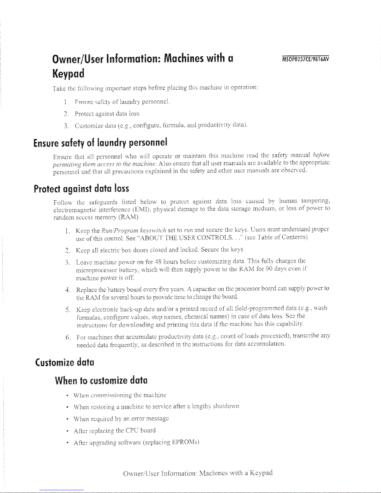
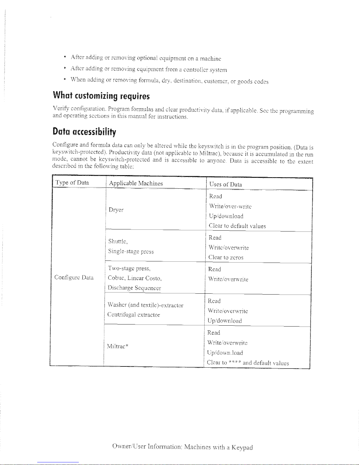
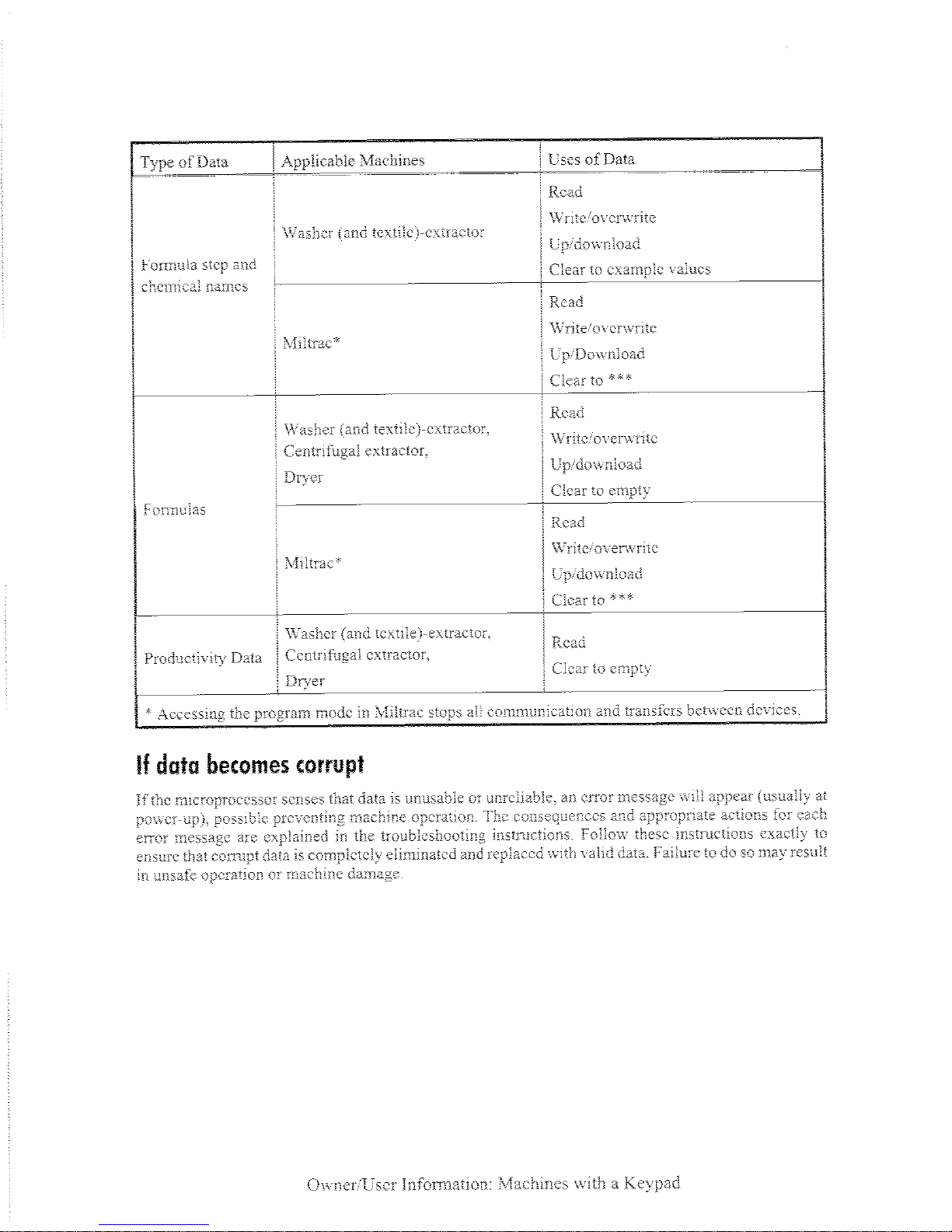
5 Owner/User Information: Machines with a Keypad MSOP0237CE/199816AV
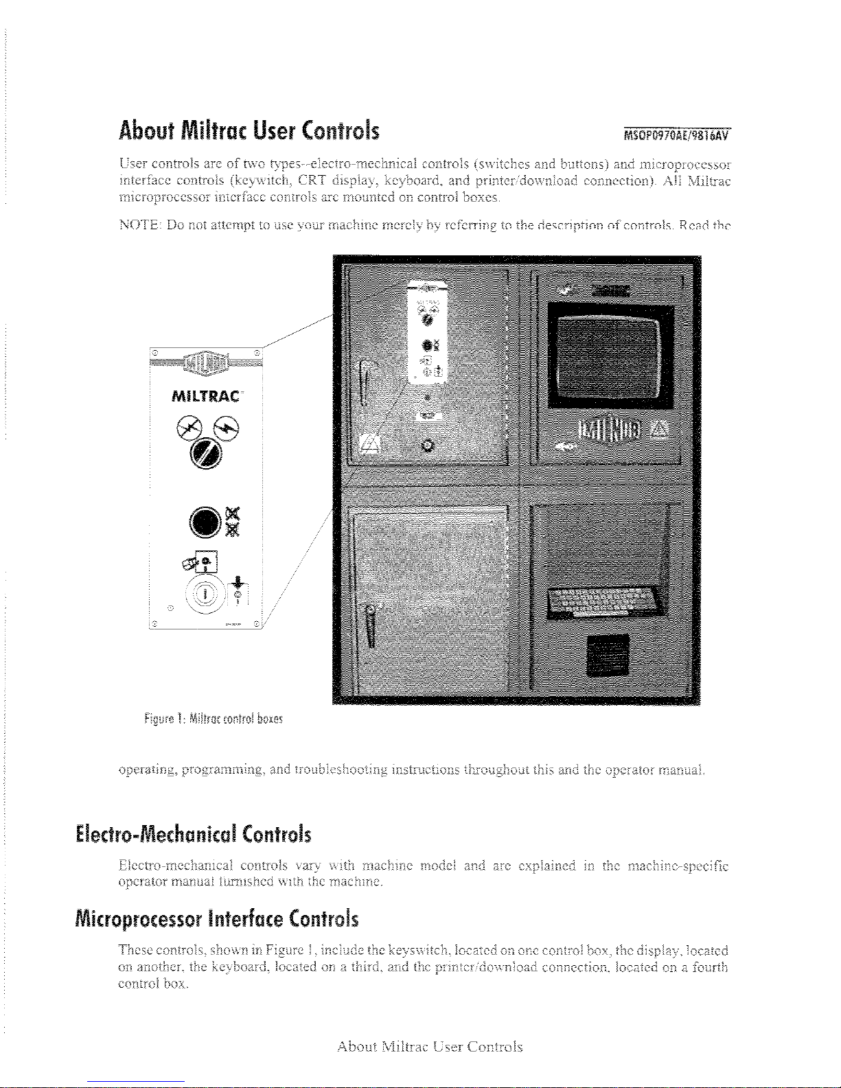
8 About Miltrac User Controls MSOP0970AE/199816AV
10 Overview of Miltrac MSOP0968AE/199816AV
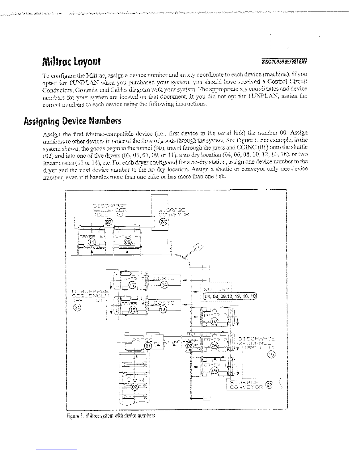
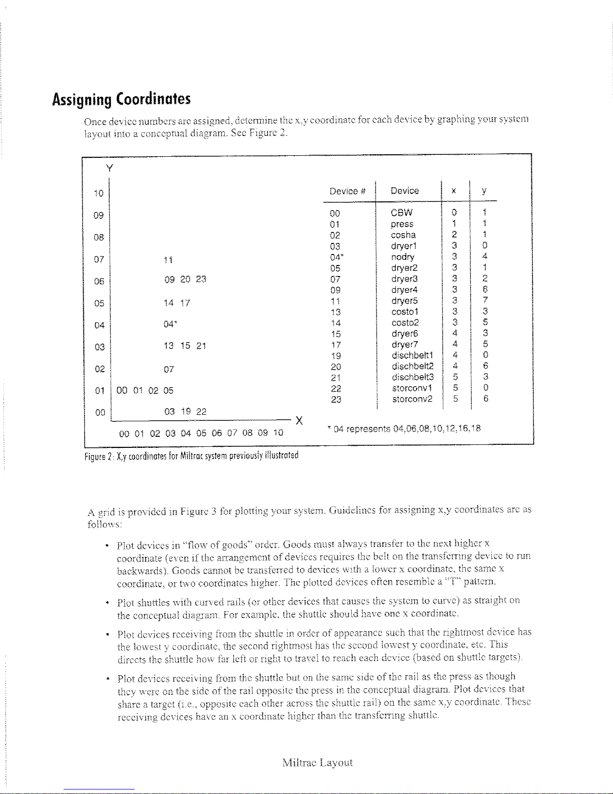
11 Miltrac Layout MSOP0969BE/199816AV
15 1. Programming
16 Programming Miltrac: Overview MSOP0971AE/199816AV
22 Programming Miltrac: Initialize and Exit MSOP0972AE/199816AV
29 Programming Miltrac: Configure MSOP0973AE/199816AV
40 Stuffing Logic for the Miltrac Controller BIYCMC03/20150108
41 Programming Miltrac: Display Pages MSOP0974AE/199816AV
45 Programming Miltrac: Names MSOP0975AE/199816AV
47 2. Supplemental Information
48 Monitoring with Miltrac MSOP0976AE/199816AV
55 Memory Download Box Applications BICUDC01/20010807
59 3. Troubleshooting
60 Troubleshooting Miltrac MSOP0977AE/199816AV
Page 4

Page 5

PELLERIN MILNOR CORPORATION
LIMITED STANDARD WARRANTY
We warrant to the original purchaser that MILNOR machines including electronic
hardware/software (hereafter referred to as “equipment”), will be free from defects in material and
workmanship for a period of one year from the date of shipment (unless the time period is specifically
extended for certain parts pursuant to a specific MILNOR published extended warranty) from our
factory with no operating hour limitation. This warranty is contingent upon the equipment being
installed, operated and serviced as specified in the operating manual supplied with the equipment,
and operated under normal conditions by competentoperators.
Providing we receive written notification of a warranted defect within 30 days of its discovery, we
will at our option repair or replace the defective part or parts, FOB our factory. We retain the right to
require inspection of the parts claimed defective in our factory prior to repairing or replacing same.
We will not be responsible, or in any way liable, for unauthorized repairs or service to our equipment,
and this warranty shall be void if the equipment is tampered with, modified, or abused, used for
purposes not intended in the design and construction of the machine, or is repaired or altered in any
way without MILNOR's written consent.
Parts damaged by exposure to weather, to aggressive water, or to chemical attack are not covered by
this warranty. For parts which require routine replacement due to normal wear such as gaskets,
contact points, brake and clutch linings, belts, hoses, and similar parts the warranty time period is 90
days.
We reserve the right to make changes in the design and/or construction of our equipment (including
purchased components) without obligation to change anyequipmentpreviouslysupplied.
ANY SALE OR FURNISHING OF ANY EQUIPMENT BY MILNOR IS MADE ONLY UPON
THE EXPRESS UNDERSTANDING THAT MILNOR MAKES NO EXPRESSED OR IMPLIED
WARRANTIES OF MERCHANTABILITY OR FITNESS FOR ANY PARTICULAR USE OR
PURPOSE
LIMITED TO REDHIBITION
DAMAGES ACTUALLY INCURRED OR REQUIRED AS A RESULT OF: THE FAILURE OF
ANY OTHER PERSON OR ENTITY TO PERFORM ITS RESPONSIBILITIES, FIRE OR
OTHER HAZARD, ACCIDENT, IMPROPER STORAGE, MIS-USE, NEGLECT, POWER OR
ENVIRONMENTAL CONTROL MALFUNCTIONS, DAMAGE FROM LIQUIDS, OR ANY
OTHER CAUSE BEYOND THE NORMAL RANGE OF USE. REGARDLESS OF HOW
CAUSED, IN NO EVENT SHALL MILNOR BE LIABLE FOR SPECIAL, INDIRECT,
PUNITIVE, LIQUIDATED, OR CONSEQUENTIAL COSTS OR DAMAGES, OR ANY COSTS
OR DAMAGES WHATSOEVER WHICH EXCEED THE PRICE PAID TO MILNOR FOR THE
EQUIPMENT ITSELLSORFURNISHES.
THE PROVISIONS ON THIS PAGE REPRESENT THE ONLY WARRANTY FROM MILNOR
AND NO OTHER WARRANTY OR CONDITIONS, STATUTORY OR OTHERWISE, SHALL
BE IMPLIED.
OR ANY OTHER WARRANTY IMPLIED BY LAW INCLUDING BUT NOT
. MILNOR WILL NOT BE RESPONSIBLE FOR ANY COSTS OR
WE NEITHER ASSUME, NOR AUTHORIZE ANY EMPLOYEE OR OTHER PERSON TO
ASSUME FOR US, ANY OTHER RESPONSIBILITY AND/OR LIABILITY IN CONNECTION
WITH THE SALE OR FURNISHING OF OUR EQUIPMENT TOANYBUYER.
BMP720097/2008272A
1
Page 6

How to Get the Necessary Repair Components
BIUUUD19 (Published) Book specs- Dates: 20081231 / 20081231 / 20081231 Lang: ENG01 Applic: UUU
How to Get the Necessary Repair Components
This document uses Simplified Technical English.
Learn more at http://www.asd-ste100.org.
You can get components to repair your machine from the approved supplier where you got this
machine. Your supplier will usually have the necessary components in stock. You can also get
®
components from the Milnor
factory.
Tell the supplier the machine model and serial number and this data for each necessary component:
• The component number from this manual
• The component name if known
• The necessary quantity
• The necessary transportation requirements
• If the component is an electrical component, give the schematic number if known.
• If the component is a motor or an electrical control, give the nameplate data from the used
component.
To write to the Milnor factory:
Pellerin Milnor Corporation
Post Office Box 400
Kenner, LA 70063-0400
UNITED STATES
Telephone: 504-467-2787
Fax: 504-469-9777
Email: parts@milnor.com
— End of BIUUUD19 —
PELLERIN MILNOR CORPORATION
2
Page 7

BNUUUU02 / 2017285A BNUUUU02 0000158094 A.3 7/13/17 1:53 PM Released
Trademarks
BNUUUU02.R01 0000158093 A.2 7/13/17 1:11 PM Released
These words are trademarks of Pellerin Milnor Corporation and other entities:
Table 1 Trademarks
AutoSpot™ GreenTurn™
CBW®
Drynet™
E-P Express®
GreenFlex™ MilMetrix® PurePulse®
Hydro-cushion™ MilTouch™ Ram Command™
Linear Costa Master™ MilTouch-EX™ RecircONE®
Milnor® PulseFlow®
E-P OneTouch® Linear Costo™ Miltrac™ RinSave®
E-P Plus®
Gear Guardian® Mildata®
Mentor®
MultiTrac™ SmoothCoil™
PBW™
End of document: BNUUUU02
Staph Guard®
Pellerin Milnor Corporation
3
Page 8
4
Page 9
5
Page 10
6
Page 11
7
Page 12
8
Page 13
9
Page 14
10
Page 15
Page 16
12
Page 17
Page 18

Page 19

Programming 1
15
Page 20
Page 21

17
Page 22

18
Page 23

19
Page 24

20
Page 25

Page 26

Page 27

23
Page 28

24
Page 29

25
Page 30

26
Page 31

Page 32

28
Page 33

Page 34

Page 35

Page 36

Page 37

Page 38

Page 39

Page 40

Page 41

Page 42

Page 43

Page 44

Stuffing Logic for the Miltrac Controller
BIYCMC03 (Published) Book specs- Dates: 20150108 / 20150108 / 20150108 Lang: ENG01 Applic: YCM
Stuffing Logic for the Miltrac Controller
The Miltrac controller uses stuffing logic to arrange cakes of goods so the receiving device is
always loaded at its maximum capacity with compatible goods. The most common application is
when dryers are loaded by Linear Costa devices. Other applications include multi-cake shuttles
loaded by Linear Costa devices.
For example, assume that two dryers can each process two cakes. Each dryer is loaded by a
Linear Costa device. If one of the Linear Costa devices already contains one cake, the Miltrac
controller will sequentially check each cake for compatibility with the already-loaded cake. The
Miltrac controller will send the first compatible cake to the Linear Costa device that already
contains a cake to make a full load for the dryer.
1. How to Enable Stuffing Logic
On the MilTrac controller System Configure page:
1. Set Stuffing Logic = 1.
2. Set X Coordinate to be Stuffed = [X-coordinate for the Linear Costa devices]
3. Set Number of Cakes per Batch = [maximum number of cakes per dryer load]
On the Miltrac controller Device Configure page, set Compatibility for the Linear Costa devices.
Stuffing logic uses compatibility attributes to match cakes together for a load.
2. Other Guidelines
Follow these guidelines if there are problems with stuffing logic:
• Set the value for X Coordinate to be Loaded to a value OTHER THAN the X-coordinate of
the Linear Costa devices.
• Set the value for X Coordinate to be Discharged to a value OTHER THAN the X-coordinate
of the Linear Costa devices.
• Set the shuttle configuration value for Hold Unld Device Til Full = 0.
— End of BIYCMC03 —
PELLERIN MILNOR CORPORATION
40
Page 45

Page 46

Page 47

Page 48

44
Page 49

Page 50

46
Page 51

Supplemental Information 2
47
Page 52

Page 53

49
Page 54

Page 55

Page 56

Page 57

Page 58

Page 59

=U]_bi 4_g^\_QT 2_h 1``\YSQdY_^c
p
7
7
7
D
<T\^ah3^f][^PS1^g0__[XRPcX^]b
The memory download box is used to store configuration and formula data for most current
models of Milnor
Transmit
button on the front panel, and one without the button. The
required for machines—usually CBW
initiating the data transfer.
Figure 1: Download Box Identification
®
machines. Two types of download boxes (Figure 1) are available: one with a
®
controllers and similar devices—which are capable of
Faceplate Comparison
Document..................... BICUDC01
ecified Date................. 2001080
S
As-of Date....................... 2001080
Access Date..................... 2001080
Applicability.................. YUD CU
Language Code.................... ENG01
Transmit
button is not
1. Download box with Transmit button
2. Download box without Transmit button
3. Transmit button
4. Key switch
Legend
55
Page 60

=U]_bi 4_g^\_QT 2_h 1``\YSQdY_^c
Figure 2: Rear View of Circuit Board
View Legend
1. DIP switch
2. Software chip
3. Location of Transmit
button, if equipped
4. Key switch
Bd__[T\T]c
8]cTa_aTcX]V cWT 38? BfXcRW BTccX]Vb
Use the following codes and their definitions to set the DIP switch positions for the equipment,
as shown in Table 1.
A. All switch positions are OFF.
B. Switch position 4 is ON; all other switch positions are OFF.
C. Switch position 5 is ON; all other switch positions are OFF.
D. Switch positions 1 and 5 are ON; all other switch positions are OFF.
=^cT )
configuration and formula data from any machine that's capable of downloading. When using a buttonequipped download box to store data from one of the devices listed in Table 1 as requiring the Transmit
button, ignore the button. The download will begin when commanded from the device control panel.
If necessary, a memory download box with the Transmit button may be used to store
56
Page 61

Table 1: DIP Switch Positions
Processor
Board Software Version
DIP Switch
Setting
=U]_bi 4_g^\_QT 2_h 1``\YSQdY_^c
Processor
Board Software Version
DIP Switch
Setting
Uses Memory Download Box WITH Transmit
Button
Uses Memory Download Box WITHOUT
Transmit Button
Washer-extractor Models Miltron Controller for CBW System
8088 All C 8088 All A
98000-98003 C 80186 All B
98004-99004 not supported Miltrac
80186
99005-9900B D 8088 All A
20000-20003 D 80186 All B
FxW, FxP, and FxS Washer-extractor models Milrail Rail Controller
8088 All C 8088 All A
98000-98003 C 80186 All B
98004-98009 not supported Device Master
80186
9800A-9800H D 8085 All not supported
20000-2000B D 8088 All not supported
Textile and Dye Machine Models 94000-94017 not supported
8088 All C 94018 B
95000-95305M C
80186
20000-present B
95305N-95306 D Linear Costo Master80186
20000-20004 D 8085 All not supported
Dryer Models 8088 All not supported
8088 All C 94000-94011 not supported
80186
80186 All C
20000-present B
Centrifugal Extractor Models Key:
8088 All C A All switch positions OFF
80186 All C B Position 4 ON; all others OFF
Single-station Press Models C Position 5 ON; all others OFF
8088 All C D Positions 1 and 5 ON; all others OFF
— End of BICUDC01 —
57
Page 62

Page 63

Troubleshooting 3
59
Page 64

60
 Loading...