

Milnor EX-15 ES, EX-25 ES, EX-15, EX-25 Maintance Manual
WARNING: ALL OPERATING AND MAINTENANCE PROCEDURES SHOWN ON THE NEXT
PAGE OF THIS MANUAL MUST BE FOLLOWED DAILY FOR PROPER OPERATION OF
YOUR WASCOMAT MACHINE.
PLEASE ENTER THE FOLLOWING INFORMATION AS IT APPEARS ON THE MACHINE(S)
DATA PLATE(S).
MAKE CERTAIN TO KEEP THIS MANUAL IN A SECURE PLACE FOR FUTURE
REFERENCE.
MACHINE TYPE OR MODEL
MACHINE SERIAL NUMBER(S)
ELECTRICAL CHARACTERISTICS:________ VOLTS, _______ PHASE, ______ HZ.
OPERATING & MAINTENANCE MANUAL
EX-15 and EX-25
Emerald Series
438 9030-01/02
97.02

NOTICE TO: OWNERS, OPERATORS AND DEALERS OF WASCOMAT MACHINES
II
IMPROPER INSTALLATION AND INADEQUATE MAINTENANCE, POOR HOUSEKEEPING AND WILLFUL
NEGLECT OR BYPASSING OF SAFETY DEVICES MAY RESULT IN SERIOUS ACCIDENTS OR INJURY.
TO ASSURE THE SAFETY OF CUSTOMERS AND/OR OPERATORS OF YOUR MACHINE, THE FOLLOWING MAINTENANCE CHECKS MUST BE PERFORMED ON A DAILY BASIS.
1. Prior to operation of the machine, check to make certain that all operating instructions and
warning signs are affixed to the machine and legible. (See the following page of this manual
for description and location of the signs.) Missing or illegible ones must be replaced immediately. Be sure you have spare signs and labels available at all times. These can be obtained from your dealer or Wascomat.
2. Check the door safety interlock, as follows:
(a) OPEN THE DOOR of the machine and attempt to start in the normal manner:
For coin-operated models, select a wash cycle, insert the proper coins and press the
START button.
For manually operated models, select a wash cycle and press the START button.
THE MACHINE(S) SHOULD NOT START !
(b) CLOSE THE DOOR to start machine operation and, while it is operating, attempt to
open the door without exerting extreme force on the door handle. The door should
remain locked!
If the machine can start with the door open, or can continue to operate with the door
unlocked, the door interlock is no longer operating properly. The machine must be
placed out of order and the interlock immediately repaired or replaced.(See the door
interlock section of the manual.)
3. DO NOT UNDER ANY CIRCUMSTANCES ATTEMPT TO BYPASS OR REWIRE ANY OF
THE MACHINE SAFETY DEVICES AS THIS CAN RESULT IN SERIOUS ACCIDENTS.
4. Be sure to keep the machine(s) in proper working order: Follow all maintenance and
safety procedures. Further information regarding machine safety, service and parts can be
obtained from your dealer or from Wascomat through its Teletech Service Telephone - 516/
371-0700.
All requests for assistance must include the model, serial number and electrical characteristics as
they appear on the machine identification plate. Insert this information in the space provided on the
previous page of this manual.
5. WARNING: DO NOT OPERATE MACHINE(S) WITH SAFETY DEVICES BYPASSED, REWIRED OR
INOPERATIVE! DO NOT OPEN MACHINE DOOR UNTIL DRUM HAS STOPPED ROTATING!

CAUTION
1. Do not open washer door until cycle is completed, operating
light is off, and wash cylinder has stopped rotating.
2. Do not tamper with the door safety switch or door lock.
3. Do not attempt to open door or place hands into washer to
remove or add clothes during operation. This can cause
serious injury.
MACHINE SHOULD NOT BE USED BY CHILDREN
PRECAUCION
1. No abra la puerta de la máquina lavadora sino hasta que la
máquina haya terminado su ciclo, la luz operativa esté apaga
da y el cilindro de lavado haya completamento terminado de
girar.
2. No interferia o manipule el switch o la cerradura de la puerta.
3. No trate de abrir la puerta o meta las manos dentro de la
máquina para meter o sacar ropa mientras la máquina está
en operación, pues puede resultar seriamento herido.
LAS MÁQUINAS NO DEBEN SER USADAS POR NIÑOS
SAFETY AND WARNINGS SIGNS
Replace If Missing Or Illegible
One or more of these signs must be affixed on each machine as indicated, when not included as part of the front instruction panel.
LOCATED ON THE OPERATING INSTRUCTION SIGN OF THE MACHINE:

Contents
Introduction ......................................................................1
Technical data.................................................................. 2
Installation ........................................................................5
Safety rules .................................................................... 12
Operating instructions .................................................... 13
Programming..................................................................19
Wash cycles ...................................................................22
Mechanical and electrical design ................................... 31
Serviceprogram.............................................................. 55
Trouble shooting ............................................................58
Maintenance...................................................................83
Safety instructions
• This machine is designed for water washing only.
• This machine must not be used by children.
• All installation operations are to be carried out by qualified
personnel. Licensed personnel are necessary for all electric
power wiring.
• The interlock of the door must be checked daily for proper
operation and must not be bypased.
• All seepage in the system, due to faulty gaskets etc., must be
repaired immediately.
• All service personnel must be fully familiar with the operating
manual before attempting any repair or maintenance of the
machine.
• This machine must not be sprayed with water, otherwise short
circuiting may occur.
• Fabric softeners with volatile or inflammable fluids are not to
be used in the machine.
The manufacturer reservs the right to make changes to design and
material specifications.
EX-15 ES, EX-25 ES
1
3317
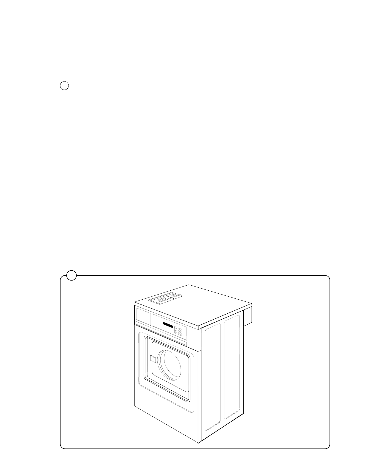
Introduction
The washer-extractors described in this manual are high-speed extract machines
with built-in wash programs. They are designed for use in applications such as
apartment-house laundries, hotels, commercial laundries, in industry, hospitals,
small institutions, and by other users who require a machine with a high level of
reliability, good performance and easy maintenance.
The drum assembly on these models is of the suspended type, in other words not
rigidly mounted on the machine base. This means that a minimum of vibration is
transferred to the frame, which in turn simplifies installation as no concrete
foundation is required.
Vibration due to imbalance is further reduced because the drum begins the
extraction cycle at distribution speed, to distribute the load before extraction at
high speed.
The high extraction speed of the drum produces a G factor of approx. 300, which
ensures a high degree of water extraction.
The machine has an electronic program control unit with built-in wash programs
which can be modified through the use of option buttons. The program control
unit also includes a built-in service program to assist in tracing faults quickly and
efficiently.
The frequency-controlled motor is controlled by an advanced motor control unit.
This means that the motor speed can be controlled with precision and flexibility at
every stage in the program.
The machines are equipped according to customer requirements, with the option
of electric or steam heating. The water intake can be adapted for various
combinations of cold, hot and hard water supply.
Introduction
1
Fig.
1

2
Technical data EX-15 ES
Dry load capacity up to 15 lbs
Overall dimensions Width 720 mm 28 11/32 in
Depth 660 mm 26 in
Height 1100 mm 43 5/16 in
Net weight 169 kg 373 lbs
Maximum floor load 1.6 ± 0.7 kN 390 ± 170 lbs force
Crated dimensions Volume 0.66 m
3
23.3 cu.ft
Weight 181 kg 399 lbs
Inner drum dimensions Diameter 520 mm 20 1/2 in
Depth 310 mm 12 3/16 in
Volume 65 litre 2.3 cu.ft
Drum speed Wash 48 rpm
Distribution 90 rpm
Extraction 550/700/1020 rpm
G-factor During wash 0.8
During extraction 300
Motor speed During wash 415 rpm
During distribution 780 rpm
During extraction 4760/6060/8820 rpm
Voltage requirements 120 V 1-Phase 60 Hz or 208-240 60-1
Rated output power Max. Frequency controlled motor 700 W 0.9 HP
0-90 VAC 0-250 Hz
Overcurrent protection 15 A
Water connections Rec. pressure 2-6 kp/cm
2
25-85 psi
Hose connection, water DN 20 3/4 in
Drain connection Hose 50 mm 2 in
Technical data

3
Technical data EX-25 ES
Dry load capacity up to 25 lbs
Overall dimensions Width 720 mm 28 11/32 in
Depth 820 mm 32 9/32 in
Height 1100 mm 43 5/16 in
Net weight 255 kg 562 lbs
Maximum floor load 2.5 ± 0.95 kN 598 ± 232 lbs force
Crated dimensions Volume 0.77 m
3
27.2 cu.ft
Weight 270 kg 595 lbs
Inner drum dimensions Diameter 520 mm 20 1/2 in
Depth 470 mm 18 1/2 in
Volume 100 litre 3.5 cu.ft
Drum speed Wash 48 rpm
Distribution 90 rpm
Extraction 550/700/1020 rpm
G-factor During wash 0.8
During extraction 300
Motor speed During wash 415 rpm
During distribution 780 rpm
During extraction 4760/6060/8820 rpm
Voltage requirements 120 V or 208-240 V 1- Phase 60 Hz
Rated output power Max. Frequency controlled motor 1500 W 2.0 HP
0-90 VAC 0-250 Hz
Overcurrent protection 20 A at 120 V
15 A at 208-240 V
Water connections Rec. pressure 2-6 kp/cm
2
25-85 psi
Hose connection, water DN 20 3/4 in
Drain connection Hose 50 mm 2 in
Technical data
4
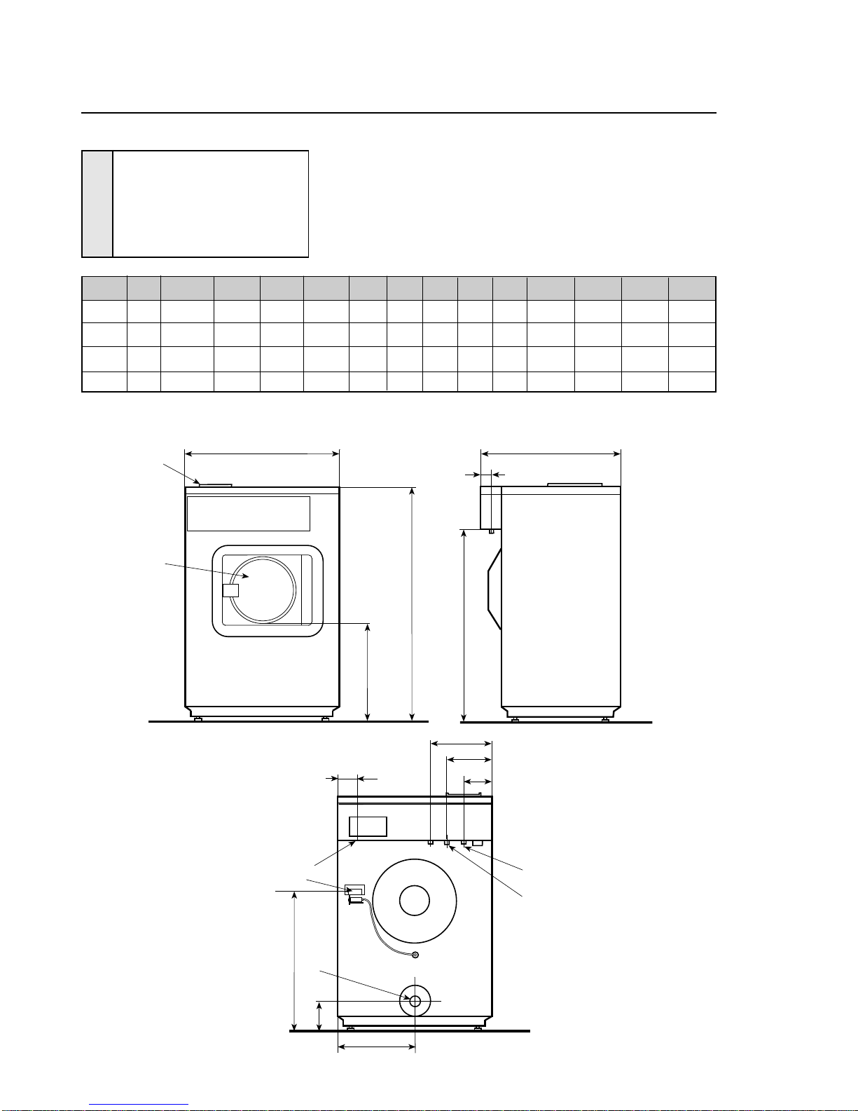
1 Door opening ø290 mm/11 7/16"
2 Soap box
3 Water connections (Hot and cold)
4 Electrical connection
5 Drain Ø 50 mm/2"
6 Steam connection 1/2" (optional)
M
3
3
K
H
F
4
6
3137
I
Right side
Front
ABCDEFGHIKLMN
EX-15 mm 720 660 1100 440 905 60 60 130 235 290 150 360 630
inch 28 11/32 26 43 5/16 17 5/16 35 5/8 2 3/8 2 3/8 5 1/8 9 1/4 11 7/16 5 29/32 14 5/32 24 13/16
EX-25 mm 720 820 1100 440 905 60 60 130 235 290 150 360 630
inch 28 11/32 32 9/32 43 5/16 17 5/16 35 5/8 2 3/8 2 3/8 5 1/8 9 1/4 11 7/16 5 29/32 14 5/32 24 13/16
2
1
AB
G
D
C
E
Rear side
L
5
N
Technical data
Installation
The machines are free-standing, i.e. the drum
can move relative to the frame of the machine.
This results in a considerable reduction in vibration transferred to the frame which in turn
simplifies installation: no special foundation is
required.
The machine is delivered complete with expansion bolts etc. packed inside the drum. Move the
machine on its pallet to where it is to be installed
before removing the pallet retaining bolts.
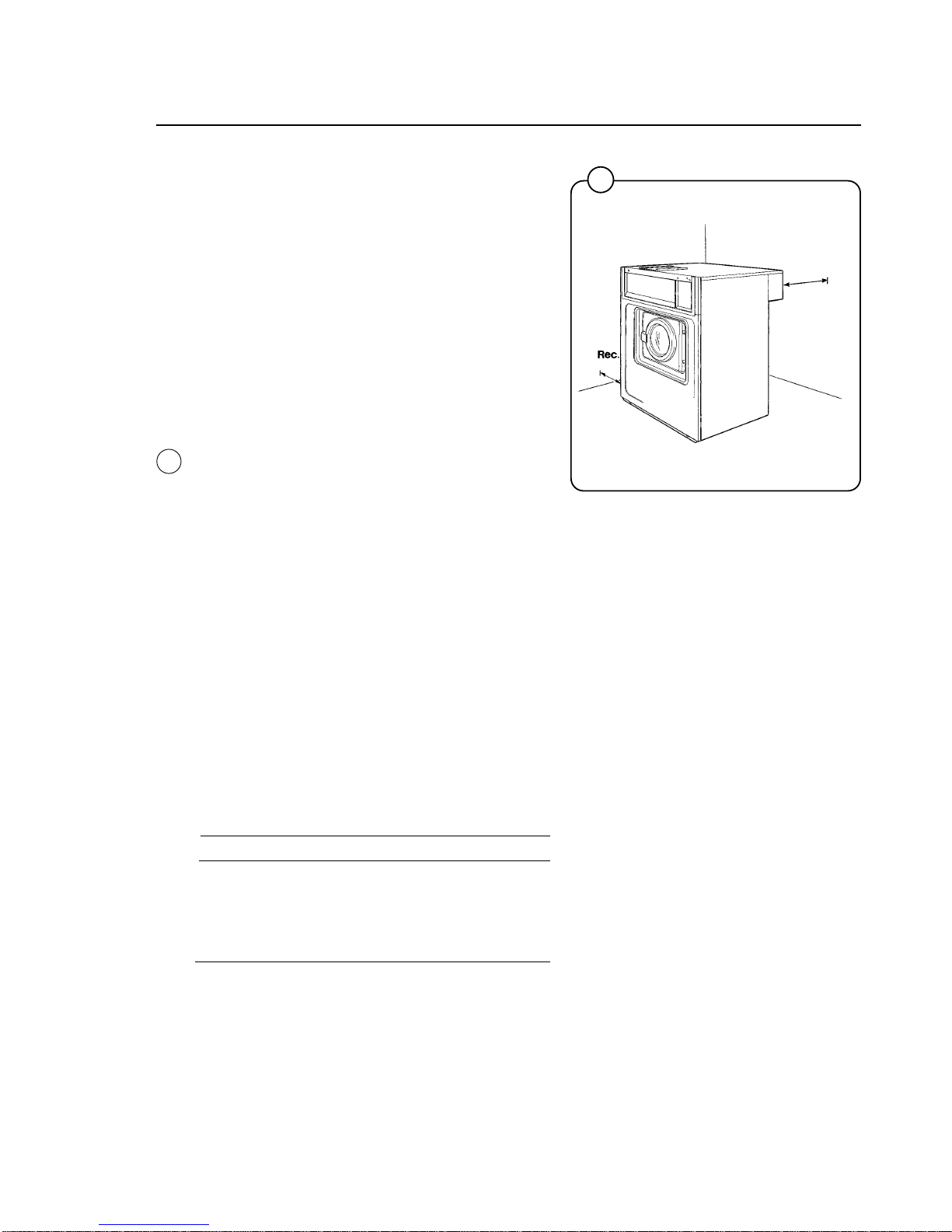
Location
Install the machine close to a floor drain or open
trough.
In order to make installation and servicing the
machine easier the following clearances are
recommended:
• At least 20" between the machine and the wall
behind
• and a minimum of 2" on both sides of the
machine whether installed next to the wall or
other machines.
Where space is limited it is possible to reduce
this distance to a minimum of 1" at the rear and
sides, since most service operations are carried
out from the front or top of the machine.
Floor
The floor must be able to withstand the following
loads:
EX-15 ES EX-25 ES
static 390 lbs 598 lbs
dynamic 170 lbs 220 lbs
frequency of 17 Hz 17 Hz
dynamic force
0243
5
20"
2"
Installation
2
Fig.
2
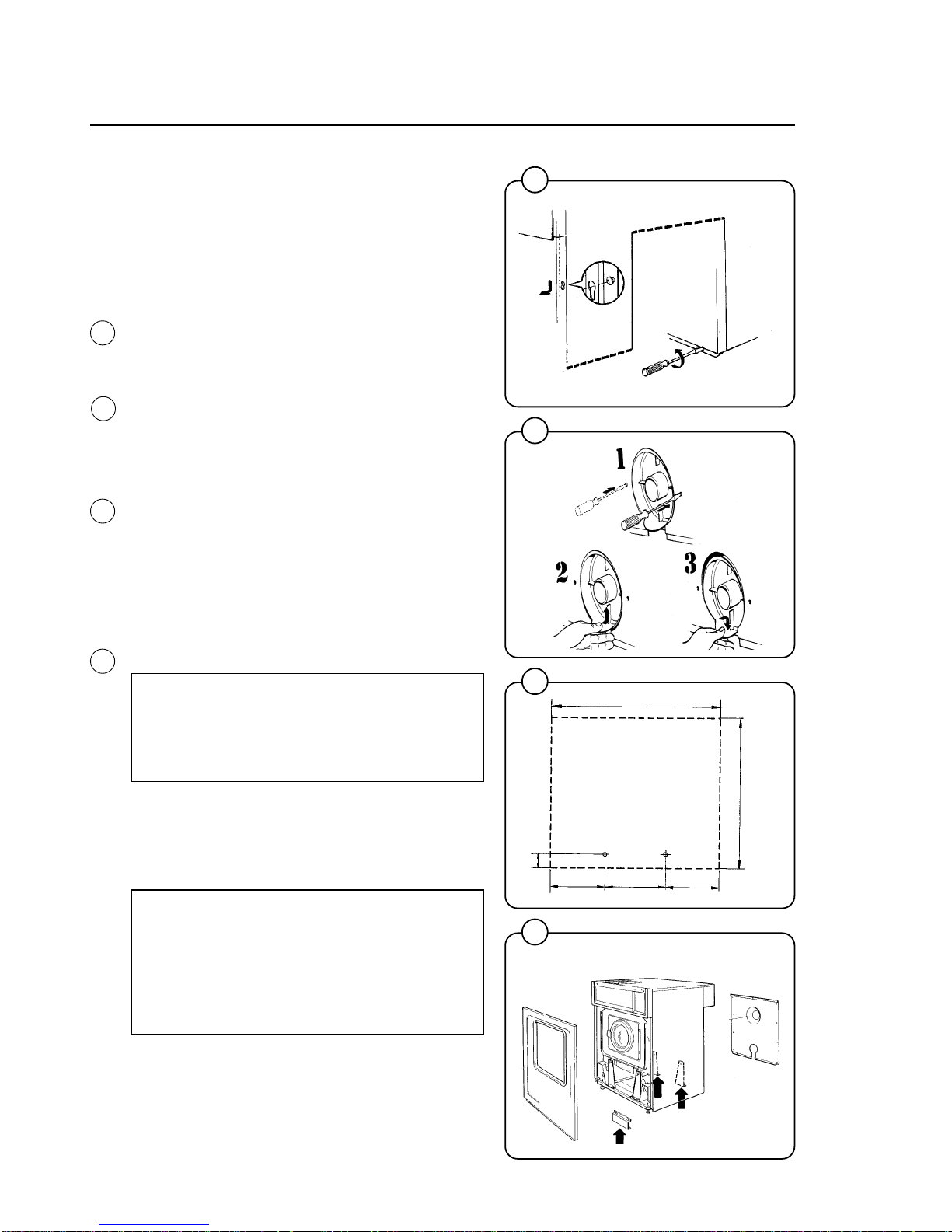
Mechanical installation
Each machine is delivered with the drum locked
in place by four security bolts fitted between the
frame and the drum. In orderto remove these
and install the machine, proceed as follows:
• Unpack the machine.
• Slacken off the screws in the lower edge of
the front cover plate and remove the plate by
pulling downward and outward to unhook it
from the chassis.
• Unscrew the retaining screws on the rear
plate and remove the plate. Remove the
drainage connection by unscrewing the two
screws. Lift the drainage connection upwards
until comes loose from the rear plate.
• Mark and drill two holes (diameter =5/16")
about 4" deep in the positions shown.
• Remove the machine from the transport pallet.
Fit the adjustable feet provided.
• Place the machine above the bolt holes you
just drilled. Always lift the machine by the
chassis, never by the door or door handle.
• Remove the four security bolts holding the
drum to the chassis.
NOTE!
These security bolts must be removed
before operating the machine or it may be
damaged.
• Check that the machine is level and steady.
Adjust the level by using the four adjustable
feet (check first that they are screwed in as far
as possible). Lock the feet using the lock nuts
when the machine is satisfactorily positioned.
NOTE!
It is of utmost importance that the
machine be level, from side- to- side as
well as front- to- rear. If the machine is not
properly leveled, it may result in a false
out-of-balance cutout.
• Insert the expansion bolts supplied in the
holes drilled in the floor.
Fit the washers and nuts, and tighten well.
After the machine has been in use for a while
check and retighten the nuts if necessary.
0674
0244
0672
0671
6
EX 7
EX 10
720 mm
65mm
230mm
260mm
230mm
2 9/16 in
9 1/16 in
10 1/4 in
9 1/16 in
28 11/32 in
EX-25:
820mm
32 9/32 in
EX-15:
660mm
26 in
Fig.
4
Installation
3
4
5
6
Fig.
5
Fig.
3
Fig.
6
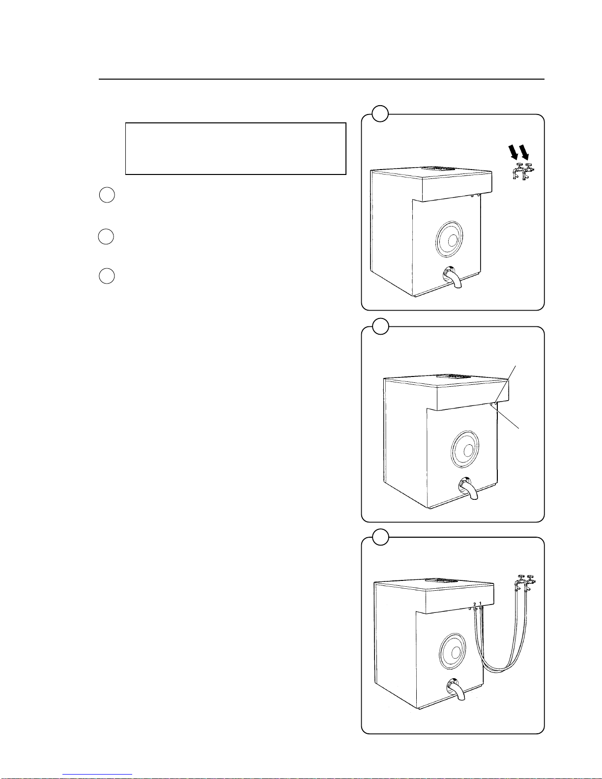
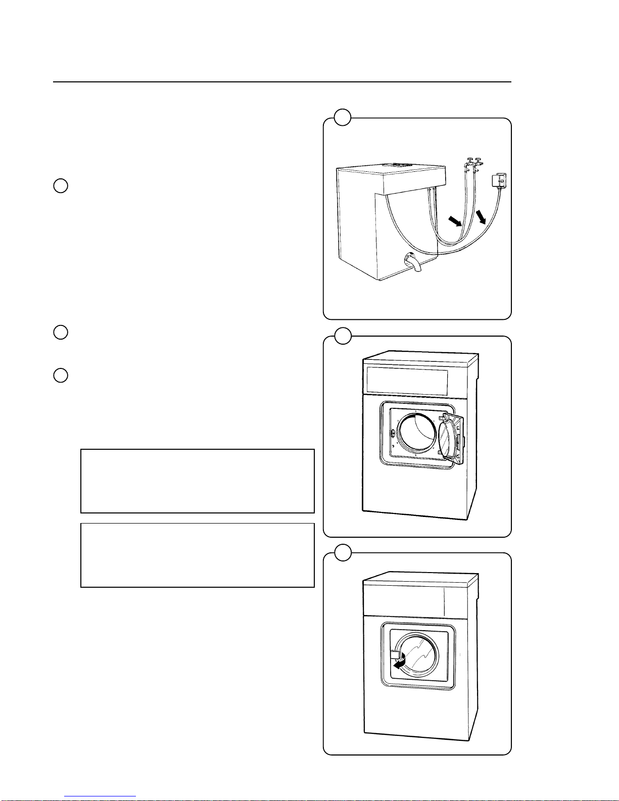
Water supply
NOTE!
All plumbing must conform to national
and local plumbing codes.
The water supply to the machine should be fitted
with manual shut-off valves to facilitate installation and servicing.
Water inlets are labelled for hot and cold water
connections. Hoses should be flushed through
before being connected to the machine.
Connection hoses should be 3/4" reinforced
rubber hosing not to exeed 6 ft in length. Make
sure the hoses have no sharp bends or angles.
Water pressure should be:
maximum: 142 psi (10 kp/cm
2
)
recommended: 25-85 psi (2-6 kp/cm
2
)
7
0248
1597
1598
Cold water
Hot water
Fig.
7
Fig.
8
Fig.
9
Installation
7
8
9
8
3147
0057
Steam connections (optional steam heating)
The steam inlet pipe must be fitted with a manual
cut-off valve in order to facilitate installation and
service operations.
Fit the filter supplied to the manual cut off valve.
The connection hose must be of an approved type.
Connection size at filter: DN 15 (1/2").
Steam pressure required:
minimum: 7.1 psi (0.5 kp/cm
2
)
maximum: 114 psi (8 kp/cm
2
)
recommended: 57 psi (4 kp/cm
2
)
Check that there are no sharp angles or bends in
the connection hose.
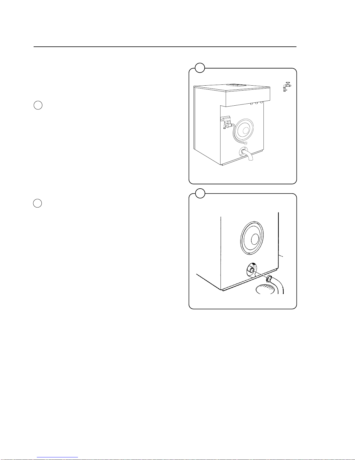
Drain connection
Connect a 50 mm (2") pipe or rubber hose to the
machine’s drain pipe. Avoid sharp bends which
may prevent proper draining.
The drainage pipe should be located over a floor
drain, drainage channel or similar so that the
distance between the outlet and the drain is at
least 25 mm (1"). Refer to local regulations on
watersupply and drainage.
Installation
10
11
Fig.
10
Fig.
11
9
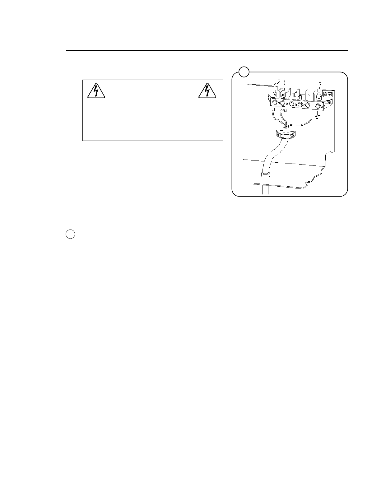
Electrical installation
Electrical installation must be carried out
by an authorized electrician, and must
follow national and local regulations. Make
sure that the ground wire is properly
connected.
• Install a 1-phase circuit breaker for the
machine’s electrical supply.
• Connect the machine’s cable between the
circuit breaker and the machine.
• Check that the earth ground has been
connected in the correct way.
For the rating of the supply cable, check the local
regulations.
Machines connected for 1-phase 120V or 240V
AC.
Installation
12
3150 b
Fig.
12
10
13
15
1600
1602
1820
Start-up and safety checklist
Before initial start-up of a Wascomat washerextractor, the following safety checks must be
performed:
• Make sure that all electrical and plumbing
connections have been made in accordance
with applicable local codes.
• Use only flexible water fill and drain hoses of
the proper length to avoid sags and kinks.
• Make sure the machine is properly grounded
electrically.
Before the machine is operated, the door safety
interlock must be checked for proper operation
as follows:
• When washer loading door is open, the
machine must not start. Verify this by
attempting to start washer with door open.
• When washer is in operation, the loading door
is locked and cannot be opened. Verify this by
attempting to open the loading door when the
machine is operating. If necessary, consult
this manual for proper operation of the door
lock and door safety interlock or call a
qualified serviceman.
IMPORTANT:
Door safety interlock must be checked daily
in accordance with above procedure.
WARNING:
Before servicing Wascomat equipment,
disconnect electrical power.
Installation
Fig.
13
14
Fig.
14
Fig.
15
11
1822
16
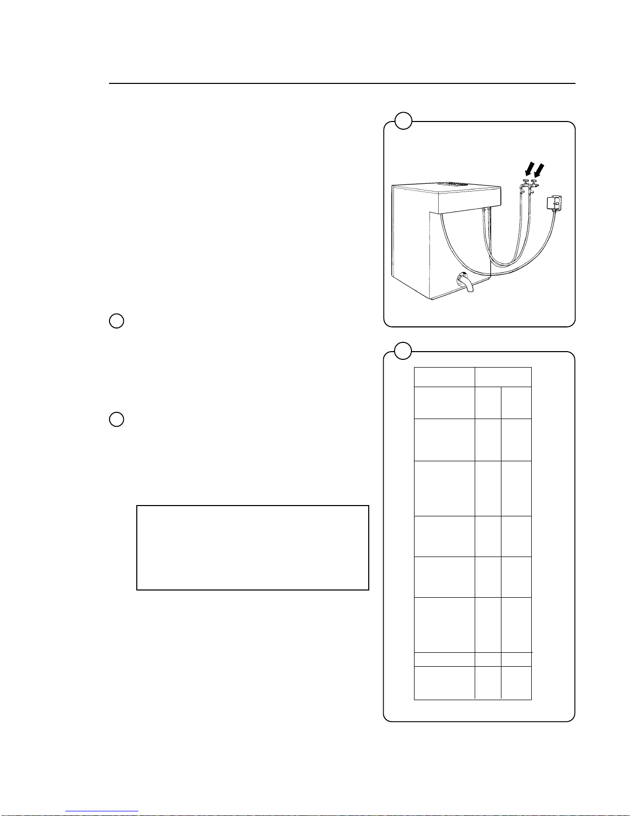
Function control check-out list
In the machine cylinder, you will find the warranty
registration card, a copy of the warranty policy
and other pertinent material.
The warranty card should be completed and sent
to Wascomat. All other items should be placed in
a safe place for future reference.
The machine should be cleaned when the
installation is completed and checked out as
detailed below without loading the machine with
fabrics:
1. Check the incoming power for proper voltage,
phase and cycles.
2. Open manual shut-off valves to the machine.
3. Turn on electric power.
4. Check the door safety interlock as detailed on
page 10 of this manual.
5. Select the HOT program and start the
machine.
6. Run through a complete cycle, checking for
water temperature, drain operation and the
extract function.
7. In the mainwash only hot water should enter.
If cold water comes in, the hoses are
improperly connected. Reverse hot and cold
water hoses.
NOTE
All machines are factory tested prior to
shipment. Occasionally, some residual
water may be found when the machine is
installed.
17
HOT
Time Temp.
(Min.)
Prewash 3 Warm
Detergent 1
Drain 1
Mainwash 6 Hot
Detergent 2
Drain 0.7
Extraction 0.5
Rinse 1 1 Warm
Drain 0.7
Extraction 0.5
Rinse 2 1 Cold
Drain 0.7
Extraction 0.5
Rinse 3 2 Cold
Detergent 3
Drain 0.7
Extraction 4
Shake-out 0.5
Total time 22
(water fill time
not included)
1203
Fig.
17
Fig.
16
Installation

12
Safety rules
• This machine is designed for water washing only.
• Machines must not be used by children.
• All installation operations are to be carried out by qualified personnel.
Licensed personnel are necessary for all electric power wiring.
• The interlock of the door must be checked daily for proper operation
and must not be bypassed.
• All seepage in the system, due to faulty gaskets etc., must be repaired
immediately.
• All service personnel must be fully familiar with the operating manual
before attempting any repair or maintenance of the machine.
• This machine must not be sprayed with water, otherwise short circuiting
may occur.
• Fabric softeners with volatile or inflammable fluids are not to be used in
this machine.
Safety Rules
13
7
Heavy Soil Prewash
Prewash
Wash
Rinses
Final Extract
Extra Extract
Doorlock delay
Door unlocked
Add bleach if desired
Rinse 1
Rinse 2
Rinse 3Softener
EXTRA
EXTRACT
GENTLE
WASH
A
B
2
3
4
5
START
Hot
Warm
Cold
Delicate
Perm Press
Quick-Wash
Heavy Soil
6
1
1
1
2
3
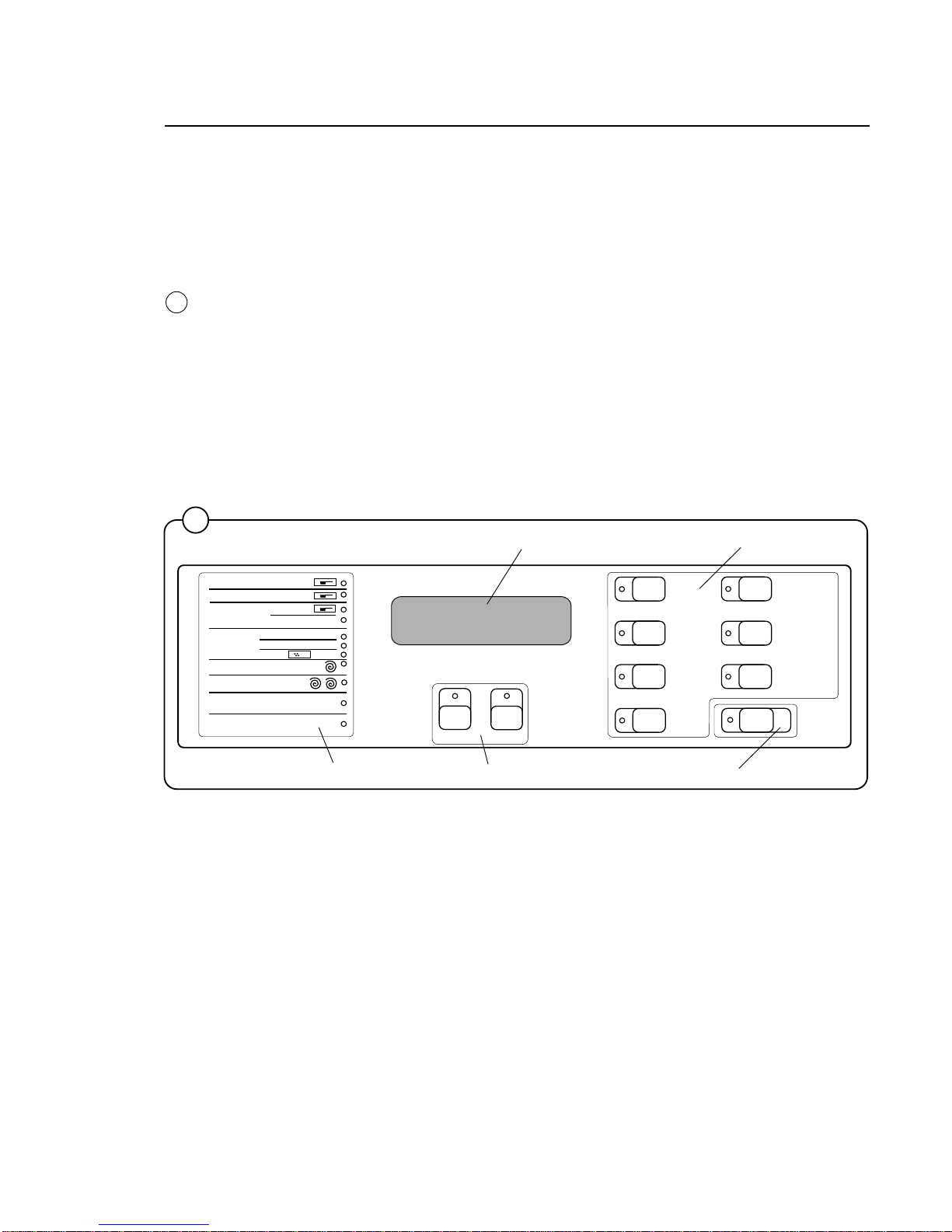
The Emerald Series program unit controls the various functions of the machine
in a certain time sequence with the aid of seven built-in standard programs.
The standard programs can also be modified by selecting various options. By
selecting options, the user has access to programs for all types of wash loads
and degrees of soiling.
The control panel consists of program selection buttons (A), option buttons (B),
a combined start, pause and rapid advance button (C), symbols with LEDs (D)
which show the program selected and the program sequence, plus an alphanumeric display (E).
The alphanumeric display shows illuminated green characters.
In the event of faults, error codes will be displayed on this window. See Fault
codes.
18
Explanation of control panel
A Program selection buttons
B Option buttons
C Start/pause and rapid advance button
D Symbols with LEDs to indicate program sequence
E Information display
3423
Fig.
18
Operating instructions
D
E
B
A
C
14
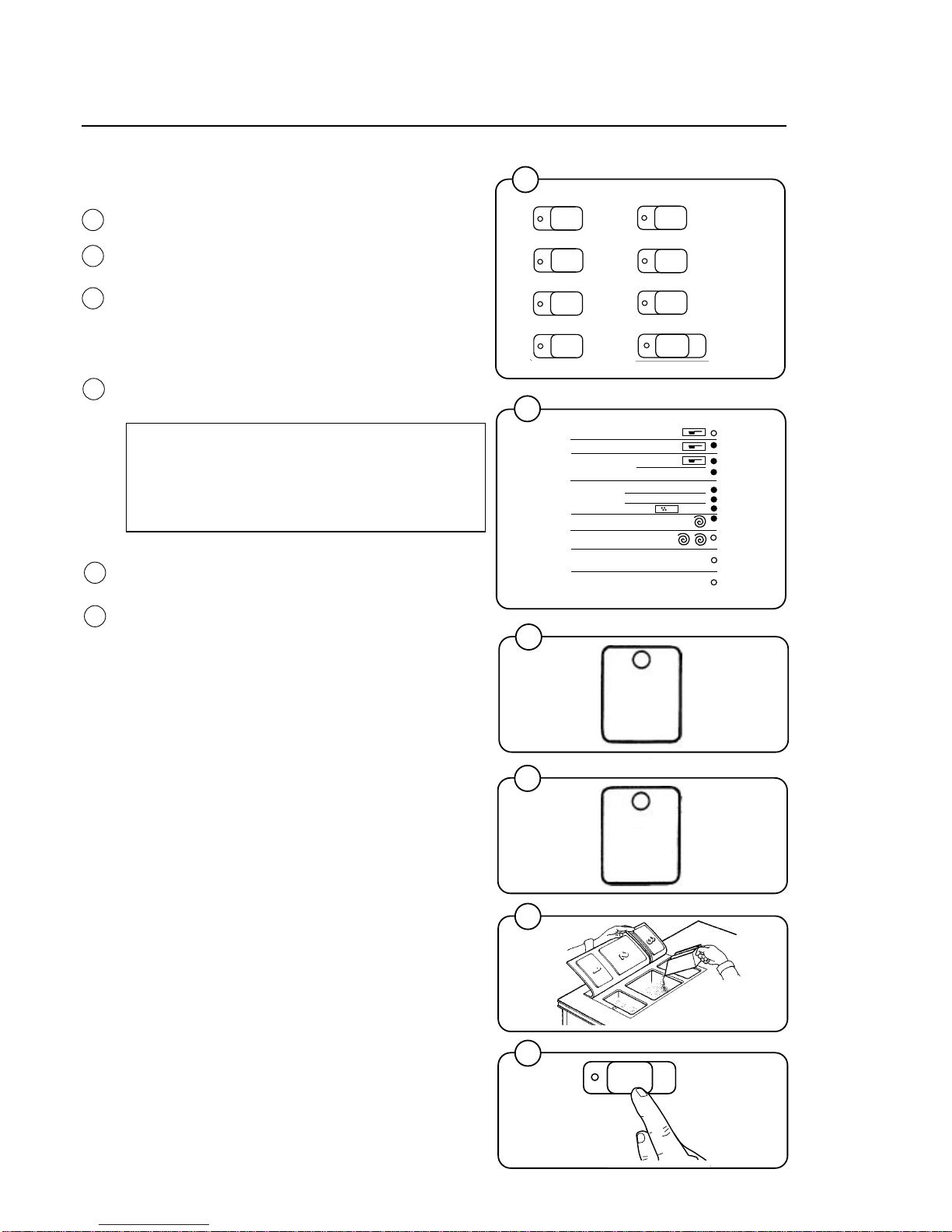
Washing
• Press the button for the desired program.
• Now the LEDs alongside the program symbols
will show what the selected program consists of.
• Press the button(s) for any options required.
• This option button gives a longer extraction time
on "Hot", "Warm", "Cold", "Delicate" and "Perm
Press" programs.
• This option button gives "Gentle action" in all
programs except "Delicate" which has gentle
action as standard.
NOTE!
Gentle actions consists of 6 seconds pause,
as opposed to 18 seconds rotation and 6
seconds pause for Normal action.
• Add the correct amount of detergent and fabric
softener.
• Press the START button.
3426
2288
2289
2290
3427
3435
23
22
21
20
Fig.
19
Fig.
20
Fig.
22
A
B
Operating Instructions
19
24
Fig.
21
Perm Pres
s
Quick-Was
h
2
3
4
5
START
Hot
Warm
Cold
Delicate
Heavy Soil
6
1
7
Heavy Soil Prewash
Prewash
Wash
Rinses
Final Extract
Extra Extract
Doorlock delay
Door unlocked
Add bleach if desired
Rinse 1
Rinse 2
Rinse 3Softener
1
1
2
3
START
Fig.
23
Fig.
24
15
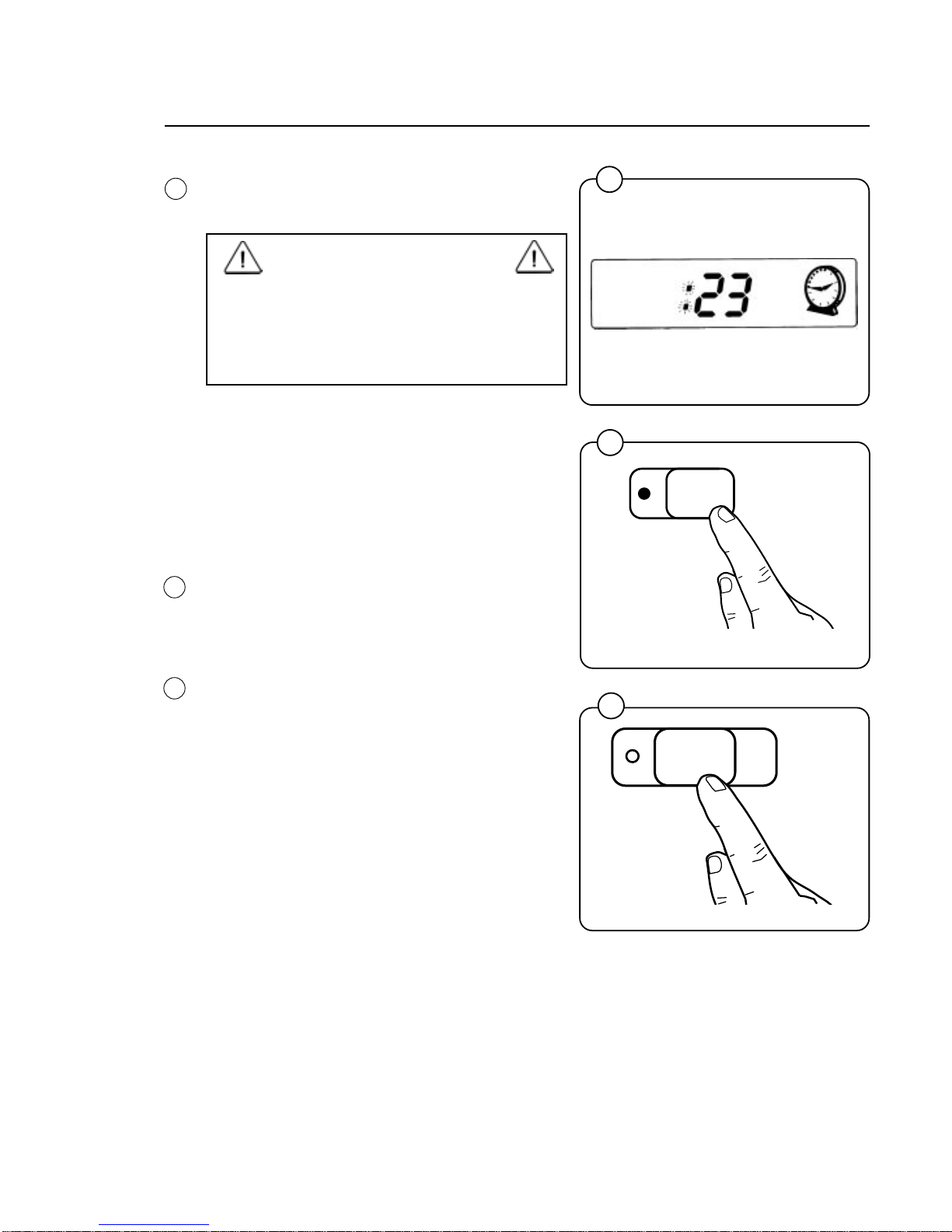
• Now the display will show the clock symbol
and two digits. The two digits are the time
left before the wash will be finished.
The two digits indicating time left will not
appear when the machine is first installed.
Each program needs to have been used at
least once before the time left will be
displayed.
• For 5 minutes immediately after START is
pressed the colon character (
: ) will flash on
the display. As long as this character is still
flashing a new program can be selected
(without the drain opening). This means you
still have the chance to change the setting if
the wrong program has been selected. Do
as follows:
• Press START.
• Select a new program.
• Press START again after making any
change in the program selected.
If for any reason you wish to halt the wash
cycle for a time, press the START button for a
moment or two. The program will be suspended
and the drain will remain closed.
To restart the program, press the START
button again briefly.
Fig.
25
Operating Instructions
Fig.
26
Fig.
27
27
3435
START
3434
26
Hot
1
3141
25
16
START
Operating Instructions
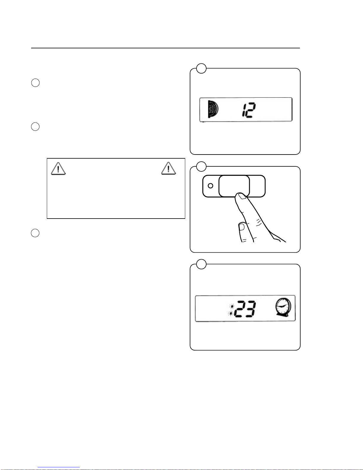
For coin-operated machines
Select a wash program, then insert the number
of coins corresponding to the figure shown on
the display.
As each coin is added the machine counts
backwards towards 00 on the display. The
machine will not start until the display shows 00.
• Press the START button.
• Now the display will show the clock symbol
and two digits. The two digits are the time left
before the wash will be finished.
The two digits indicating time left will not
appear when the machine is first installed.
Each program needs to have been used at
least once before the time left will be displayed.
• For a time immediately after START is pressed the colon character (
: ) will flash on the
display. As long as this character is still
flashing a new program can be selected
(without losing anything). This means you still
have the chance to change the setting if the
wrong program has been selected.
• Press PAUSE/START.
• Select a new program.
• If the new program costs more to run than
the amount already paid, the difference will
be shown on the display. Insert enough coins
to make the display show 00 again.
• Press START again after making any change
in the program selected.
3435
2253
Fig.
28
3141
28
29
30
Fig.
29
Fig.
30
17
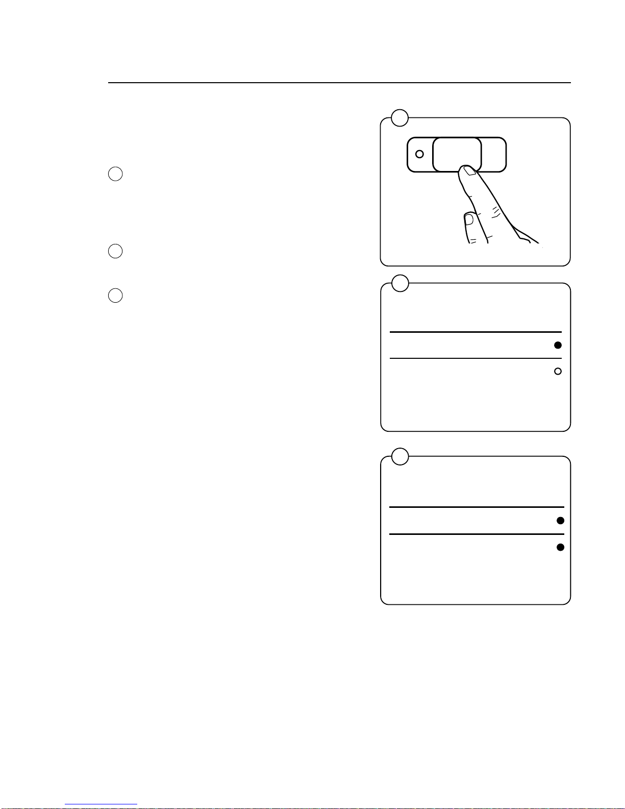
Rapid advance
Whole steps in programs can be skipped
using rapid advance.
• Press and hold the START button until
the program indicator LEDs have moved past the program steps you wish to
skip.
Program end
After final extraction, the LED by the
"doorlock delay" comes on. This shows
that the door lock will shortly be unlocked.
The door will not actually be unlocked until
the green LED by the "door unlocked"
comes on, accompanied by an audible
signal. This takes about 1 minute.
Troubleshooting
If the machine won’t start, check that:
• the circuit breaker is on.
• the manual shut-off valves for water are
open.
• a program has been selected.
• the door is properly locked.
3435
Fig.
31
3424
3425
Fig.
33
Operating Instructions
31
32
33
Fig.
32
START
Doorlock delay
Door unlocked
D
oorlock delay
D
oor unlocked

18
Operating Instructions
Maintenance
This machine has been carefully designed to minimize preventive
maintenance. However, the following routine operations should be
performed at regular intervals (depending on how much the machine is
used).
Daily
• Clean detergent residue from the door seal and check that the door
does not leak.
• Clean the detergent compartments and wipe down the machine with a
damp cloth.
• Check that the drain valve does not leak.
• Start the machine and check that the door is locked while the machine
is operating.
Every three months
• Check for leaks in valves, hoses and connections.
• Remove any lint from the machine’s drainage system.
• Check water inlet screens for clogging.
19
Programming
Coin-operated machines
In coin-operated machines the prices for the
various programs have to be programmed in.
Values from the coin mechanism (the
accumulated value) can be read out with the aid
of the service program.
If a machine is fitted with a coin mechanism after
its original installation the relevant electronic
circuitry will have to be activated before the prices
can be programmed in.
Only trained service personnel may use the
service program and program in prices for
coin operation.
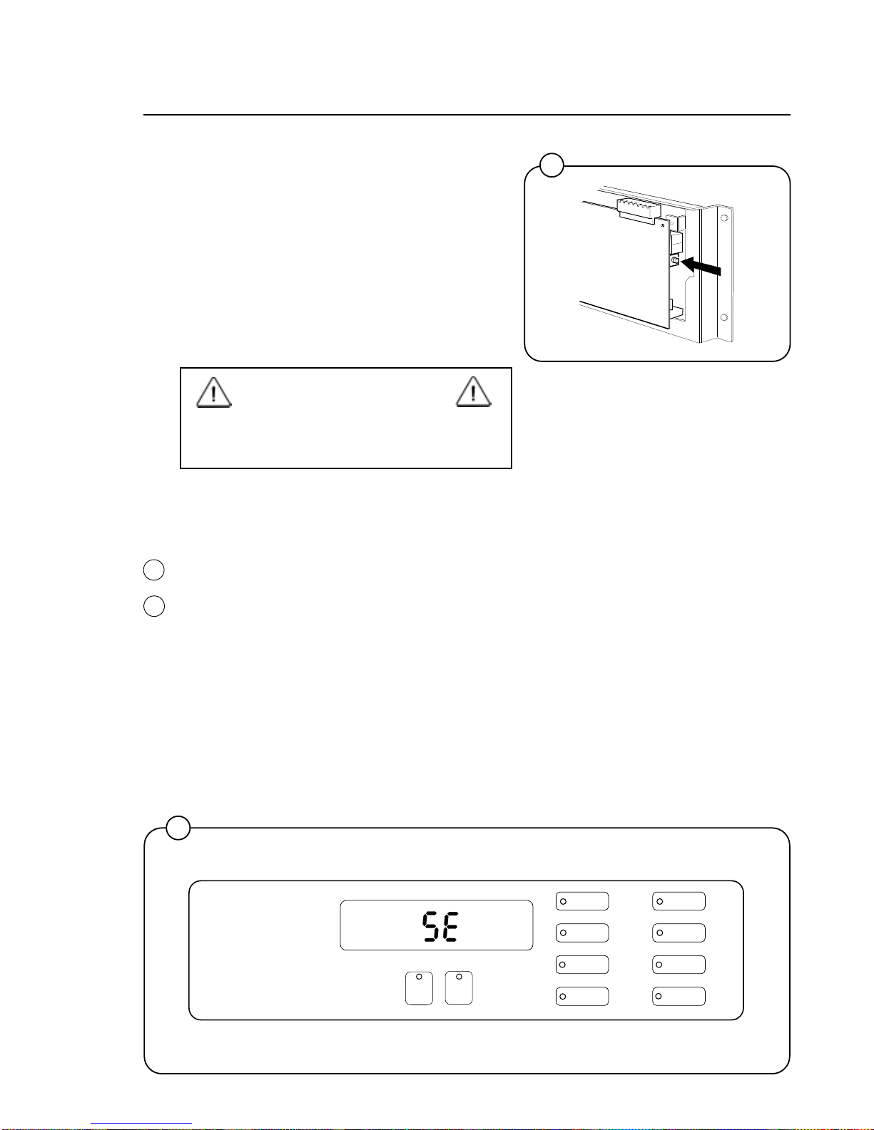
Activation of electronic circuitry in machines
fitted with coin operation after original installation.
• Press the service button.
Now certain of the buttons switch to being
number keys (1 to 9), with the START button
being 0.
3429
Fig.
34
Fig.
35
35
A
1
1
4
3
2
6
5
8
7
9
3400
34
0
20
Programming
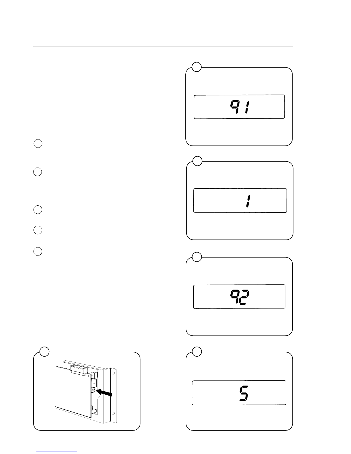
Codes 91 and 92 are used to store the values for
coin slots 1 and 2. For mechanisms with only one
slot, only code 91 is used.
The values to be stored are the ratio of one coin
to the other.
For example: if the coin slots are for a 10 cent
coin and a 50 cent coin. The value 10 should be
stored under code 91, and the value 50 should be
stored under code 92.
• Enter code 91 using the buttons which have
become number keys 9 and 1.
The display will now show 91.
• When entering the actual value: keep the
price-programming button activated (the switch
is located under the top cover at the right front
edge). Enter the value 1 and then release the
button.
• Enter code 92. The display will now show 92.
• Enter the value 5.
• Exit the service program by pressing the
service button again.
2275
2274
2276
2272
3400
36
37
38
3940
Fig.
36
Fig.
37
Fig.
38
Fig.
39
Fig.
40
21
Programming
Price programming:
• Press the relevant wash program selector
button.
When programming the price of a wash program
plus options, press both the relevant program
selector button and the option button.
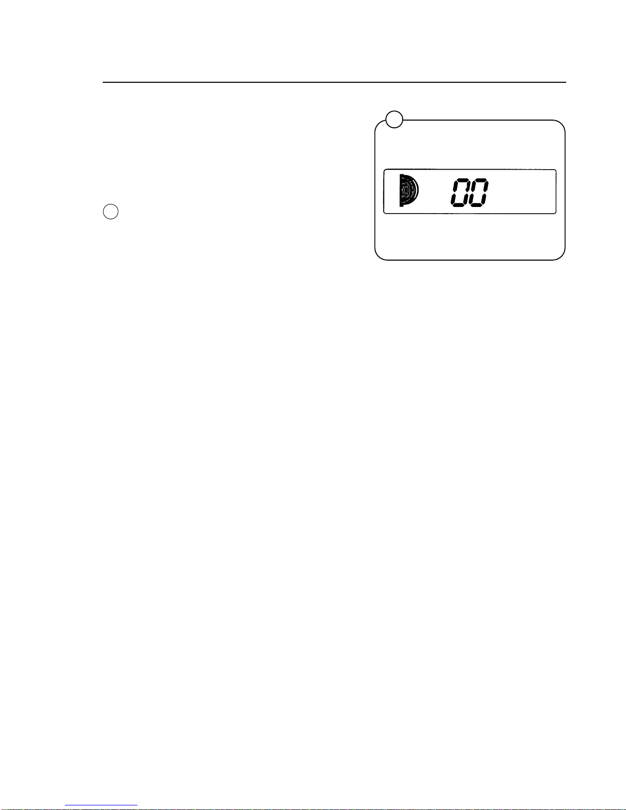
• Keep the price-programming button activated.
Now the display shows 00 plus the coin sym-
bol.
• Enter the price via the numerical key functions.
The START button can be used to enter 0.
• Release the price-programming button.
This procedure should be repeated for all wash
programs.
2273
41
Fig.
41
22
Wash Cycles
In the figure below and on the following page is an overview of the seven
wash cycles.
On the pages following you will find a more detailed description of the
cycles.
42
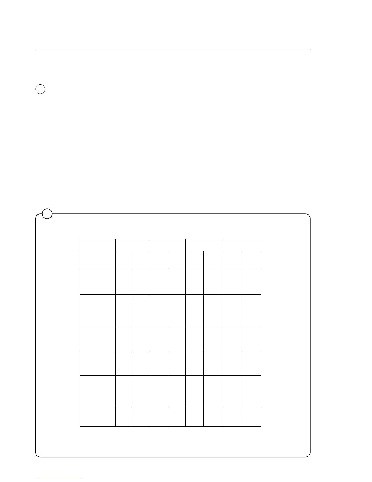
HOT WARM COLD PERM PRESS
Time Temp. Time Temp. Time Temp. Time Temp.
(Min.) (Min.) (Min.) (Min.)
Prewash 3 Warm 3 Warm 3 Cold 3 Warm
Detergent 1
Drain 1 1 1 1
Mainwash 6 Hot 6 Warm 6 Cold 6 Warm
Detergent 2
Drain 0.7 0.7 0.7 0.7
Extraction 0.5 0.5 0.5 0.5
Rinse 1 1 Warm 1 Cold 1 Cold 1 Cold
Drain 0.7 0.7 0.7 0.7
Extraction 0.5 0.5 0.5 0.5
Rinse 2 1 Cold 1 Cold 1 Cold 1 Cold
Drain 0.7 0.7 0.7 0.7
Extraction 0.5 0.5 0.5 0.5
Rinse 3 2 Cold 2 Cold 2 Cold 2 Cold
Detergent 3
Drain 0.7 0.7 0.7 0.7
Extraction 4 4 4 2
Total time 22 22 22 20
(water fill time
not included)
Wash Cycles
Fig.
42
23
43
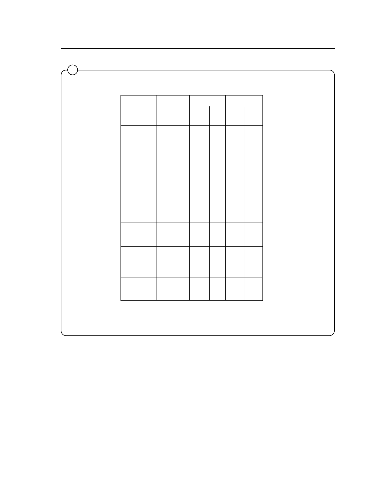
DELICATE QUICK-WASH HEAVY SOIL
Time Temp. Time Temp. Time Temp.
(Min.) (Min.) (Min.)
Prewash 2 Warm
Drain 1
Prewash 3 Warm
Detergent 1
Drain 1
Mainwash 4 Warm 5 Warm 8 Hot
Detergent 2
Drain 0.7 0.7 0.7
Extraction 0.5 0.5 0.5
Rinse 1 1 Cold 1 Cold 1 Warm
Drain 1 1 0.7
Extraction 0.5
Rinse 2 1 Cold 1 Cold 1 Cold
Drain 1 1 0.7
Extraction 0.5
Rinse 3 2 Cold 2 Cold 2 Cold
Detergent 3
Drain 0.8 0.8 0.8
Extraction 1 4 4
Total time 13 17 27.4
(water fill time
not included)
Wash Cycles
 Loading...