

Page 1

Published Manual Number/ECN: MAT30C4AAE/2002115N
• Publishing System: TPAS
• Access date: 03/14/2002
• Document ECN's: Latest Available
Technical Reference—
Operating and
Troubleshooting the C4A
Electronic Coin WasherExtractor
PELLERIN MILNOR CORPORATION POST OFFICE BOX 400, KENNER, LOUISIANA 70063-0400, U.S.A.
Page 2

Please Read
About the Manual Identifying Information on the Cover
The front cover displays pertinent identifying information for this manual. Most important, are
the published manual number (part number) /ECN (date code). Generally, when a replacement
manual is furnished, it will have the same published manual number, but the latest available ECN.
This provides the user with the latest information applicable to his machine. Similarly all
documents comprising the manual will be the latest available as of the date the manual was
printed, even though older ECN dates for those documents may be listed in the table of
contents.
When communicating with the Milnor factory regarding this manual, please also provide the
other identifying information shown on the cover, including the publishing system, access date,
and whether the document ECN’s are the latest available or exact.
References to Yellow Troubleshooting Pages
This manual may contain references to “yellow pages.” Although the pages containing
troubleshooting procedures are no longer printed on yellow paper, troubleshooting instructions, if
any, will be contained in the easily located “Troubleshooting” chapter or section. See the table of
contents.
Trademarks of Pellerin Milnor Corporation
The following, some of which may be used in this manual, are trademarks of Pellerin Milnor
Corporation:
®
Ampsaver
Autolint
®
Auto-Purge
Autovac E-P OneTouch® Mildata
®
CBW
Dye-Extractor® Gear Guardian
Dyextractor® Hands-Off
®
E-P Express® Hydro-Cushion
E-P Plus
®
®
®
®
®
®
Milnet
Milnor
®
Staph-Guard
System 4
Miltrac System 7
Miltron Totaltrol
®
®
®
®
Comments and Suggestions
Help us to improve this manual by sending your comments to:
Pellerin Milnor Corporation
Attn: Technical Publications
P. O. Box 400
Kenner, LA 70063-0400
Fax: (504) 469-1849
Page 3

Table of Contents
for MAT30C4AAE/2002115N
Operating and Troubleshooting the C4A Electronic Coin Washer-Extractor
Page Description Document/ECN
1 About This Manual MHT30C4AAE/9274AV
2 Safety for Coin Operated Washer-Extractors BIRMCS01/20020312
9 Section 1: Commissioning
10 The C4A Electronic Coin Washer-Extractor Control MSOP0503AE/9274AV
11 Section 2: Operating
12 Operation of C4A Electronic Coin Washer-Extractor MSOP0502AE/9274AV
15 How to Set Required Number of Coins MSIN0501AE/9274AV
17 Section 3: Troubleshooting
18 Testing Display, Inputs, and Outputs on the Electronic
Coin Washer-Extractor MSTS0501AE/9274AV
23 How to Correct Errors with the C4A Control MSTS0502AE/9274AV
25 Section 4: Supplemental Information
26 The Hardware in C4A Electronic Coin Washer-
Extractor Controls MSFD0503AE/9274AV
28 How to Change EPROMS in Microprocessors
and Where to Check the DC Voltages MSSM0217AE/9020IV
Page 4

Page 5

MHT30C4AAE/9274AV (1 of 1)
ABOUT THIS MANUAL
ËScope—This instruction manual is intended to provide operating and troubleshooting instructions for the
C4A electronic coin washer-extractor control. Refer to the INSTALLATION AND SERVICE manual for
information on machine installation procedures, mechanical requirements, preventive maintenance, service
procedures, and mechanical parts identification. Refer to the SCHEMATIC MANUAL for electrical parts
identification and electrical troubleshooting.
ËThe Power Up Sequence—Verify that the machine behaves as described in “OPERATION OF
C4A . . . ” (see Table of Contents). Any other display indicates an error condition which must be corrected
before the machine will operate. See “HOW TO CORRECT ERRORS WITH THE C4A CONTROL.”
ËQuick Reference Tabs—The tabs along the right edge of the manual mark vital information.
SAFETY—READ FIRST—Safety instructions must be read before operating machine.
COMMISSIONING—Commissioning instructions ensure proper start up.
CONTENTS—See Table of Contents for section/page numbers of cross references used herein.
CHANGES/NEW MATERIALS—These, if any, will be found in an envelope inside the rear
cover.
ËManual Number/Date Code (When To Discard or Save)—The manual number/date
code is located on the inside front cover, upper right corner just above the manual name. Whenever the
manual is reprinted with new information, part of this number changes. If the date code after the “/”
changes, the new version applies to all machines covered by the old version, but is improved— thus
the old version can be discarded. If the manual number before the “/” changes, the new manual covers
only n ew machines. Example: Discard MATMODELAE/8739CV when MATMODE LAE/8739DV is
received (minor improvements). Also, discard MATMODELAE/8739DV when MAT-
MODELAE/8746AV is received (major improvements). But keep MATMODELAE/8746FV when MAT-
MODELBE/8815AV is received, since the new manual no longer applies to machines originally shipped
with the old manual.
ËDocuments and Change Bars—The individual documents comprising this manual use the same
revisio n criteria as the manual. Text documents als o display change bars. Example: When section
MSOP0599AE/9135BV becomes MSOP0599AE/9135CV, change bars with the letter “C” appear next to
all changes for this revision. For a major rewrite (e.g., MSOP0599AE/9226AV), all change bars are deleted.
ËTrademarks of Pellerin Milnor Corporation—The following, some of which may be used in
this publication, are trademarks of Pellerin Milnor Corporation:
Ampsaver
®
Autolint
®
Auto-Purge
®
Autovac
CBW
®
Dye-Extractor
®
Dyextractor
®
E-P Plus
®
Gear Guardian
®
Hands-Off
®
Hydro-Cushion
®
Mildata
®
Milnet
®
Milnor
®
Miltrac
Miltron
Staph-Guard
®
System 4
®
System 7
®
Totaltrol
®
Page 6

CQVUdi V_b 3_Y^ ?`UbQdUT GQcXUb5hdbQSd_bc
29B=3C ! @eR\YcXUT 2__[ c`USc 4QdUc* " " #!" " " #!" " " #!" <Q^W* 5>7 ! 1``\YS* B=3
BPUTchU^a2^X]>_TaPcTSFPbWTa4gcaPRc^ab
6T]TaP[BPUTchAT`dXaT\T]cbb_TRXUXRfPa]X]Vb]Tgc_PVTP]S
cWa^dVW^dc\P]dP[
Incorrect installation, neglected preventive maintenance, abuse, and/or improper repairs, or
changes to the machine can cause unsafe operation and personal injuries, such as multiple
fractures, amputations, or death. The owner or his selected representative (owner/user) is
responsible for understanding and ensuring the proper operation and maintenance of the machine.
The owner/user must familiarize himself with the contents of all machine instruction manuals.
The owner/user should direct any questions about these instructions to a Milnor® dealer or the
Milnor® Service department.
Most regulatory authorities (including OSHA in the USA and CE in Europe) hold the owner/user
ultimately responsible for maintaining a safe working environment. Therefore, the owner/user
must do or ensure the following:
• recognize all foreseeable safety hazards within his facility and take actions to protect his
personnel, equipment, and facility;
• work equipment is suitable, properly adapted, can be used without risks to health or safety,
and is adequately maintained;
• personnel are familiar with all functional and safety aspects of the machine, and where
specific hazards are likely to be inv olv ed, access to the equipment is restricted to those
employees given the task of using it;
• only specifically designated workers carry out repairs, modifications, maintenance, or
servicing;
• info rm ation, ins tru ction, and tra in ing is provided ;
• workers and/or their representatives are consulted.
Work equipment must comply with the requirements listed below. The owner/user must verify
that installation and maintenance of equipment is performed in such a way as to support these
requirements:
• control devices must be visible, identifiable, and marked; be located outside dangerous zones;
and not give rise to a hazard due to unintentional operation;
• control systems must be safe and breakdown/damage must not result in danger;
• work equipment is to be stabilized;
• protection against rupture or disintegration of work equipment;
• guarding, to prevent access to danger zones or to stop movements of dangerous parts before
the danger zones are reached. Guards to be robust; not give rise to any additional hazards; not
be easily removed or rendered inoperative; situated at a sufficient distance from the danger
zone; not restrict view of operating cycle; allow fitting, replacing, or maintenance by
restricting access to relevant area and without removal of guard/protection device;
• suitable lighting for working and maintenance areas;
• maintenance to be possible when work equipment is shut down. If not possible, then
protection measures to be carried out outside danger zones;
• work equipment must be appropriate for preventing the risk of fire or overheating; discharges
of gas, dust, liquid, vapor, other substances; explosion of the equipment or substances in it.
@5<<5B9> =9<>?B 3?B@?B1D9?>
Page 7

CQVUdi V_b 3_Y^ ?`UbQdUT GQcXUb5hdbQSd_bc
;Pd]Sah5PRX[Xch
—Provide a supporting floor that is strong and rigid enough to support–with
a reasonable safety factor and without undue or objectionable deflection–the weight of the fully
loaded machine and the forces transmitted by it during operation. Provide sufficient clearance for
machine movement. Provide any safety guards, fences, restraints, devices, and verbal and/or
posted restrictions necessary to prevent personnel, machines, or other moving machinery from
accessing the machine or its path. Provide adequate ventilation to carry away heat and vapors.
Ensure service connections to installed machines meet local and national safety standards,
especially regarding the electrical disconnect (see the National Electric Code). Prominently post
safety information, including signs showing the source of electrical disconnect.
!
?Tab^]]T[
—Train personnel what to do in case of emergencies. Inform personnel about
hazard avoidance and the importance of care and common sense. Provide personnel with the
safety and operating instructions that apply to them. Verify that personnel use proper safety and
operating procedures. Verify that personnel understand and abide by the warnings on the
machine and precautions in the instruction manuals.
"
BPUTch3TeXRTb
—Ensure that no one eliminates or disables any safety device on the machine
or in the facility. Do not allow machine to be used with any missing guard, cover, panel or door.
Service any failing or malfunctioning device before operating the machine.
#
<PX]cT]P]RT
—Ensure the machine is inspected and serviced in accordance with the norms of
good practice and with the preventive maintenance schedule. Replace belts, pulleys, brake
shoes/disks, clutch plates/tires, rollers, seals, alignment guides, etc. before they are severely
worn. Immediately investigate any evidence of impending failure and make needed repairs (e.g.,
cylinder, shell, or frame cracks; drive components such as motors, gear boxes, bearings, etc.,
whining, grinding, smoking, or becoming abnormally hot; bending or cracking of cylinder, shell,
frame, etc.; leaking seals, hoses, valves, etc.) Do not permit service or maintenance by
unqualified personnel.
!
CWT3P]VTa5a^\PA^cPcX]V2h[X]STa
A tremendous amount of potential energy is stored in the rotating cylinder of any washerextractor (even at slow speed). Washer-extractors are equipped with a
door interlock
designed to
prevent the door from being opened if the cylinder is turning and to prevent the machine from
starting unless the door is closed and locked.
Some coin machine models permit the door to be opened only during the first few minutes of the
formula and only while the machine is rotating in wash speed. If the door is opened, the drain
valve opens immediately, the machine stops, and (provided the machine still has electric power),
on most models a brake is immediately applied.
30=64A ) 4]cP]V[T P]S BTeTa 7PiPaSb
—Contact with goods being processed can
cause the goods to wrap around your body or limbs and dismember you. The goods are normally
isolated by the locked cylinder door.
• Do not put any part of your body in the machine while it is moving.
• Do not operate the machine with the door open.
• Do not attempt to open the door or reach into the cylinder until the cylinder is stopped.
• Do not touch goods inside or hanging partially outside the turning cylinder.
• Do not open the cylinder door with water in the cylinder.
• Do not tamper with or disable any safety device or operate the machine with a
malfunctioning safety device. Request authorized service.
@5<<5B9> =9<>?B 3?B@?B1D9?>
Page 8

CQVUdi V_b 3_Y^ ?`UbQdUT GQcXUb5hdbQSd_bc
• Do not operate the machine with a malfunctioning door interlock.
30=64A ! ) 4g_[^bX^] 7PiPaSb
—Cylinder—A damaged cylinder can rip apart during
extraction, puncturing the shell and discharging metal fragments at high speed.
• Do not operate the machine with any evidence of damage or malfunction.
"
CWT3P]VTa5a^\?a^RTbbX]VFXcW5[P\\PQ[T<PcTaXP[b
Washer-extractors are manufactured specifically for use with water,
nor with any other material that might be fla mm able
. They are not suitable for any type of
not with any type solvent
solvent cleaning process.
30=64A " ) 4g_[^bX^] P]S 5XaT 7PiPaSb
—Flammable substances can explode or ignite
in the cylinder, drain trough, or sewer. The machine is designed for washing with water, not any
other solvent. Processing can cause solvent-containing goods to give off flammable vapors.
• Do not use flammable solvents in processing.
• Do not load machine with goods containing dry cleaning materials.
• Do not use the machine in the presence of solvent fumes.
#
CWT3P]VTa5a^\>_TaPcX]VFXcW6dPaSb^a2^eTabAT\^eTS
Like other types of industrial equipment, Milnor® washer-extractors utilize
electrical power
to drive a wide variety of
moving parts
. Even with external power completely
high voltage
removed, the machine may contain energy such as tensioned springs and heavy parts that may fall
if released. As previously stated, the washer cylinder acquires tremendous potential energy during
extract, which must be absorbed by the brake or permitted sufficient time to dissipate.
Every
guard, side panel, and door on the machine exists to isolate energized or moving parts from
laundry personnel and must be securely in place for safe operation.
30=64A # ) 4[TRca^RdcX^] P]S 4[TRcaXRP[ 1da] 7PiPaSb
—Contact with high voltage
will electrocute or burn you. Power switches on the machine and the control box do not eliminate
these hazards. High voltage is present at the machine unless the main machine power disconnect
is off.
• Do not unlock or open electric box doors.
• Do not remove guards, covers, or panels.
• Do not reach into the machine housing or frame.
• Do not service machine unless qualified and authorized.
• Know the location of the main machine disconnect and use it in an emergency to remove
all electric power from the machine.
30=64A $ ) 4]cP]V[T P]S 2adbW 7PiPaSb
—Contact with moving components normally
isolated by guards, covers, and panels, can entangle and crush your limbs. These components
move automatically.
• Do not remove guards, covers, or panels.
• Do not reach into the machine housing or frame.
• Do not operate a damaged or malfunctioning machine. Request authorized service.
• Do not service machine unless qualified and authorized.
• Ensure that all personnel are clear of the machine before starting it.
@5<<5B9> =9<>?B 3?B@?B1D9?>
Page 9

CQVUdi V_b 3_Y^ ?`UbQdUT GQcXUb5hdbQSd_bc
$
CWT3P]VTa^U4]caP_\T]cX]P2^X]<PRWX]T
30=64A % ) 4]caP_\T]c 7PiPaS
—A locking cylinder door can entrap anyone who enters
the cylinder. The person can be killed or seriously injured.
Most modern coin operated washer-extractors have a door interlock which, for safety, locks the
door when the cycle starts (or a short time later). The door is unlocked when the cycle ends. If
power is lost, the door unlocks so that goods may be removed if desired. When power is restored
and the door is closed, most machines resume the interrupted cycle without additional coins and
the door is again locked.
In a tragic incident, a small child was placed, climbed, or was helped to climb into a front
loaded coin machine and the door was then closed behind him. The door locked, the
machine started running and the child was scalded to death.
The laundry owner/operator must guard against entrapping anyone in a washer-extractor by doing
the following:
$
8]bcP[[3XbR^]]TRcBfXcRWTb
—The National Electric Code (article 430-112) requires a
clearly marked electric disconnect switch in sight and no more than 50 feet from each machine.
(Local codes may have additional requirements.) Make disconnect switches readily accessible,
but not so accessible as to provide an attractive nuisance for playful children.
You are urged to consult your licensed electrician and take immediate steps to comply if
your installation does not now meet the National Electric Code requirement.
$!
8]U^a\cWT2dbc^\Ta
—Post signs prominently in the laundry or use whatever additional
effective means are available to inform the customer of the entrapment hazard, and how to
minimize the hazard, including but not necessarily limited to the following:
1. that children must not be placed inside, nor be allowed to operate or play in or around any
machine,
2. the location of the disconnect switch for each machine, and
3. what to do in the event of an emergency.
$"
CTbc3^^a8]cTa[^RZP]S2^X]2^d]cTa>_TaPcX^]
interlock is functioning properly. Verify
any means other than inserting the proper number of coins with the door closed (see
accompanying document “How To Test Your Milnor Coin Operated Washer-Extractor's
Electronic Coin Counter and Locking-type Door Interlock”).
$#
4]bdaT2hR[T2^\_[TcX^]
close the doors on all coin machines and complete the cycles of any machines which start up.
Unattended stores must develop a procedure to address this circumstance.
%
7^fC^CTbcH^da<X[]^a2^X]>_TaPcTSFPbWTa4gcaPRc^ab
4[TRca^]XR2^X]2^d]cTaP]S;^RZX]VCh_T3^^a8]cTa[^RZ
J3^Rd\T]c 18A<2B!L
=^cXRT & ) 4]bdaT BPUT >_TaPcX^]
monthly
• To test
@5<<5B9> =9<>?B 3?B@?B1D9?>
, both the coin counter
the locking-type door interlock (daily), perform Step 6 and 7.
only
monthly
—Verify
that the machine cannot be made to operate by
that the door
daily
—After a power loss and subsequent restoration, immediately
—Confirm
the door interlock function.
and
, the door interlock function. Confirm
daily
Page 10
CQVUdi V_b 3_Y^ ?`UbQdUT GQcXUb5hdbQSd_bc
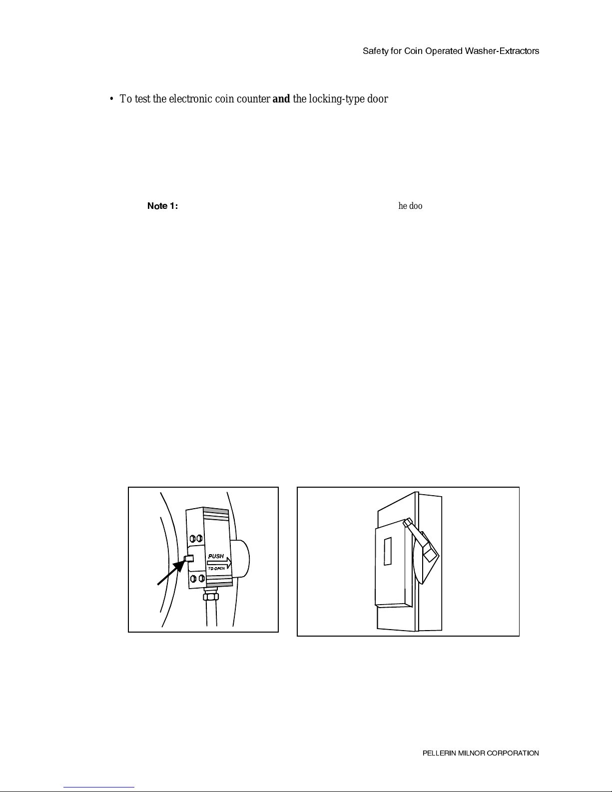
• To test the electronic coin counter
all of the following steps, in order.
Step 1.
Step 2.
Make sure that power is ON to your machine.
Close the door.
If the machine starts, let it run to the end of the cycle, then proceed to Step 3. (This may
a.
Do not insert coins.
the locking-type door interlock (monthly), perform
and
Do not skip any step.
have been simply a restart in mid cycle—when electric power is restored after a power
interruption while the machine was
=^cT )
possibility of a free wash when electric power is restored after a power interruption while the machine
was
If the machine does not start, proceed to step 3.
b.
Step 3.
Open the door. Now verify that the machine will not accept coins with the door open.
If the machine accepts coins when the door is open,
a.
and fix whatever is wrong.
Step 4 tests the possibility of a free wash simply by closing the door and Step 5 tests the
running.
not
(Perhaps the door switch is bad or the door switch actuator is
running
jammed making the switch think the door is closed.)
).
take it out of service, determine why,
Do not return the machine to service
until it successfully passes all seven steps described herein.
If the machine does not accept coins with the door open, proceed to Step 4.
b.
Step 4.
With the door open, manually operate the door switch actuator 100 times (Figure 1).
Operate the actuator for one second ON (depressed), then one second OFF (released). If the
machine completed steps 1, 2, and 3 successfully, this tests if simply closing the door will permit
a free wash.
If the machine starts while the door switch actuator is depressed,
a.
immediately take your
hand off the door switch actuator and take the machine out of service until the coin
counter has been changed. Do not return the machine to service until it successfully
passes all seven steps described herein.
If the machine does not start, proceed to Step 5.
b.
Figure 1: Door Switch Actuator Figure 2: Wall Mounted Power Disconnect Switch
Step 5.
With the door closed and the machine still in the “unarmed” condition (it has not yet
accepted coins), turn the power ON and OFF 25 times at the wall-mounted power disconnect
switch (Figure 2) or external circuit breaker. Turn power ON for five seconds, then OFF for five
seconds). Observe if the machine starts at any time the power is turned ON. This tests if the coin
counter will give a free wash when electric power is restored after power interruption while the
machine was
running.
not
@5<<5B9> =9<>?B 3?B@?B1D9?>
Page 11

CQVUdi V_b 3_Y^ ?`UbQdUT GQcXUb5hdbQSd_bc
If the machine starts without coins at any time as power is turned ON,
a.
take the machine
out of service until the coin counter has been changed. Do not return the machine to
service until it successfully passes all seven steps described herein.
If the machine does not start without coins at any time power was turned ON and OFF 25
b.
times, you probably have a good coin counter. Proceed to step 6.
Step 6.
Insert the proper number of coins. Verify that:
• the machine starts only after the last coin is accepted, and
• the machine will then accept no more coins.
If the machine starts before the last coin is accepted or accepts more than the proper
a.
number of coins,
take the machine out of service until you determine and fix what is
wrong. Do not return the machine to service until it successfully passes all seven steps
described herein.
If the coin counter functions properly and the machine starts,
b.
wait a full 2.5 minutes
proceed to step 7.
20DC8>= ' ) BRP[S 7PiPaSb
—Contact with hot bath liquor can scald you.
• During following step, hold the door firmly closed, as shown in Figure 3, to prevent door
from springing open if the latch retracts during this test.
Figure 3: Hold Door Shut When Testing the Door
Interlock
, then
Step 7.
After the machine has been running at least 2.5 minutes, and while manually holding the
door closed (Figure 3), attempt to depress the door unlock handle.
If the latch retracts,
a.
fixed. Do not return the machine to service until it successfully passes all seven steps
described herein.
If the latch does not retract, it is OK to return the machine to service (provided it also
b.
passes all other tests described herein).
=^cXRT ( ) 4]bdaT BPUT >_TaPcX^]
monthly
• To test
, both the coin counter
the locking-type door interlock (daily), perform Step 6 and 7.
only
• To test the electronic coin counter
all of the following steps, in order.
@5<<5B9> =9<>?B 3?B@?B1D9?>
take the machine out of service until the problem is diagnosed and
—Confirm
the door interlock function.
and
the locking-type door interlock (monthly), perform
and
, the door interlock function. Confirm
daily
Do not skip any step.
— End of BIRMCS01 —
Page 12

Page 13

Section 1
Commissioning
Page 14

MSOP0503AE/9274AV (1 of 1)
ÈTHE C4A ELECTRONIC COIN
WASHER-EXTRACTOR CONTROL
All controls and displays for operation of the C4A are visible on the front panel (FIGURE 1). Controls
and indicator lights for the M4A (single formula, non-coin) machine are shown in FIGURE
Detailed explanations of the following items are given throughout this manual.
ÊNameplate Controls
ËRun/Test Keyswitch—When this keyswitch and the Run/Attendant keyswitch are set to “Run,” the
machine operates normally. When this keyswitch is set to “Test” and the Run/Attendant keyswitch is set to
“Attendant,” a qualified service technician may view the software version and troubleshoot certain machine
functions by actuating displays, inputs, outputs, and functional tests.
ËTest Button—Depress this button to scroll among available tests (displays, inputs, and outputs) when
the Run/Test keyswitch and the Run/Attendant keyswitch are set to “Test” and “Attendant,” respectively.
ËRun/Attendant Keyswitch—When set to “Run,” the machine operates normally, requiring coins
for starting. When set to “Attendant,” the optional push-button (START button) operation is enabled. This
keyswitch must be set to “Attendant” to access the testing and troubleshooting functions of the control.
ËTO REDUCE SUDS Button—Used during normal operation to reduce the level of suds in the
machine to a level below the “Suds Level” line on the loading door glass, thus increasing washing efficiency.
During output testing, this button is used to toggle individual outputs and functional tests ON and OFF.
ËSTART Button (optional)—This button (optional, not shown) is enabled when the Run/Attendant
keyswitch is set to “Attendant.” It allows an attendant to operate the machine without coins.
ËSelect Temperature Buttons—These three buttons allow the user to select the appropriate first
bath water temperature for the goods loaded.
ÊDisplay
ËDeposit Coins Display—When the machine is ready for normal operation (not running a wash
cycle), these two digits display the number of coins required to start the machine. When the machine is
running a wash cycle, this display is dark. In Test mode, this display is dark except for two flashing decimals.
ËTime Remaining Display—During normal operation, this display shows the number of minutes
remaining in the current wash cycle. When the machine is in Test mode, the individual segments of this
display represent inputs, and illuminate as inputs are made.
ËMachine Status Display—During normal operatio n, this display shows which step of the wash
cycle the machine is currently performing. When the machine is in Test mode, this display is dark except for
a single flashing decimal.
ÎFIGURE 1 (MSOP0503AE)
ÎNameplate of C4A Models
Page 15

Section 2
Operating
Page 16

MSOP0502AE/9274AV (1 of 3)
ÈOPERATION OF C4A ELECTRONIC COIN WASHER-EXTRACTOR
ENTANGLEMENT HAZARD—The linen inside or hanging partially outside a
turning cylinder can suddenly wrap around you hand, arm, or body and twist
off/sever it. You can be killed or seriously injured.
ÊThe Power Up Sequence
Control circuit is
energized when power
is applied
Software version (20003) is displayed for 80 seconds after
power is applied. This safety delay prevents operation during
this time.
After 80-second
safety delay
The display flashes the number of coins (example: 15) required.
“C” (Close Door) flashes if door is open. See “HOW TO SET
REQUIRED NUMBER OF COINS” (see Table of Contents).
ÊHow To Start a Wash Cycle
Load machine
and close door
Load machine at or near rated capacity. Overloading or underloading may reduce efficiency.
Select bath
temperature
Select water temperature according to the goods loaded.
NOTE: As a factory-supplied option, the machine may be
equipped for second and third baths to be cold only, regardless
of the temperature selected.
Deposit coins Operation begins when last coin is accepted. When first coin
is accepted, display stops flashing and counts down number of
coins inserted. Coins are rejected if the door is open. The
door locks 1 minute after the machine accepts the last coin.
ËHow To Counteract Oversuds—If the suds level in the machine exceeds the “Suds Level” line on the
loading door, reduce the suds level.
Press “TO REDUCE
SUDS” button on
control panel
The drain opens for 10 seconds, then closes. Machine refills
after drain closes.
NOTE: Suds reduction can be used a maximum of three times
during each bath step.
ËHow To Start by Pushbutton (optional)—Pushbutton start is available as an option on all current coin
machine models. The following procedure applies only if your machine is equipped with this option.
Set Run/Attendant keyswitch to “Attendant”
position, and press the Start button.
Pushbutton start feature does not affect normal coin-start
operation, which works with keyswitch in either position.
Page 17

ÊDescription of Wash Formula
FIGURE 1 shows timing and operation of the standard wash cycle. During operation, the Deposit Coins dis-
play is blank and the Time Remaining display counts down minutes. The decimal flashes when the timer is counting.
ÏWash Formula for 30015C4A and 30020C4A Models
Operation Time Coast Time
Selected Temperature
Hot Warm Cold
Bleach/Suds bath 6:00 1:00 Hot Split Cold
Low-speed extract 1:00 0:30 — — —
Rinse 2:00 1:00 Split Split Cold
Low-speed extract 1:00 0:30 — — —
Softener bath 2:00 1:00 Cold Split Cold
High-speed extract 6:00 1:20 — — —
Total Time 18 :00 + 5:20 = 23:20 As a factory option, second and third baths may be
cold only.
ÎFIGURE 1 (MSOP0502AE)
ÎWash Cycle Timing for C4A Models
OPERA TION OF C4A ELE C TRONI C COI N W ASHER-EXT RACTO R MSOP0502AE/9274AV (2 of 3)
Page 18

ÊThe Power Restoration Sequence
ËIf Machine Memory Is Corrupt—If the machine lose s power while a wash cycle is runnin g and
microprocessor memory is corrupt (current wash cycle is not retained), the machine resets as shown in “The Power
Up Sequence” in this section. The microprocessor memory will remain intact approximately 24 hours without
power.
ËIf Machine Memory Is Intact AND Door Is Closed—If the machine loses power while a wash cycle
is running, and the wash cycle in progress is retained by the microprocessor, the control checks the status of the door
latch when power is restored. If the control detects that the door is closed, the wash cycle resumes—after an
80-second safety delay—at the beginning of the step in which power was lost. If the control detects that the
door is open, the machine resets as shown in “The Power Up Sequence” in this section.
The drain opens as soon as the machine loses power, but if the power outage is brief, the liquor level may not
fall enough to open the level switch. If the level switch is made when power is restored, the display indicates a Level
Switch Fault (E3) until the liquor level in the cylinder falls enough to open the level switch. When the level switch
opens, the machine clears the error and resumes the wash cycle at the beginning of the step in which power was lost.
If the error does not clear automatically, see “TESTING THE INPUTS, OUTPUTS, AND THE DISPLAY ON THE
C4A ELECTRONIC COIN WASHER-EXTRACTOR.”
If power is lost during extract, the machine executes a recycle sequence shown below when power is restored:
1. Basket rotates clockwise at wash speed for 18.5 seconds.
2. Basket accelerates to distribution speed and maintains speed for 60 seconds.
3. Timer starts and basket accelerates to extract speed. If the interrupted step is a low-speed extract, the wash
cycle proceeds normally. If the interrupted step is a final (high-speed) extract, the machine maintains
low extract speed for 100 seconds, then accelerates to high extract speed.
ÊAccessing the Formula Count Accumulator
ËOperation—The Formula Count Accumulator (FIGURE 2) tracks the number of
times the wash cycle has been run. This cumulative counter automatically increments each time the final extract step begins. The accumulator may be viewed and
compared to previous readings to determine the number of wash cycles, up to 999.
After 999 counts, the accumulator resets to 000 when next incremented.
Because the accumulator is maintained in capacitor-backed memory, a brief
power loss should not affect the count. However, a power loss of more than 24 hours
may cause memory loss, in which case an Accumulator Warning message (E1) appears on the display to indicate that accumulator memory was corrupted and reset to
0. Clear this error as described in “Viewing and Clearing Counter” in this section.
ËViewing and Clearing Accumulator—The accumulator may be viewed only when a wash cycle is not
in progress and the machine is not in Attendant mode. To view the counter, open the door and turn the keyswitch to
“Attendant.”
To clear the accumulator or an accumulator error, open the door, turn the keyswitch to “Attendant” and press
OVERSUDS three times. The accumulator displays “000” until a wash cycle is run. Always check accumulator if
power has been off for several days.
ÎFIGURE 2 (MSOP0502AE)
ÎAccumulator Display
OPERA TION OF C4A ELE C TRONI C COI N W ASHER-EXT RACTO R MSOP0502AE/9274AV (3 of 3)
Page 19

MSIN0501AE/9274AV (1 of 2)
ÈHOW TO SET REQUIRED NUMBER OF COINS
For all electronic coin washer extractors, the number of coins required to start the wash cycle is determined by
a six-position DIP switch (SW1) on the processor board (see FIGURE 1). Each position of the DIP switch (numbered 1-6) represents a specific number of coins, as shown in the Table of Sample Coin Count Settings in this
section. The total number of coins required to operate the machine for one wash cycle may be set from one to 63,
inclusive. The required count is represented by the total of all switches set to the ON position.
SHOCK HAZARD may cause severe injury.
☞ Lock OFF and tag out machine power at wall disconnect before removing
panels.
Using a small insulated screwdriver or wooden pencil, set the DIP switch for the desired number of coins. See
the Table of Sample Coin Count Settings in this section for available settings.
NOTE: The processor board to which the DIP switch is mounted is normally concealed by a dust cover.
This dust cover must be removed to gain access to the DIP switch, and must be replaced to prevent dust
accumulation on the processor board.
ÎFIGURE 1 (MSIN0501AE)
ÎDIP Switch (Positions 2 and 4 ON=10 coins)
Page 20

ÏT able of Sample Coin Count Settings
Coin Count
Switch Position and Number of Coins Represented
Position 1
(1 coin)
Position 2
(2 coins)
Position 3
(4 coins)
Position 4
(8 coins)
Position 5
(16 coins)
Position 6
(32 coins)
1 coin ✔
6 coins ✔✔
8 coins ✔
10 coins ✔✔
12 coins ✔✔
16 coins ✔
18 coins ✔✔
20 coins ✔✔
24 coins ✔✔
30 coins ✔✔✔✔
36 coins ✔✔
42 coins ✔✔✔
48 coins ✔✔
51 coins ✔✔ ✔✔
63 coins ✔✔✔✔✔✔
HOW TO SET REQUIRED NUMBER OF COINS MSIN0501AE/9274AV (2 of 2)
Page 21

Section 3
Troubleshooting
Page 22

MSTS0501AE/9274AV (1 of 5)
ÈTESTING DISPLAY, INPUTS, AND OUTPUTS
ON THE ELECTRONIC COIN WASHER-EXTRACTOR
The C4A electronic coin washer-extractor control includes several diagnostic features to aid in troubleshoot-
ing equipment problems. Procedures for using the following diagnostics are explained in this section:
1. How To View the Software Version—allows verification of software version and machine configuration
2. How To Exit the Testing Procedure—ends the testing procedure from any test.
3. How To Test the Displays—verifies that display is fully operational
4. How To Test the Microprocessor Inputs—verifies ON/OFF condition of inputs, and
5. How To Test the Outputs—allows manual operation of machine outputs.
CRUSHING AND ENTANGLEMENT HAZARD may result in loss of fingers or
limbs.
☞ DO N OT operate t his machine wi thout all pane ls securely in pl ace. The
panels prevent access to the drive mechanism and hot components, including motors and solenoids.
☞ Ensure that all personnel are clear of the machine before restarting after
service.
SHOCK HAZARD may result in serious injury.
☞ Lock OFF and tag out machine power at wall disconnect.
☞ NEVER remove panels without turning OFF all power to the machine.
Page 23

ÊHow To View the Software Version
As MILNOR®makes improvements to the software which controls these machines, the software version num-
ber changes. This information is often very helpful in troubleshooting errors and malfunctions.
ËViewing Software Version During Power Up—When power is first applied to the machine, the dis-
play will appear similar to FIGURE 1. This number is the software version; it will remain on the display for 80
seconds, then the normal operating display will appear.
ËViewing Software Version After Power Up—The software version can also be viewed after the
power up sequence has finished provided the machine is not running a wash cycle.
1. Set the Attendant keyswitch to
“Attendant.”
2. Set the Run/Test keyswitch to
“Test.”
The software version will
remain on the display until the Test
button is pressed.
ËHow To Interpret the
Software Version
—The first
digit in the Deposit Coins display
represents the machine class. In the
case of 30015C4A and 30020C4A
models, this number is “2.” The
second digit in the Deposit Coins display is ignored for these models. The two digits in the Time Remaining display,
along with the single digit in the Machine Status display, make up the revision of the software.
NOTE: If the first digit in the Time Remaining display is an alphabetic character (A-Z), the software is
non-standard; therefore, the wash cycle may not be the same as that described in “OPERATION OF C4A
ELECTRONIC COIN WASHER-EXTRACTOR” (see Table of Contents).
ÊHow To Exit the Testing Procedure
The machine may be returned to Automatic mode at any time during testing by switching the Run/Test and
Attendant keyswitches to “Run.”
ÎFIGURE 1 (MSTS0501AE)
ÎSoftware Version Display (Typical)
TESTING DISPLAY, INPUTS, AND OUTPUTS
ON THE ELECTRONIC COIN WASHER-EXTRACTOR MSTS0501AE/9274AV (2 of 5)
Page 24

ÊHow To Test the Displays
C4A models are equipped with a Test button beneath the Run/Test keyswitch, as shown in FIGURE 2. Press
this button once to begin testing the light emitting diode (LED) displays. All five digits will simultaneously display
“1,” then “2,” etc., counting upward then repeating the
sequence. All digits should be identical at any time.
Press Test to end the Display Test and start the Input
Test.
ÊHow To Test the
Microprocessor Inputs
During this test each input signal to the
microprocessor lights a specific segment of the Time
Remaining display (see Figure 3 and Table of
Microprocessor Inputs in this section).
In Test mode with the input test active, the
Deposit Coins display is dark except for two flashing
decimal points (DP1 and DP2). Likewise, the Machine
Status display is dark except for the flashing decimal.
If no inputs other than Test Mode are made, the Time Remaining
display appears as shown in Figure 3 immediately upon beginning the
input test sequence. Segment A2 corresponds to Test Mode; when this
segment lit, the machine is functioning normally in Test mode. Other
segments of the display represent other microprocessor inputs, as listed
in the Table of Microprocessor Inputs in this section. Manually actuate
each input for testing, and verify that the corresponding segment of the
Time Remaining display illuminates.
Segment A1 (OFF) represents the status of the Test button. Because the Test button scrolls the con trol through the available tests,
pressing it after the input test is selected will advance the control to the
output test without lighting segment A1. Assume that the Test button is
operating correctly if the control switched from the display test to the
input test when the Test button was pressed.
Alternatively, press and HOLD the Test button while in the display test. Segment A1 will remain illuminated as long as the Test button
is held.
ÎFIGURE 2 (MSTS0501AE)
ÎTesting Controls—C4A Models
ÎFIGURE 3 (MSTS0501AE)
ÎTime Remaining Display
(Input Test Mode)
TESTING DISPLAY, INPUTS, AND OUTPUTS
ON THE ELECTRONIC COIN WASHER-EXTRACTOR MSTS0501AE/9274AV (3 of 5)
Page 25

ÏTable of Microprocessor Inputs
Segment
Illuminated Input Name
Connector-
Pin
Input Status when
Illuminated
A1 Test Button (SHPS) MTA4-6 Test button depressed. (This input can be
tested only if the Test button is HELD
DEPRESSED while in the display test.)
B1 Door Interlock (CRDL) MTA4-5 Door is closed.
C1 Run/Attendant Keyswitch (SK01) MTA4-4 Keyswitch set to “Attendant.”
D1 not used — —
E1 Low Water Level Switch(SPLL) MTA4-2 Low level switch (SPLL) is made.
F1 Start Button (SHS+; optional) MTA4-1 Optional Start button is depressed
G1 not used — —
A2 Run/Test Keyswitch (SKM0) MTA5-6 Machine is in Test mode.
B2 Oversuds Button (SHDR) MTA5-5 Oversuds button is depressed.
C2 not used MTA5-4 —
D2 Normally-open Coin Switch
(SMS$; 1-7)
MTA5-3 Normally-open contact on coin mechanism
is closed.
E2 not used — —
F2 Normally-closed Coin Switch
(SMS$; 4-7)
MTA5-1 Normally-closed contact on the coin
mechanism is open.
G2 not used — —
ÊHow To Test the Outputs
Press the Test button to enter the output test from the input
test. When the output test is active, the Deposit Coins display
flashes “00.”
The Table of Manual Outputs in this section lists the tests
of output relays and systems. Press the Test button to scroll the
appropriate test (see Table of Manual Outputs) into the Time
Remaining display. Press TO REDU CE SUDS to toggle the
ON/OFF status of the output or functional test. Press the Test
button to turn the output OFF and advance to the next output or
functional test.
In Test mode, the door locks when either motor is energized, and remains locked for 10 seconds after the motor is deenergized. When the door is closed, certain relays operate in
combination; all relays function individually when the door is
open. Functional tests 17 and 18 are not available when the door
is open.
ÎFIGURE 4 (MSTS0501AE)
ÎTime Remaining Display Segments
TESTING DISPLAY, INPUTS, AND OUTPUTS
ON THE ELECTRONIC COIN WASHER-EXTRACTOR MSTS0501AE/9274AV (4 of 5)
Page 26

ÏT able of Manual Outputs
Test
Number
Output Relay Relay Name or
Functions Tested
Result or Test Sequence
Relay/Test status shown in “Machine Status”
01 K0 Clutch 0=engage extract clutch 1=engage wash clutch
02 K1 Cold water valve 0=close cold water valve 1=open cold water valve
03 K2 Hot water valve 0=close hot water valve 1=open hot water valve
04 K3 Coin rejector solenoid 0=accept subsequent
coins
1=reject subsequent
coins
05 K4 Not used None
06 K5 Not used None
07 K6 Not used None
08 K7 Not used None
09 K8 Extract Basket turns clockwise. Energize clockwise wash
relay (CRWAC) and engage extract clutch.
10 K9 Distribution Basket turns clockwise. Energize extract relay
(CREX) energized and engage wash clutch.
11 K10 Clockwise wash Basket turns clockwise. Clockwise wash relay
(CRWAC) energized and wash clutch engaged.
12 K11 Counter-clockwise wash Basket turns counter-clockwise. Energize
counter-clockwise wash relay (CRWAA) and
engage wash clutch.
13 K12 Not used None
14 K13 Not used None
15 K14 Drain solenoid 0=open drain valve 1=close drain valve
16 K15 Door interlock 0=unlock door 1=lock door
17 Functional test Water valves, drain
solenoid, level switch,
and reversing wash
speed
Door must be closed for this test.
• Engage wash clutch and open water valve(s).
• Basket reverses; water shuts off at level
• Open drain if oversuds pressed, machine
refills when released.
18 Functional test Extract speeds and vibra-
tion switch
Door must be closed for this test.
• Energize clockwise wash relay and energize
clutch for 20-second clockwise wash speed
• Energize distribution relay for 20-second
distribution speed
• De-energize clutch and distribution relay, and
energize CRWAC for 20-second low extract
• De-energize CRWAC and energize CREX for
high extract
• If vibration switch is manually tripped during
high extract, CRWAC replaces CREX in circuit,
yielding low extract
TESTING DISPLAY, INPUTS, AND OUTPUTS
ON THE ELECTRONIC COIN WASHER-EXTRACTOR MSTS0501AE/9274AV (5 of 5)
Page 27

MSTS0502AE/9274AV (1 of 2)
ÈHOW TO CORRECT ERRORS
WITH THE C4A CONTROL
ÊLoading Door Open During Operation
If the loading door should open during operation, the basket stops, the
program timer stops, and the drain opens. The Machine Status display shows
“C” (Close Door), as shown in FIGURE 1. When the door is closed, operation
resumes from where it was interrupted.
ÊOther Error Conditions
If an error other than “Loading Door Open” occurs, the Time Remaining display flashes an error code corresponding to the error, and the Machine Status display alternately flashes “E” (Error) and “U” (Unload).
Ë“Accumulator” Warning
formula count
accumulator memory
was corrupted and
accumulator was reset
to “000”
This error may be caused by a protracted lack of power to the processor
board, or when the machine is first started after the processor board is
replaced (see “Accessing the Formula Count Accumulator” in “OPERATION OF C4A ELECTRONIC COIN WASHER-EXTRACTOR” (see
Table of Contents)). Manually clear the accumulator to correct this error:
1. Open loading door, and set Run/Attendant keyswitch to “Attendant.”
2. Press “To Reduce Suds” button three times.
3. Return keyswitch to “Run.”
Ë“Coin Switch” Fault
coin switch not
responding properly,
subsequent coins are
rejected
1. Check for sticking for faulty coin switch.
2. Check input wiring and connections.
3. Correct error.
4. Turn Run/Attendant keyswitch to “Attendant” then to “Run” to clear
display.
Time
Remaining
Machine
Status
Time
Remaining
Machine
Status
Time
Remaining
Machine
Status
USE
QUARTERS
ÎFIGURE 1 (MSTS0502AE)
ÎDoor Open Error Display
Page 28

Ë“Level Switch” Fault
level switch normally
open contact is
CLOSED.
Check for faulty level switch. Replace if necessary.
Ë“Too Long to Fill” Error
maximum fill time
(10 minutes)
exceeded
Software Date Codes before 20003: Operation terminates. Door unlocks after 15 seconds with operation disabled during delay.
Software Date Codes 20003 and later: Machine continues to fill with
water, basket reverses at wash speed. Error clears without manual intervention when level is achieved.
Corrective Action: Check inlet water pressure, and check debris screens
on inlet tubing.
Ë“Too Long to Drain” Error
maximum drain time
(40 seconds) exceeded
Operation terminates, door unlocks after 15 seconds with operation disabled during delay. Check for clogged drain line or stuck drain valve.
Corrective Action: Turn Run/Attendant keyswitch to “Attendant” then
back to “Run” to clear display.
Time
Remaining
Machine
Status
Time
Remaining
Machine
Status
Time
Remaining
Machine
Status
HOW TO CORRECT ERRORS
WITH THE C4A CONTROL MSTS0502AE/9274AV (2 of 2)
Page 29

Section 4
Supplemental Information
Page 30

MSFD0503AE/9274AV (1 of 2)
ÈTHE HARDWARE IN C4A ELECTRONIC COIN
WASHER-EXTRACTOR CONTROLS
ÊGeneral
The MILNOR® C4A microprocessor control is designed specifically for MILNOR machines. Along with
certain external electromechanical relay logic and sensing devices, they control all machine and system functions.
Not every microprocessor includes all the following components.
ÊThe Microprocessor Components
Ë1. Keyswitches—The RUN/ATTE NDANT keyswitch and the RUN/TEST keyswitch allow access to the
RUN and TEST modes only by authorized personnel. The RUN/ATTENDANT key may be removed only in RUN,
and the RUN/TEST key may be removed only in RUN. Never leave keys accessible to unauthorized personnel.
Ë2. Display—The display is light emitting diode (LED).
Ë3. Power Supply—Converts control circuit AC voltage to +12VDC, -12VDC, and +5VDC for the CPU board.
The power supply is auto switchable between 120VAC and 240VAC.
Although the +12VDC and -12VDC are not adjustable, the +5VDC is rather sensitive and the power supply
must be adjusted most accurately, so that the actual voltage at the Power Supply and at the CPU board is
between 5.04 VDC and 5.06VDC as measured by an accurate digital voltmeter; otherwise the machine will
likely malfunction.
Ë4. CPU Processor Board—The Central Processing Unit (CPU) processes data received from the various
inputs, stores information, and responds to each pushbutton entry with the appropriate action. Data is stored in three
microprocessor chips, which reside on the CPU.
E-PROM—contains fixed instructions programmed by MILNOR® (software) that dete rmine how the
machine functions. Also contains the standard formulas for all industries.
S-RAM—stores the accumulator (formula count) data so long as the machine has power, or via a capacitor
for approximately 48 hours with power off. Also stores where machine was last when power is turned off at
machine.
Page 31

Ë5. Output Board—The 16 output relays are socket-mounted SPDT electromechanical relays with contacts
capable of faithfully conducting a maximum of 25VA (0.1 ampere or 100 milliamperes at 220/240VAC, or 0.2
amperes or 200 milliamperes at a maximum of 110/120VAC). The output will be either 220/240VAC or
110/120VAC depending on the machine model/type.
These outputs and their power source are intended only to drive another relay with higher contact ratings that,
in turn, may drive a pump, valve, solenoid, etc., from a separate power source. Never use these outputs to
directly drive a pump, valve, or solenoid unless the maximum current required never exceeds the above
values. Higher ampere or VA loads will burn out traces on the printed circuit board or possibly overload and
damage the control circuit transformer.
THE HARDWARE IN C4A ELECTRONIC COIN WASHER-EXTRACTOR CONTROLS MSFD0503AE/9274AV (2 of 2)
Page 32

MSSM0217AE/9020IV (1 of 5)
ÈHOW TO CHANGE EPROMS IN MICROPROCESSORS
AND WHERE TO CHECK THE DC VOLTAGES
Occasionally, software enhancements become available. Depending upon the software change, the new software EPROMs (Erasable, Programmable, Read-Only Memory) may be offered for sale or for no charge to the
customer. When a set of EPROMs is changed in the field, ensure that the software version being installed matches
the machine hardware and that EPROMs are installed in the proper socket positions and orientation.
ÊHow To Change EPROMs
SHOCK HAZARD—Electrical components on the machine conduct high voltage
that will kill or seriously injure you on contact.
☞ Lock OFF and tag out electrical power at the main (wall) disconnect before
beginning this procedure.
1. Make sure all power to the machine is off.
2. Locate the EPROMs as described in “Location of EPROMs on Proces-
sor Board” in this section. Note the orientation of the EPROMs as
shown in FIGURES 3, 5, 7, and 9.
D
G
B
E
3. Slip a small flat tool underneath the EPROM, and carefully remove
each old EPROM from its base, taking note of their numerical order
(see FIGURES 3 and 7) and orientation to the key notch on the socket.
4. Install new EPROMs, making sure the key notch on the EPROM is
properly oriented and that all pins enter the proper holes in the socket
(FIGURE 1). If necessary, slightly bend the pins on the EPROMs to
align them in the socket. After inserting each EPROM, verify that all
ÎFIGURE 1
ÎProperly Seating the EPROM
(MSSM0217AE)
pins are seated in the socket.
COMPONENT DAMAGE HAZARD—Incorrectly installing any EPROM may
cause EPROM burn out, machine failure, or display error.
☞ Match each EPROM with its corresponding socket. Each EPROM will
only one socket, although it may physically
fit
in others.
work
in
☞ Align EPROM so every pin mates with the correct hole in the socket.
ËVerifying Proper EPROM Installation
—After installing new EPROMs, apply power to the machine
and turn the machine on. If the EPROMs are properly installed, the display will continue with the normal display
sequence when powering up. If the display is blank or appears unusual, turn the machine off at once and check the
orientation of the EPROMs.
F
F
Page 33

HOW TO CHANGE EPROMS IN MICROPROCESSORS
AND WHERE TO CHECK THE DC VOLTAGES MSSM0217AE/9020IV (2 of 5)
B
C
ÊLocation of EPROMs on Processor Board
Depending on machine model and type, the CPU chip can be an Intel 8085 or an Intel 8088. Each microprocessor board requires at least one EPROM for proper operation, but the EPROMs are located differently, depending
upon the type of board. This information describes the location and arrangement of the EPROM chips on each type
of board. It also describes where to check the voltages required by the processor board.
Ë8085 Processor Boards,
NOT Coin Machine
—See FIGURE 3. Install EPROM #1 at the end of the
row, then #2, #3, and #4. Chip #4 goes next to the two soldered chips on the board. See FIGURE 2 for where to
check voltages.
ÎFIGURE 2
(MSSM0217AE)
ÎMTA-31 on 8085 Processor Board
(wires not shown for clarity)
ÎFIGURE 3
(MSSM0217AE)
Î8085 Processor Board (NOT Coin Machine)
Page 34

HOW TO CHANGE EPROMS IN MICROPROCESSORS
AND WHERE TO CHECK THE DC VOLTAGES MSSM0217AE/9020IV (3 of 5)
Ë8085
Coin Machine
Processor Boards
—See FIGURE 5. Install the single
EPROM in socket IC7 below connector W34. These boards have no battery.
DIP switch
ÎFIGURE 4
8085 chip
EPROM in
socket IC-7
MTA connectors
Chassis ground
(MSSM0217AE)
ÎMTA-1 in 8085 Coin Machine
(wires not shown for clarity)
ÎFIGURE 5
Î8085 Coin Machine Processor Board
H
Capacitor
(MSSM0217AE)
Page 35

HOW TO CHANGE EPROMS IN MICROPROCESSORS
AND WHERE TO CHECK THE DC VOLTAGES MSSM0217AE/9020IV (4 of 5)
B
Ë8088 Processor Boards
C
Without Memory Expansion Board
—See the table of EPROM loca-
tions (below) and FIGURE 7. If the set consists of only one EPROM, install it in socket A of FIGURE 7. If two
EPROMs comprise the set, install EPROM #2 in socket A and EPROM #1 in socket B. Always install highest
numbered EPROM in socket A. If the set consists of more than two EPROMs, a Memory Expansion Board must
be present in the machine along with the processor board.
Ë8088 Processor Boards
With Memory Expansion Board
—See the table of EPROM locations
below and FIGURE 7. If the EPROM set consists of three or more EPROMs, install the two highest numbered
EPROMs (e.g., EPROMs #3 and #4 of a four-chip set) on the processor board, with the highest numbered E-PROM
(EPROM #4 of a four-chip set) in socket A, and the EPROM with the second highest number (EPROM #3 of a
four-chip set) in socket B. Install the remaining EPROM(s) on the Memory Expansion Board with the highest
numbered of the remaining EPROMs (e.g., EPROM #2 of a four-chip set) in socket IC-1 on the Memory Expansion
Board and EPROM #1 in socket IC-2.
EPROM Locations on 8088 Processor Board
and Memory Expansion Board
E-PROM Location by Socket
(see FIGURE 4)
EPROMS in Set A B IC-1 IC-2
4-chip set 4321
3-chip set 3 2 1 —
2-chip set 2 1 ——
1-chip set 1 ———
ÎFIGURE 6
Î1MTA-31 on 8088 Board
(MSSM0217AE)
(wires not shown for clarity)
Î8088 Processor Board and Optional Memory Expansion Board
ÎFIGURE 7
(MSSM0217AE)
Page 36

R
HOW TO CHANGE EPROMS IN MICROPROCESSORS
AND WHERE TO CHECK THE DC VOLTAGES MSSM0217AE/9020IV (5 of 5)
Ë80186 Processor Boards
—This processor board
is used on all Milnor system controllers (Miltron, Mildata,
etc.) equipped with a color monitor, and on textile processing machines with software versions 95000 and later. The
single EPROM on this board is located in socket IC-2.
Chassis Ground
IMTA28
ÎFIGURE 8
(MSSM0217AE)
Î1MTA-31 on 80186 Board
1MTA31
Capacitor
2MTA31
1MTA32
1MTA33
(wires not shown for clarity)
1MTA34
1MTA29
MTA30
I
80186 Processor
ROM socket
(empty except
for Japan)
EPROM in
socket IC-2
MTA35
ÎFIGURE 9
MTA40
(MSSM0217AE)
MTA37
MTA36
MTA38
MTA39
Î80186 Processor Board
 Loading...