

Page 1
Published Manual Number/ECN: ME76CBW3AE/2019044A
• Publishing System: TPAS2
• Access date: 02/05/2019
• Document ECNs: Latest
Schematic/Electrical Parts
76028, 76039G3 & 92048G4
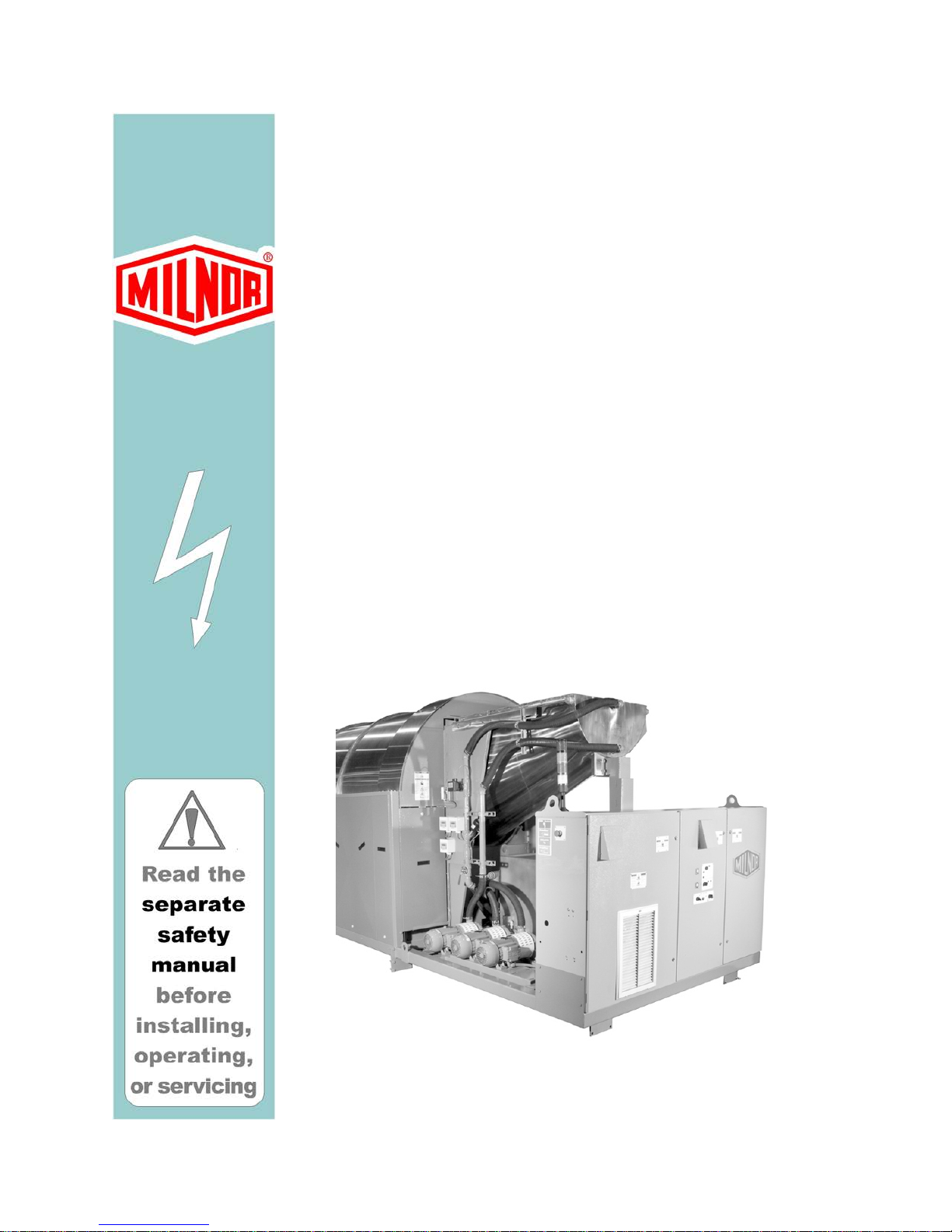
CBW® Continous Batch Washer
System
Mark 9 Controls
PELLERIN MILNOR CORPORATION POST OFFICE BOX 400, KENNER, LOUISIANA 70063-0400, U.S.A.
Page 2

Page 3

Table of Contents
ME76CBW3AE/19044A
Page Description Document
1 Component Parts List W9CBW3PL/2018383N
28 Limited Standard Warranty BMP720097/2019036
29 How to Get the Necessary Repair Components BIUUUD19/20081231
30 Safety—Continuous Batch Washer BIUUUS27PC/20051111
35 CBW to Press System Connections MSIN0911AE/1998247N
37 Special Load Interface Requirements for the Milnor
Centrifugal Extractor
40 Milnor Allied Interface Specifications and Signals, CBW BICALC02CL/20041008
53 Ecolab HELMS Data Interface BIPCUI07/2016022
56 How to Use Milnor® Electrical Schematic Diagrams BIUUUK01/20130308
68 Sample Schematic BMP010012/2018343
70 3 Phase Motor Connection Diagram BMP850029/1999362B
71 3P Motor Diagram-Multivolt W80008/2001253A
72 Cable Routings W9CBW3CC/1999133B
74 Control Box Layouts Sheet 1 W9CBW3TG1/2009173B
76 Control Box Layouts Sheet 2 W9CBW3TG2/2009173B
78 Control Box Layouts Sheet 3 W9CBW3TG3/2009173B
80 Control Box Layouts Sheet 4 W9CBW3TG4/2014385B
82 Control Box Field Wiring Hook-Ups W9CBW3TG5/2002045B
84 Inverter Box Layout W9CBW3TG6/2009233B
86 Main Control Box-Left W9CBW3TG7/2015253B
88 Main Control Box-Center W9CBW3TG8/2015253B
90 Main Control Box-Right W9CBW3TG9/2015253B
92 Allied Interface W9CBW3AI/2004416B
94 Allied Interface Weight Inputs W9CBW3AW/2011432B
96 Chemical Add Opitons W9CBW3CA/1999133B
98 Drive Contactors W9CBW3DA/2016122B
100 Variable Speed Drive Dyanmic Braking Resistors W9CBW3DB/2013063B
102 Drive Contactors for Baldor Drive W9CBW3DC/1999521B
104 Dynamic Braking Resistors for Baldor Drive W9CBW3DD/1999521B
106 Long Distance Incompatibility W9CBW3FA/2011432B
108 Press/Extractor Lg Distance Incompatibility W9CBW3FAA/2004076B
110 Dual Bath W9CBW3FB/2008483B
112 Main Flow / Flow Stop W9CBW3FC/2018192B
114 Flow/Flow Not Option W9CBW3FN/1999193B
116 Flow/Flow Not Option for PulseFlow W9CBW3FNA/2010243B
118 Steam Disinfect W9CBW3FS/2002045B
120 Overhead Fill Tank or Dual fill W9CBW3FT/2016494B
122 Interpert Relay Boards W9CBW3IA/1999286B
BICXUI01/20021226
Page 4

Table of Contents, continued
ME76CBW3AE/19044A
Page Description Document
124 Interpret Relays W9CBW3IB/2004364B
126 Module Controls Boards Wiring W9CBW3JA/2011432B
128 Typical 8/16 Board Inputs/Outputs W9CBW3JB/1999193B
130 Module Inputs/Outputs W9CBW3JC/2016122B
132 Typical 24 Output Board Wiring W9CBW3JD/2003445B
134 Conductivity / PH probe wiring W9CBW3JE/2016033B
136 Flush Enhance/Quick Refill W9CBW3JH/1999133B
138 Loading Flush Pump Interface W9CBW3LA/2016494B
140 Loading Conlo/Conwa Controls W9CBW3LB/2015184B
142 Loading Conlo/Conwa Controls w/ Inverter W9CBW3LBA/2014385B
144 Loading-Conwa Lights W9CBW3LC/2002453B
146 Loading-Conwa Lights W9CBW3LCA/2014385B
148 Loading Conlo/Cnwa Bag Inputs W9CBW3LD/2014385B
150 Loading Flush Pump+Drain & CD W9CBW3LF/2001356B
152 Flush Valves W9CBW3LG/1999133B
154 Load Chute Flaps W9CBW3LH/2017413B
156 Intermediate Loading Conveyor W9CBW3LI/2018042B
158 Load Flush with PulseFlow W9CBW3LP/2010385B
160 PulseFlow Tank to Load Chute W9CBW3LP1/2011432B
162 PulseFlow Mod. to Mod.Closes to Load End W9CBW3LP2/2016026B
164 PulseFlow Tank to Last Zone W9CBW3LP3/2018192B
166 PulseFlow Mod. to Mod.-Closes to Disch. End W9CBW3LP4/2016026B
168 PulseFlow Light Stand W9CBW3LP5/2015184B
170 PulseFlow slow down speed W9CBW3LP6/2015505B
172 Alternate Pulse Flow Pump W9CBW3LPA/2016026B
174 Alternate Pulse Flow Modules 1-8 W9CBW3LPA1/2013413B
176 Alternate Pulse Flow Modules 9-10 W9CBW3LPA2/2013355B
178 Load Flush with PulseFlow, Dual Tank W9CBW3LPD/2015474B
180 Pulse Flow Dual Tank W9CBW3LP1D/2018305B
182 Dual Pulse Flow Tank, 2 Pumps W9CBW3LP2D/2017322B
184 Dual Pulse Flow Tank, 2 Pumps W9CBW3LP3D/2018192B
186 Dual Loading Flush with PulseFlow, 2 Pumps W9CBW3LP4D/2017322B
188 Mentor Controls W9CBW3NA/2018406B
190 Mentor Board Wiring W9CBW3NB/2011432B
192 Mentor Board Wiring w/ solid state PC W9CBW3NBA/2016146B
194 Mentor Board Wiring w/ solid state PC+Moxa card W9CBW3NBB/2016146B
196 Q7 MENTOR Control W9CBW3NBC/2016454B
198 Mentor Microprocessor Inputs W9CBW3NC/2016202B
200 Mentor Diagnostic LCD Display W9CBW3ND/2001314B
Page 5

Table of Contents, continued
ME76CBW3AE/19044A
Page Description Document
202 Optional Flashing Signal W9CBW3NFS/2016194B
204 Reuse Tank to Drain Wiring W9CBW3RA/2003236B
206 Standard I/O Outputs W9CBW3SA/1999193B
208 Standard I/O Outputs (Sheet 2) W9CBW3SB/2016202B
210 Shaker Screen Interface<12-1-2018 W9CBW3SC/2019033B
212 Shaker Screen Interface >12-1-2018 W9CBW3SCA/2019044B
214 Emergency Stops W9CBW3SD/2017282B
216 Proximity Switches W9CBW3SE/2009196B
218 Remote Goods/Formula Selector W9CBW3SF/2016113B
220 Std I/O Board Wiring W9CBW3SG/1999286B
222 Remote Customer Selector W9CBW3SH/2016113B
224 Selection Of 2 Defferent Rotation Arcs W9CBW3SJ/1999193B
226 Modulating Water Valves W/ Flow Meters W9CBW3SK/2016454B
228 Vent Fans W9CBW3VF/2016223B
230 Power Distribution-Non Pulse Flow W9CBW3WA/2018195B
232 Power Distribution for Inverter Driven Ld Conveyor W9CBW3WAA/2009153B
234 Power Distribution-PULSE FLOW W9CBW3WAB/2019054B
236 600V CBW with Inverter W9CBW3WB/2014225B
238 Wash Water Flow Lifter Control W9CBW3ZA/2007104B
240 Rinse Zone Control Circuit W9CBW3ZB/1999321B
242 Rinse Zone Control Power W9CBW3ZC/1999133B
244 Drain Flowsplitter W9CBW3ZD/1999133B
246 Wash Water Flow Lifter Control With Drain W9CBW3ZE/2007104B
248 Work Wear Module For Rinse Zone W9CBW3ZF/1999321B
250 Rinse Zone Control Circuit With Drain No Surplus Pump W9CBW3ZG/1999321B
252 Hold Tank Wiring W9CBW3ZH/2008483B
254 Autobrush For Flowsplitter W9CBW3ZJ/1999193B
256 Rinse Zone W/ Drain & Reuse Tank W9CBW3ZW/1999321B
259 1. Maestro Modifications
260 Control Operation Tank A WINSMEWA/2004374B
262 Control Operation Tank A WINSMEWAA/2004374B
264 Control Operation Tank B WINSMEWB/2004374B
266 Control Operation Tank C WINSMEWC/2004374B
268 Loading-Flush Pump Workwear WINSMEWD/2004374B
270 Module Drains to Sewer/Tanks WINSMEWE/2004374B
272 Drain Header WINSMEWEA/2004374B
275 2. Lint Controller
276 Component Parts List W6LINTCONP/2017444N
Page 6

Table of Contents, continued
ME76CBW3AE/19044A
Page Description Document
278 Control Box Layouts W6LINTCONT/2017444B
280 Board to board wiring W6LINTCON1/2017444B
282 Lint Tank to Module Pump W6LINTCON2/2017473B
284 Module to Lint Tank W6LINTCON3/2017444B
286 Inputs/Outputs W6LINTCON4/2017444B
288 Magnetic Flow Meter W6LINTCON5/2017444B
290 Light Stand W6LINTCON6/2017444B
292 Lint Tank Level W6LINTCON7/2017444B
Page 7

W9CBW3PL/2018383N
U
T
FRONT OF TUNNEL
FRONT OF TUNNEL
Page 1 of 27
C O M P O N E N T P A R T S L I S T
>>CONTROL BOX LAYOUTS
01 DETAIL-MENTOR FRONT PANEL W9CBW3TG1 B2TAG99014 MENTOR CONTROL PANEL SEE FUNCTION
02 DETAIL-MENTOR BACK PANEL W9CBW3TG1 B2TAG99013 MENTOR POWER ENABLE PANEL SEE FUNCTION
03 DETAIL-FLUSH TANK INTERFACE BOX W9CBW3TG1 B2TAG99011 FLUSH TANK INTERFACE BOX SEE FUNCTION
04 DETAIL-MAIN C-BOX RIGHT (MODULE)SEC. W9CBW3TG2 B2TAG99017 G3 CBW MAIN C-BOX RIGHT SEE FUNCTION
COMPONENT FUNCTION OF WHERE TO FIND
NUMBER THIS COMPONENT THIS COMPONENT MILNOR P/N DESCRIPTION LOCATION
05 DETAIL-MAIN C-BOX LEFT (STD OUT) SEC W9CBW3TG2 B2TAG99018 G3 CBW MAIN C-BOX LEFT SEE FUNCTION
06 DETAIL-MAIN C-BOX MIDDLE (DRIVE) SEC. W9CBW3TG3 B2TAG99009 G3 CBW MAIN C-BOX MIDDLE SEE FUNCTION
07 DETAIL-INTERPRET RELAY BOX W9CBW3TG3 B2TAG99012 INTERPRET RELAY BOX SEE FUNCTION
08 DETAIL CONWA/CONLO BOX W9CBW3TG4 B2TAG92059 CONWA/CONLO CONTROL BOX SEE FUNCTION
09 DETAIL RINSE ZONE BOX W9CBW3TG4 B2TAG91057 MK8 CBW RINSE ZONE BOX SEE FUNCTION
10 DETAIL WASH WATER FLOW LIFTER W9CBW3TG4 B2TAG91058 MK8 CBW WASH WATER FLOW LIFTER SEE FUNCTION
11 DETAIL-MAIN C-BOX LEFT (PULSE FLW ) W9CBW3TG7 B2T2010013 CBW PULSE FLOW INVERTER CONTROLS SEE FUNCTION
13 DETAIL-MAIN C-BOX CENTER(PULSE FLW) W9CBW3TG8 B2T2010012 PULSE FLOW CONTROLS MIDDLE SECTION SEE FUNCTION
12 DETAIL-MAIN C-BOX CENTER(PULSE FLW) W9CBW3TG8 B2T2010016 PULSE FLOW CONTROLS MIDDLE SECTION SEE FUNCTION
1056 >>PULSE FLOW ANALIZERS
1056-1 ANALIZER DUAL CONDUCTIVITY W9CBW3JE 09XSCT0001 ROSEMOUNT 1056 DUAL INPUT BOTH COND
1056-2 ANALIZER DUAL PH W9CBW3JE 09XSCT0002 ROSEMOUNT 1056 DUAL INPUT BOTH PH FRONT OF TUNNEL
1056-3 ANALIZER DUAL PH W9CBW3JE 09XSCT0002 ROSEMOUNT 1056 DUAL INPUT BOTH PH FRONT OF TUNNEL
1056-4 ANALIZER DUAL IN CONDUCTIVITY/PH W9CBW3JE 09XSCT0003 ROSEMOUNT 1056 DUAL INPUT CONDUCTIVI
BA >>PRINTED CIRCUIT BOARDS
BAD-* BOARD-TYPICAL ANALOG TO DIGITAL (TEMP) W9CBW3JA 08BSADCT BD:SERIAL A-D CONVERT->TEST MAIN CNTRL BOX
BAD-* BOARD-TYPICAL ANALOG TO DIGITAL W9CBW3JE 08BSADCT BD:SERIAL A-D CONVERT->TEST MAIN CNTRL BOX
BAD-0 BOARD-ANALOG TO DIGITAL CONVERTER W9CBW3NB 08BSADCLT BD:SER A-D+LOAD CELL->TESTED MENTOR CNSOLE
BAD-0 BOARD-ANALOG TO DIGITAL CONVERTER W9CBW3NBA 08BSADCLT BD:SER A-D+LOAD CELL->TESTED MENTOR CNSOLE
BAD-0 BOARD-ANALOG TO DIGITAL CONVERTER W9CBW3NBB 08BSADCLT BD:SER A-D+LOAD CELL->TESTED MENTOR CNSOLE
BARS BOARD PROBE RESISTOR W9CBW3JE 08BNCNPHAT PROBE RESISTOR BOARD MAIN CNTRL BOX
BBB BOARD-BATTERY BACKUP W9CBW3NB 08BSBB1T BOARD: SER BATT BACKUP-TEST MENTOR CNSOLE
B-CMR VIDEO CAMERA-SEALED ASSEMBLY W9CBW3NBB ZXUUACSZVA SEALED CAMERA POWER OVER ETHERNET LOOSE FIELD INST
BDA-1 BOARD-DIGITAL TO ANALOG CONVERTER W9CBW3SK 08BSDACT BD:SERIAL D-A CONVERTR->TEST MAIN CNTRL BOX
BFAD-* BOARD-TYPICAL A/D FOR OVERHEAD FILL W 9CBW3FT 08BSADCT BD:SERIAL A/D CONVERT->TEST MAIN CNTRL BOX
14 DETAIL-MAIN C-BOX RIGHT(PULSE FLW) W9CBW3TG9 B2T2010014 PULSE FLOW PROCESSOR CONTROLS SEE FUNCTION
15 DETAIL-MAIN C-BOX RIGHT(PULSE FLW) W9CBW3TG9 B2T2010015 PULSE FLOW INTERPRET RELAY PANEL SEE FUNCTION
BHIO-1 BOARD-HIGH SPEED 8-16 W9CBW3SK 08BS816CHT BD 8OUT-16IN HIGH SPD->TESTD MAIN CNTRL BOX
1
Page 8

W9CBW3PL/2018383N
O
O
O
O
8
MAIN CNTRL BOX
MAIN CNTRL BOX
MAIN CNTRL BOX
MENTOR CNSOLE
MENTOR CNSOLE
Page 2 of 27
C O M P O N E N T P A R T S L I S T
COMPONENT FUNCTION OF WHERE TO FIND
NUMBER THIS COMPONENT THIS COMPONENT MILNOR P/N DESCRIPTION LOCATION
B-HUB HUB-4 PORTS+4PoE PORTS W9CBW3NBB 08PCSW4P4P SWITCH 4 PORTS 4 POE MENTOR CNSOLE
BIO-* BOARD-TYPICAL 8OUT / 16 INPUT W9CBW3JA 08BS816CT BD:SERIAL 8OUT-16INPUT-TEST MAIN CNTRL BOX
BIO-4 BOARD-STD 8OUT / 16 INPUT 4 W9CBW3AW 08BS816DT SERIAL 8OUT-16INPUT-TESTED SURFACE M
BIO-A BOARD-STD 8OUT / 16 INPUT A W9CBW3SG 08BS816DT SERIAL 8OUT-16INPUT-TESTED SURFACE M
BIO-B BOARD-STD 8OUT / 16 INPUT B W9CBW3SG 08BS816DT SERIAL 8OUT-16INPUT-TESTED SURFACE M
BIO-E BOARD-STD 8OUT / 16 INPUT E W9CBW3NBC 08BS816DT SERIAL 8OUT-16INPUT-TESTED SURFACE M
BMTH-0 BOARD-MENTOR MOTHER W9CBW3NB 08BS3MTHAT SER 3 CARD MOTHER BD->TEST MENTOR CNSOLE
BMTH-0 BOARD-MENTOR MOTHER W9CBW3NBA 08BS3MTHAT SER 3 CARD MOTHER BD->TEST MENTOR CNSOLE
BMTH-0 BOARD-MENTOR MOTHER W9CBW3NBB 08BS3MTHAT SER 3 CARD MOTHER BD->TEST MENTOR CNSOLE
BMTH-0 BOARD-MENTOR MOTHER W9CBW3NBC 08BS3MTHAT SER 3 CARD MOTHER BD->TEST MENTOR CNSOLE
BMTH-1 BOARD-MODULE MOTHER W9CBW3FT 08BS8MTHAT BD:SERIAL 8 CARD MOTHER-TEST MAIN CNTRL BOX
BMTH-1 BOARD-MODULE MOTHER W9CBW3JA 08BS8MTHAT BD:SERIAL 8 CARD MOTHER-TEST MAIN CNTRL BOX
BMTH-1 BOARD-MODULE MOTHER W9CBW3JE 08BS8MTHAT BD:SERIAL 8 CARD MOTHER-TEST MAIN CNTRL BOX
BMTH-A BOARD-STANDARD MOTHER W9CBW3SG 08BS5MTHAT BD:SERIAL 8 CARD MOTHER-TEST MAIN CNTRL BOX
BO24-* BOARD -TYPICAL 24 OUTPUT W 9CBW3JA 08BSO24AT BD:SERIAL 24 OUTPUT->TEST MAIN CNTRL BOX
BO24-0 BOARD-24 OUTPUT FOR ALLIED INTERFACE W9CBW3AI 08BSO24AT BD:SERIAL 24 OUTPUT->TEST MAIN CNTRL BOX
BO24-6 BOARD-24 OUTPUT FOR ALLIED INTERFACE W9CBW3AI 08BSO24AT BD:SERIAL 24 OUTPUT->TEST MAIN CNTRL BOX
BPB BOARD-186 PROCESSOR BOARD W9CBW3NB 08BSPDET 186 SERIAL PROCESSOR-TESTED MENTOR CNSOLE
BPB BOARD-186 PROCESSOR BOARD W9CBW3NBA 08BSPE2T PROC BD+FP->TEST MENTOR CNSOLE
BPB BOARD-186 PROCESSOR BOARD W9CBW3NBB 08BSPG1T BD:ARM7 SERIAL PROCESSOR->TEST MENTOR CNSOLE
BPB BOARD-Q7 PROCESSSOR W9CBW3NBC 08BHGQ7BS Q7 PROCESSOR WITH 10.4 DISPLAY 1024X76
B-PC PERSONAL COMPUTER W9CBW3NB 08PC806233 PC P6-233 INDUSTRIAL PC MENTOR CNSOLE
B-PC SOLID STATE COMPUTER+UPS W9CBW3NBA 08PC80427K PC-SIEMENS SIMATIC ASSY MENTOR CNSOLE
B-PC SOLID STATE COMPUTER+UPS W9CBW3NBB ECBW12SSPC ASSY SIMATIC IPC427C W/ SERIAL CARD MENTOR CNSOLE
B-PRN PRINTER-MENTOR W9CBW3NB 08MPARRLIJ PRINTER-OKIDATA OKIPAGE #6EX LOOSE FIELD INST
B-PRN PRINTER-MENTOR W9CBW3NBA 08MPARRLJ PRINTER-BROTHER #HL 2240D LOOSE FIELD INST
B-PRN PRINTER-MENTOR W9CBW3NBB 08MPARRLJ PRINTER-BROTHER #HL 2240D LOOSE FIELD INST
BSD BOARD-STM DISINFECT BATTERY BACKUP W9CBW3FS 08B1BSDT BOARD;M6 CBW STEAM DIS TEST MENTOR CNSOLE
BSM-1 BOARD SUMMING LOAD CELL W9CBW3NB 08BDSB SUMMING BD. UP TO 4 LOAD CELL MENTOR CNSOLE
BSM-1 BOARD SUMMING LOAD CELL W9CBW3NBA 08BDSB SUMMING BD. UP TO 4 LOAD CELL MENTOR CNSOLE
BSM-1 BOARD SUMMING LOAD CELL W9CBW3NBB 08BDSB SUMMING BD. UP TO 4 LOAD CELL MENTOR CNSOLE
CB >>>CIRCUIT BREAKERS
CB02 CIRCUIT BRK-120V STD I/O BOX W9CBW3SA 09FM05BKGR CKT BRK 5A240VBLK/BEZ-GRAY/BTN MAIN CNTRL BOX
2
Page 9

W9CBW3PL/2018383N
Page 3 of 27
C O M P O N E N T P A R T S L I S T
CBFC1 CIRCUIT BRK-WASH FLOW BX 120V W9CBW3ZA 09FM02BKBK CKT BKR 2 AMP 240V WASH WATER BX
CBFC1 CIRCUIT BRK-WASH FLOW BX 120V W9CBW3ZE 09FM02BKBK CKT BKR 2 AMP 240V WASH FLOW BX
COMPONENT FUNCTION OF WHERE TO FIND
NUMBER THIS COMPONENT THIS COMPONENT MILNOR P/N DESCRIPTION LOCATION
CB1 CIRCUIT BRK-SHAKER SCREEN+PUMP W9CBW3SC 09FC032CAA IEC MINI CIR.BREAK 32A 480V3P SKR SCREEN BX
CBC CIRCUIT BRK-CONTROL CIRCUIT W9CBW3WAA 09FC010CAA IEC MINI CIR.BREAK 10A 480V3P MAIN CNTRL BOX
CB37 CIRCUIT BRK-MODULE CONTROL BOX W9CBW3JB 09FM05BKGR CKT BRK 5A240VBLK/BEZ-GRAY/BTN MAIN CNTRL BOX
CBC CIRCUIT BRK-CONTROL CIRCUIT W9CBW3WA 09FC010CAA IEC MINI CIR.BREAK 10A 480V3P MAIN CNTRL BOX
CBS CIRCUIT BRK-SHAKER W9CBW3SC MESSAGE EW SEE ETS SKR SCREEN BX
CBWFS-1 CIRCUIT BRK-O/L CBWFS FOR <380V60HZ W9CBW3WA 09FTB001T THERM OL (GFUS250)MAN:ADJ1.6A MAIN CNTRL BOX
CBWFS-1 CIRCUIT BRK-O/L CBWFS FOR <380V60HZ W9CBW3WAA 09FTB001T THERM OL (GFUS250)MAN:ADJ1.6A RINSE ZN BOX
CBMC-1 CIRCUIT BRK-O/L-CONLO/WA MTR <250V W9CBW 3WA 09FTB006T THERM OL (GFUS250)MAN:ADJ4-6A CONLO/WA BOX
CBIPA CIRCUIT BKR-SWTCH DUTY & MTR OVERLOAD W9CBW3LP3D 09FTB010T OVERLOAD PROTECTOR ADJ.6.3-10 MAIN CNTRL BOX
CBIPB CIRCUIT BKR-SWTCH DUTY & MTR OVERLOAD W9CBW3LP3D 09FTB010T OVERLOAD PROTECTOR ADJ.6.3-10 MAIN CNTRL BOX
CBI CIRCUIT BRK-CONTROL+PUMPS/CONVEYORS W9CBW3WAA 09FC032CAA IEC MINI CIR.BREAK 32A 480V3P MAIN CNTRL BOX
CBIP1 CIRCUIT BKR-SWTCH DUTY & MTR OVERLOAD W9CBW3LP3 09FTB032T OVERLOAD PROTECTOR ADJ. 23-32 MAIN CNTRL BOX
CBFC2 CIRCUIT BRK-WASH FLOW BX 24V W9CBW3ZA 09FM02BKBK CKT BKR 2 AMP 240V WASH WATER BX
CBFC2 CIRCUIT BRK-WASH FLOW BX 24V W9CBW3ZE 09FM02BKBK CKT BKR 2 AMP 240V WASH FLOW BX
CBI CIRCUIT BRK-CONTROL+PUMPS/CONVEYORS W9CBW3WA 09FC032CAA IEC MINI CIR.BREAK 32A 480V3P MAIN CNTRL BOX
CBIP1 CIRCUIT BKR-SWTCH DUTY & MTR OVERLOAD W9CBW3LP3D 09FTB032T OVERLOAD PROTECTOR ADJ. 23-32 MAIN CNTRL BOX
CBLC CIRCUIT BRK-LOADING INTERFACE W9CBW3LB 09FM02BKBK CKT BKR 2 AMP 240V CONLO/WA BOX
CBMC-1 CIRCUIT BRK-O/L-CONLO/WA MTR <250V W9CBW 3WAA 09FTB006T THERM OL (GFUS250)MAN:ADJ4-6A CONLO/WA BOX
CBMC CIRCUIT BRK-O/L-CONLO/WA BELT MTR W9CBW3WA MESSAGE EW SEE CBMC-1 OR CBMC-2 FOR PART CONLO/WA BOX
CBMC-2 CIRCUIT BRK-O/L-CONLO/WA BELT MTR W9CBW3WA 09FTB004T THERM OL (GFUS250)MAN:ADJ2-4A CONLO/WA BOX
CBMC-2 CIRCUIT BRK-O/L-CONLO/WA BELT MTR W9CBW3WAA 09FTB004T THERM OL (GFUS250)MAN:ADJ2-4A CONLO/WA BOX
CBMPF CIRCUIT BRK-O/L MAIN PF MOTOR W9CBW3LP1 09FTB010T OVERLOAD PROTECTOR ADJ.6.3-10 MAIN CNTRL BOX
CBMPF CIRCUIT BRK-O/L MAIN PF MOTOR W9CBW3LP1D 09FTB010T OVERLOAD PROTECTOR ADJ.6.3-10 MAIN CNTRL BOX
CBMPF-1 CIRCUIT BRK-O/L FLUSH PUMP <380V60HZ W9CBW3WA 09FTB001T THERM OL (GFUS250)MAN:ADJ1.6A STM DISINFBX
CBMPF-1 CIRCUIT BRK-O/L FLUSH PUMP <380V60HZ W9CBW3WAA 09FTB001T THERM OL (GFUS250)MAN:ADJ1.6A FLUSH TANK BX
CBMPF-2 CIRCUIT BRK-O/L FLUSH PUMP >380V50HZ W9CBW3WA 09FTC004T THERM OL (GFUS250)MAN:ADJ2-4A MAIN CNTRL BOX
CBMPFE CIRCUIT BRK-O/L W9CBW3LP4 09FTB032T OVERLOAD PROTECTOR ADJ. 23-32 MAIN CNTRL BOX
CBMPF-2 CIRCUIT BRK-O/L FLUSH PUMP >380V50HZ W9CBW3WAA 09FTC004T THERM OL (GFUS250)MAN:ADJ2-4A FLUSH TANK BX
CBP CIRCUIT BRK-SHAKER SCREEN PUMP W9CBW3SC MESSAGE EW SEE ETP SKR SCREEN BX
CBMPFH CIRCUIT BRK-O/L W9CBW3LPA 09FTB016T OVERLOAD PROTECTOR ADJ. 10-16 MAIN CNTRL BOX
CBMPFG CIRCUIT BRK-O/L W9CBW3LP2 09FTB016T OVERLOAD PROTECTOR ADJ. 10-16 MAIN CNTRL BOX
3
Page 10

W9CBW3PL/2018383N
Page 4 of 27
C O M P O N E N T P A R T S L I S T
COMPONENT FUNCTION OF WHERE TO FIND
NUMBER THIS COMPONENT THIS COMPONENT MILNOR P/N DESCRIPTION LOCATION
CBWFS-2 CIRCUIT BRK-O/L CBWFS FOR >380V50HZ W9CBW3WA 09FTC004T THERM OL (GFUS250)MAN:ADJ2-4A MAIN CNTRL BOX
CBWFS-2 CIRCUIT BRK-O/L CBWFS FOR >380V50HZ W9CBW3WAA 09FTC004T THERM OL (GFUS250)MAN:ADJ2-4A RINSE ZN BOX
CBWZ1 CIRCUIT BRK-RINSE ZONE 120V CIRCUIT W9CBW3ZB 09FM02BKBK CKT BKR 2 AMP 240V RINSE ZN BOX
CBWZ1 CIRCUIT BRK-RINSE ZONE 120V CIRCUIT W9CBW3ZG 09FM02BKBK CKT BKR 2 AMP 240V RINSE ZN BOX
CBWZ1 CIRCUIT BRK-RINSE ZONE 120V CIRCUIT W9CBW3ZW 09FM02BKBK CKT BKR 2 AMP 240V RINSE ZN BOX
CBWZ2 CIRCUIT BRK-RINSE ZONE 24V CIRCUIT W9CBW 3ZB 09FM02BKBK CKT BKR 2 AMP 240V RINSE ZN BOX
CBWZ2 CIRCUIT BRK-RINSE ZONE 24V CIRCUIT W9CBW 3ZG 09FM02BKBK CKT BKR 2 AMP 240V RINSE ZN BOX
CBWZ2 CIRCUIT BRK-RINSE ZONE 24V CIRCUIT W9CBW 3ZW 09FM02BKBK CKT BKR 2 AMP 240V RINSE ZN BOX
CBWZP-1 CIRCUIT BRK-O/L CBWZP <380V60HZ W9CBW 3WA 09FTB001T THERM OL (GFUS250)MAN:ADJ1.6A INTERPRET BX
CBWZP-1 CIRCUIT BRK-O/L CBWZP <380V60HZ W9CBW 3WAA 09FTB001T THERM OL (GFUS250)MAN:ADJ1.6A RINSE ZN BOX
CBWZP-2 CIRCUIT BRK-O/L CBWZP >380V50HZ W9CBW 3WA 09FTC004T THERM OL (GFUS250)MAN:ADJ2-4A INTERPRET BX
CBWZP-2 CIRCUIT BRK-O/L CBWZP >380V50HZ W9CBW 3WAA 09FTC004T THERM OL (GFUS250)MAN:ADJ2-4A RINSE ZN BOX
CBWZR-1 CIRCUIT BRK-O/L CBWZR FOR <380V60HZ W9CBW3WA 09FTB001T THERM OL (GFUS250)MAN:ADJ1.6A INTERPRET BX
CBWZR-1 CIRCUIT BRK-O/L CBWZR FOR <380V60HZ W9CBW3WAA 09FTB001T THERM OL (GFUS250)MAN:ADJ1.6A RINSE ZN BOX
CBWZR-2 CIRCUIT BRK-O/L CBWZR FOR >380V50HZ W9CBW3WA 09FTC004T THERM OL (GFUS250)MAN:ADJ2-4A INTERPRET BX
CBWZR-2 CIRCUIT BRK-O/L CBWZR FOR >380V50HZ W9CBW3WAA 09FTC004T THERM OL (GFUS250)MAN:ADJ2-4A RINSE ZN BOX
CD >>RELAY-TIME DELAY
CD02 DELAY-BLT COMPRT AT C-BOX LOADED W 9CBW3LB 09CF001037 TDR F1S 2PDT 11PIN 120V60C CONLO/WA BOX
CD02 DELAY-BLT COMPRT AT C-BOX LOADED W 9CBW3LBA 09CF001037 TDR F1S 2PDT 11PIN 120V60C CONLO/WA BOX
CD1 DELAY-WATER DELAY #1 W9CBW3JH 09CF007524 TDR F7.5S 2PDT 11PIN 24V50/60C MAIN CNTRL BOX
CD1 DELAY-WATER DELAY #1 W 9CBW3ZH 09CF007524 TDR F7.5S 2PDT 11PIN 24V50/60C PWR TANK BX
CD1N DELAY-WASH LIFTER BYPASS VALVE W9CBW3ZA 09CF007524 TDR F7.5S 2PDT 11PIN 24V50/60C INTERPRET BX
CD1N DELAY-WASH LIFTER BYPASS VALVE W9CBW3ZE 09CF007524 TDR F7.5S 2PDT 11PIN 24V50/60C WASH FLOW BX
CD2 DELAY-WATER DELAY #2 W9CBW3JH 09CF007524 TDR F7.5S 2PDT 11PIN 24V50/60C MAIN CNTRL BOX
CDC#P DELAY-END CHEM MANIFOLD PURGE W9CBW3CA MESSAGE EW SUPPLIED BY CHEMICAL SUPPLIER BY SUPPLIER
CDHL DELAY-PUMP HIGH LEVEL W9CBW3ZH 09CF001037 TDR A60S 2PDT 11PIN 24V50/60 PWR TANK BX
CDTPR DELAY-TUNNEL POWER W9CBW3FS 09CF001024 TDR F1S 2PDT 11PIN 24V60/50C MAIN CNTRL BOX
CL > >RE LAY- LATC H
CLDSDS LATCH-CALL FOR DISINFECT W9CBW3FS 09CL2C-C24 RELAY-LATCH DPDT 24V 2 COIL MAIN CNTRL BOX
CLFF LATCH-FLOW NOT (DUAL BATH) W9CBW3FB 09CL2C-C37 RELAY-LATCH DPDT 120V 2-COIL MAIN CNTRL BOX
CLSC LATCH-AUTOMATIC FORWARD COMMANDED W9CBW3LBA 09CL2C-C37 RELAY-LATCH DPDT 120V 2-COIL CONLO/WA BOX
CP >>PHOTOEYES
CLSC LATCH-AUTOMATIC FORWARD COMMANDED W9CBW3LB 09CL2C-C37 RELAY-LATCH DPDT 120V 2-COIL CONLO/WA BOX
4
Page 11

W9CBW3PL/2018383N
Page 5 of 27
C O M P O N E N T P A R T S L I S T
CP01 PHOTOEYE-CBW END OF LOADING BELT W9CBW3LBA 09RPE004 SENSOR DARK OPERATE AC N/O-OUT END OF BELT
CP02 PHOTOEYE-C-BOX END OF LOADING BLT W9CBW3LB 09RPE004 SENSOR DARK OPERATE AC N/O-OUT END OF BELT
CP02 PHOTOEYE-C-BOX END OF LOADING BLT W9CBW3LBA 09RPE004 SENSOR DARK OPERATE AC N/O-OUT END OF BELT
CPLCB PHOTOEYE-RECEIVER LOAD CHUTE W9CBW3LA 09RPE006B PHOTOEYE RECEIVER 24/120V AC LOAD CHUTE
COMPONENT FUNCTION OF WHERE TO FIND
NUMBER THIS COMPONENT THIS COMPONENT MILNOR P/N DESCRIPTION LOCATION
CP01 PHOTOEYE-CBW END OF LOADING BELT W9CBW3LB 09RPE004 SENSOR DARK OPERATE AC N/O-OUT END OF BELT
CPLCB PHOTOEYE-RECEIVER LOAD CHUTE W9CBW3LF 09RPE006B PHOTOEYE RECEIVER 24/120V AC LOAD CHUTE
CR37 RELAY-WASH LIFTER 120V CIRCUIT W9CBW3ZA 09C024D37 4PDT "KH" 110/120V MAIN CNTRL BOX
CRAB RELAY-OK TO PASS EMPTY LOAD W9CBW3JC 09C024D37 4PDT "KH" 110/120V MAIN CNTRL BOX
CR37 RELAY-WASH LIFTER 120V CIRCUIT W9CBW3ZE 09C024D37 4PDT "KH" 110/120V WASH FLOW BX
CRAE RELAY-CCW DIRECTION W9CBW3DA 09C01DDD37 RELAY 3PDT DIFGLD 11PIV 120V MAIN CNTRL BOX
CRAE RELAY-CCW DIRECTION W9CBW3DC 09C01DDD37 RELAY 3PDT DIFGLD 11PIV 120V MAIN CNTRL BOX
CRBE RELAY-CW DIRECTION W9CBW3DA 09C01DDD37 RELAY 3PDT DIFGLD 11PIV 120V MAIN CNTRL BOX
CRBE RELAY-CW DIRECTION W9CBW3DC 09C01DDD37 RELAY 3PDT DIFGLD 11PIV 120V MAIN CNTRL BOX
CRC# RELAY-SUPPLY # W9CBW3CA 09C0PCRS120V PHOENIX CONTACT RELAY 120VAC SP MAIN CNTRL BOX
CRCB RELAY-CIRCUIT BREAKER TRIPPED W9CBW3JB 09C024D37 4PDT "KH"110/120V MAIN CNTRL BOX
CRCB1 RELAY-RINSE ZONE 120V CIRCUIT BRK W9CBW3ZB 09C024D37 4PDT "KH" 110/120V RINSE ZN BOX
CRCB1 RELAY-RINSE ZONE 120V CIRCUIT BRK W9CBW3ZG 09C024D37 4PDT "KH" 110/120V RINSE ZN BOX
CRCB1 RELAY-RINSE ZONE 120V CIRCUIT BRK W9CBW3ZW 09C024D37 4PDT "KH" 110/120V RINSE ZN BOX
CRCBF RELAY-120VAC ON AT FLUSH BOX W9CBW3LA 09C024D37 4PDT "KH"110/120V MAIN CNTRL BOX
CPLCB PHOTOEYE-RECEIVER LOAD CHUTE W9CBW3LP 09RPE006B PHOTOEYE RECEIVER 24/120V AC LOAD CHUTE
CPLCB PHOTOEYE-RECEIVER LOAD CHUTE W9CBW3LP4D 09RPE006B PHOTOEYE RECEIVER 24/120V AC LOAD CHUTE
CPLCB PHOTOEYE-RECEIVER LOAD CHUTE W9CBW3LPD 09RPE006B PHOTOEYE RECEIVER 24/120V AC LOAD CHUTE
CPLCC PHOTOEYE-TRANSMITTER LOAD CHUTE W9CBW3LA 09RPE006A PHOTOEYE EMITTER 24/120V AC LOAD CHUTE
CPLCC PHOTOEYE-TRANSMITTER LOAD CHUTE W9CBW3LF 09RPE006A PHOTOEYE EMITTER 24/120V AC LOAD CHUTE
CPLCC PHOTOEYE-TRANSMITTER LOAD CHUTE W9CBW3LP 09RPE006A PHOTOEYE EMITTER 24/120V AC LOAD CHUTE
CPLCC PHOTOEYE-TRANSMITTER LOAD CHUTE W9CBW3LP4D 09RPE006A PHOTOEYE EMITTER 24/120V AC LOAD CHUTE
CPLCC PHOTOEYE-TRANSMITTER LOAD CHUTE W9CBW3LPD 09RPE006A PHOTOEYE EMITTER 24/120V AC LOAD CHUTE
CR >>RELAY-PILOT OR CONTROL
CR01 RELAY-BELT CMPRT AT CBW LOADED W9CBW3LB 09C024D37 4PDT "KH" 110/120V CONLO/WA BOX
CR01 RELAY-BELT CMPRT AT CBW LOADED W9CBW3LBA 09C024D37 4PDT "KH" 110/120V CONLO/WA BOX
CR24 RELAY-WASH LIFTER 24V CIRCUIT W9CBW3ZE 09C024D24 RELAY 4PDT DIFGLD 14PIN 24V WASH FLOW BX
CR24 RELAY-PWR TANK 24V CIRCUIT W9CBW3ZH 09C024D24 RELAY 4PDT DIFGLD 14PIN 24V PWR TANK BX
CR24 RELAY-WASH LIFTER 24V CIRCUIT W9CBW3ZA 09C024D24 RELAY 4PDT DIFGLD 14PIN 24V PULSEFLOW TNK
5
Page 12

W9CBW3PL/2018383N
Page 6 of 27
C O M P O N E N T P A R T S L I S T
COMPONENT FUNCTION OF WHERE TO FIND
NUMBER THIS COMPONENT THIS COMPONENT MILNOR P/N DESCRIPTION LOCATION
CRCBF RELAY-120VAC ON AT FLUSH BOX W9CBW3LF 09C024D37 4PDT "KH"110/120V MAIN CNTRL BOX
CRCBF RELAY-120VAC ON AT FLUSH BOX W9CBW3LP 09C024D37 4PDT "KH"110/120V MAIN CNTRL BOX
CRCBF RELAY-CIRCUIT BREAKER W9CBW3LP4D 09C024D37 4PDT "KH"110/120V MAIN CNTRL BOX
CRCBF RELAY-CIRCUIT BREAKER W9CBW3LPD 09C024D37 4PDT "KH"110/120V MAIN CNTRL BOX
CRCBL RELAY-LOADING BELT CIRCUIT BRK ON W9CBW3LB 09C024D37 4PDT "KH" 110/120V CONLO/WA BOX
CRCBL RELAY-LOADING BELT CIRCUIT BRK ON W9CBW3LBA 09C024D37 4PDT "KH" 110/120V CONLO/WA BOX
CRCBS RELAY-120VAC ON AT STD I/O BOX W9CBW3SA 09C024D37 4PDT "KH" 110/120V MAIN CNTRL BOX
W9CBW3FA 09C024D36 4PDT "KH"110/120V MAIN CNTRL BOX
RELAY-CONDUCTIVITY HIGH IN EXTRACT TANK
CRDRT RELAY-DRAIN TANK W9CBW3FT 09C024D37 4PDT "KH"110/120V MAIN CNTRL BOX
CRDRX RELAY-DRAIN MODULE W9CBW3FT 09C024D37 4PDT "KH"110/120V MAIN CNTRL BOX
CREP RELAY ENABLE PUMP W9CBW3LP3 09C024D37 4PDT "KH"110/120V MAIN CNTRL BOX
CRDR RELAY-DRAIN MODULE W9CBW3ZD 09C024D37 4PDT "KH"110/120V RINSE ZN BOX
CRCF RELAY-LOADING BELT FORWARD W9CBW3LBA 09C024D37 4PDT "KH"110/120V CONLO/WA C-BX
CRCHT
CRCBZ RELAY-RINSE ZONE CIRCUIT BRK 24V W9CBW3ZW 09C024D24 RELAY 4PDT DIFGLD 14PIN 24V RINSE ZN BOX
CRCBZ RELAY-RINSE ZONE CIRCUIT BRK 24V W9CBW3ZB 09C024D24 RELAY 4PDT DIFGLD 14PIN 24V RINSE ZN BOX
CRCBZ RELAY-RINSE ZONE CIRCUIT BRK 24V W9CBW3ZG 09C024D24 RELAY 4PDT DIFGLD 14PIN 24V RINSE ZN BOX
CRCR RELAY-LOADING BELT REVERSE W9CBW3LBA 09C024D37 4PDT "KH"110/120V CONLO/WA C-BX
CRCT RELAY-COLD WATER ONLY FOR DUAL FILL PFT W9CBW3FT 09C024D37 4PDT "KH"110/120V MAIN CNTRL BOX
CRCWH RELAY CONWA WEIGHT IS HIGH W9CBW3LC 09C024D37 4PDT "KH" 110/120V CONLO/WA BOX
CRCWH RELAY CONWA WEIGHT IS HIGH W9CBW3LCA 09C024D37 4PDT "KH" 110/120V CONLO/WA BOX
CRCWL RELAY-CONWA WEIGHT IS LOW W 9CBW3LC 09C024D37 4PDT "KH" 110/120V CONLO/WA BOX
CRCWL RELAY-CONWA WEIGHT IS LOW W 9CBW3LCA 09C024D37 4PDT "KH" 110/120V CONLO/WA BOX
CRCWO RELAY-CONWA W EIGHT IS OK W9CBW3LC 09C024D37 4PDT "KH" 110/120V CONLO/WA BOX
CRCWO RELAY-CONWA WEIGHT IS OK W9CBW3LCA 09C024D37 4PDT "KH" 110/120V CONLO/WA BOX
CRDR* RELAY-DRAIN MODULE W9CBW3SC 09C024D37 4PDT "KH"110/120V SKR SCREEN BX
CREP RELAY ENABLE PUMP W9CBW3LP3D 09C024D37 4PDT "KH"110/120V MAIN CNTRL BOX
CREST RELAY-TEST DRIVE W9CBW 3DA 09C024D37 4PDT "KH"110/120V MAIN CNTRL BOX
CREST RELAY-TEST DRIVE W9CBW 3DC 09C024D37 4PDT "KH"110/120V MAIN CNTRL BOX
CRF RELAY-MOVE LEFT/RIGHT W9CBW3ZJ 09C024D37 4PDT "KH"110/120V FLOW SPLIT BOX
CRFD RELAY-FLOW SPLITTER TO DRAIN W9CBW3ZG 09C024D37 4PDT "KH" 110/120V RINSE ZN BOX
CRFD RELAY-DRAIN FLOW SPLITTER W9CBW3ZD 09C024D37 4PDT "KH" 110/120V RINSE ZN BOX
CRFD RELAY-WASH WATER FLOW TO DRAIN W9CBW3ZE 09C024D37 4PDT "KH" 110/120V WASH FLOW BX
CRFD RELAY-FLOW SPLITTER TO DRAIN W9CBW3ZW 09C024D37 4PDT "KH" 110/120V RINSE ZN BOX
6
Page 13

W9CBW3PL/2018383N
Page 7 of 27
C O M P O N E N T P A R T S L I S T
CRFE RELAY-FLUSH ENHANCE W9CBW3LP4D 09C024D37 4PDT "KH"110/120V MAIN CNTRL BOX
CRFE RELAY-FLUSH ENHANCE W9CBW3LPD 09C024D37 4PDT "KH"110/120V MAIN CNTRL BOX
NUMBER THIS COMPONENT THIS COMPONENT MILNOR P/N DESCRIPTION LOCATION
CRFE RELAY-FLUSH ENHANCE W9CBW3LA 09C024D37 4PDT "KH"110/120V MAIN CNTRL BOX
CRFE RELAY-FLUSH ENHANCE W9CBW3LF 09C024D37 4PDT "KH"110/120V MAIN CNTRL BOX
COMPONENT FUNCTION OF WHERE TO FIND
CRFE RELAY-FLUSH ENHANCE W9CBW3LP 09C024D37 4PDT "KH"110/120V MAIN CNTRL BOX
CRFF* RELAY-FAST FILL MODULE W9CBW3SC 09C024D37 4PDT "KH"110/120V SKR SCREEN BX
CRFFM RELAY ENABLE FAST FILL FOR MODULE W9CBW3LP3 09C024D37 4PDT "KH"110/120V MAIN CNTRL BOX
CRFFM RELAY ENABLE FAST FILL FOR MODULE W9CBW3LP3D 09C024D37 4PDT "KH"110/120V MAIN CNTRL BOX
CRFFX RELAY-FAST FILL FROM FLUSH PUMP W9CBW3LP1 09C024D37 4PDT "KH"110/120V MAIN CNTRL BOX
CRFFX RELAY-FAST FILL FROM FLUSH PUMP W9CBW3LP1D 09C024D37 4PDT "KH"110/120V MAIN CNTRL BOX
CRFG RELAY COLD WATER C-BIT W 9CBW3LP3 09C024D37 4PDT "KH"110/120V MAIN CNTRL BOX
CRFG RELAY PULSE FLOW PUMP C-BIT W9CBW3LP3D 09C024D37 4PDT "KH"110/120V MAIN CNTRL BOX
CRFI RELAY-FLUSH ENABLED W9CBW3LP 09C024D37 4PDT "KH"110/120V MAIN CNTRL BOX
CRFI RELAY-FLUSH ENABLED W 9CBW3LP4D 09C024D37 4PDT "KH"110/120V MAIN CNTRL BOX
7
CRFI RELAY-FLUSH ENABLED W9CBW3LPD 09C024D37 4PDT "KH"110/120V MAIN CNTRL BOX
CRFL1 RELAY-LOW LEVEL IN MODULE 1 W9CBW 3LA 09C024DC12 RELAY 12VDC 14 PIN OMRON MAIN CNTRL BOX
CRFL1 RELAY-LOW LVL SATISFIED REUSE TANK W9CBW3LG 09C024D37 4PDT "KH"110/120V MAIN CNTRL BOX
CRFL1 RELAY-LOW LEVEL IN MODULE 1 W9CBW 3LP 09C024DC12 RELAY 12VDC 14 PIN OMRON MAIN CNTRL BOX
CRFL1 RELAY-LOW LEVEL IN MODULE 1 W9CBW3LP4D 09C024DC12 RELAY 12VDC 14 PIN OMRON MAIN CNTRL BOX
CRFL1 RELAY-LOW LEVEL IN MODULE 1 W9CBW3LPD 09C024DC12 RELAY 12VDC 14 PIN OMRON MAIN CNTRL BOX
CRFLK RELAY-FLUSH WATER INTO MODULE 1 W9CBW 3LA 09C024D37 4PDT "KH"110/120V MAIN CNTRL BOX
CRFLK RELAY-FLUSH WATER INTO MODULE 1 W9CBW 3LF 09C024D37 4PDT "KH"110/120V MAIN CNTRL BOX
CRFLK RELAY-FLUSH WATER INTO MODULE 1 W9CBW 3LP 09C024D37 4PDT "KH"110/120V MAIN CNTRL BOX
CRFLK RELAY-FLUSH WATER INTO MODULE 1 W9CBW 3LP4D 09C024D37 4PDT "KH"110/120V MAIN CNTRL BOX
CRFLK RELAY-FLUSH WATER INTO MODULE 1 W9CBW 3LPD 09C024D37 4PDT "KH"110/120V MAIN CNTRL BOX
CRFLL RELAY-FLUSH LOAD INTO MODULE 1 W9CBW3LA 09C024D37 4PDT "KH"110/120V MAIN CNTRL BOX
CRFLL RELAY-FLUSH LOAD INTO MODULE 1 W9CBW3LF 09C024D37 4PDT "KH"110/120V MAIN CNTRL BOX
CRFLL RELAY-FLUSH LOAD INTO MODULE 1 W9CBW3LP 09C024D37 4PDT "KH"110/120V MAIN CNTRL BOX
CRFLL RELAY-FLUSH LOAD INTO MODULE 1 W9CBW3LP4D 09C024D37 4PDT "KH"110/120V MAIN CNTRL BOX
CRFLL RELAY-FLUSH LOAD INTO MODULE 1 W9CBW3LPD 09C024D37 4PDT "KH"110/120V MAIN CNTRL BOX
CRFM RELAY-MODULE 1 WATER W9CBW3LP 09C024D37 4PDT "KH"110/120V MAIN CNTRL BOX
CRFM RELAY-MODULE 1 WATER W9CBW3LP4D 09C024D37 4PDT "KH"110/120V MAIN CNTRL BOX
CRFM RELAY-MODULE 1 WATER W9CBW3LPD 09C024D37 4PDT "KH"110/120V MAIN CNTRL BOX
Page 14

W9CBW3PL/2018383N
Page 8 of 27
C O M P O N E N T P A R T S L I S T
COMPONENT FUNCTION OF WHERE TO FIND
NUMBER THIS COMPONENT THIS COMPONENT MILNOR P/N DESCRIPTION LOCATION
CRFNS RELAY-MACHINE IN HOLD W9CBW3NA 09C024D37 4PDT "KH"110/120V MENTOR CNSOLE
CRFT RELAY-FILL TANK W9CBW3ZH 09C024D24 RELAY 4PDT DIFGLD 14PIN 24V PWR TANK BX
CRHFF RELAY-FILTER TANK HIGH LEVEL W9CBW3ZB 09C024D24 RELAY 4PDT DIFGLD 14PIN 24V RINSE ZN BOX
CRHFF RELAY-FILTER TANK HIGH LEVEL W9CBW3ZG 09C024D24 RELAY 4PDT DIFGLD 14PIN 24V RINSE ZN BOX
CRHA1 RELAY-STOP FILL TANK W9CBW3ZH 09C024D24 RELAY 4PDT DIFGLD 14PIN 24V PWR TANK BX
CRHFF RELAY-FILTER TANK HIGH LEVEL W9CBW3ZW 09C024D24 RELAY 4PDT DIFGLD 14PIN 24V RINSE ZN BOX
CRHL RELAY-WASH WATER TANK HIGH LEVEL W9CBW3ZA 09C024D24 RELAY 4PDT DIFGLD 14PIN 24V CONLO/CONWA
CRHL RELAY-WASH WATER TANK HIGH LEVEL W9CBW3ZE 09C024D24 RELAY 4PDT DIFGLD 14PIN 24V WASH FLOW BX
CRHN RELAY-SOUND HORN W9CBW3SB 09C024D37 4PDT "KH" 110/120V CONWA C-BOX
CRHNS RELAY-HOLD HORN CANCEL W9CBW3NA 09C024D37 4PDT "KH"110/120V MENTOR CNSOLE
CRI RELAY-SEC,ALTERNATE ROTATION ARC. W9CBW3SJ 09C024D37 4PDT "KH" 110/120V MAIN CNTRL BOX
CRI 1-16 RELAY-INTERPRET ALLIED INF #1-16 W9CBW 3IB 09C0PCRS120V PHOENIX CONTACT RELAY 120VAC SP MAIN CNTRL BOX
CRJ 17-32 RELAY-INTERPRET ALLIED INF #17-32 W9CBW 3IB 09C0PCRS120V PHOENIX CONTACT RELAY 120VAC SP MAIN CNTRL BOX
CRLCB RELAY-LOAD CHUTE BLOCKED W 9CBW3LA 09C024D37 4PDT "KH"110/120V MAIN CNTRL BOX
CRLCB RELAY-LOAD CHUTE BLOCKED W 9CBW3LF 09C024D37 4PDT "KH"110/120V MAIN CNTRL BOX
CRLCB RELAY-LOAD CHUTE BLOCKED W 9CBW3LP 09C024D37 4PDT "KH"110/120V MAIN CNTRL BOX
CRLCB RELAY-LOAD CHUTE BLOCKED W 9CBW3LP4D 09C024D37 4PDT "KH"110/120V MAIN CNTRL BOX
CRLCB RELAY-LOAD CHUTE BLOCKED W 9CBW3LPD 09C024D37 4PDT "KH"110/120V MAIN CNTRL BOX
CRLD1 RELAY-LONG DISTANCE INCOMPATABILY W9CBW3FA 09C024D37 4PDT "KH"110/120V MAIN CNTRL BOX
CRLD2 RELAY-LONG DISTANCE INCOMPATABILY W9CBW3FA 09C024D37 4PDT "KH"110/120V MAIN CNTRL BOX
CRLD3 RELAY-PRESS/EXTRACTOR LDI W9CBW3FAA 09C024D37 4PDT "KH"110/120V MAIN CNTRL BOX
CRLD4 RELAY-PRESS/EXTRACTOR LDI W9CBW3FAA 09C024D37 4PDT "KH"110/120V MAIN CNTRL BOX
CRLFA RELAY-LAST MODULE FAST FILL W9CBW3ZH 09C024D37 4PDT "KH"110/120V PWR TANK BX
CRLFB RELAY-LAST MODULE FAST FILL W9CBW3XH 09C024D37 4PDT "KH"110/120V PWR TANK
CRLFS RELAY-FILTER TANK LOW LEVEL W9CBW3ZB 09C024D24 RELAY 4PDT DIFGLD 14PIN 24V RINSE ZN BOX
CRLFS RELAY-FILTER TANK LOW LEVEL W9CBW3ZG 09C024D24 RELAY 4PDT DIFGLD 14PIN 24V RINSE ZN BOX
CRLFS RELAY-FILTER TANK LOW LEVEL W9CBW3ZW 09C024D24 RELAY 4PDT DIFGLD 14PIN 24V RINSE ZN BOX
CRLLL RELAY-LOW LVL SATISFIED MOD 1 W9CBW3LG 09C024D37 4PDT "KH"110/120V MAIN CNTRL BOX
CRLLLA RELAY-LOW LVL SATISFIED MOD 1 W9CBW3LG 09C024D37 4PDT "KH"110/120V MAIN CNTRL BOX
CRMF RELAY-MAIN WATER FLOW W9CBW3FC 09C024D37 4PDT "KH"110/120V MAIN CNTRL BOX
CRMPFG RELAY ENABLE PUMP W9CBW3LP2 09C024D37 4PDT "KH"110/120V MAIN CNTRL BOX
CRMPFH RELAY-ENABLE PULSE FLOW C-BIT W9CBW3LPA 09C024D37 4PDT "KH"110/120V MAIN CNTRL BOX
CRNIH RELAY-CBW NOT IN HOLD W9CBW3ZH 09C024D37 4PDT "KH" 110/120V PWR TANK BX
8
Page 15

W9CBW3PL/2018383N
Page 9 of 27
C O M P O N E N T P A R T S L I S T
COMPONENT FUNCTION OF WHERE TO FIND
NUMBER THIS COMPONENT THIS COMPONENT MILNOR P/N DESCRIPTION LOCATION
CRNS8 RELAY-CONWA TARING W9CBW3SB 09C024D37 4PDT "KH" 110/120V CONWA C-BOX
CRNSA RELAY-TUNNEL NOT IN HOLD W9CBW3ZB 09C024D37 4PDT "KH" 110/120V RINSE ZN BOX
CRNSA RELAY-TUNNEL NOT IN HOLD W9CBW3ZG 09C024D37 4PDT "KH" 110/120V RINSE ZN BOX
CRNSA RELAY-TUNNEL NOT IN HOLD W9CBW3ZW 09C024D37 4PDT "KH" 110/120V RINSE ZN BOX
CRP RELAY-WASH LIFTER NORMAL FLOW W9CBW 3ZA 09C024D24 RELAY 4PDT DIFGLD 14PIN 24V CONLO/WA C-BX
CRP RELAY-WASH LIFTER NORMAL FLOW W9CBW 3ZE 09C024D24 RELAY 4PDT DIFGLD 14PIN 24V WASH FLOW BX
CRPF RELAY-RUN FLUSH PUMP INVERTER W9CBW3LP 09C024D37 4PDT "KH"110/120V MAIN CNTRL BOX
CRPF RELAY-RUN FLUSH PUMP INVERTER W9CBW3LPD 09C024D37 4PDT "KH"110/120V MAIN CNTRL BOX
CRSLA RELAY SAFETY LEVEL PFT TANK W9CBW3LP1 09C024D37 4PDT "KH"110/120V MAIN CNTRL BOX
CRSLA RELAY SAFETY LEVEL PFT TANK W9CBW3LP2D 09C024D37 4PDT "KH"110/120V MAIN CNTRL BOX
CRSMZ RELAY-PUMP FROM REUSE W9CBW3LP1D 09C024D37 4PDT "KH"110/120V MAIN CNTRL BOX
CRSMZ RELAY-PUMP FROM REUSE W9CBW3LP2D 09C024D37 4PDT "KH"110/120V MAIN CNTRL BOX
CRPS RELAY-PUMP SHOULD HAVE RUN W9CBW3ZH 09C024D37 4PDT "KH"110/120V PWR TANK BX
CRR RELAY-SHAKER SCREEN ON W9CBW3SC 09C024D37 4PDT "KH"110/120V SKR SCREEN BX
CRRD RELAY-REUSE TANK TO DRAIN W9CBW3RA 09C024D37 4PDT "KH"110/120V LOAD CHUTE
CRRDA RELAY-REUSE TANK TO DRAIN W9CBW3ZW 09C024D37 4PDT "KH"110/120V RINSE ZN BOX
CRSBF RELAY-STANDING BATH FLUSH TANK W9CBW3LA 09C024D37 4PDT "KH" 110/120V MAIN CNTRL BOX
CRSBF RELAY-STANDING BATH FLUSH TANK W9CBW3LF 09C024D37 4PDT "KH" 110/120V MAIN CNTRL BOX
CRSBF RELAY-STANDING BATH FLUSH TANK W9CBW3LP 09C024D37 4PDT "KH" 110/120V MAIN CNTRL BOX
CRSBF RELAY-STANDING BATH FLUSH TANK W9CBW3LP4D 09C024D37 4PDT "KH" 110/120V MAIN CNTRL BOX
CRPR RELAY-120VAC AVAILABLE W9CBW3NA 09C024D37 4PDT "KH"110/120V MENTOR CNSOLE
CRPFET RELAY-PULSE FLOW IS ON W9CBW3SC 09C024D37 4PDT "KH"110/120V SKR SCREEN BX
CRPS RELAY-BATTERY MODE W9CBW3NBC 09C024DC12 RELAY 12VDC 14 PIN OMRON MENTOR CNSOLE
CRPFE RELAY ENABLE MODULE TO MODULE W9CBW3LP4 09C024D37 4PDT "KH"110/120V FLUSH INF BX
CRSBF RELAY-STANDING BATH FLUSH TANK W9CBW3LPD 09C024D37 4PDT "KH" 110/120V MAIN CNTRL BOX
CRSCA RELAY-LOADING BELT FORWARD W9CBW3LB 09C024D37 4PDT "KH" 110/120V CONLO/WA BOX
CRSC RELAY-START LOAD CONVEYOR W9CBW3LBA 09C024D37 4PDT "KH" 110/120V CONLO/WA BOX
CRSC RELAY-START LOAD CONVEYOR W9CBW3LB 09C024D37 4PDT "KH" 110/120V CONLO/WA BOX
CRSCA RELAY-LOADING BELT FORWARD W9CBW3LBA 09C024D37 4PDT "KH" 110/120V CONLO/W A BOX
CRSL RELAY SAFETY LEVEL PFT TANK W9CBW3LP1 09C024D37 4PDT "KH"110/120V MAIN CNTRL BOX
CRSL RELAY SAFETY LEVEL PFT TANK W9CBW3LP1D 09C024D37 4PDT "KH"110/120V MAIN CNTRL BOX
CRSL RELAY SAFETY LEVEL PFT TANK W9CBW3LP2D 09C024D37 4PDT "KH"110/120V MAIN CNTRL BOX
CRSSN RELAY SLOWER SPEED PULSE FLOW W9CBW3LP6 09C024D37 4PDT "KH"110/120V MAIN CNTRL BOX
9
Page 16

W9CBW3PL/2018383N
Page 10 of 27
C O M P O N E N T P A R T S L I S T
COMPONENT FUNCTION OF WHERE TO FIND
NUMBER THIS COMPONENT THIS COMPONENT MILNOR P/N DESCRIPTION LOCATION
CRST1 RELAY-START LOAD CONVEYOR W9CBW3SA 09C024D37 4PDT "KH" 110/120V FLUSH INF BX
CRST2 RELAY-START LOAD CONVEYOR W9CBW3SA 09C024D37 4PDT "KH" 110/120V FLUSH INF BOX
CRSTN RELAY COMMITS TO TRANSFER W9CBW3LP6 09C024D37 4PDT "KH" 110/120V MAIN CNTRL BOX
CRT >>ELECTRONIC DISPLAYS
CRT1 MONITOR-MENTOR W9CBW3NB 08MN075VGA MONITOR SVGA 15" .28DP IN MENTOR CNSOLE
CRT1 MONITOR-MENTOR W9CBW3NBA 08MN23TVGA 23"LCD BMIDH TOUCHSCREEN MENTOR CNSOLE
CRT1 MONITOR-MENTOR W9CBW3NBB 08MN23TVGA 23"LCD BMIDH TOUCHSCREEN MENTOR CNSOLE
CRTP+ RELAY-TUNNEL POWER ENABLED W9CBW3NA 09C024D37 4PDT "KH"110/120V MENTOR CNSOLE
CRWT RELAY-CONWA IS TARING W9CBW3LC 09C024D37 4PDT "KH" 110/120V CONLO/WA BOX
CRWT RELAY-CONWA IS TARING W9CBW3LCA 09C024D37 4PDT "KH" 110/120V CONLO/WA BOX
CRXDA RELAY-CHUTE DOWN 12VDC W9CBW3LH 09C024DC12 RELAY 12VDC 14 PIN OMRON MAIN CNTRL BOX
CRXDB RELAY-CHUTE DOWN 12VDC W9CBW3LH 09C024DC12 RELAY 12VDC 14 PIN OMRON MAIN CNTRL BOX
CRXM1 RELAY-MODULE 1 LEVEL BY PASS W9CBW3LA 09C024D37 4PDT "KH"110/120V MAIN CNTRL BOX
CRXM1 RELAY-MODULE 1 LEVEL BY PASS W9CBW3LP 09C024D37 4PDT "KH"110/120V MAIN CNTRL BOX
CRXM1 RELAY-MODULE 1 LEVEL BY PASS W9CBW3LP4D 09C024D37 4PDT "KH"110/120V MAIN CNTRL BOX
CRXM1 RELAY-MODULE 1 LEVEL BY PASS W9CBW3LPD 09C024D37 4PDT "KH"110/120V MAIN CNTRL BOX
CRXUA RELAY-CHUTE UP 12VDC W9CBW3LH 09C024DC12 RELAY 12VDC 14 PIN OMRON MAIN CNTRL BOX
CRXUB RELAY-CHUTE UP 12VDC W9CBW3LH 09C024DC12 RELAY 12VDC 14 PIN OMRON MAIN CNTRL BOX
CS >>CONTACTOR-MOTOR STARTER
CRUN1 RELAY-CONW A WEIGHT 0 W9CBW3LC 09C024D37 4PDT "KH" 110/120V CONLO/WA BOX
CRUN1 RELAY-CONW A WEIGHT 0 W9CBW3LCA 09C024D37 4PDT "KH" 110/120V CONLO/WA BOX
CRUN2 RELAY-CONW A WEIGHT 1 W9CBW3LC 09C024D37 4PDT "KH" 110/120V CONLO/WA BOX
CRUN2 RELAY-CONW A WEIGHT 1 W9CBW3LCA 09C024D37 4PDT "KH" 110/120V CONLO/WA BOX
CRUN3 RELAY-LOCKOUT MANUAL OPERATION W9CBW3LB 09C024D37 4PDT "KH" 110/120V CONLO/WA BOX
CRUN3 RELAY-LOCKOUT MANUAL OPERATION W9CBW3LBA 09C024D37 4PDT "KH" 110/120V CONLO/WA BOX
CRWDT RELAY-CW ROTATION ERROR W9CBW3DC 09C024D37 4PDT "KH"110/120V MAIN CNTRL BOX
CRWDT RELAY-CW ROTATION ERROR W9CBW3DA 09C024D37 4PDT "KH"110/120V MAIN CNTRL BOX
CRUN8 RELAY-CBW IN HOLD W9CBW3SB 09C024D37 4PDT "KH" 110/120V CONWA C-BOX
CSCF CONTACTOR-LOADING BELT FORWARD W9CBW3LB MESSAGE EW SEE CSCR FOR PART NUMBER CONLO/WA BOX
CSCR CONTACTOR-LOADING BELT REVERSE W9CBW3LB 09MR08D337 24A 3P REV+2N/C 120V5/6 IEC CONLO/WA BOX
CSCR CONTACTOR-LOADING BELT FORWARD W9CBW3WA 09MR08D337 24A 3P REV+2N/C 120V5/6 IEC FLUSH INF BX
CSCR CONTACTOR-LOADING BELT REVERSE W9CBW3WAA 09MR08D337 24A 3P REV+2N/C 120V5/6 IEC FLUSH TANK BX
CSFPM1 CONTACTOR-RECIRC. PUMP MODULE 1 W9CBW3LA 09MC08D337 23A 3P MCS CONT NR 120V5/6 MAIN CNTRL BOX
10
Page 17

W9CBW3PL/2018383N
N
O
Page 11 of 27
W9CBW3DA 09MC08N337 72A 3P MCS CONT NR 120V5/6 MAIN CNTRL BOX
W9CBW3DA 09MC08N337 72A 3P MCS CONT NR 120V5/6 MAIN CNTRL BOX
W9CBW3DA 09MC08G337 37A 3P MCS CONT NR 120V5/6 MAIN CNTRL BOX
W9CBW3DA 09MC08L337 60A 3P MCS CONT NR 120V5/6 MAIN CNTRL BOX
W9CBW3DA 09MC08N337 72A 3P MCS CONT NR 120V5/6 MAIN CNTRL BOX
W9CBW3DA 09MC08T337 115A 3P MCS CONT. NR 120V5/6 MAIN CNTRL BOX
W9CBW3DA 09MC08T337 115A 3P MCS CONT. NR 120V5/6 MAIN CNTRL BOX
W9CBW3ZH 09MC08B337 12A 3P MCS CONT NR 120V5/6 PWR TANK BX
W9CBW3ZH 09MC08B337 12A 3P MCS CONT NR 120V5/6 PWR TANK BX
C O M P O N E N T P A R T S L I S T
CONTACTOR-INVERTER POWER G3-1, 200-600V
CONTACTOR-INVERTER POWER G3-2-4, 346-600V
CONTACTOR-INVERTER POWER G4-3-4, 480-600V
CONTACTOR-INVERTER POWER G4-2, 200-240V
CONTACTOR-INVERTER POWER G4-5-10,346-600V
CONTACTOR-INVERTER POWER G4-6-8, 200-240V
CONTACTOR-INVERTER POWER G3-3-4, 200-240V
CSI
CSI
CSI
COMPONENT FUNCTION OF WHERE TO FIND
NUMBER THIS COMPONENT THIS COMPONENT MILNOR P/N DESCRIPTION LOCATION
CSFPM1 CONTACTOR-RECIRC. PUMP MODULE 1 W9CBW3LP 09MC08D337 23A 3P MCS CONT NR 120V5/6 MAIN CNTRL BOX
CSFPM1 CONTACTOR-RECIRC. PUMP MODULE 1 W9CBW3LP4D 09MC08D337 23A 3P MCS CONT NR 120V5/6 MAIN CNTRL BOX
CSFPM1 CONTACTOR-RECIRC. PUMP MODULE 1 W9CBW3LPD 09MC08D337 23A 3P MCS CONT NR 120V5/6 MAIN CNTRL BOX
CSI
CSI
CSI
CSI
CSI-1 CONTACTOR-INVERTER POWER W9CBW3DC 09MC08N337 72A 3P MCS CONT NR 120V5/6 MAIN CNTRL BOX
CSI-2 CONTACTOR-INVERTER POWER W9CBW3DC 09MC08T337 110A 3P MCS CONT. NR 120V5/6 MAIN CNTRL BOX
CSI-3 CONTACTOR-INVERTER POWER W9CBW3DC 09MC08U337 180A 3P MCS CONT NR 120V5/6 MAIN CNTRL BOX
CSIP1 CONTACTOR FLUSH PUMP TO LAST ZONE W9CBW3LP3 09MC08D337 23A 3P MCS CONT NR 120V5/6 MAIN CNTRL BOX
CSIP1 CONTACTOR MAIN PULSE FLOW PUMP W9CBW3LP3D 09MC08E337 30A 3P MCS CONT NR 120B5/6 MAIN CNTRL BOX
CSMF1 CONTACTOR VENT FAN 1 W9CBW3VF 09MC08B337 12A 3P MCS CONT NR 120V5/6 MAIN CNTRL BOX
CSMF2 CONTACTOR VENT FAN 2 W9CBW3VF 09MC08B337 12A 3P MCS CONT NR 120V5/6 MAIN CNTRL BOX
CSMP+ CONTACTOR-ENABLE MENTOR POWER W9CBW3NA 09MC08D337 23A 3P MCS CONT NR 120V5/6 MENTOR CNSOLE
CSMPF CONTACTOR-FLUSH PUMP MOD 1 W9CBW3LA 09MC08D337 23A 3P MCS CONT NR 120V5/6 MAIN CNTRL BOX
CSMPF CONTACTOR-FLUSH PUMP MOD 1 W9CBW3LF 09MC08D337 23A 3P MCS CONT NR 120V5/6 MAIN CNTRL BOX
CSMPF CONTACTOR-FLUSH PUMP TO LD CHUTE W9CBW3LP1 09MC08D337 23A 3P MCS CONT NR 120V5/6 MAIN CNTRL BOX
CSMPF CONTACTOR-FLUSH PUMP W9CBW3LP1D 09MC08D337 23A 3P MCS CONT NR 120V5/6 MAIN CNTRL BOX
CSMPFE CONTACTOR-PULSE FLOW OR FIRST MID. MOD W9CBW3LP4 09MC08D337 23A 3P MCS CONT NR 120V5/6 MAIN CNTRL BOX
CSMPFG CONTACTOR-PULSE FLOW OR SEC. MID. MOD W9CBW3LP2 09MC08D337 23A 3P MCS CONT NR 120V5/6 MAIN CNTRL BOX
CSMPFH CONTACTOR-PULSE FLOW OR THIRD MID. MOD W9CBW3LPA 09MC08E337 30A 3P MCS CONT NR 120B5/6 MAIN CNTRL BOX
CSNPF CONTACTOR-2ND FLUSH PUMP W9CBW3LG 09MC08B337 12A 3P MCS CONT NR 120V5/6 MAIN CNTRL BOX
CSP CONTACTOR-PUMP W9CBW3SC 09MC08D337 23A 3P MCS CONT NR 120V5/6 SKR SCREEN BX
CSPF CONTACTOR-FLUSH PUMP MOTOR W9CBW3WA 09MC08D337 23A 3P MCS CONT NR 120V5/6 FLUSH INF BX
CSPF CONTACTOR-FLUSH PUMP MOTOR W9CBW3WAA 09MC08D337 23A 3P MCS CONT NR 120V5/6 FLUSH TANK BX
CSPUQ CONTACTOR-POWER TANK PUMP TO REUSE Z
CSPUP CONTACTOR-POWER TANK PUMP TO RINSE ZO
CSS CONTACTOR-SHAKE W9CBW3SC 09MC08D337 23A 3P MCS CONT NR 120V5/6 SKR SCREEN BX
CSTP+ CONTACTOR-ENABLE TUNNEL POWER W9CBW3NA 09MC08D337 23A 3P MCS CONT NR 120V5/6 MENTOR CNSOLE
11
Page 18

W9CBW3PL/2018383N
Page 12 of 27
C O M P O N E N T P A R T S L I S T
COMPONENT FUNCTION OF WHERE TO FIND
NUMBER THIS COMPONENT THIS COMPONENT MILNOR P/N DESCRIPTION LOCATION
CSWC CONTACTOR-CW ROTATION W9CBW3WA 09MR08D337 24A 3P REV+2N/C 120V5/6 IEC FLUSH INF BX
CSWC CONTACTOR-CCW ROTATION W9CBW3WAA 09MR08D337 24A 3P REV+2N/C 120V5/6 IEC WASH ZONE BOX
CSWC CONTACTOR-CW ROTATION W9CBW3WAA 09MR08D337 24A 3P REV+2N/C 120V5/6 IEC WASH ZONE BOX
CSWFS CONTACTOR-WASH ZONE PUMP MOTOR W9CBW3WA 09MC08B337 12A 3P MCS CONT NR 120V5/6 FLUSH/DRIVE BOX
CSWFS CONTACTOR-WASH ZONE PUMP MOTOR W9CBW3WAA 09MC08B337 12A 3P MCS CONT NR 120V5/6 WASH ZONE BOX
CSWFS CONTACTOR-WASH ZONE PUMP MOTOR W9CBW3ZA 09MC08B337 12A 3P MCS CONT NR 120V5/6 FLUSH/DRIVE BOX
CSWZP CONTACTOR-RINSE ZONE FLOW PUMP W9CBW3WA 09MC08B337 12A 3P MCS CONT NR 120V5/6 FLUSH INF BX
CSWZP CONTACTOR-RINSE ZONE FLOW PUMP W9CBW3WAA 09MC08B337 12A 3P MCS CONT NR 120V5/6 RINSE ZN BOX
CSWZP CONTACTOR-RINSE ZONE FLOW PUMP W9CBW3ZB 09MC08B337 12A 3P MCS CONT NR 120V5/6 RINSE ZN BOX
CSWZP CONTACTOR-RINSE ZONE FLOW PUMP W9CBW3ZG 09MC08B337 12A 3P MCS CONT NR 120V5/6 RINSE ZN BOX
CSWZP CONTACTOR-RINSE ZONE FLOW PUMP W9CBW3ZW 09MC08B337 12A 3P MCS CONT NR 120V5/6 RINSE ZN BOX
CSWZR CONTACTOR-RINSE ZONE SURPLUS PUMP W9CBW3WA 09MC08B337 12A 3P MCS CONT NR 120V5/6 FLUSH/DRIVE BOX
CSWFS CONTACTOR-WASH ZONE PUMP MOTOR W9CBW3ZE 09MC08B337 12A 3P MCS CONT NR 120V5/6 WASH FLOW BX
CSWZR CONTACTOR-RINSE ZONE SURPLUS PUMP W9CBW3WAA 09MC08B337 12A 3P MCS CONT NR 120V5/6 RINSE ZN BOX
CSWZR CONTACTOR-RINSE ZONE SURPLUS PUMP W9CBW3ZB 09MC08B337 12A 3P MCS CONT NR 120V5/6 RINSE ZN BOX
CSWZR CONTACTOR-RINSE ZONE SURPLUS PUMP W9CBW3ZF 09MC08B337 12A 3P MCS CONT NR 120V5/6 AIR VALVE BOX
CSWZR CONTACTOR-RINSE ZONE SURPLUS PUMP W9CBW3ZG 09MC08B337 12A 3P MCS CONT NR 120V5/6 RINSE ZN BOX
CSWZR CONTACTOR-RINSE ZONE SURPLUS PUMP W9CBW3ZW 09MC08B337 12A 3P MCS CONT NR 120V5/6 RINSE ZN BOX
DS >>DISPLAY
DSPLY DISPLAY-MENTOR DIAGNOSTIC W9CBW3ND 08B1ELC3T BD:MENTOR DISPLAY BUFFER->TEST MENTOR CNSOLE
EB >>BUZZER OR AUDIBLE SIGNAL
EBHNS BUZZER-MACHINE IN HOLD W9CBW3NA 09H020 ALARM SONALERT 115V MENTOR CNSOLE
EBWT BUZZER-CONWA IS TARING W9CBW3LC 09H020 ALARM SONALERT 115V CONLO/WA BOX
EBWT BUZZER-CONWA IS TARING W9CBW3LCA 09H020 ALARM SONALERT 115V CONLO/WA BOX
EC >>METER
ECI METER-RUN TIME W9CBW3DA 38C202 HOUR METER 120VAC WATER INLET
ECI FAN-INVERTER COOLING W9CBW 3SC 13AF100A37 FAN 92CFM115V60 NEWARK #90F6921 SKR SCREEN BX
ED >>ELECTRICAL DELAYS
EDWDT DELAY-CBW ROTATION ERROR W9CBW3DA 08TF030A37 ELECT ADJ RELAY .5-30 120V5/6 MAIN CNTRL BOX
EDWDT DELAY-CBW ROTATION ERROR W9CBW3DC 08TF030A37 ELECT ADJ RELAY .5-30 120V5/6 MAIN CNTRL BOX
EF >>FLASHERS
EFL FLASHER-CONWA IS TARING W9CBW3LC 08FL007537 FLASHER 120V 1AMP 75FL/MIN CONLO/WA BOX
EFL FLASHER-CONWA IS TARING W9CBW3LCA 08FL007537 FLASHER 120V 1AMP 75FL/MIN CONLO/WA BOX
12
Page 19

W9CBW3PL/2018383N
Page 13 of 27
C O M P O N E N T P A R T S L I S T
COMPONENT FUNCTION OF WHERE TO FIND
NUMBER THIS COMPONENT THIS COMPONENT MILNOR P/N DESCRIPTION LOCATION
EFM >>COOLING FAN
EFM1 FAN-INVERTER COOLING BEFORE 6-1-2010 W9CBW3DA 13AF100A37 FAN 92CFM115V60 NEWARK #90F6921 MAIN CNTRL BOX
EFM1 FAN-INVERTER COOLING AFTER 6-1-2010 W9CBW3DA 13AF235A37 FAN 235CFM 115V 50/60 MAIN CNTRL BOX
EFM1 FAN-INVERTER COOLING W9CBW3DC 13AF100A37 FAN 92CFM115V60 NEWARK #90F6921 MAIN CNTRL BOX
EFM2 FAN-INVERTER COOLING BEFORE 6-1-2010 W9CBW3DA 13AF100A37 FAN 92CFM115V60 NEWARK #90F6921 MAIN CNTRL BOX
EFM2 FAN-INVERTER COOLING AFTER 6-1-2010 W9CBW3DA 13AF235A37 FAN 235CFM 115V 50/60 MAIN CNTRL BOX
EFM2 FAN-INVERTER COOLING W9CBW3DC 13AF100A37 FAN 92CFM115V60 NEWARK #90F6921 MAIN CNTRL BOX
EFM3 FAN-MENTOR W9CBW3NA 13AF100A37 FAN 92CFM115V60 NEWARK #90F6921 MENTOR CNSOLE
ELFT LIGHT-FAST FILL PFT TANK W9CBW3LP 09J060A37 LAMP 1/2" AMB 125V IDI 1050QC3 MAIN CNTRL BOX
ELCP+ LIGHT-LOADING CIRCUIT ON W9CBW3LBA 09J060A37 LAMP 1/2" AMB 125V IDI 1050QC3 CONLO/WA BOX
ELCWA LIGHT-CONWA WEIGHT IS HIGH W9CBW3LC 09J070REC LITE-STOP 4" RED LENS CONLO/WA
ELCWA LIGHT-CONWA WEIGHT IS HIGH W9CBW3LCA 09J080R12 LIGHTHEAD, LED, 4" ROUND RED CONLO/WA BOX
ELCWL LIGHT-CONWA WEIGHT IS LOW W9CBW3LC 09J070REC LITE-STOP 4" RED LENS CONLO/WA
ELCWL LENS-FOR ELCWL W9CBW3LC 09J070A12 LENS-AMBER 4" DIETZ A77-15000 CONLO/WA
ELCWL LIGHT-CONWA WEIGHT IS LOW W9CBW3LCA 09J080A12 LIGHTHEAD, LED, 4" ROUND AMBER CONLO/WA BOX
ELCWO LIGHT-CONWA WEIGHT IS O.K. W9CBW3LC 09J070REC LITE-STOP 4" RED LENS CONLO/WA
ELCWO LENS-FOR ELCWO W9CBW3LC 09J070B12 LENS-BLUE 4" DIETZ #77-15000 CONLO/WA
ELCWO LIGHT-CONWA WEIGHT IS O.K. W9CBW3LCA 09J080B12 LIGHTHEAD, LED, 4" ROUND BLUE MENTOR CNSOLE
ELFD LIGHT-DRAIN FLOW SPLITTER W9CBW3ZD 09J060A37 LAMP 1/2" AMB 125V IDI 1050QC3 RINSE ZN BOX
ELFNS LIGHT-MACHINE IN HOLD W9CBW3NFS 09J080A12 LIGHTHEAD, LED, 4" ROUND AMBER - PAR 36 MENTOR CNSOLE
EL3 LIGHT-PULSE FLOW ENABLED W9CBW3LP5 09J0904S37 LED LIGHT STACK 120V RD,GN,BL,AM MAIN CNTRL BOX
EL4 LIGHT-CBW IN HOLD W9CBW 3LP5 09J0904S37 LED LIGHT STACK 120V RD,GN,BL,AM MAIN CNTRL BOX
ELCFA LIGHT-AUTOMATIC STOP W9CBW3LB 09J060A37 LAMP 1/2" AMB 125V IDI 1050QC3 MENTOR CNSOLE
ELCFA LIGHT-AUTOMATIC STOP W9CBW3LBA 09J060A37 LAMP 1/2" AMB 125V IDI 1050QC3 CONLO/WA BOX
EL2W LIGHT-WASH LIFTER BYPASS FLOW W9CBW3ZE 09J060A24 LAMP 1/2"AMB 125V IDI #1090QC3-28V WASH FLOW BX
EL2 LIGHT-COUNTS HALFWAY W9CBW3LP5 09J0904S37 LED LIGHT STACK 120V RD,GN,BL,AM MAIN CNTRL BOX
EL >>LIGHT-PILOT OR INDICATOR
EL2W LIGHT-WASH LIFTER BYPASS FLOW W9CBW3ZA 09J060A24 LAMP 1/2"AMB 125V IDI #1090QC3-28V MENTOR CNSOLE
EL1 LIGHT-BELOW SAFETY LEVEL IN PFT TANK W9CBW3LP5 09J0904S37 LED LIGHT STACK 120V RD,GN,BL,AM MAIN CNTRL BOX
ELCP+ LIGHT-LOADING CIRCUIT ON W9CBW3LB 09J060A37 LAMP 1/2" AMB 125V IDI 1050QC3 MENTOR CNSOLE
ELFT LIGHT-FLUSH TANK WATER VALVE ON W9CBW3LA 09J060A37 LAMP 1/2" AMB 125V IDI 1050QC3 MAIN CNTRL BOX
ELFT LIGHT-FLUSH TANK WATER VALVE ON W9CBW3LF 09J060A37 LAMP 1/2" AMB 125V IDI 1050QC3 MAIN CNTRL BOX
ELFT LIGHT-FAST FILL PFT TANK W9CBW3LP4D 09J060A37 LAMP 1/2" AMB 125V IDI 1050QC3 MAIN CNTRL BOX
13
Page 20

W9CBW3PL/2018383N
N
N
N
N
N
INVERTER BOX
WASH FLOW BX
WASH FLOW BX
WASH FLOW BX
MENTOR CNSOLE
Page 14 of 27
C O M P O N E N T P A R T S L I S T
COMPONENT FUNCTION OF WHERE TO FIND
NUMBER THIS COMPONENT THIS COMPONENT MILNOR P/N DESCRIPTION LOCATION
ELFT LIGHT-FAST FILL PFT TANK W9CBW3LPD 09J060A37 LAMP 1/2" AMB 125V IDI 1050QC3 MAIN CNTRL BOX
ELHNS LIGHT-MACHINE IN HOLD W9CBW 3NA 09J060WH37 LAMP 1/2" WHITE 120V TAB MENTOR CNSOLE
ELI LIGHT-MANUAL FLUSH ENABLE W9CBW3ZF 09J060A37 LAMP 1/2" AMB 125V IDI 1050QC3 MENTOR CNSOLE
ELMP+ LIGHT-MENTOR POWER ENABLED W9CBW3NA 09J060G37 LAMP 1/2" GRN 125V IDI 1052QC5 MENTOR CNSOLE
ELMPO LIGHT-MENTOR POWER OFF W9CBW3NA 09J060A37 LAMP 1/2" AMB 125V IDI 1050QC3 MENTOR CNSOLE
ELNFS LIGHT-WASH WATER PUMP ENABLE W9CBW3ZA 09J060A37 LAMP 1/2" AMB 125V IDI 1050QC3 MENTOR CNSOLE
ELPRS LIGHT-SURPLUS TO REUSE PUMP RUNNING W9CBW 3ZW 09J060A37 LAMP 1/2" AMB 125V IDI 1050QC3 REUSE TK BOX
ELNFS LIGHT-WASH WATER PUMP ENABLE W9CBW3ZE 09J060A37 LAMP 1/2" AMB 125V IDI 1050QC3 WASH FLOW BX
ELNFT LIGHT-WASH PUMP SHOULD HAVE RUN W9CBW3ZA 09J060A37 LAMP 1/2" AMB 125V IDI 1050QC3 MENTOR CNSOLE
ELNFT LIGHT-WASH PUMP SHOULD HAVE RUN W9CBW3ZE 09J060A37 LAMP 1/2" AMB 125V IDI 1050QC3 WASH FLOW BX
ELPF LIGHT-FLUSH PUMP MOD 1 RUNNING W9CBW3LF 09J060A37 LAMP 1/2" AMB 125V IDI 1050QC3 MAIN CNTRL BOX
ELPFN LIGHT-FLUSH PUMP SHOULD HAVE RUN W9CBW3LA 09J060A37 LAMP 1/2" AMB 125V IDI 1050QC3 MENTOR CNSOLE
ELPF LIGHT-FLUSH PUMP MOD 1 RUNNING W9CBW3LA 09J060A37 LAMP 1/2" AMB 125V IDI 1050QC3 MENTOR CNSOLE
ELPFN LIGHT-FLUSH PUMP SHOULD HAVE RUN W9CBW3LF 09J060A37 LAMP 1/2" AMB 125V IDI 1050QC3 MAIN CNTRL BOX
ELPRS LIGHT-SURPLUS TO REUSE PUMP RUNNING W9CBW 3ZB 09J060A37 LAMP 1/2" AMB 125V IDI 1050QC3 RINSE ZN BOX
ELPRS LIGHT-SURPLUS TO REUSE PUMP RUNNING W9CBW 3ZF 09J060A37 LAMP 1/2" AMB 125V IDI 1050QC3 REMOTE MOUNT
ELPRS LIGHT-SURPLUS TO REUSE PUMP RUNNING W9CBW 3ZG 09J060A37 LAMP 1/2" AMB 125V IDI 1050QC3 RINSE ZN BOX
ELPRT LIGHT-SURPLUS TO REUSE PUMP NOT RUNNG W9CBW3ZB 09J060A37 LAMP 1/2" AMB 125V IDI 1050QC3 RINSE ZN BOX
ELPRT LIGHT-SURPLUS TO REUSE PUMP NOT RUNNG W9CBW3ZG 09J060A37 LAMP 1/2" AMB 125V IDI 1050QC3 RINSE ZN BOX
ELPRT LIGHT-SURPLUS TO REUSE PUMP NOT RUNNG W9CBW3ZW 09J060A37 LAMP 1/2" AMB 125V IDI 1050QC3 RINSE ZN BOX
ELPWT LIGHT-RINSE ZONE PUMP DID NOT RUN W9CBW3ZB 09J060A37 LAMP 1/2" AMB 125V IDI 1050QC3 RINSE ZN BOX
ELPWT LIGHT-RINSE ZONE PUMP DID NOT RUN W9CBW3ZG 09J060A37 LAMP 1/2" AMB 125V IDI 1050QC3 RINSE ZN BOX
ELPS LIGHT-PUMP SHOULD HAVE RUN W9CBW3ZH 09J060A37 LAMP 1/2" AMB 125V IDI 1050QC3 PW R TANK BX
ELPWT LIGHT-RINSE ZONE PUMP DID NOT RUN W9CBW3ZW 09J060A37 LAMP 1/2" AMB 125V IDI 1050QC3 RINSE ZN BOX
ELPWZ LIGHT-RINSE ZONE FLOW PUMP RUNNING W9CBW3ZB 09J060A37 LAMP 1/2" AMB 125V IDI 1050QC3 RINSE ZN BOX
ELPWZ LIGHT-RINSE ZONE FLOW PUMP RUNNING W9CBW3ZG 09J060A37 LAMP 1/2" AMB 125V IDI 1050QC3 RINSE ZN BOX
ELSE3 LIGHT-EMERGENCY STOP ILLUMINATED W9CBW3SD 09N507E ESTOP SWITCH HEAD RED CLEAR NEEDS 09
ELSE4 LIGHT-EMERGENCY STOP ILLUMINATED W9CBW3SD 09N507E ESTOP SWITCH HEAD RED CLEAR NEEDS 09
ELSE5 LIGHT-EMERGENCY STOP ILLUMINATED W9CBW3SD 09N507E ESTOP SWITCH HEAD RED CLEAR NEEDS 09
ELSES LIGHT-EMERGENCY STOP ILLUMINATED W9CBW3NA 09N507E ESTOP SWITCH HEAD RED CLEAR NEEDS 09
ELSE2 LIGHT-EMERGENCY STOP ILLUMINATED W9CBW3SD 09N507E ESTOP SWITCH HEAD RED CLEAR NEEDS 09
ELPWZ LIGHT-RINSE ZONE FLOW PUMP RUNNING W9CBW3ZW 09J060A37 LAMP 1/2" AMB 125V IDI 1050QC3 RINSE ZN BOX
ELRD LIGHT-REUSE TANK TO DRAIN W9CBW3RA 09J060A37 LAMP 1/2" AMB 125V IDI 1050QC3 MAIN CNTRL BOX
14
Page 21

W9CBW3PL/2018383N
Page 15 of 27
C O M P O N E N T P A R T S L I S T
COMPONENT FUNCTION OF WHERE TO FIND
NUMBER THIS COMPONENT THIS COMPONENT MILNOR P/N DESCRIPTION LOCATION
ELTP+ LIGHT-TUNNEL POWER ENABLED W9CBW3NA 09J060G37 LAMP 1/2" GRN 125V IDI 1052QC5 MENTOR CNSOLE
ELTPO LIGHT-TUNNEL POWER OFF W9CBW3NA 09J060A37 LAMP 1/2" AMB 125V IDI 1050QC3 MENTOR CNSOLE
ELVF1 LIGHT-MODULE 1 VALVE OPEN W9CBW3LA 09J060A37 LAMP 1/2" AMB 125V IDI 1050QC3 MAIN CNTRL BOX
ELVF1 LIGHT-MODULE 1 VALVE OPEN W9CBW3LF 09J060A37 LAMP 1/2" AMB 125V IDI 1050QC3 MAIN CNTRL BOX
ELVF1 LIGHT-MODULE 1 VALVE OPEN W9CBW3LP 09J060A37 LAMP 1/2" AMB 125V IDI 1050QC3 MAIN CNTRL BOX
ELVF1 LIGHT-MODULE 1 VALVE OPEN W9CBW3LP4D 09J060A37 LAMP 1/2" AMB 125V IDI 1050QC3 MAIN CNTRL BOX
ELVF1 LIGHT-MODULE 1 VALVE OPEN W9CBW3LPD 09J060A37 LAMP 1/2" AMB 125V IDI 1050QC3 MAIN CNTRL BOX
ET >>THERMAL OVERLOAD DEVICES
ETNPF OVERLOAD-PUMP W9CBW3LG MESSAGE SO SEE SPECIFIC COMPONENT+NAMEPLATE MAIN CNTRL BOX
ETP OVERLOAD-SHAKER SCREEN PUMP W9CBW3SC 09FTB016T OVERLOAD PROTECTOR ADJ. 10-16 SKR SCREEN BX
ETRHT OVERLOAD-RESISTOR HIGH TEMP. SAFETY W9CBW3SC 30RA175T THERMOSTAT OPENS AT 175F SKR SCREEN BX
ETS OVERLOAD-SKAKER W9CBW3SC 09FTB016T OVERLOAD PROTECTOR ADJ. 10-16 SKR SCREEN BX
EX >>TRANSFORMERS
ELWT LIGHT-CONWA IS TARING W9CBW 3LC 09J070REC LITE-STOP 4" RED LENS CONLO/WA
ELWT LENS FOR ELWT W9CBW3LC 09J070W12 LENS-WH 4" SIGNAL-STAT #9029W CONLO/W A
ELWT LIGHT-CONWA IS TARING W9CBW3LCA 09J080C12 LIGHTHEAD, LED, 4" ROUND CLEAR CONLO/W A BOX
EP >>POWER SUPPLY-
EPSL POWER SUPPLY-MACHINE IN HOLD W9CBW3NFS 08PSS3401T 30 WATT POWER SUPPLY TESTED MENTOR CNSOLE
ES >>POWER SUPPLY-ELECTRONIC
ESPC POWER SUPPLY-COMPUTER W9CBW3NBA 08PSL6B224 POWER SUPPLY KEPCO#RKW 24-6.5K MENTOR CNSOLE
ESPC POWER SUPPLY-COMPUTER W9CBW3NBB 08PSL6B224 POWER SUPPLY KEPCO#RKW 24-6.5K MENTOR CNSOLE
ESPC POWER SUPPLY-COMPUTER W9CBW3NBC 08PSL6B224 POWER SUPPLY KEPCO#RKW 24-6.5K MENTOR CNSOLE
ESPS POWER SUPPLY-MENTOR W9CBW3NBB 08PSS3401T 30 WATT POWER SUPPLY TESTED MENTOR CNSOLE
ESPS POWER SUPPLY-MENTOR W9CBW3NB 08PSS3401T 30 WATT POWER SUPPLY TESTED MENTOR CNSOLE
ESPS POWER SUPPLY-MENTOR W9CBW3NBA 08PSS3401T 30 WATT POWER SUPPLY TESTED MENTOR CNSOLE
EX24 TRANSFORMER-120VAC TO 24VAC W9CBW3ZB 09U27AB24 XFMR 120-240,110-220/24V 150VA RINSE ZN BOX
EX24 TRANSFORMER-120VAC TO 24VAC W9CBW3ZG 09U27AB24 XFMR 120-240,110-220/24V 150VA RINSE ZN BOX
EX24 TRANSFORMER-120VAC TO 24VAC W9CBW3ZH 09U27AB24 XFMR 120-240,110-220/24V 150VA PWR TANK BX
EX24 TRANSFORMER-120VAC TO 24VAC W9CBW3ZW 09U27AB24 XFMR 120-240,110-220/24V 150VA RINSE ZN BOX
EX96-A TRANSFORMER-600V TO 480V INV <3 SECT W9CBW3WB 09US030A XFMR 1PH 3KVA 240/480X120/240 RMT SELECTOR
EX96-B TRANSFORMER-600V TO 480V INV >2 SECT W9CBW3WB 09US050A XFMR 1PH 5KVA 240/280X120/240 RMT SELECTOR
EXCL TRANSFORMER-120V TO 16VAC W9CBW3LC 09U002EBR XFMR 120/240 PRI EBR 12VDC CONLO/WA BOX
EXPWZ9 TRANSFORMER-120V CNTL 600V PRIMARY W9CBW3ZC 09U251AA37 XFMR 600VPRI/120VSEC/250SEC RINSE ZN BOX
15
Page 22

W9CBW3PL/2018383N
V
V
V
MAIN CNTRL BOX
MAIN CNTRL BOX
MAIN CNTRL BOX
Page 16 of 27
C O M P O N E N T P A R T S L I S T
COMPONENT FUNCTION OF WHERE TO FIND
NUMBER THIS COMPONENT THIS COMPONENT MILNOR P/N DESCRIPTION LOCATION
EXPWZH TRANSFORMER-120V CNTL >240V PRIMARY W9CBW3ZC 09U200AAB ZFMR 380-480V/240-120V 250VA RINSE ZN BOX
EXPWZL TRANSFORMER-120V CNTL <250V PRIMARY W9CBW3ZC 09U250AT71 AUTOXFMR 208V-230V 250VA RINSE ZN BOX
INV >>INVERTER
INVD1 BRAKING MODULE-INVERTER G3-3-4, 200-240V W9CBW3DB 09MVBT25LC BRAKEMODULE OPEN CHASIS INVERT MAIN CNTRL BOX
INVD1 BRAKING MODULE-INVERTER G3-4,346-600V W9CBW3DB 09MVBT50HC BRAKE MODULE-OPEN CHASSIS MAIN CNTRL BOX
INVD1 BRAKING MODULE-INVERTER G4-6-9, 480-600V W9CBW3DB 09MVBT50HC BRAKE MODULE-OPEN CHASSIS MAIN CNTRL BOX
INVD2 BRAKING MODULE-INVERTER G3-3-4, 200-240V W9CBW3DB 09MVBT25LC BRAKEMODULE OPEN CHASIS INVERT MAIN CNTRL BOX
INVD2 BRAKING MODULE-INVERTER G4-6-8,208V W9CBW3DB 09MVBT25LC BRAKEMODULE OPEN CHASIS INVERT MAIN CNTRL BOX
INVIP1 (HV-5HP) INVERTER-PULSEFLOW TANK TO LAST ZONE W9CBW3LP3 09MWB00996 V1000 INVERTER 9.2AMP 460V MAIN CNTRL BOX
INVD1 BRAKING MODULE-INVERTER G4-6-8,208V W9CBW3DB 09MVBT25LC BRAKEMODULE OPEN CHASIS INVERT MAIN CNTRL BOX
INVD1 BRAKING MODULE-INVERTER W9CBW3DD MESSAGE SO SEE SPECIFIC COMPONENT+NAMEPLATE MAIN CNTRL BOX
INVD2 BRAKING MODULE-INVERTER G3-4,346-600V W9CBW3DB 09MVBT50HC BRAKE MODULE-OPEN CHASSIS MAIN CNTRL BOX
INVD2 BRAKING MODULE-INVERTER G4-6-9, 480-600V W9CBW3DB 09MVBT50HC BRAKE MODULE-OPEN CHASSIS MAIN CNTRL BOX
INVIP1 (HV-7.5HP) INVERTER-PULSEFLOW TANK TO LAST ZONE W9CBW3LP3 09MWB01596 V1000 INVERTER 15AMP 460V MAIN CNTRL BOX
INVIP1 (HV-7.5HP) INVERTER-PULSEFLOW TANK TO LAST ZONE W9CBW3LP3D 09MWB01596 V1000 INVERTER 15AMP 460V MAIN CNTRL BOX
INVIP1 (LV-5HP) INVERTER-PULSEFLOW TANK TO LAST ZONE W9CBW3LP3 09MWB01774 V1000 INVERTER 17.5AMP 230V MAIN CNTRL BOX
INVIP1 (LV-7.5HP) INVERTER-PULSEFLOW TANK TO LAST ZONE W9CBW3LP3 09MWB02574 V1000 INVERTER 25AMP 230V MAIN CNTRL BOX
INVIP1 (LV-7.5HP) INVERTER-PULSEFLOW TANK TO LAST ZONE W9CBW3LP3D 09MWB02574 V1000 INVERTER 25AMP 230V MAIN CNTRL BOX
INVMPFE (HV) INVERTER-PULSEFLOW MOD TO MOD DISCH W9CBW3LP4 09MWB01596 V1000 INVERTER 15AMP 460V SEE FUNCTION
INVMPFE (LV) INVERTER-PULSEFLOW MOD TO MOD DISCH W9CBW3LP4 09MWB02574 V1000 INVERTER 25AMP 230V SEE FUNCTION
INVMPFG (HV) INVERTER-PULSEFLOW MOD TO MOD LD END W9CBW3LP2 09MWB01596 V1000 INVERTER 15AMP 460V MAIN CNTRL BOX
INVMPFG (LV) INVERTER-PULSEFLOW MOD TO MOD LD END W9CBW3LP2 09MWB02574 V1000 INVERTER 25AMP 230V MAIN CNTRL BOX
INVMPFH (HV) INVERTER-ALT PULSEFLOW PUMP W9CBW3LPA 09MWB01596 V1000 INVERTER 15AMP 460V MAIN CNTRL BOX
INVPMPFH (LV) INVERTER-ALT PULSEFLOW PUMP W9CBW3LPA 09MWB02574 V1000 INVERTER 25AMP 230V MAIN CNTRL BOX
INVRIP1 REACTOR HV-PF TANK TO LAST ZONE 5HP W9CBW3LP3 09MX050A96 REACTOR LV/HV 3%/1.5% 5HP 460V-2HP 230V MAIN CNTRL BOX
INVRIP1 REACTOR LV-PF TANK TO LAST ZONE 5HP W9CBW3LP3 09MX100A96 REACTOR LV/HV 3%/1.5% 10HP 460V-5HP 230
INVRMPFE (HV) REACTOR-PULSEFLOW MOD TO MOD DISCH W9CBW3LP4 09MX050A96 REACTOR LV/HV 3%/1.5% 5HP 460V-2HP 230V MAIN CNTRL BOX
INVRMPFE (LV) REACTOR-PULSEFLOW MOD TO MOD DISCH W9CBW3LP4 09MX100A96 REACTOR LV/HV 3%/1.5% 10HP 460V-5HP 230
INVRMPFG REACTOR HV-PF MOD TO MOD LD END 5HP W9CBW3LP2 09MX050A96 REACTOR LV/HV 3%/1.5% 5HP 460V-2HP 230V MAIN CNTRL BOX
INVRMPFG REACTOR LV-PF MOD TO MOD LD END 5HP W9CBW3LP2 09MX100A96 REACTOR LV/HV 3%/1.5% 10HP 460V-5HP 230
KB >>KEYBOARD-ELECTRONIC
KEYBD KEYPAD-PC W9CBW3NB 08PCME005K KEYBOARD PS1 104KEY WIN95 MENTOR CNSOLE
KEYBD KEYPAD-PC W9CBW3NBA 08PCME005K KEYBOARD PS1 104KEY WIN95 MENTOR CNSOLE
16
Page 23

W9CBW3PL/2018383N
A
A
A
A
A
A
A
A
7
MAIN CNTRL BOX
1ST SECTION
1ST SECTION
1ST SECTION
1ST SECTION
1ST SECTION
MID SECTION
1ST SECTION
SHAKER SCREEN
Page 17 of 27
C O M P O N E N T P A R T S L I S T
COMPONENT FUNCTION OF WHERE TO FIND
NUMBER THIS COMPONENT THIS COMPONENT MILNOR P/N DESCRIPTION LOCATION
KEYBD KEYPAD-PC W9CBW3NBB 08PCME005K KEYBOARD PS1 104KEY WIN95 MENTOR CNSOLE
M >>MOUSE
MDIP1 MOTOR-TANK TO CHUTE W9CBW3LP3 27E935A96 PUMP 2"X1.5" W/ 4.75" IMPELLER 5HP #11019
MDIPA MOTOR-PUMP FRESH W9CBW3LP3D 27E935A96 PUMP 2"X1.5" W/ 4.75" IMPELLER 5HP #11019
MDIPB MOTOR-PUMP REUSE W9CBW3LP3D 27E935A96 PUMP 2"X1.5" W/ 4.75" IMPELLER 5HP #11019
MN1 MONITOR-TOUCHSCREEN W9CBW3NBC MESSAGE EW SEE Q7 PROCESSOR ASSEMBLY MENTOR CNSOLE
MOUSE MOUSE-PC W9CBW3NB 09PCME001M MOUSE PS2 2BUTTON MICROSOFT MENTOR CNSOLE
MOUSE MOUSE-PC W9CBW3NBA 09PCME001M MOUSE PS2 2BUTTON MICROSOFT MENTOR CNSOLE
MOUSE MOUSE-PC W9CBW3NBB 09PCME001M MOUSE PS2 2BUTTON MICROSOFT MENTOR CNSOLE
MT MOTOR-DRIVE G3 SL/MID W9CBW3DA 39G813BBT 5HP 4P OLSW 380/480 50/6 C-FCE END OF SECTION
MTD MOTOR-PUMP W9CBW3LP4 27E935A96 PUMP 2"X1.5" W/ 4.75" IMPELLER 5HP #11019
MTB2 MOTOR-CONLO BELT #2 W 9CBW3WAA 39T010DAU 1HP 6P TENV C56 6#BRAKE-UNIV CONLO/WA
MT >>MOTORS
MT MOTOR-DRIVE FIRST/LAST W9CBW3DA 39G820ABT 10HP 4P 200/400/3/60 C-FACE END OF SECTION
MTIP1 MOTOR-PUMP W9CBW3LP1 27E935A96 PUMP 2"X1.5" W/ 4.75" IMPELLER 5HP #11019
MTIP1 MOTOR-PULSE FLOW FLUSH W9CBW3LP1 27E935A96 PUMP 2"X1.5" W/ 4.75" IMPELLER 5HP #11019
MTMPFG MOTOR-2ND MID MODULE PUMP W 9CBW3LP2 27E935A96 PUMP 2"X1.5" W / 4.75" IMPELLER 5HP #11019
MTMPFH MOTOR-PUMP ALT PULSE FLOW W 9CBW3LPA 27E935A96 PUMP 2"X1.5" W/ 4.75" IMPELLER 5HP #11019
MTNPF MOTOR-2ND FLUSH PUMP W9CBW3LG MESSAGE SO SEE SPECIFIC COMPONENT+NAMEPLATE SEE FUNCTION
MTP MOTOR-PUMP SHAKER SCREEN W9CBW3SC 27E935B96S PUMP VORTEX 2"X1.5" W/ 5" IMPELLER 5HP/
MTS MOTOR-SHAKER W9CBW3SC MESSAGE SW FURNISHED WITH SHAKER SHAKER SCREEN
MV >>INVERTER
MVINS INVERTER W9CBW3SC 09MWB01596 V1000 INVERTER 15AMP 460V SKR SCREEN BX
MVINV INVERTER-DRIVE G3-1, 200-240V W9CBW3DA 09MWC04774 A1000 INVERTER 47 AMP MAIN CNTRL BOX
MVINV INVERTER-DRIVE G3-1, 346-440V W9CBW3DA 09MWA03196 F7 INVERTER 31 AMP MAIN CNTRL BOX
MVINV INVERTER-DRIVE G3-1, 480-600V W9CBW3DA 09MWA02496 F7 INVERTER 24 AMP MAIN CNTRL BOX
MTB MOTOR-CONLO BELT W9CBW3WAA 39T010DAU 1HP 6P TENV C56 6#BRAKE-UNIV CONLO/WA
MT MOTOR-DRIVE G4/MID W9CBW3DA 39G816BBT 6HP 4P OLSW 380/480 50/6 C-FCE END OF SECTION
MVINV INVERTER-DRIVE G3-2, 480-600V W9CBW3DA 09MWA03996 INVERTER 39AMPS 480V F7 MAIN CNTRL BOX
MVINV INVERTER-DRIVE G3-2, 200-240V W9CBW3DA 09MWA07174 F7 INVERTER 71AMP MAIN CNTRL BOX
MVINV INVERTER-DRIVE G3-2, 346-440V W9CBW3DA 09MWC06096 A1000 INVERTER 60 AMP MAIN CNTRL BOX
MVINV INVERTER-DRIVE G3-3, 200-240V W9CBW3DA 09MWC11574 A1000 INVERTER 115AMP MAIN CNTRL BOX
MVINV INVERTER-DRIVE G3-3, 346-440V W9CBW3DA 09MWC07596 A1000 INVERTER 75 AMP MAIN CNTRL BOX
17
Page 24

W9CBW3PL/2018383N
0
SKR SCREEN BX
Page 18 of 27
C O M P O N E N T P A R T S L I S T
NUMBER THIS COMPONENT THIS COMPONENT MILNOR P/N DESCRIPTION LOCATION
MVINV INVERTER-DRIVE G3-3, 480-600V W9CBW3DA 09MWC06096 A1000 INVERTER 60 AMP MAIN CNTRL BOX
MVINV INVERTER-DRIVE G4-2, 200-240V W9CBW3DA 09MWC04774 A1000 INVERTER 47 AMP MAIN CNTRL BOX
COMPONENT FUNCTION OF WHERE TO FIND
MVINV INVERTER-DRIVE G4-6, 200-240V W9CBW3DA 09MWC14574 A1000 INVERTER 145AMPS MAIN CNTRL BOX
MVINV INVERTER-DRIVE G4-5, 346-440V W9CBW3DA 09MWC07596 A1000 INVERTER 75 AMP MAIN CNTRL BOX
MVINV INVERTER-DRIVE G4-3, 480-600V W9CBW3DA 09MWA03996 INVERTER 39AMPS 480V F7 MAIN CNTRL BOX
MVINV INVERTER-DRIVE G4-4, 480-600V W9CBW3DA 09MWC04596 A1000 INVERTER 45 AMP MAIN CNTRL BOX
MVINV INVERTER-DRIVE G4-6-7, 480-600V W9CBW3DA 09MWC07596 A1000 INVERTER 75 AMP MAIN CNTRL BOX
MVINV INVERTER-DRIVE G4-8, 200-240V W9CBW3DA 09MC08T337 115A 3P MCS CONT. NR 120V5/6 MAIN CNTRL BOX
MVINV INVERTER-DRIVE G4-8-9, 480-600V W9CBW3DA 09MWC09196 A1000 INVERTER 91 AMP MAIN CNTRL BOX
MVLF LINE FILTER W9CBW3LP2 09MVFILTR1 RFI NOISE INPUT FILTER - 600V MAIN CNTRL BOX
MVLF LINE FILTER W9CBW3LP3 09MVFILTR1 RFI NOISE INPUT FILTER - 600V MAIN CNTRL BOX
MVLF LINE FILTER W9CBW3LP3D 09MVFILTR1 RFI NOISE INPUT FILTER - 600V MAIN CNTRL BOX
MVLF LINE FILTER W9CBW3LP4 09MVFILTR1 RFI NOISE INPUT FILTER - 600V MAIN CNTRL BOX
MVLF LINE FILTER W9CBW3LPA 09MVFILTR1 RFI NOISE INPUT FILTER - 600V MAIN CNTRL BOX
MVRS REACTOR-INLINE W9CBW3SC 09MX100A96 REACTOR LV/HV 3%/1.5% 10HP 460V-5HP 23
PH PROBE PROBE-PH W9CBW3JE 09XSPH0001 ROSEMOUNT PH 3900VP FRONT OF TUNNEL
PROBE >>PROBE
PS >>POWER SUPPLY-ELECTRONIC
PS24 POWER SUPPLY-24VDC SUPPLY W9CBW3SE 08PSL1B224 PWR SUP 100-240VAC TO 24VDC INVERTER BOX
PSCL POWER SUPPLY-CONWA LIGHTS W9CBW3LCA 08PSS21225 PWRSUP25W 5/12OUT 85-264VAC/IN CONLO/WA BOX
PSO POWER SUPPLY-STD I/O W9CBW3SG 08PSS3401T 30 WATT POWER SUPPLY TESTED MAIN CNTRL BOX
PX >>PROXIMITY SWITCH
PXDA PROX SWITCH-CHUTE DOWN W 9CBW3LH 09RPS30ADU PRXSW QK CONN 30M NO-DC UNSHLD LOAD CHUTE
PXDB PROX SWITCH-CHUTE DOWN W 9CBW3LH 09RPS30ADU PRXSW QK CONN 30M NO-DC UNSHLD LOAD CHUTE
PXUA PROX SWITCH-CHUTE UP W9CBW3LH 09RPS30ADU PRXSW QK CONN 30M NO-DC UNSHLD LOAD CHUTE
PXUB PROX SWITCH-CHUTE UP W9CBW3LH 09RPS30ADU PRXSW QK CONN 30M NO-DC UNSHLD LOAD CHUTE
RES >>INVERTER RESISTORS
RES-03 RESISTOR-DYNAMIC BRAKE G3-2, 346-600V W9CBW3DB 09MV020RET RESISTOR 19.4OHM 1000 WATT MAIN CNTRL BOX
RES-03 RESISTOR-DYNAMIC BRAKE G3-2-4, 200-240V W9CBW 3DB 09MV003RET RESISTOR 3.35OHM 1000 WATT MAIN CNTRL BOX
RES-03 RESISTOR-DYNAMIC BRAKE G4-6-8, 208V W9CBW3DB 09MV003RET RESISTOR 3.35OHM 1000 WATT MAIN CNTRL BOX
RES-10 RESISTOR-DYNAMIC BRAKE G3-1, 200-440v W9CBW 3DB 09MV010RES RESISTOR 10 OHM 300 WATT MAIN CNTRL BOX
RES-100 RESISTOR-DYNAMIC BRAKE W9CBW3LP2 09MV100RES RESIST 100 OHM 225WATT ADJ MAIN CNTRL BOX
RES-100 RESISTOR-DYNAMIC BRAKE W9CBW3LP3 09MV100RES RESIST 100 OHM 225WATT ADJ MAIN CNTRL BOX
18
Page 25

W9CBW3PL/2018383N
T
T
T
T
INVERTER BOX
WASH FLOW BX
WASH FLOW BX
WASH FLOW BX
Page 19 of 27
C O M P O N E N T P A R T S L I S T
COMPONENT FUNCTION OF WHERE TO FIND
NUMBER THIS COMPONENT THIS COMPONENT MILNOR P/N DESCRIPTION LOCATION
RES-100 RESISTOR-DYNAMIC BRAKE W9CBW3LP4 09MV100RES RESIST 100 OHM 225WATT ADJ MAIN CNTRL BOX
RES-11 RESISTOR-DYNAMIC BRAKE G3-4,480V W9CBW3DB 09MV011RET RESISTOR 11 OHM 1000 WATT MAIN CNTRL BOX
RES-20 RESISTOR-DYNAMIC BRAKE G4-3-10,480V W9CBW3DB 09MV020RES RESISTOR 20 OHM 300WATT MAIN CNTRL BOX
RES-20 RESISTOR-DYNAMIC BRAKE G4-2, 208V W9CBW3DB 09MV020RET RESISTOR 19.4OHM 1000 WATT MAIN CNTRL BOX
RES-20 RESISTOR-DYNAMIC BRAKE G3-3, 480-600V W9CBW3DB 09MV020RET RESISTOR 19.4OHM 1000 WATT MAIN CNTRL BOX
RP >>PROXIMITY SW ITCH
SHDTF SWITCH-ENABLE FLUSH WHEN DRAINING W9CBW3LF 09N405M210 SWASS M2W 1NO MAIN CNTRL BOX
RPX5 PROX SW-ALIGN W9CBW3SE 09RPS30ADU PRXSW QK CONN 30M NO-DC UNSHLD END OF FIRST SEC
RPX6 PROX SW-ALIGN W9CBW3SE 09RPS30ADU PRXSW QK CONN 30M NO-DC UNSHLD FRNT OF 2ND SEC
RPXA PROX SW-ROTATION COUNTER CW NORMAL W9CBW3SJ 09RPS30ADU PRXSW QK CONN 30M NO-DC UNSHLD FRNT OF 2ND SEC
SH >>SWITCH-HAND OPERATED
RPX1 PROX SW-CW LEFT LOAD END W9CBW3SE 09RPS30ADU PRXSW QK CONN 30M NO-DC UNSHLD END OF FIRST SEC
RPX2 PROX SW-CCW RIGHT LOAD END W9CBW3SE 09RPS30ADU PRXSW QK CONN 30M NO-DC UNSHLD END OF FIRST SEC
RPX2 PROX SW-ROTATION COUNTER CW NORMAL W9CBW3SJ 09RPS30ADU PRXSW QK CONN 30M NO-DC UNSHLD END OF FIRST SEC
RPX4 PROX SW-TRANSFER LF DISCHARGE END W9CBW3SE 09RPS30ADU PRXSW QK CONN 30M NO-DC UNSHLD END OF FIRST SEC
RPX3 PROX SW-SAFETY RT DISCHARGE END W9CBW3SE 09RPS30ADU PRXSW QK CONN 30M NO-DC UNSHLD END OF FIRST SEC
SH1 SWITCH-ENABLE MANUAL FLUSH W9CBW3ZF 09N405M211 SWASS M2W 1NO+1NC WASH FLOW BX
SHCMA SWITCH-MASTER LOADING CIRCUIT W9CBW3LB 09N405M220 SW ASS M2W 2NO MENTOR CNSOLE
SHCMA SWITCH-MASTER LOADING CIRCUIT W9CBW3LBA 09N405M220 SWASS M2W 2NO CONLO/WA BOX
SHCMO SWITCH-LOADING BELT MODE SELECTOR W9CBW3LB 09N405M240 SWASS M2W 4NO MENTOR CNSOLE
SHCMA SWITCH-MASTER LOADING CIRCUIT W9CBW3LD 09N405M220 SWASS M2W 2NO CONLO/WA BOX
SHCMO SWITCH-LOADING BELT MODE SELECTOR W9CBW3LBA 09N405M240 SWASS M2W 4NO CONLO/WA BOX
SHCME SWITCH-O.K. TO PASS EMPTY LOADED W9CBW3LD 09N405M210 SWASS M2W 1NO CONLO/WA BOX
SHCMO SWITCH-LOADING BELT MODE SELECTOR W9CBW3LD 09N405M240 SWASS M2W 4NO CONLO/WA BOX
SHED2 SWITCH-EMERG STOP 1ST MOD RIGHT SIDE W9CBW3SD 09N505 SW ASSY EMER STOP INVERTER BOX
SHED2 SWITCH-EMERG STOP 1ST MOD RIGHT SIDE W9CBW3SD 09N507F ESTOP CONTACT BLOCK WITH 120VAC LIGH
SHED3 SWITCH-EMERG STOP 1ST MOD LEFT SIDE W9CBW3SD 09N505 SW ASSY EMER STOP WASH FLOW BX
SHED3 SWITCH-EMERG STOP 1ST MOD LEFT SIDE W9CBW3SD 09N507F ESTOP CONTACT BLOCK WITH 120VAC LIGH
SHED4 SWITCH-EMERG STOP LAST MOD LEFT SIDE W9CBW3SD 09N505 SW ASSY EMER STOP WASH FLOW BX
SHED4 SWITCH-EMERG STOP LAST MOD LEFT SIDE W9CBW3SD 09N507F ESTOP CONTACT BLOCK WITH 120VAC LIGH
SHED5 SWITCH-EMERG STOP LAST MOD RIGHT SIDE W9CBW3SD 09N505 SW ASSY EMER STOP WASH FLOW BX
SHED5 SWITCH-EMERG STOP LAST MOD RIGHT SIDE W9CBW3SD 09N507F ESTOP CONTACT BLOCK WITH 120VAC LIGH
SHEF SWITCH-ENABLE FILL TANK W9CBW3ZH 09N405M210 SWASS M2W 1NO PWR TANK BX
19
Page 26

W9CBW3PL/2018383N
Page 20 of 27
C O M P O N E N T P A R T S L I S T
SHFI SWITCH-ENABLE FLUSH VALVE W9CBW3LA 09N405PB10 SWASS PBBK 1NO MAIN CNTRL BOX
COMPONENT FUNCTION OF WHERE TO FIND
NUMBER THIS COMPONENT THIS COMPONENT MILNOR P/N DESCRIPTION LOCATION
SHEP1 SWITCH-EMERG. PULL STRINGS INTERM. W9CBW3SD 09RS0002 PULL-WIRE SW SCHMERSAL#ZQ 700-11 SIDE OF BELT
SHEP2 SWITCH-EMERG. PULL STRINGS INTERM. BELT W9CBW 3SD 09RS0002 PULL-WIRE SW SCHMERSAL#ZQ 700-11 SIDE OF BELT
SHESS SWITCH-EMERG.STOP ON SHAKER CONTROL W9CBW3SC 09N505 SW ASSY EMER STOP SKR SCREEN BX
SHEST SWITCH-TEST DRIVE W9CBW3DC 09N405S320 SWASS S3W 2NO MAIN CNTRL BOX
SHEST SWITCH-TEST DRIVE W9CBW3DA 09N405S320 SWASS S3W 2NO MAIN CNTRL BOX
SHFI SWITCH-ENABLE FLUSH VALVE W9CBW3LF 09N405PB10 SWASS PBBK 1NO MAIN CNTRL BOX
SHFI SWITCH-ENABLE FLUSH VALVE W9CBW3LP 09N405PB10 SWASS PBBK 1NO MAIN CNTRL BOX
SHFI SWITCH-ENABLE FLUSH VALVE W9CBW3LP4D 09N405PB10 SWASS PBBK 1NO MAIN CNTRL BOX
SHFI SWITCH-ENABLE FLUSH VALVE W9CBW3LPD 09N405PB10 SWASS PBBK 1NO MAIN CNTRL BOX
SHFLT SWITCH-ENABLE PUMP WHEN DRAINING W9CBW3LF 09N405M210 SWASS M2W 1NO MAIN CNTRL BOX
SHFLT SWITCH-ENABLE PUMP WHEN DRAINING W9CBW3RA 09N405M210 SWASS M2W 1NO MAIN CNTRL BOX
SHFR SWITCH-LOADING BELT DIRECTION W9CBW3LB 09N405S320 SWASS S3W 2NO MENTOR CNSOLE
SHFR SWITCH-LOADING BELT DIRECTION W9CBW3LBA 09N405S320 SWASS S3W 2NO CONLO/WA BOX
20
SHPF SWITCH-FLUSH PUMP OFF/AUTOMATIC W9CBW3LPD 09N405M210 SWASS M2W 1NO MAIN CNTRL BOX
SHPRS SWITCH-RINSE ZONE SURPLUS PUMP W9CBW3ZB 09N405M210 SWASS M2W 1NO RINSE ZN BOX
SHPRS SWITCH-RINSE ZONE SURPLUS PUMP W9CBW3ZG 09N405M210 SWASS M2W 1NO RINSE ZN BOX
SHPRS SWITCH-RINSE ZONE SURPLUS PUMP W9CBW3ZW 09N405M210 SWASS M2W 1NO RINSE ZN BOX
SHPWZ SWITCH-RINSE ZONE PUMP W9CBW3ZB 09N405M210 SWASS M2W 1NO RINSE ZN BOX
SHPF SWITCH-FLUSH PUMP OFF/AUTOMATIC W9CBW3LP 09N405M210 SWASS M2W 1NO MAIN CNTRL BOX
SHHNS SWITCH-CANCEL HORN W9CBW3NA 09N405PY10 SWASS PB YELLOW IND MENTOR CNSOLE
SHMD SWITCH-DISCONNECT MOTOR W9CBW3SD 09N042204 ROTARY DISCON 10A 600V 2POS 4P WASH FLOW BX
SHMD SWITCH-DISCONNECT MOTOR W9CBW3WA 09N042204 ROTARY DISCON 10A 600V 2POS 4P WASH FLOW BX
SHMD SWITCH-DISCONNECT MOTOR W9CBW3WAA 09N042204 ROTARY DISCON 10A 600V 2POS 4P CONLO/WA BOX
SHMP1 SWITCH-MENTOR POWER ON W9CBW3NA 09N405PB01 SWASS PB BLUE 1NC MENTOR CNSOLE
SHMPO SWITCH-MENTOR POWER OFF W9CBW3NA 09N405PR01 SWASS PBRD 1NC MENTOR CNSOLE
SHO1 SWITCH-TEST OILER W9CBW3SA 09N405M211 SWASS M2W 1NO+1NC WASH FLOW BX
SHMPO SWITCH-MENTOR POWER OFF W9CBW3NC 09N405PR01 SWASS PBRD 1NC RINSE ZN BOX
SHNS5 SWITCH-TUNNEL IN HOLD W9CBW3NC 09N405M210 SWASS M2W 1NO WASH FLOW BX
SHPF SWITCH-FLUSH PUMP OFF/AUTOMATIC W9CBW3LF 09N405M210 SWASS M2W 1NO MAIN CNTRL BOX
SHP SWITCH-DISABLE PUMP W9CBW3ZH 09N405M210 SWASS M2W 1NO PWR TANK BX
SHPF SWITCH-FLUSH PUMP OFF/AUTOMATIC W9CBW3LA 09N405M210 SWASS M2W 1NO MAIN CNTRL BOX
SHPWZ SWITCH-RINSE ZONE PUMP W9CBW3ZG 09N405M210 SWASS M2W 1NO RINSE ZN TANK
Page 27

W9CBW3PL/2018383N
T
MENTOR CNSOLE
Page 21 of 27
C O M P O N E N T P A R T S L I S T
COMPONENT FUNCTION OF WHERE TO FIND
NUMBER THIS COMPONENT THIS COMPONENT MILNOR P/N DESCRIPTION LOCATION
SHPWZ SWITCH-RINSE ZONE PUMP W9CBW3ZW 09N405M210 SWASS M2W 1NO RINSE ZN BOX
SHRC SWITCH-RESET COUNTERS W9CBW3ND 09N405PB01 SWASS PB BLUE INC MENTOR CNSOLE
SHRF SWITCH-MOVE BRUSH W9CBW3ZJ 09N405PB10 SWASS PBBK 1NO FLOW SPLIT BOX
SHSDT SWITCH-STEAM DISINFECT TEST W9CBW3FS 09N405M320 SWASS M3W 2NO MAIN CNTRL BOX
SHSC SWITCH-LOAD CONVEYOR ON/OFF W9CBW3NC 09N405M211 SWASS M2W 1NO+1NC RINSE ZN BOX
SHSDL SWITCH-MANUAL STM DISINFECT (KEY OPER) W9CBW3FS 09N127C KEYSW SPST 7A120VAC SCREW TERM MAIN CNTRL BOX
SL >>SWITCH-LEVEL OPERATED
SLFHI LEVEL SW-HIGH LEVEL IN FLUSH TANK W9CBW3LA 09R014A MINI-SW SPDT STAKON #V15G1C26 FLUSH TANK
SLFHI LEVEL SW-HIGH LEVEL IN FLUSH TANK W9CBW3LF 09R014A MINI-SW SPDT STAKON #V15G1C26 FLUSH TANK
SLFHI LEVEL SW-HIGH LEVEL IN FLUSH TANK W9CBW3LP 09R014A MINI-SW SPDT STAKON #V15G1C26 FLUSH TANK
SLFHI LEVEL SW-HIGH LEVEL IN PULSE FLOW TANK W9CBW3LP4D 09R014A MINI-SW SPDT STAKON #V15G1C26 SIDE OF TANK
SLFHI LEVEL SW-HIGH LEVEL IN PULSE FLOW TANK W9CBW3LPD 09R014A MINI-SW SPDT STAKON #V15G1C26 PULSEFLOW TNK
SHSG SWITCH-LOAD CHUTE EYE BLOCK TOO LG OK W9CBW3NC MESSAGE MS REMOTE MOUNTED SWITCH BY OTHERS RINSE ZN BOX
SHTPO SWITCH-TUNNEL POWER OFF W9CBW 3NA 09N507F ESTOP CONTACT BLOCK WITH 120VAC LIGH
SHWFS SWITCH-WASH WATER FL LIFTER PUMP W9CBW3ZA 09N405M210 SWASS M2W 1NO WASH FLOW BX
SHWFS SWITCH-WASH WATER FL LIFTER PUMP W9CBW3ZE 09N405M210 SWASS M2W 1NO WASH FLOW BX
SHX SWITCH-EMPTY POCKET W9CBW3LA 09N405M210 SWASS M2W 1NO MENTOR CNSOLE
SHX SWITCH-EMPTY POCKET W9CBW3LF 09N405M210 SWASS M2W 1NO MENTOR CNSOLE
SHX SWITCH-EMPTY POCKET W9CBW3LP 09N405M210 SWASS M2W 1NO MENTOR CNSOLE
SHX SWITCH-EMPTY POCKET W9CBW3LP4D 09N405M210 SWASS M2W 1NO MENTOR CNSOLE
SHX SWITCH-EMPTY POCKET W9CBW3LPD 09N405M210 SWASS M2W 1NO MENTOR CNSOLE
SK >>SW ITCH-KEYLOCK
SKEST SWITCH-TEST DRIVE W9CBW3DA 09N127C KEYSW SPST 7A120VAC SCREW TERM MAIN CNTRL BOX
SKEST SWITCH-TEST DRIVE W9CBW3DC 09N127C KEYSW SPST 7A120VAC SCREW TERM MAIN CNTRL BOX
SKVA TRANSFORMER-208V SUPPLY TO 120VAC W9CBW3WA 09US030A52 XFMR 1PH 3KVA 208V-120V MAIN CNTRL BOX
SKVA TRANSFORMER-380-415V SUPPLY TO 120VAC W 9CBW3WA 09US030A82 XFMR 1PH 3KVA 380-415/220-110 MAIN CNTRL BOX
SKVA TRANSFORMER-208V SUPPLY TO 120VAC W9CBW3WAA 09US030A52 XFMR 1PH 3KVA 208V-120V MAIN CNTRL BOX
SKVA TRANSFORMER-380-415V SUPPLY TO 120VAC W 9CBW3WAA 09US030A82 XFMR 1PH 3KVA 380-415/220-110 MAIN CNTRL BOX
SHTP1 SWITCH-TUNNEL POWER ON W9CBW 3NA 09N405PG10 SWASS PBGN 1NO MENTOR CNSOLE
SHTPO SWITCH-TUNNEL POWER OFF W9CBW 3NA 09N505 SW ASSY EMER STOP MENTOR CNSOLE
SKVA TRANSFORMER-480V+ SUPPLY TO 120VAC W9CBW3WA 09US030A96 XFMR 1PH 3KVA 240/480X120/240 MAIN CNTRL BOX
SKVA TRANSFORMER-480V+ SUPPLY TO 120VAC W9CBW3WAA 09US030A96 XFMR 1PH 3KVA 240/480X120/240 MAIN CNTRL BOX
SLFHS LEVEL SW-HIGH LEVEL IN FILTER TANK W9CBW3ZB 09R014A MINI-SW SPDT STAKON #V15G1C26 FILTER TANK
21
Page 28

W9CBW3PL/2018383N
Page 22 of 27
C O M P O N E N T P A R T S L I S T
SLFLI LEVEL SW-LOW LEVEL IN FLUSH TANK W9CBW3LP 09R014A MINI-SW SPDT STAKON #V15G1C26 FLUSH TANK
SLFLI LEVEL SW-LOW LEVEL IN FLUSH TANK W9CBW3LG 09R014A MINI-SW SPDT STAKON #V15G1C26 FLUSH TANK
COMPONENT FUNCTION OF WHERE TO FIND
NUMBER THIS COMPONENT THIS COMPONENT MILNOR P/N DESCRIPTION LOCATION
SLFHS LEVEL SW-HIGH LEVEL IN FILTER TANK W9CBW3ZG 09R014A MINI-SW SPDT STAKON #V15G1C26 RINSE ZN TANK
SLFLI LEVEL SW-LOW LEVEL IN FLUSH TANK W9CBW3LF 09R014A MINI-SW SPDT STAKON #V15G1C26 FLUSH TANK
SLFHS LEVEL SW-HIGH LEVEL IN FILTER TANK W9CBW3ZW 09R014A MINI-SW SPDT STAKON #V15G1C26 RINSE ZN TANK
SLFLI LEVEL SW-LOW LEVEL IN FLUSH TANK W9CBW3LA 09R014A MINI-SW SPDT STAKON #V15G1C26 FLUSH TANK
SLLFS LEVEL SW-LOW LEVEL FILTER TANK W9CBW3ZW 09R014A MINI-SW SPDT STAKON #V15G1C26 RINSE ZN TANK
SLLH LEVEL SW-HIGH LEVEL IN WASH WATER TK W9CBW3ZA 09R014A MINI-SW SPDT STAKON #V15G1C26 WASH FLOW BX
SLLFS LEVEL SW-LOW LEVEL FILTER TANK W9CBW3ZG 09R014A MINI-SW SPDT STAKON #V15G1C26 RINSE ZN TANK
SLLFS LEVEL SW-LOW LEVEL FILTER TANK W9CBW3ZB 09R014A MINI-SW SPDT STAKON #V15G1C26 FILTER TANK
SLHA1 LEVEL SW-CLOSES WHEN LEVEL HIGH W9CBW3ZH 09R014A MINI-SW SPDT STAKON #V15G1C26 PWR TANK
SLFLI LEVEL SW-LOW LEVEL IN PULSE FLOW TANK W9CBW3LPD 09R014A MINI-SW SPDT STAKON #V15G1C26 PULSEFLOW TNK
SLFLI LEVEL SW-LOW LEVEL IN PULSE FLOW TANK W9CBW3LP4D 09R014A MINI-SW SPDT STAKON #V15G1C26 SIDE OF TANK
SLLH LEVEL SW-HIGH LEVEL IN WASH WATER TK W9CBW3ZE 09R014A MINI-SW SPDT STAKON #V15G1C26 WASH FLOW BX
SLLL LEVEL SW-LOW LEVEL IN WASH WATER TK W9CBW3ZA 09R014A MINI-SW SPDT STAKON #V15G1C26 WASH FLOW BX
SLLL LEVEL SW-LOW LEVEL IN WASH WATER TK W9CBW3ZE 09R014A MINI-SW SPDT STAKON #V15G1C26 WASH FLOW BX
SLLLL LEVEL SW -LOW LEVEL IN MODULE W9CBW3JC 09R014A MINI-SW SPDT STAKON #V15G1C26 SIDE OF MODULE
SLLL3 LEVEL SW -HIGH LEVEL IN MODULE W 9CBW3JC 09R014A MINI-SW SPDT STAKON #V15G1C26 SIDE OF MODULE
SLLLL LEVEL SW -LOW LEVEL IN MODULE W9CBW3LG 09R014A MINI-SW SPDT STAKON #V15G1C26 SIDE OF MODULE
SLLOW LEVEL SW-CLOSES WHEN LEVEL BELOW LOW W9CBW3ZH 09R014A MINI-SW SPDT STAKON #V15G1C26 PWR TANK
SLSL LEVEL SWITCH SAFETY LEVEL IN PFT TANK W9CBW3LP1D 09RL001 LIQUID LEVEL SW. SIDE MOUNT MAIN CNTRL BOX
SLSL LEVEL SWITCH SAFETY LEVEL IN PFT TANK W9CBW3LP2D 09RL001 LIQUID LEVEL SW. SIDE MOUNT MAIN CNTRL BOX
SLSL LEVEL SWITCH SAFETY LEVEL IN PFT TANK W9CBW3LP1 09RL001 LIQUID LEVEL SW. SIDE MOUNT PULSEFLOW TNK
SLSLR LEVEL SW-LOW LEVEL IN REUSE SIDE W9CBW3LP2D 09RL001 LIQUID LEVEL SW. SIDE MOUNT MAIN CNTRL BOX
SLTH1 LEVEL SW-HIGH LEVEL IN FILL TANK W9CBW3FT 09R014A MINI-SW SPDT STAKON #V15G1C26 FILL TANK
SLTL1 LEVEL SW-LOW LEVEL IN FILL TANK W9CBW3FT 09R014A MINI-SW SPDT STAKON #V15G1C26 FILL TANK
SM >>SWITCH-MECHANICAL OPERATED
SMPD1 SWITCH-AUTOMATIC LOAD BELT STOP 1 W9CBW3LB 09RLS002 MICROSW 1-NO/NC MOMENTARY CONLO/WA
SMPD1 SWITCH-AUTOMATIC LOAD BELT STOP 1 W9CBW3LBA 09RLS002 MICROSW 1-NO/NC MOMENTARY CONLO/WA
SMPD2 SWITCH-AUTOMATIC LOAD BELT STOP 2 W9CBW3LB 09RLS002 MICROSW 1-NO/NC MOMENTARY CONLO/WA
SLSLT LEVEL SW-LEVEL OK IN REUSE SIDE W9CBW3LP2D 09RL001 LIQUID LEVEL SW. SIDE MOUNT MAIN CNTRL BOX
SLSLT LEVEL SW-LEVEL OK IN REUSE SIDE W9CBW3LP1D 09RL001 LIQUID LEVEL SW. SIDE MOUNT PULSEFLOW TNK
SMPD2 SWITCH-AUTOMATIC LOAD BELT STOP 2 W9CBW3LBA 09RLS002 MICROSW 1-NO/NC MOMENTARY CONLO/WA
22
Page 29

W9CBW3PL/2018383N
Page 23 of 27
C O M P O N E N T P A R T S L I S T
COMPONENT FUNCTION OF WHERE TO FIND
NUMBER THIS COMPONENT THIS COMPONENT MILNOR P/N DESCRIPTION LOCATION
SMSD SWITCH-SHAKER SCREENACCESS DOOR INTER W9CBW3SC MESSAGE SW FURNISHED WITH SHAKER SKR SCREEN BX
SMSOL SWITCH-EMERGENCY STOP CABLE LEFT W9CBW3LBA 09RLS002 MICROSW 1-NO/NC MOMENTARY SIDE OF BELT
SMSOL SWITCH-EMERGENCY STOP CABLE LEFT W9CBW3SD 09RS0002 PULL-WIRE SW SCHMERSAL#ZQ 700-11 SIDE OF BELT
SMSOR SWITCH-EMERGENCY STOP CABLE RIGHT W9CBW3LB 09RLS002 MICROSW 1-NO/NC MOMENTARY SIDE OF BELT
SMSOL SWITCH-EMERGENCY STOP CABLE LEFT W9CBW3LB 09RLS002 MICROSW 1-NO/NC MOMENTARY SIDE OF BELT
SMSOR SWITCH-EMERGENCY STOP CABLE RIGHT W9CBW3LBA 09RLS002 MICROSW 1-NO/NC MOMENTARY SIDE OF BELT
SMSOR SWITCH-EMERGENCY STOP CABLE RIGHT W9CBW3SD 09RS0002 PULL-WIRE SW SCHMERSAL#ZQ 700-11 SIDE OF BELT
SPOL PRESSURE SW-OIL W9CBW3JC 09N082B10 PRESSW NASON CLOSE FALLING AT 9PSI AIR VALVE BOX
SPST PRESSURE SW-AIR PRESSURE OK W9CBW3JC 09N082B80 PRESSW NASON CLOSE @ 80 LB AIR VALVE BOX
SPWZP PRESSURE SW-RINSE ZONE AIR LOW W9CBW3ZA 09N082B10 PRESSW NASON CLOSE @ 10 LB. WASH FLOW BX
SPWZP PRESSURE SW-RINSE ZONE AIR LOW W9CBW3ZB 09N082B10 PRESSW NASON CLOSE @ 10 LB. RINSE ZN BOX
SPWZP PRESSURE SW-RINSE ZONE AIR LOW W9CBW3ZE 09N082B10 PRESSW NASON CLOSE @ 10 LB. RINSE ZN BOX
SPWZP PRESSURE SW-RINSE ZONE AIR LOW W9CBW3ZG 09N082B10 PRESSW NASON CLOSE @ 10 LB. RINSE ZN TANK
SPWZP PRESSURE SW-RINSE ZONE AIR LOW W9CBW3ZW 09N082B10 PRESSW NASON CLOSE @ 10 LB. RINSE ZN BOX
ST >>SWITCH-TEMPERATURE OPERATED
STDB1 SWITCH-TEMPERATURE BRAKING RESISTOR W9CBW3DA 30RA175T THERMOSTAT OPENS AT 175F MAIN CNTRL BOX
STDB2 SWITCH-TEMPERATURE BRAKING RESISTOR W9CBW3DA 30RA175T THERMOSTAT OPENS AT 175F MAIN CNTRL BOX
T >>TEMPERATURE PROBE
TPFF TEMPERATURE PROBE-OVERHEAD FILL W9CBW3FT 30R0043PSA TEMPERATURE PROBE ASSY=S/S OH/DUAL PFT
SN >>SNUBBER
SN* SNUBBER-BOARD W9CBW3JB 08BNCMBT COIN MACHINE SNUBBER->TESTED MAIN CNTRL BOX
SN* SNUBBER-BOARD W9CBW3JD 08BNCMBT COIN MACHINE SNUBBER->TESTED MAIN CNTRL BOX
SN* SNUBBER-BOARD W9CBW3SA 08BNCMBT COIN MACHINE SNUBBER->TESTED MAIN CNTRL BOX
SNAE SNUBBER-CCW DIRECTION W9CBW3DA 09ARC2047J SNUB .2MFD 470 OHM 600VDC MAIN CNTRL BOX
SNBE SNUBBER-CW DIRECTION W9CBW3DA 09ARC2047J SNUB .2MFD 470 OHM 600VDC MAIN CNTRL BOX
SNEFI SNUBBER-PFT DRAIN VALVE W9CBW3JE 09ARC2047J SNUB .2MFD 470 OHM 600VDC MAIN CNTRL BOX
SNFTPH SNUBBER-FLUSH PH PROBES VALVE W9CBW3JE 09ARC2047J SNUB .2MFD 470 OHM 600VDC MAIN CNTRL BOX
SNSTED SNUBBER-DIRTY/CLEAN PFT VALVE W9CBW3LP1D 09ARC2047J SNUB .2MFD 470 OHM 600VDC MAIN CNTRL BOX
SNSTED SNUBBER-DIRTY/CLEAN PFT VALVE W9CBW3LP2D 09ARC2047J SNUB .2MFD 470 OHM 600VDC MAIN CNTRL BOX
SNXY SNUBBER-LDI VALVE TO DRAIN W9CBW3JE 09ARC2047J SNUB .2MFD 470 OHM 600VDC MAIN CNTRL BOX
SP >>SWITCH-PRESSURE OPERATED
SPHZR PRESSURE SW-POWER SW AIR SWITCH W9CBW3ZH 09N082B80 PRESSW NASON CLOSE @ 80 LB PWR TANK BX
TPFF1 TEMPERATURE PROBE-OVERHEAD FILL 1 W 9CBW3FT 30R0043PSA TEMPERATURE PROBE ASSY=S/S OH/DUAL PFT
23
Page 30

W9CBW3PL/2018383N
Page 24 of 27
C O M P O N E N T P A R T S L I S T
UP >>UNINTERRUPTED POWER SUPPLY
UPS1 UNINTERRUPTED POWER SUPPLY W 9CBW3NB 08PCUPS500 SITOP UPS 24VDC, 15A, 2.5 KW MENTOR CNSOLE
NUMBER THIS COMPONENT THIS COMPONENT MILNOR P/N DESCRIPTION LOCATION
TPFF2 TEMPERATURE PROBE-OVERHEAD FILL 2 W 9CBW3FT 30R0043PSA TEMPERATURE PROBE ASSY=S/S OH/DUAL PFT
TPFF3 TEMPERATURE PROBE-OVERHEAD FILL 3 W 9CBW3FT 30R0043PSA TEMPERATURE PROBE ASSY=S/S OH/DUAL PFT
COMPONENT FUNCTION OF WHERE TO FIND
UPS1 UNINTERRUPTED POWER SUPPLY W 9CBW3NBA 08PCUPS500 SITOP UPS 24VDC, 15A, 2.5 KW MENTOR CNSOLE
UPS1 UNINTERRUPTED POWER SUPPLY W 9CBW3NBB 08PCUPS500 SITOP UPS 24VDC, 15A, 2.5 KW MENTOR CNSOLE
VEFD VALVE-DRAIN FLOW SPLITTER W9CBW3ZD 96R301B37 1/8"AIRPILOT 3W NC 120V50/60 RINSE ZN BOX
VEFF VALVE-FAST FILL W9CBW3JC 96R301B37 1/8"AIRPILOT 3W NC 120V50/60 AIR VALVE BOX
VEALT VALVE-ALTERNATE WATER SOURCE W9CBW3FN 96R301B37 1/8"AIRPILOT 3W NC 120V50/60 AIR VALVE BOX
VEALT VALVE-ALTERNATE WATER SOURCE W9CBW3FNA 96R301B37 1/8"AIRPILOT 3W NC 120V50/60 AIR VALVE BOX
VEALT VALVE-ALTERNATE WATER SOURCE W9CBW3ZD 96R301B37 1/8"AIRPILOT 3W NC 120V50/60 RINSE ZN BOX
VEC# VALVE-INJECT CHEM SUPPLY # W9CBW3CA MESSAGE EW SUPPLIED BY CHEMICAL SUPPLIER BY SUPPLIER
VEC#P VALVE-SUPPLY MANIFOLD PURGE W9CBW3CA MESSAGE EW SUPPLIED BY CHEMICAL SUPPLIER BY SUPPLIER
VEC1 VALVE-INJECT CHEM SUPPLY 1 W9CBW3CA MESSAGE EW SUPPLIED BY CHEMICAL SUPPLIER BY SUPPLIER
VECT VALVE-COLD WATER PILOT W9CBW 3FT 96R301B37 1/8"AIRPILOT 3W NC 120V50/60 AIR VALVE BOX
VEDRT VALVE-DRAIN FILL TANK W9CBW 3FT 96R301B37 1/8"AIRPILOT 3W NC 120V50/60 AIR VALVE BOX
VEEF VALVE-ENABLE FLUSH WATER TO REUSE W9CBW3RA 96R301B37 1/8"AIRPILOT 3W NC 120V50/60 AIR VALVE BOX
VEEFI VALVE-PULSE FLOW TANK DRAIN N/C W9CBW3JE 96R301B37 1/8"AIRPILOT 3W NC 120V50/60 AIR VALVE BOX
VEEP11 VALVE-FLOW STOP W9CBW3LP3 96R301B37 1/8"AIRPILOT 3W NC 120V50/60 AIR VALVE BOX
VEEP11 VALVE-FLOW STOP W9CBW3LP3D 96R301B37 1/8"AIRPILOT 3W NC 120V50/60 AIR VALVE BOX
VE >>VALVE-ELECTRIC OPERATED
VE2W VALVE-WASH LIFTER BYPASS FLOW W9CBW3ZA AVA030224 1/8"NC24V ASCO AIRVAL+MTG HWD WASH FLOW BX
VE2W VALVE-WASH LIFTER BYPASS FLOW W9CBW3ZE AVA030224 1/8"NC24V ASCO AIRVAL+MTG HWD WASH FLOW BX
UPS1 UNINTERRUPTED POWER SUPPLY W 9CBW3NBC 08PCUPS500 SITOP UPS 24VDC, 15A, 2.5 KW MNTR CNTR PN
VEEP12 VALVE-INDEPENDENT FLOW STOP MOD. 1 & 2 W9CBW3LP3 96R301B37 1/8"AIRPILOT 3W NC 120V50/60 AIR VALVE BOX
VEEP12 VALVE-INDEPENDENT FLOW STOP MOD. 1 & 2 W9CBW3LP3D 96R301B37 1/8"AIRPILOT 3W NC 120V50/60 AIR VALVE BOX
VEERT VALVE-ENABLE REUSE TANK W9CBW3LG 96R301B37 1/8"AIRPILOT 3W NC 120V50/60 AIR VALVE BOX
VEF1 VALVE-MODULE 1 VALVE INLET W9CBW3LF AVA030237 1/8"NC120VASCO AIRVAL+MTG HWD AIR VALVE BOX
VEF1 VALVE-MODULE 1 VALVE INLET W9CBW3LA AVA030237 1/8"NC120VASCO AIRVAL+MTG HWD AIR VALVE BOX
VEF1 VALVE-MODULE 1 VALVE INLET W9CBW3LPD AVA030237 1/8"NC120VASCO AIRVAL+MTG HWD AIR VALVE BOX
VEF1 VALVE-MODULE 1 VALVE INLET W9CBW3LP4D AVA030237 1/8"NC120VASCO AIRVAL+MTG HWD AIR VALVE BOX
VEF1 VALVE-MODULE 1 VALVE INLET W9CBW3LP AVA030237 1/8"NC120VASCO AIRVAL+MTG HWD AIR VALVE BOX
VEFF1 VALVE-FAST FILL MODULE 1 W9CBW3LPA1 96R301B37 1/8"AIRPILOT 3W NC 120V50/60 AIR VALVE BOX
24
Page 31

W9CBW3PL/2018383N
Page 25 of 27
C O M P O N E N T P A R T S L I S T
VEFF6 VALVE-FAST FILL MODULE 6 W9CBW3LPA1 96R301B37 1/8"AIRPILOT 3W NC 120V50/60 AIR VALVE BOX
VEFF5 VALVE-FAST FILL MODULE 5 W9CBW3LPA1 96R301B37 1/8"AIRPILOT 3W NC 120V50/60 AIR VALVE BOX
VEFF4 VALVE-FAST FILL MODULE 4 W9CBW3LPA1 96R301B37 1/8"AIRPILOT 3W NC 120V50/60 AIR VALVE BOX
COMPONENT FUNCTION OF WHERE TO FIND
NUMBER THIS COMPONENT THIS COMPONENT MILNOR P/N DESCRIPTION LOCATION
VEFF3 VALVE-FAST FILL MODULE 3 W9CBW3LPA1 96R301B37 1/8"AIRPILOT 3W NC 120V50/60 AIR VALVE BOX
VEFF10 VALVE-FAST FILL MODULE 10 W 9CBW3LPA2 96R301B37 1/8"AIRPILOT 3W NC 120V50/60 AIR VALVE BOX
VEFF2 VALVE-FAST FILL MODULE 2 W9CBW3LPA1 96R301B37 1/8"AIRPILOT 3W NC 120V50/60 AIR VALVE BOX
VEFL VALVE-FLUSH AND FAST FILL W 9CBW3JC 96R301B37 1/8"AIRPILOT 3W NC 120V50/60 AIR VALVE BOX
VEFF9 VALVE-FAST FILL MODULE 9 W9CBW3LPA2 96R301B37 1/8"AIRPILOT 3W NC 120V50/60 AIR VALVE BOX
VEFL VALVE-MOVE LEFT W9CBW3ZJ 96R302B37 1/8"AIRPILOT 3W NO 120V50/60 FLOW SPLIT BOX
VEFLZ VALVE-FAST FILL LAST MODULE W9CBW3LP2D AVA030237 1/8"NC120VASCO AIRVAL+MTG HWD MAIN CNTRL BOX
VEFF8 VALVE-FAST FILL MODULE 8 W9CBW3LPA1 96R301B37 1/8"AIRPILOT 3W NC 120V50/60 AIR VALVE BOX
VEFF7 VALVE-FAST FILL MODULE 7 W9CBW3LPA1 96R301B37 1/8"AIRPILOT 3W NC 120V50/60 AIR VALVE BOX
VEFN VALVE-FLOW NOT (NC) W9CBW3FB 96R301B37 1/8"AIRPILOT 3W NC 120V50/60 AIR VALVE BOX
VEFN VALVE-FLOW NOT (NC) W9CBW3FN 96R301B37 1/8"AIRPILOT 3W NC 120V50/60 AIR VALVE BOX
VEFN VALVE-FLOW NOT (NC) W9CBW3FNA 96R301B37 1/8"AIRPILOT 3W NC 120V50/60 AIR VALVE BOX
VEFN1 VALVE-FLOW NOT (NO) W 9CBW3FB 96R302B37 1/8"AIRPILOT 3W NO 120V50/60 AIR VALVE BOX
VEFR VALVE-MOVE RIGH W9CBW3ZJ 96R301B37 1/8"AIRPILOT 3W NC 120V50/60 FLOW SPLIT BOX
VEFT VALVE-FLUSH TANK WATER INLET W9CBW3LA AVA030237 1/8"NC120VASCO AIRVAL+MTG HWD AIR VALVE BOX
VEFT VALVE-FLUSH TANK WATER INLET W9CBW3LF AVA030237 1/8"NC120VASCO AIRVAL+MTG HWD AIR VALVE BOX
VEFN1 VALVE-FLOW NOT (NO) W 9CBW3FNA 96R302B37 1/8"AIRPILOT 3W NO 120V50/60 AIR VALVE BOX
VEFN1 VALVE-FLOW NOT (NO) W 9CBW3FN 96R302B37 1/8"AIRPILOT 3W NO 120V50/60 AIR VALVE BOX
VEFT VALVE-FAST FILL PFT TANK W9CBW3LP AVA030237 1/8"NC120VASCO AIRVAL+MTG HWD AIR VALVE BOX
VEFT VALVE-FAST FILL PFT TANK W9CBW3LP4D AVA030237 1/8"NC120VASCO AIRVAL+MTG HWD AIR VALVE BOX
VEFT VALVE-FAST FILL PFT TANK W9CBW3LPD AVA030237 1/8"NC120VASCO AIRVAL+MTG HWD AIR VALVE BOX
VEFT VALVE-FAST FILL PFT TANK W9CBW3ZH AVA030237 1/8"NC120VASCO AIRVAL+MTG HWD PWR TANK BX
VEFTPH VALVE-FLUSH PH PROBE W9CBW3JE 96R301B37 1/8"AIRPILOT 3W NC 120V50/60 AIR VALVE BOX
VEFW VALVE-FRESH WATER W9CBW3JH 96R301B37 1/8"AIRPILOT 3W NC 120V50/60 MAIN CNTRL BOX
VEHT VALVE-HOT WATER PILOT W9CBW3FT 96R301B37 1/8"AIRPILOT 3W NC 120V50/60 AIR VALVE BOX
VEMF VALVE-MAIN WATER FLOW W9CBW3FC 96R301B37 1/8"AIRPILOT 3W NC 120V50/60 AIR VALVE BOX
VEMPFG VALVE-ENABLE PUMP FLOW W9CBW3LP2 96R301B37 1/8"AIRPILOT 3W NC 120V50/60 MAIN CNTRL BOX
VEMPFH VALVE-ENABLE ALT. PULSE FLOW C-BIT W9CBW3LPA 96R301B37 1/8"AIRPILOT 3W NC 120V50/60 AIR VALVE BOX
VEMPFG VALVE-ENABLE PUMP FLOW W9CBW3LP4 96R301B37 1/8"AIRPILOT 3W NC 120V50/60 AIR VALVE BOX
VEMWV1 VALVE-MODULATING WATER FLOW W 9CBW3SK 96D086MESS MODULAT ANGBOD 1.25"N/C H2O SS WATER LINE
25
Page 32

W9CBW3PL/2018383N
Page 26 of 27
C O M P O N E N T P A R T S L I S T
COMPONENT FUNCTION OF WHERE TO FIND
NUMBER THIS COMPONENT THIS COMPONENT MILNOR P/N DESCRIPTION LOCATION
VEMWV2 VALVE-MODULATING WATER FLOW W 9CBW3SK 96D086MESS MODULAT ANGBOD 1.25"N/C H2O SS WATER LINE
VENPF VALVE-ENABLE FIRST MODULE W9CBW3LG AVA030237 1/8"NC120VASCO AIRVAL+MTG HWD AIR VALVE BOX
VEO1 VALVE-OILER W9CBW3SA 96TDC2AA37 1/2" N/C 2WAY 120V50/60C VALVE FRONT OF MACH
VEP VALVE-MODULE PUMP W9CBW 3SC 96R301B37 1/8"AIRPILOT 3W NC 120V50/60 SKR SCREEN BX
VEPF VALVE-FLUSH PUMP WATER SEAL W9CBW3LA See Description ASCO 8263-G200 3/8" S/S SOLENOID VLV AIR VALVE BOX
VEPD VALVE-PANELS DOWN N/O W9CBW3LH 96R302B37 1/8"AIRPILOT 3W NO 120V50/60 AIR VALVE BOX
VETF VALVE-TRICKLE FLOW W9CBW3RA 96R301B37 1/8"AIRPILOT 3W NC 120V50/60 AIR VALVE BOX
VEPF VALVE-FLUSH PUMP WATER SEAL W9CBW3LF See Description ASCO 8263-G200 3/8" S/S SOLENOID VLV AIR VALVE BOX
VERD VALVE-PULSE FLOW TANK DRAIN N/O W9CBW3JE 96R302B37 1/8"AIRPILOT 3W NO 120V50/60 AIR VALVE BOX
VEPU VALVE-PANELS UP N/C W9CBW3LH 96R301B37 1/8"AIRPILOT 3W NC 120V50/60 AIR VALVE BOX
VERD VALVE-REUSE TANK TO DRAIN N/O W9CBW3RA 96R302B37 1/8"AIRPILOT 3W NO 120V50/60 AIR VALVE BOX
VESB2 VALVE-ENABLE FLOW IN 2ND TO LAST W9CBW3FB 96R301B37 1/8"AIRPILOT 3W NC 120V50/60 AIR VALVE BOX
VESBL VALVE-DISABLE FLOW IN LAST MODULE W9CBW3FB 96R301B37 1/8"AIRPILOT 3W NC 120V50/60 AIR VALVE BOX
VESTED VALVE-SWITCH TANKS FROM DIRTY TO CLEAN W9CBW3LP2D AVA030237 1/8"NC120VASCO AIRVAL+MTG HWD MAIN CNTRL BOX
VESTED VALVE-SWITCH TANKS FROM DIRTY TO CLEAN W9CBW3LP1D AVA030237 1/8"NC120VASCO AIRVAL+MTG HWD MAIN CNTRL BOX
VEWFS VALVE-PUMP DISCHARGE OPEN W9CBW3ZA AVA030237 1/8"NC120VASCO AIRVAL+MTG HWD WASH FLOW BX
VESTT VALVE-STEAM PILOT W9CBW3FT 96R301B37 1/8"AIRPILOT 3W NC 120V50/60 AIR VALVE BOX
VEWFS VALVE-PUMP DISCHARGE OPEN W9CBW3ZE AVA030237 1/8"NC120VASCO AIRVAL+MTG HWD WASH FLOW BX
VEWZP VALVE-PUMP DISCHARGE OPEN W9CBW3ZB AVA030237 1/8"NC120VASCO AIRVAL+MTG HWD RINSE ZN BOX
VEWFW VALVE-LIFTER PUMP WATER SEAL W9CBW3ZE See Description ASCO 8263-G200 3/8" S/S SOLENOID VLV AT PUMP
VEWFW VALVE-LIFTER PUMP WATER SEAL W9CBW3ZA See Description ASCO 8263-G200 3/8" S/S SOLENOID VLV AT PUMP
VEWZP VALVE-PUMP DISCHARGE OPEN W9CBW3ZG AVA030237 1/8"NC120VASCO AIRVAL+MTG HWD RINSE ZN TANK
VEWZP VALVE-PUMP DISCHARGE OPEN W9CBW3ZW AVA030237 1/8"NC120VASCO AIRVAL+MTG HWD RINSE ZN BOX
VEWZR VALVE-SURPLUS PUMP WATER SEAL W9CBW3ZB See Description ASCO 8263-G200 3/8" S/S SOLENOID VLV AT PUMP
VEWZR VALVE-SURPLUS PUMP WATER SEAL W9CBW3ZF See Description ASCO 8263-G200 3/8" S/S SOLENOID VLV AT PUMP
VEWZR VALVE-SURPLUS PUMP WATER SEAL W9CBW3ZG See Description ASCO 8263-G200 3/8" S/S SOLENOID VLV AT PUMP
VEWZR VALVE-SURPLUS PUMP WATER SEAL W9CBW3ZW See Description ASCO 8263-G200 3/8" S/S SOLENOID VLV AT PUMP
VEWZS VALVE-RINSE ZONE PUMP WATER SEAL W9CBW3ZB See Description ASCO 8263-G200 3/8" S/S SOLENOID VLV AT PUMP
VEWZS VALVE-RINSE ZONE PUMP WATER SEAL W9CBW3ZG See Description ASCO 8263-G200 3/8" S/S SOLENOID VLV AT PUMP
VEWZS VALVE-RINSE ZONE PUMP WATER SEAL W9CBW3ZW See Description ASCO 8263-G200 3/8" S/S SOLENOID VLV AT PUMP
VEX VALVE-SWITCH FROM HOT WATER TO PFT W9CBW3LPA2 96R301B37 1/8"AIRPILOT 3W NC 120V50/60 AIR VALVE BOX
VEXY VALVE PUMP TO SEWER W9CBW3FA 96R301B37 1/8"AIRPILOT 3W NC 120V50/60 AIR VALVE BOX
VEXY VALVE PUMP TO SEWER W9CBW3FAA 96R301B37 1/8"AIRPILOT 3W NC 120V50/60 AIR VALVE BOX
26
Page 33

W9CBW3PL/2018383N
F
Page 27 of 27
W9CBW3LPA2 96R301B37 1/8"AIRPILOT 3W NC 120V50/60 AIR VALVE BOX
C O M P O N E N T P A R T S L I S T
ZSCW2 LOAD CELL #2 W9CBW 3NBB 30L2005 LOADCELL BELOW CONWA
ZSCW2 LOAD CELL #2 W9CBW 3NBA 30L2005 LOADCELL BELOW CONWA
WFMG18 METER-FLOW TO LAST MODULE W9CBW3LP3 30F515 FLOW SENSOR SIGNET P51530-P0 LAST MOD INLET
COMPONENT FUNCTION OF WHERE TO FIND
NUMBER THIS COMPONENT THIS COMPONENT MILNOR P/N DESCRIPTION LOCATION
VEY VALVE-SWITCH FROM TEMPERED WATER TO P
VEXY VALVE-LDI SEND TO DRAIN W9CBW3JE 96R301B37 1/8"AIRPILOT 3W NC 120V50/60 AIR VALVE BOX
VEXYZ VALVE-LIFTER PUMP WATER SEAL W9CBW3LG AVA030237 1/8"NC120VASCO AIRVAL+MTG HWD AIR VALVE BOX
WF >>METER-WATER
WFMG1 METER-MAGNETIC FLOW W9CBW3SK 30F580 8041 BLIND UNIT MAG SENSOR WATER LINE
WFMG1* METER-TRANSMITTER FOR MAGNETIC FLOW W9CBW3SK 30F566 MAGMETER INSERT TRANS TYPE804 WATER LINE
WFM-* METER-WATER FLOW W9CBW3JA 30F515 FLOW SENSOR SIGNET P51530-P0 WATER INLET
WFMG17 METER-MODULE TO MODULE W9CBW3LP4 30F515 FLOW SENSOR SIGNET P51530-P0 PUMP DISCHARGE
WFMG18 METER-WATER FLOW W9CBW3LP3D 30F515 FLOW SENSOR SIGNET P51530-P0 LAST MOD INLET
WFMG2 METER-MAGNETIC FLOW W9CBW3SK 30F580 8041 BLIND UNIT MAG SENSOR WATER LINE
WFMG2* METER-TRANSMITTER FOR MAGNETIC FLOW W9CBW3SK 30F566 MAGMETER INSERT TRANS TYPE804 WATER LINE
ZF >>RECTIFIER
ZFWA RECTIFIER-WEIGHT IS HIGH W9CBW3LC 09A020EBR RECTIFIER (EBR) 15A/600PIV CONLO/WA BOX
ZFWL RECTIFIER-WEIGHT IS LOW W9CBW3LC 09A020EBR RECTIFIER (EBR) 15A/600PIV CONLO/WA BOX
ZFWT RECTIFIER-CONWA IS TARING W9CBW3LC 09A020EBR RECTIFIER (EBR) 15A/600PIV CONLO/WA BOX
ZS >>LOAD CELL
ZSCW LOAD CELL-CONWA W9CBW3NB 30L2005 LOADCELL BELOW CONWA
ZSCW LOAD CELL-CONWA W9CBW3NBA 30L2005 LOADCELL BELOW CONWA
ZSCW LOAD CELL-CONWA W9CBW3NBB 30L2005 LOADCELL BELOW CONWA
ZFWO RECTIFIER-WEIGHT IS O.K. W9CBW3LC 09A020EBR RECTIFIER (EBR) 15A/600PIV CONLO/WA BOX
ZSCW1 LOAD CELL #1 W9CBW 3NB 30L2005 LOADCELL BELOW CONWA
ZSCW2 LOAD CELL #2 W9CBW 3NB 30L2005 LOADCELL BELOW CONWA
ZSCW1 LOAD CELL #1 W9CBW 3NBB 30L2005 LOADCELL BELOW CONWA
ZSCW1 LOAD CELL #1 W9CBW 3NBA 30L2005 LOADCELL BELOW CONWA
27
Page 34

PELLERIN MILNOR CORPORATION
LIMITED STANDARD WARRANTY
We warrant to the original purchaser that MILNOR machines including electronic hardware/software
(hereafter referred to as “equipment”), will be free from defects in material and workmanship for a
period of one year from the date of shipment (unless the time period is specifically extended for
certain parts pursuant to a specific MILNOR published extended warranty) from our factory with no
operating hour limitation. This warranty is contingent upon the equipment being installed, operated
and serviced as specified in the operating manual supplied with the equipment, and operated under
normal conditions by competent operators.
Providing we receive written notification of a warranted defect within 30 days of its discovery, we
will—at our option—repair or replace the defective part or parts, EX Factory (labor and freight
specifically NOT included). We retain the right to require inspection of the parts claimed defective in
our factory prior to repairing or replacing same. We will not be responsible, or in any way liable, for
unauthorized repairs or service to our equipment, and this warranty shall be void if the equipment is
tampered with, modified, or abused, used for purposes not intended in the design and construction
of the machine, or is repaired or altered in any way without MILNOR's written consent.
Parts damaged by exposure to weather, to aggressive water, or to chemical attack are not covered
by this warranty. For parts which require routine replacement due to normal wear—such as gaskets,
contact points, brake and clutch linings, belts, hoses, and similar parts—the warranty time period is
90 days.
We reserve the right to make changes in the design and/or construction of our equipment (including
purchased components) without obligation to change any equipment previously supplied.
ANY SALE OR FURNISHING OF ANY EQUIPMENT BY MILNOR IS MADE ONLY UPON THE EXPRESS
UNDERSTANDING THAT MILNOR MAKES NO EXPRESSED OR IMPLIED WARRANTIES OF
MERCHANTABILITY OR FITNESS FOR ANY PARTICULAR USE OR PURPOSE OR ANY OTHER
WARRANTY IMPLIED BY LAW INCLUDING BUT NOT LIMITED TO REDHIBITION. MILNOR WILL NOT
BE RESPONSIBLE FOR ANY COSTS OR DAMAGES ACTUALLY INCURRED OR REQUIRED AS A RESULT
OF: THE FAILURE OF ANY OTHER PERSON OR ENTITY TO PERFORM ITS RESPONSIBILITIES, FIRE
OR OTHER HAZARD, ACCIDENT, IMPROPER STORAGE, MIS-USE, NEGLECT, POWER OR
ENVIRONMENTAL CONTROL MALFUNCTIONS, DAMAGE FROM LIQUIDS, OR ANY OTHER CAUSE
BEYOND THE NORMAL RANGE OF USE. REGARDLESS OF HOW CAUSED, IN NO EVENT SHALL
MILNOR BE LIABLE FOR SPECIAL, INDIRECT, PUNITIVE, LIQUIDATED, OR CONSEQUENTIAL COSTS
OR DAMAGES, OR ANY COSTS OR DAMAGES WHATSOEVER WHICH EXCEED THE PRICE PAID TO
MILNOR FOR THE EQUIPMENT IT SELLS OR FURNISHES.
THE PROVISIONS ON THIS PAGE REPRESENT THE ONLY WARRANTY FROM MILNOR AND NO OTHER
WARRANTY OR CONDITIONS, STATUTORY OR OTHERWISE, SHALL BE IMPLIED.
WE NEITHER ASSUME, NOR AUTHORIZE ANY EMPLOYEE OR OTHER PERSON TO ASSUME FOR US,
ANY OTHER RESPONSIBILITY AND/OR LIABILITY IN CONNECTION WITH THE SALE OR FURNISHING
OF OUR EQUIPMENT TO ANY BUYER.
BMP720097/19036
28
Page 35

How to Get the Necessary Repair Components
BIUUUD19 (Published) Book specs- Dates: 20081231 / 20081231 / 20081231 Lang: ENG01 Applic: UUU
How to Get the Necessary Repair Components
This document uses Simplified Technical English.
Learn more at http://www.asd-ste100.org.
You can get components to repair your machine from the approved supplier where you got this
machine. Your supplier will usually have the necessary components in stock. You can also get
®
components from the Milnor
factory.
Tell the supplier the machine model and serial number and this data for each necessary component:
• The component number from this manual
• The component name if known
• The necessary quantity
• The necessary transportation requirements
• If the component is an electrical component, give the schematic number if known.
• If the component is a motor or an electrical control, give the nameplate data from the used
component.
To write to the Milnor factory:
Pellerin Milnor Corporation
Post Office Box 400
Kenner, LA 70063-0400
UNITED STATES
Telephone: 504-467-2787
Fax: 504-469-9777
Email: [email protected]
— End of BIUUUD19 —
PELLERIN MILNOR CORPORATION
29
Page 36

Safety—Continuous Batch Washer
BIUUUS27 (Published) Book specs- Dates: 20051111 / 20051111 / 20060323 Lang: ENG01 Applic: PCU
Safety—Continuous Batch Washer
1. General Safety Requirements—Vital Information for
Management Personnel
Incorrect installation, neglected preventive maintenance, abuse, and/or improper repairs, or
changes to the machine can cause unsafe operation and personal injuries, such as multiple
fractures, amputations, or death. The owner or his selected representative (owner/user) is
responsible for understanding and ensuring the proper operation and maintenance of the machine.
The owner/user must familiarize himself with the contents of all machine instruction manuals.
The owner/user should direct any questions about these instructions to a Milnor® dealer or the
Milnor® Service department.
Most regulatory authorities (including OSHA in the USA and CE in Europe) hold the owner/user
ultimately responsible for maintaining a safe working environment. Therefore, the owner/user
must do or ensure the following:
• recognize all foreseeable safety hazards within his facility and take actions to protect his
personnel, equipment, and facility;
• work equipment is suitable, properly adapted, can be used without risks to health or safety,
and is adequately maintained;
• where specific hazards are likely to be involved, access to the equipment is restricted to those
employees given the task of using it;
• only specifically designated workers carry out repairs, modifications, maintenance, or
servicing;
• information, instruction, and training is provided;
• workers and/or their representatives are consulted.
[Document BIUUUS04]
Work equipment must comply with the requirements listed below. The owner/user must verify
that installation and maintenance of equipment is performed in such a way as to support these
requirements:
• control devices must be visible, identifiable, and marked; be located outside dangerous zones;
and not give rise to a hazard due to unintentional operation;
• control systems must be safe and breakdown/damage must not result in danger;
• work equipment is to be stabilized;
• protection against rupture or disintegration of work equipment;
• guarding, to prevent access to danger zones or to stop movements of dangerous parts before
the danger zones are reached. Guards to be robust; not give rise to any additional hazards; not
be easily removed or rendered inoperative; situated at a sufficient distance from the danger
zone; not restrict view of operating cycle; allow fitting, replacing, or maintenance by
restricting access to relevant area and without removal of guard/protection device;
• suitable lighting for working and maintenance areas;
• maintenance to be possible when work equipment is shut down. If not possible, then
protection measures to be carried out outside danger zones;
• work equipment must be appropriate for preventing the risk of fire or overheating; discharges
of gas, dust, liquid, vapor, other substances; explosion of the equipment or substances in it.
PELLERIN MILNOR CORPORATION
30
Page 37

Safety—Continuous Batch Washer
y
y
r
r
1.1. Laundr
Facilit
—Provide a supporting floor that is strong and rigid enough to support–with
a reasonable safety factor and without undue or objectionable deflection–the weight of the fully
loaded machine and the forces transmitted by it during operation. Provide sufficient clearance fo
machine movement. Provide any safety guards, fences, restraints, devices, and verbal and/or
posted restrictions necessary to prevent personnel, machines, or other moving machinery from
accessing the machine or its path. Provide adequate ventilation to carry away heat and vapors.
Ensure service connections to installed machines meet local and national safety standards,
especially regarding the electrical disconnect (see the National Electric Code). Prominently post
safety information, including signs showing the source of electrical disconnect.
1.2. Personnel—Inform personnel about hazard avoidance and the importance of care and
common sense. Provide personnel with the safety and operating instructions that apply to them.
Verify that personnel use proper safety and operating procedures. Verify that personnel
understand and abide by the warnings on the machine and precautions in the instruction manuals.
1.3. Safety Devices—Ensure that no one eliminates or disables any safety device on the machine
or in the facility. Do not allow machine to be used with any missing guard, cover, panel or door.
Service any failing or malfunctioning device before operating the machine.
1.4. Hazard Information—Important information on hazards is provided on the machine safety
placards, in the Safety Guide, and throughout the other machine manuals. Placards must be kept
clean so that the information is not obscured. They must be replaced immediately if lost or
damaged. The Safety Guide and other machine manuals must be available at all times to
the appropriate personnel. See the machine service manual for safety placard part numbers.
Contact the Milnor Parts department for replacement placards or manuals.
1.5. Maintenance—Ensure the machine is inspected and serviced in accordance with the norms of
good practice and with the preventive maintenance schedule. Replace belts, pulleys, brake
shoes/disks, clutch plates/tires, rollers, seals, alignment guides, etc. before they are severely
worn. Immediately investigate any evidence of impending failure and make needed repairs (e.g.,
cylinder, shell, or frame cracks; drive components such as motors, gear boxes, bearings, etc.,
whining, grinding, smoking, or becoming abnormally hot; bending or cracking of cylinder, shell,
frame, etc.; leaking seals, hoses, valves, etc.) Do not permit service or maintenance by
unqualified personnel.
2. Safety Alert Messages—Internal Electrical and Mechanical
Hazards
[Document BIUUUS11]
The following are instructions about hazards inside the machine and in electrical enclosures.
WARNING 1 : Electrocution and Electrical Burn Hazards—Contact with electric powe
can kill or seriously injure you. Electric power is present inside the cabinetry unless the main
machine power disconnect is off.
• Do not unlock or open electric box doors.
• Do not remove guards, covers, or panels.
• Do not reach into the machine housing or frame.
• Keep yourself and others off of machine.
• Know the location of the main machine disconnect and use it in an emergency to remove
all electric power from the machine.
PELLERIN MILNOR CORPORATION
31
Page 38
Safety—Continuous Batch Washer
WARNING 2 : Entangle and Crush Hazards—Contact with moving components normally
isolated by guards, covers, and panels, can entangle and crush your limbs. These components
move automatically.
• Do not remove guards, covers, or panels.
• Do not reach into the machine housing or frame.
• Keep yourself and others off of machine.
• Know the location of all emergency stop switches, pull cords, and/or kick plates and use
them in an emergency to stop machine motion. These may not stop certain devices such
as pumps on some machines.
CAUTION 3 : Burn Hazards—Contact with hot goods or machine components can burn you.
• Do not remove guards, covers, or panels.
• Do not reach into the machine housing or frame.
3. Safety Alert Messages—External Mechanical Hazards [Document
BIUUUS12]
The following are instructions about hazards around the front, sides, rear or top of the machine.
4. Safety Alert Messages—Cylinder and Processing Hazards
[Document BIUUUS13]
The following are instructions about hazards related to the cylinder and laundering process.
WARNING 4 : Confined Space Hazards—Confinement in the cylinder can kill or injure
you. Hazards include but are not limited to panic, burns, poisoning, suffocation, heat prostration,
biological contamination, electrocution, and crushing.
• Do not attempt unauthorized servicing, repairs, or modification.
WARNING 5 : Explosion and Fire Hazards—Flammable substances can explode or ignite
in the cylinder, drain trough, or sewer. The machine is designed for washing with water, not any
other solvent. Processing can cause solvent-containing goods to give off flammable vapors.
• Do not use flammable solvents in processing.
• Do not process goods containing flammable substances. Consult with your local fire
department/public safety office and all insurance providers.
5. Safet y Alert Messages—Unsafe Conditions [Document BIUUUS14]
Damage and Malfunction Hazards
5.1.
5.1.1. Hazards Resulting from Inoperative Safety Devices
WARNING 6 : Multiple Hazards—Operating the machine with an inoperative safety device
can kill or injure personnel, damage or destroy the machine, damage property, and/or void the
warranty.
• Do not tamper with or disable any safety device or operate the machine with a
malfunctioning safety device. Request authorized service.
PELLERIN MILNOR CORPORATION
32
Page 39
Safety—Continuous Batch Washer
(
WARNING 7 : Electrocution and Electrical Burn Hazards—Electric box doors—
Operating the machine with any electric box door unlocked can expose high voltage conductors
inside the box.
• Do not unlock or open electric box doors.
WARNING 8 : Entangle and Crush Hazards—Guards, covers, and panels—Operating the
machine with any guard, cover, or panel removed exposes moving components.
• Do not remove guards, covers, or panels.
5.1.2. Hazards Resulting from Damaged Mechanical Devices
WARNING 9 : Multiple Hazards—Operating a damaged machine can kill or injure
personnel, further damage or destroy the machine, damage property, and/or void the warranty.
• Do not operate a damaged or malfunctioning machine. Request authorized service.
CAUTION 10 : Machine Damage Hazards—Drive shaft and drive motors—Although the
tunnel may operate with drive shafts disconnected between modules or units, or with a motor not
functioning, the added stress on drive components will quickly damage the machine.
• Do not operate the machine with any evidence of damage or malfunction.
5.2. Careless Use Hazards
5.2.1. Careless Operation Hazards—Vital Information for Operator Personnel
see also
operator hazards throughout manual)
WARNING 11 : Multiple Hazards—Careless operator actions can kill or injure personnel,
damage or destroy the machine, damage property, and/or void the warranty.
• Do not tamper with or disable any safety device or operate the machine with a
malfunctioning safety device. Request authorized service.
• Do not operate a damaged or malfunctioning machine. Request authorized service.
• Do not attempt unauthorized servicing, repairs, or modification.
• Do not use the machine in any manner contrary to the factory instructions.
• Use the machine only for its customary and intended purpose.
• Understand the consequences of operating manually.
CAUTION 12 : Goods Damage and Wasted Resources—Entering incorrect cake data
causes improper processing, routing, and accounting of batches.
• Understand the consequences of entering cake data.
5.2.2. Careless Servicing Hazards—Vital Information for Service Personnel (see also
service hazards throughout manuals)
WARNING 13 : Electrocution and Electrical Burn Hazards—Contact with electric
power can kill or seriously injure you. Electric power is present inside the cabinetry unless the
main machine power disconnect is off.
• Do not service the machine unless qualified and authorized. You must clearly understand
the hazards and how to avoid them.
• Abide by the current OSHA lockout/tagout standard when lockout/tagout is called for in
the service instructions. Outside the USA, abide by the OSHA standard in the absence of
PELLERIN MILNOR CORPORATION
33
Page 40

Safety—Continuous Batch Washer
any other overriding standard.
WARNING 14 : Entangle and Crush Hazards—Contact with moving components
normally isolated by guards, covers, and panels, can entangle and crush your limbs. These
components move automatically.
• Do not service the machine unless qualified and authorized. You must clearly understand
the hazards and how to avoid them.
• Abide by the current OSHA lockout/tagout standard when lockout/tagout is called for in
the service instructions. Outside the USA, abide by the OSHA standard in the absence of
any other overriding standard.
WARNING 15 : Confined Space Hazards—Confinement in the cylinder can kill or injure
you. Hazards include but are not limited to panic, burns, poisoning, suffocation, heat prostration,
biological contamination, electrocution, and crushing.
• Do not enter the cylinder until it has been thoroughly purged, flushed, drained, cooled,
and immobilized.
• Abide by the confined space entry procedures in the reference manual.
— End of BIUUUS27 —
PELLERIN MILNOR CORPORATION
34
Page 41

32GDe^^U\d_@bUcc
<B8=( 04('!#&=
CicdU]3_^^USdY_^c
3_^^USdY_^c2UdgUU^dXU32G_b1\\YUTDe^^U\Q^T
dXU@bUcc>_^=Y\dbQS
4bi3_TU9^`edc
as "Micro 6 Systems— Press—Customer’ s Connections". These connections are made to TBA located
in the press low voltage control box. Dry Code information is as follows:
Dry Code A connects i n TBA 99
Dry Code B connects in TBA 90
Dry Code C connects in TBA 91
Dry Code D connects in TBA 92
The Dry Codes are interpreted binary up to 16 different dry codes. Dry Code A is considered
the least significant.
CXedd\U9c8UbU9^`ed
Press is interfaced to an allied shuttle. When this input is made, it tells the Press that the Shuttle is in
front of the Press and is at the loading height and is ready to accept a load.
<_g@bUccebU6_b7__Tc9^`ed
been dumped into the Pre-Press will receive low pressure under the main bell.
DXYbT@bUccebU6_b7__Tc9^`ed
have been dumped into the Pre-Press will receive the third pressure under the main bell.
4_^µd=QY^@bUcc7__Tc9^`ed
just dumped into the Pre-Press will not be pressurized at all under the main bell.
—In the low voltage control box of the Press, you will see the tag identified
—"Shuttle is Here" connects in TBA 87. This i s only used when t he
— This input connects to TBA 96. The goods have just
— This input connects in TBA 95. The goods that
— This input connects to TBA 88. The goods that have
>_7__TcDbQ^cVUbbUT9^`ed
made, it tells the Press that there were no goods transferred, thus the Pre-Press does not come down.
>Ug3ecd_]Ub>Ug6_b]e\Q>Ug7__Tc9^`ed
"New Formula", "New Goods" connects to TBA 99. When this input is made, it tells the Pres s that the
goods that have just transferred into the Pre-Press are a different customer, a different formula, or
different goods from the previous load.
CY^W\U3Q[U9^`ed
Press that these goods must be delivered by themselves.
@bUcc<_QTUT9^`ed
goods have just been transferred into the Pre-Press.
@bUcc6bUU3_^dQSd
telling the allied machinery that the Press is ready to accept a new load.
— This input connects to TBA 94. When this input is
—"New Customer",
— This input connects to TBA 93. When this input is made, it tells the
— Connects to TBA 97. When this input is made, it te lls the Press that
— Connects between TBA 86 and TBA 101. This contact will close
35
Page 42

32G De^^U\ d_ @bUcc
CicdU] 3_^^USdY_^c =C9> )!!15)("$'> " _V "
@bUcc4UcYbUcD_E^\_QT3_^dQSd
— Connects between TBA 85 and TBA 100.
This is only used when there is an allied Shuttle. This contact closes when the Press is ready to
unload goods.
Please note that the inputs conduct a ground potential. It is important that a 14 AWG
ground connects the systems together.
Also, ground all spare wires between the Press and the Tunnel. Wires run between the
Press and Tunnel must go through a ferrite bead.
Refer to schematic W6PR5SIMT for more information.
3_^^USdY_^c2UdgUU^=9<DB13Q^TdXU@bUcc
A shielded twisted pair must be run between the Press and MILNET/MILTRAC along with a
14 gauge ground. The ground must be secure between the Press ground lug in t he low vol tage control
box and the ground lug in the MILNET/MILTRAC control box. The twisted pair is for serial
communications. In the Press processor control box, connect the twisted pair to MTA32-1 and
MTA32-3. Ground the shielded cable on this side only. In the MILNET/MILTRAC processor control
box, connect the twisted pair on MTA32-2 and MTA32-4.
36
Page 43

BICXUI01 (Published) Book specs- Dates: 20021226 / 20021226 / 20021226 Lang: ENG01 Applic: CXU
Special Load Interface Requirements for the Milnor® Centrifugal
Extractor
Regardless of what device loads a Milnor centrifugal extractor or what type of system the
extractor is in, communication between the extractor and the loading device requires one or more
allied interface
connections when:
• the centrifugal extractor is loaded by a Milnor CBW
and both devices communicate with Miltrac
Miltrac software running on a MultiTrac PC),
• the centrifugal extractor is loaded by a Milnor CBW controlled by a Mentor
Miltron
Unlikely and/or nonspecific loading devices (e.g., COBUC in a non-Miltrac system, CBW with
non-serial controls, allied tunne l) are not cov ered in this document. For such conditions, consult
with Milnor Technical Support.
Allied interface signals are referred to in this document by their common names only. Connection
points (terminal and pin number) are not provided. See the allied interface signals tables for this
information. These tables can be found both in manual MTPALI01 (see Note 1) and in the
schematic manuals for the indiv idual m achine s.
connections (see Note 1). This document explains how to establish these
®
™
(either the older Miltrac controller or PC
™
controller, but one or both of the devices do not communicate with Miltrac.
or Milnor COBUC (wet goods shuttle)
®
or Mark 8
Note 1:
Milnor Automated Laundering System Machines (Mark 5 Controls and Later).”
1.
When the Devices Communicate Via Miltrac
For a detailed explanation of allied interfaces, refer to manual MTPALR01 “Allied Interfaces for
If the CBW or COBUC and the centrifugal extractor communicate with Miltrac, all batch data
and most operational data are handled by the Miltrac controller. Only the start cycle allied input
to the extractor need be used in addition. This signal ensures proper distribution by causing the
extractor to begin the cycle, and hence, to go from loading speed to distribution speed, as soon as
the goods transfer, and before too much water has drained out. This timing cannot be reliably
achieved by Miltrac.
If the centrifugal extractor is loaded by a CBW, this extractor input must be triggered by a CBW
programmable output, as explained in Section 2.6 “The
Start Cycle
Signal”. If loaded by a
Milnor COBUC, use the COBUC finished unloading to Milnor output to close the extractor
input (see Note 2). The COBUC is used where two or more extraction devices receive batches
from the same tunnel. Wire this COBUC output to each centrifugal extractor that receives goods
from the COBUC. Only the extractor that is currently receiving from the COBUC will respond to
this signal.
Note 2:
TBC-2) and
centrifugal extractor and closes when the bucket, tilting up to dump the goods, reaches its upper limit. The
second is for use by any other allied device.
2.
When Devices Do Not Communicate Via Miltrac
Two COBUC outputs perform similar functions:
finished unloading
(WCO-03 and WCO-04). The first is specifically for the Milnor
finished unloading to Milnor
(TBC-1 and
If the CBW or the centrifugal extractor or both do not communicate with Miltrac, all
communication between the CBW and the centrifugal extractor is via an allied interface. This
requires that
data passing
is enabled on the Mentor or Miltron controller (Section 2.1). Batch data
passed from the CBW to the extractor includes the extract code (Section 2.3), the emp ty load
signal (Section 2.4), and may include other batch data, if available (Section 2.2). Operational
signals from the CBW to the extractor include the optional end extract (early call) signal and the
PELLERIN MILNOR CORPORATION
37
Page 44

Special Load Interface Requirements for the Milnor® Centrifugal Extractor
required start extractor signal (Section 2.5), and the start cycle signal (Section 2.6).
Additionally, the extractor must pass a ex trac tor says load al lo wed signal to the CBW (Section
2.7).
2.1.
Enabling Allied Data Pass
data pass
must be enabled and the module that supplies the batch data must be specified. On the
—Whether the CBW is Miltron- or Mentor-controlled,
Miltron, allied data pass is enabled in Display N, Data Pass. On the Mentor, it is enabled in Data
Pass on the CBW Hardware Configuration page. The last module of the CBW supplies batch
data to the extractor. The number that identifies this module is one less than the number of
modules (for example, the last module on a 10 module CBW is module 9) because for this
purpose, counting starts at zero (the first module is module 0). On the Miltron, enter this value in
Display H, Page 01, in the NCPOS field. On the Mentor, enter it on the CBW Output Timers
page, in the Module Supplying Batch Data field.
2.2.
Batch Data
can read in: 16
customer
codes
, but the CBW can only provide 8 destination codes. Refer to manual MTPALR01 (see
—Applicable CBWs can provide, via allied signals, and the centrifugal extractor
, and
dry codes
single cake
, 256
customer codes
. The extractor can also read in 128
, and the following signals:
goods codes
new formula, new
and 16
destination
Note 1) or the machine schematic manuals for connection points for these signals.
The extractor can be programmed for 16 discrete
extract codes
. Some, but not all applicable
CBWs provide these. However, a work-around is available to handle extract codes, as explained
in Section 2.3, below. The extractor can also read in an
empty load
signal. This must be handled
as explained in Section 2.4, below.
2.3.
Using Drycode for Extract Code on Certain CBW's
—Some CBWs explicitly
provide 16 extract code output signals. The following CBW controllers do not:
• Miltron controller with a software version 9401C or earlier
• Mentor controller with Generation2 (G2) Mentor software version 97107 or earlier
• Mentor controller with any Generation3 (G3) Mentor software version
allied
On CBW's with any of the controllers listed above, the four output signals for drycode must be
used instead for the extract code. If the CBW is Miltron-controlled, the extract codes would be
programmed in the Drycodes column of Miltron Display H, page 3, field B. If the CBW is
Mentor-controlled, they would be ente red, ins tead of drycode, in the Post Wash Codes zone of the
Formula Programming page. Of course, this means that another method must be used to
introduce dry codes farther downstream in the system, if needed.
2.4.
The
referred to as
Empty Load
pass empty
Signal
—The CBW does not provide an explicit “empty load” (also
) allied output. However, the “don't main press goods” output, normally
used with the Milnor two-stage press, may be used for this purpose. Wire this output to the
input on the extractor. Whether the CBW is Miltron or Mentor controlled, enable this output
load
for the “pass empty” formula by programming a value of 1 for press pressure. On the Mark 8
Miltron, this is Display H, Page 3, Field E. On the Mento r, this is the Pressure drop down box
(not the Pass Empty check box) in the Post-Wash Codes zone of the Formula Programming
page.
PELLERIN MILNOR CORPORATION
empty
38
Page 45

2.5.
The
(if used) and
End Extract (Early Call)
start extractor
inputs on the extractor can both be enabled at the same time. Hence,
Start Extractor
and
Signals
—The
end extract (early call)
they can be served by a single output on the CBW. There is no explicit allied output provided for
this purpose. Rather, a programmable output (C-bit) assigned to the last module must be
allocated and wired to both the
early call / end extract
and
loading mode / start extractor
the extractor. This output is programm ed as follows (wheth er the CBW is Milt ron or Men tor
controlled):
Compatibility = off
Op code = 09 (“Early Call”)
Hold code = N (or not checked)
Init code = A
On time = 255 (for every formula)
inputs on
2.6.
The
Start Cycle
Signal
—Although the CBW does provide an explicit
start press
allied
output, this is only for use with the press, not the extractor. Rather, for proper timing, a
programmable output assigned to the last module must be allocated and wired to the to the
extractor
start cycle
input. Whether a Miltron or a Mentor, this output is programmed as follows:
Compatibility = off
Hold code = N (or not checked)
Op code = 00 (“Standard Timed”)
Init code = H
On time = 004 (for every formula)
2.7.
Extractor Says Load Allowed
The
Signal
—The
extractor says load allowed
output on the
extractor signals the CBW that it is free to receive a load. On a CBW with a Miltron controller or
a Generation2 (G2) Mentor controller, connect this output to the explicitly provided
allied input. The Generation3 (G3) Mentor controller does not provide an explicit
press free
press free
input. On these machines, allocate a programmable input for this purpose and assign it
11 (“Press Free”).
code
— End of BICXUI01 —
input op
PELLERIN MILNOR CORPORATION
39
Page 46
BICALC02 (Published) Book specs- Dates: 20041008 / 20041008 / 20041008 Lang: ENG01 Applic: CCL
Milnor®
Allied
Interface Specifications and Signals, CBW
®
An allied device that interfaces with the Milnor system machine equipped with Mark 5 or later
microprocessor controls must meet the electrical specifications and functional requirements given
in Section 1 “Electrical and Functional Specifications”.
The “Signals...” section(s) herein identify the allied interface signals and provide related
information (see Section 2 “How the Signals Tables Are Organized”).
This document also provides useful information for troubleshooting allied interfaces:
• The Display/code and Board/code values in the signals tables, are cross-references to the
output and input displays and to the output and input numbers on the I/O boards respectively.
Section 4 “Monitoring Allied Interface Outputs and Inputs”, explains how to use these crossreferences.
• As an aid in working with nu me ric sign al s, Section 5 “Decimal / Binary Conversion and
How It Applies to Allied Interfaces” explains how to determine, for any batch code, which
value (off or on) each signal in a group should pass.
1.
Electrical and Functional Specifications
WARNING 1 : Electrocution and Electrical Burn Hazards
—Contact with high voltage
will electrocute or burn you. Power switches on the machine and the control box do not eliminate
these hazards. High voltage is present at the machine unless the main machine power disconnect
is off.
• Do not service machine unless qualified and authorized.
• Lock out and tag out power at the main machine disconnect before opening electric boxes
and accessing electrical components.
For inputs from Milnor (Milnor outputs), the allied device must limit circuit load to that specified
in Section 1.1, below. For outputs to Milnor (Milnor inputs), the allied device must supply
circuitry that meets the specifications in Section 1.2, below. The functional requirements stated in
Section 1.3 must be met for proper coordination and data exchange between the devices.
1.1.
Permissible Load for Milnor Outputs
—For signals from Milnor to allied (Milnor
outputs/allied inputs), Milnor supplies potential-free contacts located on board-mounted relays.
The signals are conducted by traces on the board having the following capacity:
• Maximum voltage: 240V
• Maximum current: 0.5 amps
• Maximum VA: 3
CAUTION 2 : Risk of Damage/Malfunction
—Traces on control boards may burn out,
requiring board replacement, if called upon to handle heavy currents. High voltages can cause
arcing across traces.
• Do not apply loads exceeding the specified capacity.
• Do not use allied interface outputs to operate motors or for any other unintended purpose.
These may, however, be used to operate relays that do not exceed the specified capacity.
1.2.
Component Requirements for Milnor Inputs
(allied outputs/Milnor inputs–which connect directly to control boards and are used to ground
Milnor control inputs), Milnor applies a low energy signal as follows:
—For signals from allied to Milnor
PELLERIN MILNOR CORPORATION
40
Page 47

Milnor®
Allied
Interface Specifications and Signals, CBW
®
• Voltage: 5VDC or 12VDC
• Minimum current: 5 milliamps
The potential-free contacts supplied by allied and the circuit wiring must be capable of faithfully
carrying these low energy signals.
CAUTION 3 : Risk of Bad Data
—Resistance due to wire length or deteriorated contacts can
mask signals. Inadequate shielding against electrical noise can trigger false signals.
• Keep wire runs as short as possible.
• Use a digital signal ground connection (wire number 2G on the CBW; wire number 7 on
other Milnor devices), not merely chassis ground.
• Ground any spare wires.
• Pass all wires through a ferrite bead.
• Replace relays that have worn or corroded contacts.
• Do not run input wiring adjacent to, or in the same conduit with, any wires carrying AC.
For example, do not run input and output wiring in the same conduit if AC is used to
power Milnor output/allied input signals.
1.3.
Functional Requirements
1. For numeric signals (batch codes) from allied to Milnor (allied loading interface), all signals
must be properly set when the operational signal indicating this data is valid occurs. Signals
must remain set for the longer of 5 seconds or through any subsequent operational signal
requiring this data (see “Loading Interface non-Numeric Signals...”). Milnor will read all
numeric signals during this time.
2. For numeric signals from Milnor to allied (allied dis charg e int er fac e), allie d m ust not read
signals until the
data valid
, or other operational signal indicating data is valid occurs (see
“Discharge Interface non-Numeric Signals...”).
3. Although not all the operational signals listed in the tables are necessarily required, (the
signals used will vary with specific machine models and with variations in the operating
cycle), those signals used, must occur in the order listed.
4. When connecting numeric signals between devices, ensure that signals are properly matched
up with respect to significance (least significant-to-least significant, next least significant-tonext least significant, etc.).
2.
How the Signals Tables Are Organized
For an allied device that loads the Milnor machine, Milnor provides an allied loading int er face.
For an allied device that receives goods from (discharges) the Milnor machine, Milnor provides
an allied discharge interface. In both cases, some signals are used in groups to pass numeric
values in binary and some signals are used individually to pass non-numeric (on/off) values. The
receiving device can read the groups of numeric signals in any order as long as it reads this data
during the window of time within which it is valid. However, because each signal within a group
of numeric signals represents a specific digit of the binary number, the order of significance of
the signals (digit order) must be understood and must match on sending and receiving devices.
Most non-numeric signals provide operational information which must be exchanged according
to a predetermined “handshaking” scheme. Hence, the sequence in which operational signals
occur (enabling order) is critical. Ac cord ing ly , the sign al info rm ation is pre sented in four tables:
1. Loading interface numeric input signals and digit order—I n this table, sig na ls are
depicted in digit order, that is, the way they would be read as a binary number. The rightmost
column represents the signal that carries the least significant digit. Each adjacent column to
PELLERIN MILNOR CORPORATION
41
Page 48

the left is the signal representing the digit of next higher significance. The table is divided
into row groups—one row group for each batch code provided. Each row group provides
pertinent information for the signals used with that batch code. In an allied loading interface,
all numeric signals pass from allied to Milnor and are therefore, inputs to Milnor.
2. Loading interface non-numeric signals and enabling order—In this table, each row
represents a signal and each column provides pertinent information for that signal. Generally,
these signals must be exchanged by the interfaced devices in the order listed. The labels given
to operational signals in the schematics can vary from device to device. However, the
document “Summary of Milnor Allied Interface Capability” provides generic names for
these. The right-hand column of this table provides both the generic (function) name and the
signal name as shown in the schematic, except where these are the same.
3. Discharge interface numeric output signals and digit order—This tab le is ar rang ed the
same as the “loading interface numeric...” table. However, in an allied discharge interface, all
numeric signals pass from Milnor to allied and are therefore, outputs from Milnor.
4. Discharge interface non-numeric signals and enabling order—This table is arranged the
same as the “loading interface non-numeric...” table. As with a loading interface, the devices
need to exchange these signals in the order shown.
3.
Signals—CBW®'s (Tunnels) with Mark 8 and Mark 9 Controls
[Document BICALC03]
This document applies to all currently manufactured CBW's. However, portions of this document
specifically pertain to either the Mark 8 or the Mark 9 tunnel control system. Table 1 clarifies
which types of CBW and Mentor software each control system is used with.
Table 1: Distinctions Between CBW's That Use Mark 8 Controls and Those That Use Mark 9
Tunnel Control System
Mark 8 Mark 9
Model prefix(es)
Common names
Hardware type
Mentor software
76032 76028 and 76039
76032 CBW ("Classic") G3 ("Generation3") CBW
individual modules welded groups of modules
G2 ("Generation2")* G3 ("Generation3")
provided
* The predecessor to the G3 CBW was known as the G2 ("Generation2") CBW.
This product had welded units like the G3 CBW, but Mark 8 wiring, like the 76032
CBW. It and the 76032 CBW used the same Mentor software, which became known
as "Generation2" software. The 76032 CBW continues to use this software.
Like other Milnor® system machines, the CBW® explicitly provides several signals to be used
when interfacing with allied devices. However, some of these must be enabled on the Mentor
controller CBW Hardware Configuration page before they will function. For the loading
interface, you must enable:
• Allied Weight (weight)
• Remote Soil Select (formula code)
• Remote Customer Select (customer code)
For the discharge interface, you must enable Data Pass (all batch data outputs).
®
PELLERIN MILNOR CORPORATION
42
Page 49
Milnor®
Allied
Interface Specifications and Signals, CBW
®
The Mentor controller also provides user-definable outputs. Additionally, Mentor controllers with
G3 software (the G3 CBW) provide user-definable inputs. If a particular allied interface signal is
not explicitly provided, it may be possible to define the needed output or input.
3.1.
Explicit Allied Interface Signals
Table 2: Loading Interface Numeric Input Signals and Digit Order—CBW
Common
Signal name on schematic
(e.g., Drycode A, B, etc.)-->
Multi-terminal WCG WCG WCG WCG WCG WCG WCG WCG WCG
256 Formula
or Goods
Codes (000 -
255)
1000
(usable)
Customer
Codes (000 -
999)
Weight (0 to
409.5 Lbs)*
* A range of load weight from 0 to 409.5 lb's (in tenths of a pound) can be passed. This requires twelve signals—the ten shown in
the table plus L and M. Data for L are: connector WCU, pin 11, wire XX3, Board/code io**/10. Data for L are: connector WCU, pin
12, wire XX4 Board/code io**/11.
** The position of this board is variable.
Pin Number 9 8 7 6 5 4 3 2 1
Wire Number 2G EAH EAG EAF EAE EAD EAC EAB EAA
Display/code -- View on Mentor "Direct and Standard Inputs" page.
Board/code -- io2/15 io2/14 io2/13 io2/12 io2/11 io2/10 io2/9 io2/8
Multi-terminal WCF WCF WCF WCF WCF WCF WCF WCF WCF WCF WCF
Pin Number 9 11 10 8 7 6 5 4 3 2 1
Wire Number 2G DAK DAJ DAH DAG DAF DAE DAD DAC DAB DAA
Display/code -- View on Mentor "Direct and Standard Inputs" page.
Board/code -- io1/10 io1/9 io2/7 io2/6 io2/5 io2/4 io2/3 io2/2 io2/1 io2/0
Multi-terminal WCI WCU WCU WCU WCU WCU WCU WCU WCU WCU WCU
Pin Number 9 10 9 8 7 6 5 4 3 2 1
Wire Number 2G XX2 XX1 XXZ XXY XXX XXW XXV XXU XXT XXS
Display/code -- Not available for viewing on Mentor screens.
Board/code -- io**/9 io**/8 io**/7 io**/6 io**/5 io**/4 io**/3 io**/2 io**/1 io**/0
Conn.
Most
Significant
K J H G F E D C B A
Dedicated C onnections (Binary Data Signals)
Least
Significant
Table 3: Loading Interface non-Numeric Signals and Enabling Order—CBW (see Note 1)
Signal
Direc-
tion
Milnor will read in the batch data (previous table) when the tunnel cylinders pause at top dead center during transfer--before it
enables the "load allowed / start conveyor or release bag" signal. Hence, the batch data signals must be set before the "discharge
allowed / bag ready" signal is enabled.
Input WCG 9 2G WCG 11 none *** io1/2 discharge allowed / bag ready
Output* WCH 5 NAE WCH 6 NAF **** io2/4 load allowed / start conveyor or release bag**
* For outputs from Milnor, Milnor does not normally assign either pin of the potential-free contact as the common. Hence, both pins
have unique pin and wire numbers.
** This output provides potential-free contacts, but actuates during every cycle and bypasses the loading conveyor controls on the
Mentor console. The console controls are designed for use with Milnor loading conveyors only and permit placing the load
conveyor in "hold" to pass empty pockets in the tunnel, but they do not provide potential-free contacts.
*** Shown on the Mentor "Direct and Standard Inputs" page as "Bag Ready."
**** Shown on the Mentor "Standard Outputs" page as "Start Conveyor."
***** Applies to G3 CBW (Mark 9) only. The 76032 CBW uses Mark 8 controls which do not provide boards with LED's.
Common Connection*
Multi-
terminal
Note 1:
production machines. These were used with the Miltron
PELLERIN MILNOR CORPORATION
Pin Wire
Several allied interface inputs and outputs shown on the schematics are not usable with current
Dedicate d Connection
Multi-
terminal
Pin Wire
Display
/ code
™
Board /
code
*****
Rail Sequencer
Function Name / Signal Name
(Display I), which is not
43
Page 50
provided with the Mentor controller. They include the
Sequencer bit 0
through
bit 3
outputs.
Rail Empty
and
Halt Rail
inputs and the
Rail
Table 4: Discharge Interface Numeric Output Signals and Digit Order—76032CBW (Mark 8)
Signal name on schematic
(e.g., Drycode A, B, etc.)-->
Common
Conn.*
Most
Significant
Dedicated C onnections (Binary Data Signals)
J I H G F E D C B A
Least
Significant
Multi-terminal n/a WCIR WCIR WCIR WCIR
Pin Number n/a 4 • 20 3 • 19 2 • 18 1 • 17
16 Drycodes
(00 - 15)
Wire Number n/a
DDH •
DDG
DDF •
DDE
DDD •
DDC
DDB •
DDA
Display/code -- Not available.
Board/code -- Not available.
Multi-terminal n/a WCIR WCIR
Pin Number n/a 6 • 22 5 • 21
4 Cooldown
Codes (0 - 3)
Wire Number n/a
DDM •
DDL
DDK •
DDJ
Display/code -- Not available.
Board/code -- Not available.
Multi-terminal n/a WCIR WCIR WCIR
Pin Number n/a 9 • 25 8 • 24 7 • 23
8 Destina-
tion Codes (0
- 7)
Wire Number n/a
DDT •
DDS
DDR •
DDO
DDP •
DDN
Display/code -- Not available.
Board/code -- Not available.
Multi-terminal n/a WCJR WCJR WCJR WCJR
Pin Number n/a 4 • 20 3 • 19 2 • 18 1 • 17
16 Extract
Codes (00-
15)
Wire Number n/a
EDH •
EDG
EDF •
EDE
EDD •
EDC
EDB •
EDA
Display/code -- Not available.
Board/code -- Not available.
Multi-terminal n/a WCJR WCJR WCJR WCJR WCJR WCJR WCJR WCJR WCJR WCJR
1024 (1000
usable)
Customer
Codes (000-
999)
Pin Number n/a 14 • 30 13 • 29 12 • 28 11 • 27 10 • 26 9 • 25 8 • 24 7 • 23 6 • 22 5 • 21
Wire Number n/a
ED4 •
ED3
ED2 •
ED1
EDZ •
EDY
EDX •
EDW
EDV •
EDU
EDT •
EDS
EDR •
EDO
EDP •
EDN
EDM •
EDL
EDK •
Display/code -- Not available.
EDJ
Board/code -- Not available.
* For outputs from Milnor, Milnor does not normally assign either pin of the potential-free contact as the common. Hence, both pins
have unique pin and wire numbers. In this table these are listed together in the same cell, with a dot between (e.g., 1 • 17).
PELLERIN MILNOR CORPORATION
44
Page 51
Milnor®
Allied
Interface Specifications and Signals, CBW
®
Table 5: Discharge Interface Numeric Output Signals and Digit Order—G3 CBW (Mark 9)
Signal name on schematic
Common
Conn.*
Most
Significant
Dedicated C onnections (Binary Data Signals)
Least
Significant
(e.g., Drycode A, B, etc.)--> K J H G F E D C B A
1000***
Formula or
Goods
Codes (000 -
999)
MTA Number n/a 14 14 14 14 14 14 14 14
Pin Number n/a 10 • 18 10 • 8 10 • 17 10 • 7 10 • 16 10 • 6
Wire Number n/a n/a n/a n/a n/a n/a n/a n/a n/a n/a n/a
Display/code -- Not available.
Board/code -- o6/21 o6/20 o6/19 o6/18 o6/17 o6/16 o6/15 o6/14 o6/13 o6/12
14-10 •
4-15
14-10 •
4-5
4 • 14 4 • 13
Multi-terminal n/a WCIR WCIR WCIR WCIR
16 Drycodes
or 16
Extract
Codes (00 -
15)
Pin Number n/a 4 • 20 3 • 19 2 • 18 1 • 17
Wire Number n/a
DDH •
DDG
DDF •
DDE
DDD •
DDC
DDB •
DDA
Display/code -- Not available.
Board/code -- o1/3 o1/2 o1/1 o1/0
Multi-terminal n/a WCIR WCIR
Pin Number n/a 6 • 22 5 • 21
4 Cooldown
Codes (0 -
3)
Wire Number n/a
DDM •
DDL
DDK •
DDJ
Display/code -- Not available.
Board/code -- o1/5 o1/4
Multi-terminal n/a WCIR WCIR WCIR
Pin Number n/a 9 • 25 8 • 24 7 • 23
8 Destina-
tion Codes
(0 - 7)
Wire Number n/a
DDT •
DDS
DDR •
DDQ
DDP •
DDN
Display/code -- Not available.
Board/code -- o1/8 o1/7 o1/6
256 or
1000***
Customer
Codes (000 -
255 or 999)
Multi-terminal
or MTA No.
Pin Number 31 or 32 10 • 19 10 • 9 8 7 6 5 4 3 2 1
Wire Number DD5 n/a n/a DCH DCG DCF DCE DCD DCC DCB DCA
Display/code -- Not available.
WCIR** mta14 mta14 WCIS WCIS WCIS WCIS WCIS WCIS WCIS WCIS
Board/code -- o6/23 o6/22 o1/23 o1/22 o1/21 o1/20 o1/19 o1/18 o1/17 o1/16
Weight (0 to
409.5 Lbs)
*** @
MTA Number n/a 13 13 13 13 13 13 13 13 13
Pin Number n/a
Wire Number n/a n/a n/a n/a n/a n/a n/a n/a n/a n/a n/a
Display/code -- Not available.
13-10 •
14-1
9 • 19 8 • 18 7 • 17 6 • 16 5 • 15 4 • 14 3 • 13 2 • 12 1 • 11
Board/code -- o6/9 o6/8 o6/7 o6/6 o6/5 o6/4 o6/3 o6/2 o6/1 o6/0
* For outputs from Milnor, Mil nor does not normally assign either pin of the potential-free contact as the c ommon. Hence,
both pins have unique pin and wire numbers. These are listed together in the same cell, with a dot between (e.g., 1 • 17).
** To provide eight Customer code signals with limited available terminals, Customer codes A through H, along with the
"Start Press" and "Single Cake" signals, had to share board-level connec tor 1MTA14-10 (WCI R, pin 31 or 32).
*** Requires optional extra data pass board. Currently, outputs on this board are not wired to multi-terminals in the electric
box. Connections must be made directly to the pins on the board-level MTA connectors
@ A range of load weights from 0 to 409.5 (in tenths of pounds) can be passe d. This requires twelve signals–the te n shown in
the table pl us L and M. Data for L: c o nnector 6MTA14, pins 2 and 11; board/code o6/10. Data for M: connector 6MTA14,
pins 3 and 12; board/code o6/11.
PELLERIN MILNOR CORPORATION
45
Page 52
Table 6: Discharge Interface non-Numeric Signals and Enabling Order—CBW
g
Signal
Direc-
tion
Input WCI 9 2G WCI 6 JAP ** *** load allowed / pr ess free (G2 Mentor only***)
Milnor sets all batch data (previous two tables and next six signals) before it enables the "transfer complete / start press" signal.
Output* WCIR 14 DD2 WCIR 30 DD1 ** o1/13 new formula
Output* WCIR 13 DD4 WCIR 29 DD3 ** o1/12 new customer
Output* WCIR 15 DD6 WCIR 31 DD5 ** o1/14 single cake
Output* WCIR 11 DDX WCIR 27 DDW ** o1/10 low pressure
Output* WCIR 10 DDV WCIR 26 DDU ** o1/9 third pressure
Output* WCIR 12 DDZ WCIR 28 DDY ** o1/11 no pressure / don't main press goods *****
Output* WCIR 16 DD8 WCIR 32 DD7 ** o1/15 transfer complete / start press
* For outputs from Milnor, Milnor does not normally assign either pin of the potential-free contact as the common. Hence, both pins
have unique pin and wire numbers.
** Not available for viewing on the Mentor screens.
*** On the G3 CBW, this input must be defined using an assignable input as explained elsewhere in this document.
**** Applies to G3 CBW (Mark 9) only. The 76032 CBW uses Mark 8 controls which do not provide boards with LED's.
***** An explicit "empty load" allied output is not provided with the CBW. However, the "don't main press goods" output may be
used for this purpose. For example, in a CBW-to-Milnor extractor allied interface, this output may be connected to the extractor
"empty load" input. In the "Post Wash Codes" zone of the Formula Programming Page, simply ensure that for the "pass-empty"
formula, Pressure = 00.
Common Connection*
Multi-
terminal
Pin Wire
Dedicate d Connection
Multi-
terminal
Pin Wire
Display
/ code
Board /
code
****
Function Name / Signal Name
3.2.
Defining Special Purpose Allied Interface Signals
programmable outputs and inputs is provided in the Mentor reference manual. You should have a
solid understanding of the sections on assigning functions, programming formulas, programming
Generation3 inputs and outputs (G3 CBW only), and assigning interpret relays (76032 CBW
only), before attempting to define outputs or inputs for allied interface use. The following
information supplem ents thos e explan at ions w ith reg ard to al lie d inte rfa ce sig nals .
Mentor controllers are normally provided with a certain number of programmable outputs (and
inputs on the G3 CBW) in addition to those preprogrammed by the factory to meet the machine's
anticipated requirements. Any extra outputs and inputs are available for any use including
providing allied interface signals. Defining an output or input in the field involves wiring and
programming it.
3.2.1. Wirin
Programmable Outputs
in every module electric box of the 76032 CBW and in the module section (right side) of the
main control box, on the front of the G3 CBW. Connection points are on the connectors
designated
. (Refer to the schematics to identify pins and wires.) However, programmable
WCA
outputs, by themselves, do not provide the potential-free contacts normally needed for allied
interface outputs. Normally, it is necessary to use the 120VAC signal provided by the
programmable output to control an
(Refer to the interpret relay schematic page in the schematic manual.)
3.2.1.1. Working With Interpret Relays
CBW is ordered, the purchaser only buys the number of interpret relays he knows are needed.
Usually, these are for chemical supply pumps. If the need for special purpose allied interface
outputs was anticipated, interpret relays should be available. Otherwise, it will be necessary to
purchase and install an interpret rel ay for each allied inte rf ace ou tpu t to be defined. (Conta ct
Milnor Technical Support for assistance.)
—Detailed information on
—Connection points for programmable outputs are available
interpret relay
that in turn, provides potential free contacts.
—Interpret relays are optional equipment. Generally, when a
PELLERIN MILNOR CORPORATION
46
Page 53

Milnor®
Allied
Interface Specifications and Signals, CBW
®
All interpret relays used on a CBW are located in one electric box regardless of the location of the
programmable output used to control it. If you need an interpret relay for an allied interface
output, you must consider availability and CBW type, as explained below.
1.
3.2.1.1.
76032 CBW (Mark 8 tunnel controls and Generation2 Mentor Software)
CBW, the interpret relay box is located on the side of the tunnel. On these machines, interpret
relays are programmatically assignable; that is, the user specifies on the Mentor Interpret Relay
Assignment page, which programmable output he wants the interpret relay to be operated by.
2.
3.2.1.1.
G3 CBW (Mark 9 tunnel controls and Generation3 Mentor Software)
the interpret relay box is located on the front of the tunnel, above the main control box. On the
G3 CBW (G3 Mentor software), there is no software control over the association between
programmable outputs and interpret relays. If additional interpret relays are purchased after the
CBW is installed, these must be hard wired to their respective programmable outputs in the field.
3.2.1.2. Relating the Output to the Bit Number
outputs involves both wiring and programming, the implementer must be able to associate the
physical output (to be wired) with the correct bit number displayed on the Mentor screens. The
Mentor software automatically assigns bit numbers to programmable outputs according to one of
two schemes, as explained below.
1.
3.2.1.2.
76032 CBW (Mark 8 tunnel controls and Generation2 Mentor Software)
Mentor software, the bit numbers for a given module apply to the outputs on the I/O board(s)
provided with that modu le. A two digit bit number is assigned to each programmable output,
from the first output (output 0) on the first I/O board (board #1) to the last output on the last
board provided with that module. Bit numbering is sequential, beginning with 01 (i.e., output 0
on I/O board #1 on a given module is represented as output 01 on that module). Because output
numbering starts over in each module, on the Mentor screen you will see bit numbers repeated
several times in different module columns of the Function Programming and the Formula
Programming pages. For example, you may see Bit # 05 associated with several modules, but
each of these is a different output.
—On the 76032
—On the G3 CBW,
—Because implementing special purpose allied
—In Generation2
2.
3.2.1.2.
G3 CBW (Mark 9 Tunnel Controls and Generation3 Mentor Software)
Mentor software, a three digit bit number is assigned to each programmable output, from the first
output (output 0) on the first I/O board (I/O board #1) to the last output on the last board on that
machine, used for programmable outputs. As previously mentioned, these boards are located in
the module section (right side) of the main control box on the front of the machine. Bit
numbering is sequential, starting with 001 (i.e., output 0 on I/O board #1 is represented as output
001). Because bit numbering is machine-wide (not per module), a given bit number will appear
only once on the Mentor Function Programming Page and the Formula Programming Page.
3.2.2. Wiring Inputs On the G3 CBW (Mark 8 Tunnel Controls)
programmable inputs are available in the module section (right side) of the main control box, on
the front of the G3 CBW. Connection points are on the connectors designated
schematics to identify specific pins and wire numbers.
3.2.3. Programming Outputs and Inputs
various properties to it. Some properties, such as the
Some, such as the
Op code
provide a list of values to select from. Some values, such as Output
—When you program an output or input, you assign
Hold code
Op Code 09 “Early Call” and Input Op code 11 “Press Free” are specifically intended for use
with allied interface signals. For example, if the Miltrac controller is not used, a Milnor CBW
may be interfaced with a Milnor centrifugal extractor via an allied interface. In this situation,
three special purpose operational signals, two of which use the mentioned Op codes, must be
defined. These signals are described below, as examples:
PELLERIN MILNOR CORPORATION
—In Generation3
—Connection points for
. Refer to the
WCB
are simple on/off decisions.
47
Page 54

3.2.3.1. Exam
p
to provide the signal needed by two load interface operational inputs on the Milnor extractor. It is
permissible to trigger these inputs simultaneously, (thus requiring only one programmable output
on the CBW, not two). The extractor inputs include:
• “early call / end extract”
• “loading mode / start extractor”
On the left side of the Mentor Function Programming Page, define the functio n pro per ties for the
early call
• Function name: “Early Call”
• C (Compatibility) = 0
• H (Hold Code) = not checked
• Op Code = 09 (“Early Call”)
• S (Show on formula programming page) = checked
On the right side of the Mentor Function Programming Page, the programmable output will be
represented in the Bit and Init columns for the last module. Define the module-specific properties
as follows:
• Bit = the identifier number for this output (see Section 3.2.1.2 “Relating the Output to the Bit
Number”).
• Init = A
le: “Early Call” Output
output as follows:
—An output assigned to the last CBW module must be defined
3.2.3.2.
On the Formula Programming Page, assign
Note 2:
formula, or the extractor will not signal that it is OK for the CBW to transfer (extractor load interface
operational output “load allowed / start discharge”).
The extractor load scoop must be lowered (or the door raised) even in the case of the
Example: “Start Extract Cycle” Output
On Time
—An output assigned to the last CBW module must
= 255 for every formula (see Note 2).
pass empty
be defined to provide the signal needed by the “transfer complete / start cycle” input on the
extractor that raises the load scoop (or lowers the door) and starts the extract cycle. On the left
side of the Mentor Function Programming Page, define the func tion properties as follows:
• Function name: “Start Extract Cycle”
• C (Compatibility) = 0
• H (Hold Code) = not checked
• Op Code = 00 (“Standard Timed”)
• S (Show on formula programming page) = checked
On the right side of the Mentor Function Programming Page, the programmable output will be
represented in the Bit and Init columns for the last module. Define the module-specific properties
as follows:
• Bit = the identifier number for this output (see Section 3.2.1.2 “Relating the Output to the Bit
Number”).
• Init = H
On the Formula Programming Page, assign
On Time
= 004 for every formula (see Note 2).
3.2.3.3. Example: “Extractor Free” Input (G3 CBW)
the extractor is free to receive a load. This is provided by the “load allowed / extractor says load
allowed” output signal on the extractor. On the 76032 CBW, an explicit “press free” input is
provided. But on the G3 CBW, a special input must be defined to read this signal. On the Mentor
—The CBW needs a signal to indicate when
PELLERIN MILNOR CORPORATION
48
Page 55

Milnor®
Allied
Interface Specifications and Signals, CBW
®
Input Definition Page, define this input as follows:
• Input Name = “Extractor Free”
• Op Code = 11 “Press Free”
• Bit = the identifier number for the input used (see Section 3.2.2 “Wiring Inputs On the G3
CBW (Mark 8 Tunnel Controls)”).
4.
Monitoring Allied Interface Outputs and Inputs
The status of outputs and inputs can be monitored on the machine display while the machine is in
operation, as explained in the machine reference manual (see Note 3 and Note 4). Beginning with
Mark 4 controls (Mark 9 on the CBW), output and input status can also be monitored on the I/O
boards. These boards contain LED's—one green LED for each input and one red LED for each
output (see Note 5). When the LED is illuminated, the circuit is made.
Note 3:
However, the “Display/code” values in the tables herein, refer only to the displays used to view
outputs/inputs.
Note 4:
interface signals as well as signal s for many other functions. See the reference manual for a listing of all
outputs and inputs that can be monitored during operation.
Note 5:
are therefore, represented by LED's on the boards. A few, however, are passed directly via the pr ocessor
board (direct outputs/inputs). The processor board does not contain LED's.
4.1.
Identifying Outputs and Inputs on the Display Pages
It is also possible to actuate certain outputs for testing, as explained in the reference manual.
The outputs and inputs available for viewing on the display include some (but not all) allied
Almost all allied interface outputs and inputs are passed via the I/O boards (peripheral boards) and
—On CBW's, some allied
inputs are available for viewing on the Mentor Direct and Standard Inputs page (as indicated in
the signals tables). It is fairly easy to identify signals on the Mentor because the signal names are
displayed.
The single stage press, two stage press, centrifugal extractor, shuttle, COBUC, and dryer use a
two or four line by 20 character LCD display (see Note 6). On these devices, each output or input
is represented by a character (lower or upper case letter) on the top line and a plus (+) or minus (-)
sign under the character indicating the on/off status of the signal. The outputs and inputs span
several display pages. Each page is accessed via the keypad and the procedures for doing so are
explained in the reference manual. The “Display/code” values listed in the tables herein tell you
which display page and character represent the indicated signal, as shown in the following
example:
i2/H
Where:
i = input display page (o = output display page)
2 = the second in a series of input display pages. See the
reference manual for the keystrokes used to access each
display page in the series. Note that in some software such as
the centrifugal extractor, page numbering begins with 0
(zero); that is, the first page is page #0. Hence, on software
such as the extractor, i2 = inputs page #1 (the second inputs
page).
H = This input is represented by the character “H” on the
display.
Note 6:
omitted from the controllers for any shuttle(s) and dryer(s) also provided. In this case, inputs and outputs
PELLERIN MILNOR CORPORATION
When the Milnor Dryer/Shuttle Controller is provided for a new installation, the LCD displays are
49
Page 56

may be viewed on the monitor supplied with the shuttle/dryer controller. As with the CBW Mentor
controller, it is easy to identify signals because the signal names are displ ayed.
4.2.
Identifying Output and Input LED's On the I/O Boards (all except 76032
CBW)
—Two types of output/input peripheral boards are used in conjunction with the allied
interfaces covered herein. Their designations and capacities are:
1. BO24-x—contains 24 outputs (and no inputs). x is “1”, “2”, etc. indicating the first, second,
etc. such board in this machine.
2. BIO-x—contains 16 inputs and 8 outputs. x is “1”, “2”, etc. indicating the first, second, etc.
such board in this machine.
For all except the CBW, the peripheral boards are located in the low voltage electric box. The
arrangement and combination of these boards within the card cage varies with the machine type
and optional equipment provided. For the G3 CBW (Mark 9), the boards that support the explicit
allied interface signals are located in the card cage in the left (Standard Output) section of the
main control box.
A tag located in the electric box identifies the boards that may be provided and shows the position
of each board in the card cage. Each 24 output board has a set of red LED's (numbered 0 through
23). Each 16/8 I/O board has two sets of LED's—a red set for the outputs (numbered 0 through 7)
and a green set for the inputs (numbered 0 through 15). The “Board/code” values listed in the
tables herein tell you which board and output or input number represent the indicated signal, as in
the following example:
io2/5
Where:
io2 = the 16/8 I/O board designated “BIO-2”. (Other examples:
io1=BIO-1, o1=BO24-1, o2=BO24-2)
5 = input #5, if this signal is an input or output #5 if this signal is
an output.
5.
Decimal / Binary Conversion and How It Applies to Allied
Interfaces
Batch codes (decimal numbers) are converted to binary by the sending controller, then passed via
the numeric signals to the receiving controller, where they must be converted back to decimal
numbers. For example, if an interface provides for passing 16 drycodes, then to pass drycode 14
(binary 1110), drycode signals D, C, B, and A (from most to least significant) must be on, on, on,
and off respectively, during the “data valid” window.
Table 7 “Numeric Signal Decimal and Binary Values” shows, for the first 16 decimal numbers
(e.g., drycodes 00 through 15), the corresponding binary numbers and which numeric signal
carries each binary digit. This table's columns correspond to, and align with the columns in each
table of numeric signals herein. For higher numbers, use the “Decimal Value of Signal” values in
this table to convert between decimal and binary as explained herein.
PELLERIN MILNOR CORPORATION
50
Page 57
Milnor®
Table 7: Numeric Signal Decimal and Binary Values
Signal name on schematic
(e.g., Drycode A, B, etc.)-->
Decimal Value of Signal--> 512 256 128 64 32 16 8 4 2 1
The number of data signals
required for typical ranges
of batch codes are as
follows: 4 0 1 0 0
Code Range
00-15 A-D 7 0 1 1 1
00-31 A-E 8 1 0 0 0
00-63 A-F 9 1 0 0 1
000-127 A-G 10 1 0 1 0
000-255 A-H 11
000-511 A-I or J 12 1 1 0 0
0000-1023 A-J or K 13 1 1 0 1
Allied
Interface Specifications and Signals, CBW
Decimal
Value of
Group
Signals
Required
14
15 1 1 1 1
Most
Significant
J or K
or 9
0 0 0 0 0
1 0 0 0 1
2 0 0 1 0
3 0 0 1 1
5
6 0 1 1 0
I or J
or 8
For brevity, this table shows only
the binary numbers for decimals 0
- 15 (e.g., decimal 7 = binary
0111). 0 1 0 1
Use the "Decimal Value of
Signal" values abo ve, to convert
between decimal and binary, for
any decimal number between 16
and 1023.
See explanations of deci mal /
binary conversion herein.
®
Binary Data Signals
H or 7 G or 6 F or 5 E or 4 D or 3 C or 2 B or 1 A or 0
1 0 1 1
1 1 1 0
Significant
Least
For convenience, an example and explanations of converting between decimal and binary follow.
Many other examples and explanations can be found in mathematics texts, on the Internet, etc.
Also, some pocket calculators and many computer programs are available for converting between
decimal and binary.
Note 7:
“Decimal Value of Signal” in Table 7.
Table 8: Decimal Values for Binary Digit 1 In the First Ten Positions
In Table 8, which follows, the “Decimal value of binary 1 in this position” is the same as
Significance of digit most least
Position of digit 10 9 8 7 6 5 4 3 2 1
Decimal value of binary 1 in
this position
Example binary number
Decimal value carried down
for this example
5.1.
Converting Decimal to Binary
512 256 128 64 32 16 8 4 2 1
1 0 0 1 0 1 1 0 1 0
512 0 0 64 0 16 8 0 2 0 = 602
—Referring to Table 8, if you want to convert decimal
number 602 to binary, use the “Decimal value of binary 1 in this position” values, as follows:
512 = highest value not exceeding 602.
602 – 512 = 90
64 = highest value not exceeding 90.
90 – 64 = 26
16 = highest value not exceeding 26.
26 – 16 = 10
PELLERIN MILNOR CORPORATION
51
Page 58

8 = highest value not exceeding 10.
10 – 8 = 2
2 = highest value not exceeding 2.
2 – 2 = 0
In the above arithmetic, you used the decimal values 512, 64, 16, 8, and 2. You did not use 256,
128, 32, 4, and 1. Placing a 1 in the position for each decimal value used and a 0 (zero) in each
position not used, yields 1001011010. Hence, decimal 602 = binary 1001011010.
5.2.
Converting Binary to Decimal
—Referring to Table 8, if you want to convert binary to
decimal, simply sum the decimal values corresponding to the 1's in each position of the binary
number. Keep in mind that while a 1 in any position has a certain positive decimal value, a 0
(zero) in any position has the decimal value 0 (zero). The conversion for binary 1001011010
looks like this:
512 + 0 + 0 + 64 + 0 + 16 + 8 + 0 + 2 + 0 = 602
Hence, binary 1001011010 = decimal 602.
— End of BICALC02 —
PELLERIN MILNOR CORPORATION
52
Page 59
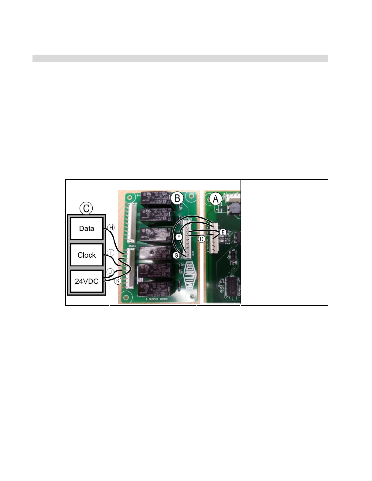
Ecolab HELMS Data Interface
BIPCUI07 (Published) Book specs- Dates: 20160222 / 20160222 / 20160222 Lang: ENG01 Applic: PCU
Ecolab HELMS Data Interface
This document describes how to connect a Milnor CBW tunnel washer to an Ecolab chemical
controller with a HELMS data interface in the field.
1. Requirements
The interface described in this document requires the following software and hardware:
• Mentor controller software must be version 3.2 or later
• tunnel washer processor board software must be 25704 or later
• Milnor 6-output board (part number 08BN6OAT) must be present in the system
2. Wiring
Figure 1: HELMS Interface Wiring
Diagram Legend
A. Milnor processor board
B. Milnor 6-output board
(08BN6OAT)
C. Ecolab controller
D. MTA28-5 and MTA29-5
E. MTA28-4 and MTA29-4
F. MTA28-7 and MTA29-9
G. MTA28-8 and MTA29-10
H. MTA31-9 and DATA
I. MTA31-6 and CLOCK
J. MTA31-5 and 24 VDC
K. MTA31-8 and 24 VDC
.
2.1. Connections Between Milnor Processor Board and 6-output Board
• Connect MTA28-4 on the processor board and MTA29-4 on the output board.
• Connect MTA28-5 on the processor board and MTA29-5 on the output board.
• Connect MTA28-7 on the processor board and MTA29-9 on the output board.
• Connect MTA28-8 on the processor board and MTA29-10 on the output board.
2.2. Connections Between Milnor 6-output Board and Ecolab Controller
• Connect MTA31-9 on the output board and the DATA terminal on the Ecolab controller.
• Connect MTA31-6 on the output board and the CLOCK terminal on the Ecolab controller.
• Connect MTA31-5 on the output board and the 24 volts DC terminal on the Ecolab
controller.
• Connect MTA31-8 on the output board and the 24 volts DC terminal on the Ecolab
controller.
PELLERIN MILNOR CORPORATION
53
Page 60
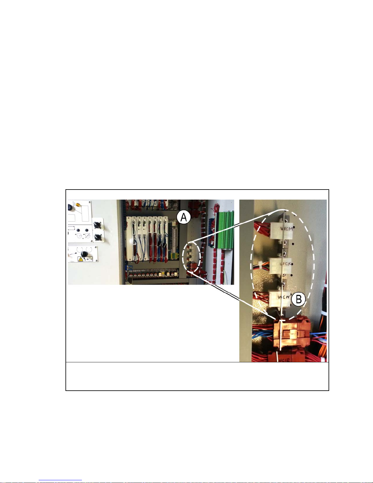
Ecolab HELMS Data Interface
3. Signals
This system requires six signals:
3.1. Run—This signal originates at the Milnor equipment. The source is a control bit programmed
with op code 03. The init code, hold code, and on-time are ignored. This signal is ON when the
tunnel washer is not in a hold condition.
3.2. Transfer—This signal originates at the Milnor equipment. The source is a control bit
programmed with op code 00, init code H, and on-time of 10 seconds. This signal is ON for 10
seconds when the tunnel washer transfers.
3.3. Drop Bag—This signal originates at the Milnor equipment. The source is a relay connected to
the START CONVEYOR output of the tunnel washer. The relay gives the Drop Bag signal to
both the loading system and the Ecolab controller. The START CONVEYOR output is MTA5-4
and MTA5-14 on the board at address 80. These pins are wired to terminals WCH-5 and WCH-6.
Figure 2: Location of WCH-5 and WCH-6
Illustration
A. Right control box on tunnel washer
B. Connector WCH
.
3.4. Clock—This signal originates at the Milnor equipment. The source is pin MTA31-6 on the
Milnor 6-output board. This is the clock pulse used to send data to the Ecolab controller.
3.5. Data—This signal originates at the Milnor equipment. The source is pin MTA31-9 on the
Milnor 6-output board. This is the pulsed data output to the Ecolab controller.
PELLERIN MILNOR CORPORATION
Legend
54
Page 61

Ecolab HELMS Data Interface
3.6. Tunnel to Hold—This signal originates at the Milnor equipment. The source is a control bit
programmed with op code 03. The init code, hold code, and on-time are ignored. This signal is
ON when the tunnel washer is not in a hold condition.
— End of BIPCUI07 —
PELLERIN MILNOR CORPORATION
55
Page 62

How to Use Milnor
®
Electrical Schematic Diagrams
BIUUUK01 (Published) Book specs- Dates: 20130308 / 20130308 / 20130308 Lang: ENG01 Applic: PCR UUU
How to Use Milnor® Electrical Schematic Diagrams
Milnor® electrical schematic manuals contain a table of contents/component list and a set of
schematic drawings. These documents are cross referenced and must be used together.
The table of contents/components list shows, for every component on every schematic in the
manual, the component item number (explained in detail below), statement of function, parent
schematic number, part number, description and electric box location. In older manuals, two
component lists are provided: List 1 sorts the components by function, and List 2 by type of
component. Newer schematic manuals include only the list sorted by component number.
The schematic drawings use symbols for each electromechanical component, and indicate the
function of each. Integrated circuits are not shown, but the function of each microprocessor input
and output is stated. Certain electrical components not pertinent to circuit logic, such as wire
connectors, are not represented on the schematic.
Most machines require several schematics to describe the complete control system and all the
options available on the included models. In most manuals there are some schematic pages that
don't apply to your specific machine because certain options and configurations are mutually
exclusive or are not necessary in all markets. You may find it helpful to mark or remove such
pages. A schematic page that only applies to a subset of machines will normally state, in the title,
which models and/or options it covers. Compare this with the nameplate on your machine and
with your purchase records.
Each schematic is devoted to circuits with common functions (e.g., microprocessor inputs, motor
contactors). Schematics appear in the manual in alphanumeric order.
1. Component Prefix Classifications and Descriptions
Component item numbers consist of up to six characters and appear as part of a component's
symbol on the schematic. The first two characters indicate the general class of component, and
the remaining characters are a mnemonic for the function. For example, “CD” is the code for all
time delay relays, and “SR” stands for safety reset. Thus, CDSR is a time delay relay that serves
as a safety reset.
®
The following are descriptions of electrical components used in Milnor
machines. Descriptions
are in alphabetical order by the component class code (two character prefix).
Note 1: Some component class codes do not have a corresponding symbol, but are represented by a box
and an accompanying note describing the component. Examples of such codes are BA (printed circuit
board), ED (electronic display), and ES (electronic power supply).
BA=Printed Circuit Board—Insulating substrate on which a thin pattern of copper conductors
has been formed to connect discrete electronic components also mounted on the board.
CB=Circuit Breaker (Figure 1)—Automatic switch that opens an electric circuit in abnormal
current conditions (e.g., an overload).
Figure 1: Circuit Breaker (CB)
CD=Control, Time Delay Relay (Figure 2)—A relay whose contacts switch only after a fixed
or adjustable delay, once voltage has been applied to its coil. The contacts switch back to
normal (de-energized state) immediately when the voltage is removed.
PELLERIN MILNOR CORPORATION
56
Page 63
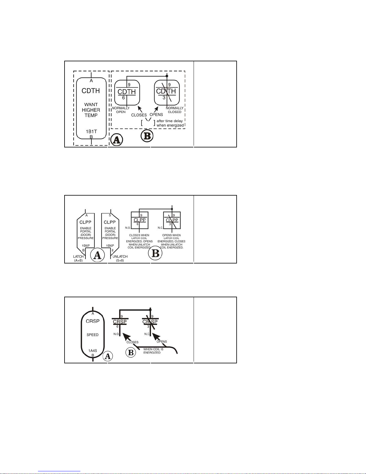
How to Use Milnor
Figure 2: Time Delay Relay (CD)
®
Electrical Schematic Diagrams
Coil and Contacts Legend
A. Coil
B. Contacts
.
CL=Control, Latch Relay (Figure 3)—A relay which latches in an energized or set position
when operated by one coil (the latch/set coil). The relay stays latched even though coil voltage
is removed. The relay releases or unlatches when voltage is applied to a second coil (the
unlatch/reset coil).
Figure 3: Latch Relay (CL)
Coils and Contacts Legend
A. Coils
B. Contacts
.
CR=Control, Relay (Figure 4)—A relay whose contacts switch immediately when voltage is
applied to its coil and revert to normal when the voltage is removed.
Figure 4: Standard Relay (CR)
Coils and Contacts Legend
A. Coil
B. Contacts
.
CP=Control, Photo-Eye (Figure 5)—Photo-eyes sense the presence of an object without direct
physical contact. Photo-eyes consist of a transmitter, receiver, and output module. These
components may be housed in one assembly with the transmitter bouncing light off of a
reflector to the receiver, or these components can be housed in two separate assemblies with
the transmitter pointed directly at the receiver. The photo-eye can be set to turn on its output
either when the light beam becomes blocked (dark operate) or when it becomes un-blocked
(light operate).
PELLERIN MILNOR CORPORATION
57
Page 64
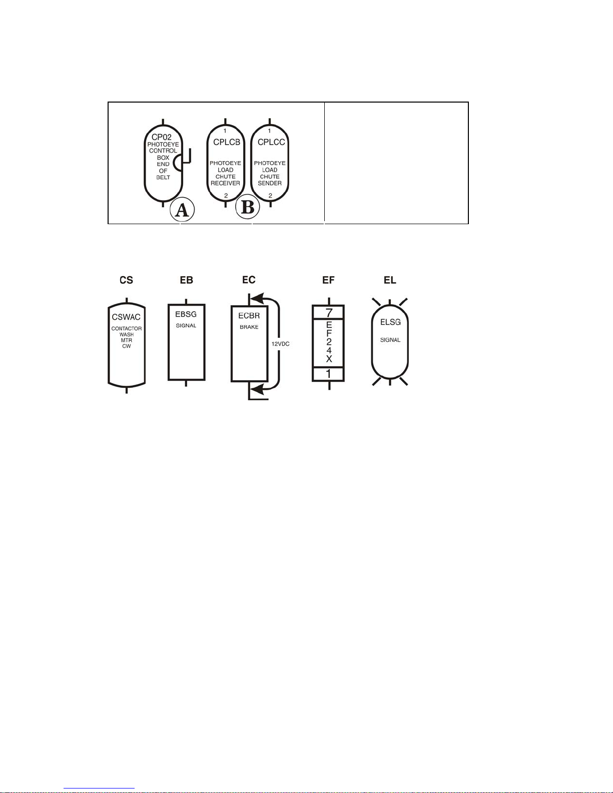
How to Use Milnor
Figure 5: Photo-eye (CP)
Symbols Legend
A. Example of single
assembly
B. Example of two separate
assemblies
®
Electrical Schematic Diagrams
.
CS=Control, Contactor/Motor Starter (Figure 6)—A relay capable of handling heavier
electrical loads, usually a motor.
Figure 6: Other Control Symbols
EB=Electric Buzzer (Figure 6)—An audible signaling device.
EC=Electric Clutch (Figure 6)—A clutch consists of a coil and a rotor. The rotor has two
separate rotating plates. These plates are free to rotate independent of each other until the coil
is energized. Once energized the two plates turn as one.
ED=Electronic Display—A visual presentation of data, such as an LCD (liquid crystal display),
LED (light emitting diode) display, or VFD (vacuum florescent display).
EF=Electric Fuse (Figure 6)—A fuse is an over-current safety device with a circuit opening
fusible member which is heated and severed by the passage of over-current through it.
EL=Electric Light (Figure 6)—Indicator lights may be either incandescent or fluorescent.
EM=Electro Magnet Solenoid—A device consisting of a core surrounded by a wire coil through
which an electric current is passed. While current is flowing, iron is attracted to the core (e.g.,
a pinch tube drain valve solenoid).
ES=Electronic Power Supply—A device that converts AC (alternating current) to filtered and
regulated DC (direct current). The input voltage to the power supply is usually 120 or 240
VAC. The output is +5, +12, and -12 VDC.
ET=Thermal Overload (Figure 7)—A safety device designed to protect a motor. A thermal
overload consists of an overload block, heaters, and an auxiliary contact. The auxiliary contact
is normally installed in a safety (three-wire) circuit that stops power to the motor contactor
coil when a motor overload occurs.
PELLERIN MILNOR CORPORATION
58
Page 65
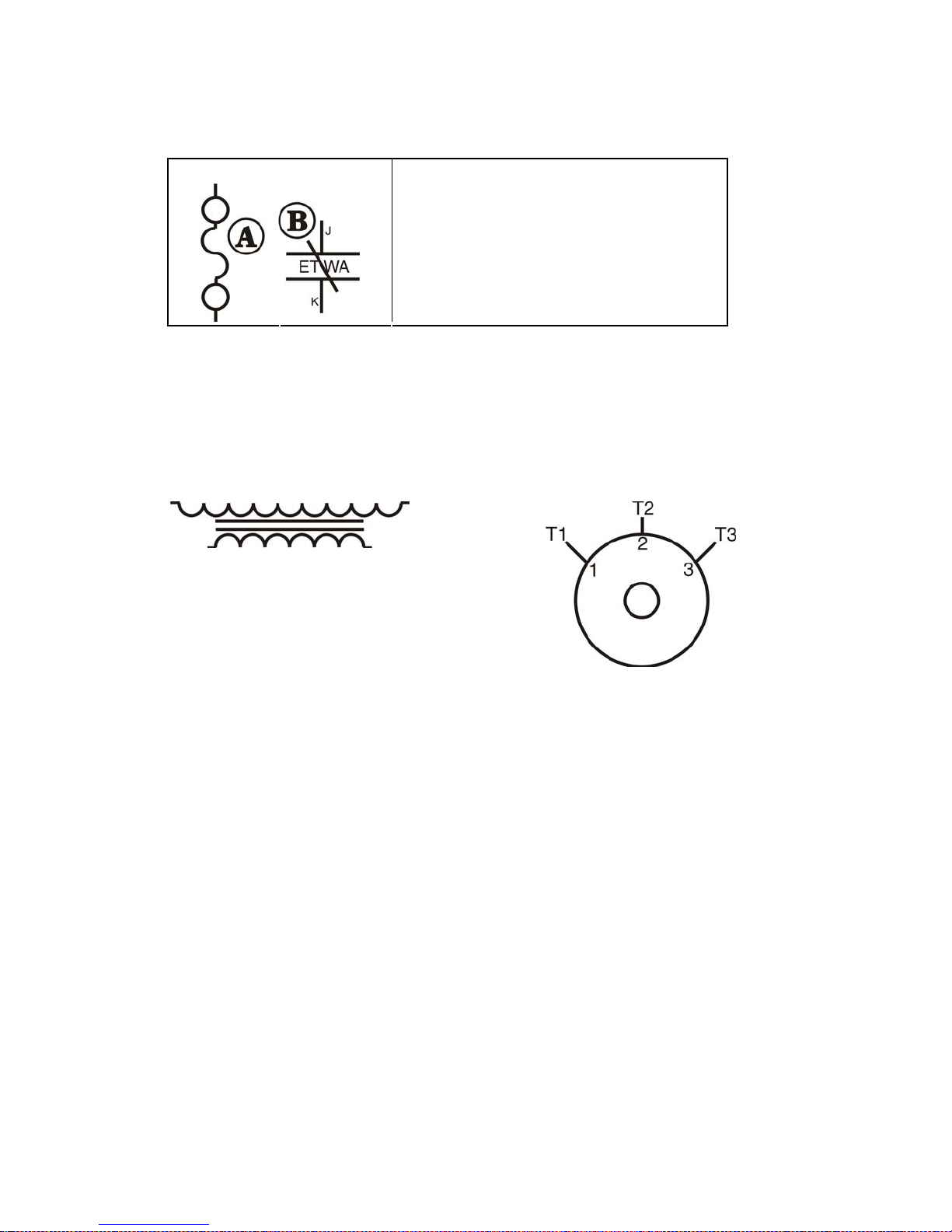
How to Use Milnor
Figure 7: Thermal Overload (ET)
Schematic Symbol Legend
®
Electrical Schematic Diagrams
A. Heater (one per phase)
B. Overload relay; contacts open if overload
condition exists
.
EX=Electrical Transformer (Figure 8)—A device that transfers electrical energy from one
isolated circuit to another, often raising or lowering the voltage in the process.
KB=Keyboard—Device similar to a typewriter for making entries to a computer.
MN=Electronic Monitor (CRT)—A cathode ray tube used for visual presentation of data.
MR=Motors (Figure 9)—Electromechanical device that converts electrical energy into
mechanical energy.
Figure 8: Transformer (EX) Figure 9: Electric Motor (MR)
MV=Motor (Variable Speed) Inverter—To vary the speed of an AC motor, the volts to
frequency ratio must be kept constant. The motor will overheat if this ratio is not maintained.
The motor variable speed inverter converts three phase AC to DC. The inverter then uses this
DC voltage to generate AC at the proper voltage and frequency for the commanded speed.
Note 2: Switch symbols used in the schematics and described below always depict the switch in its unactuated state.
PX=Proximity Switch (Figure 10)—A device which reacts to the proximity of an target without
physical contact or connection. The actuator or target causes a change in the inductance of the
proximity switch which causes the switch to operate. Proximity switches can be two-wire
(AC) or three-wire (DC) devices.
PELLERIN MILNOR CORPORATION
59
Page 66
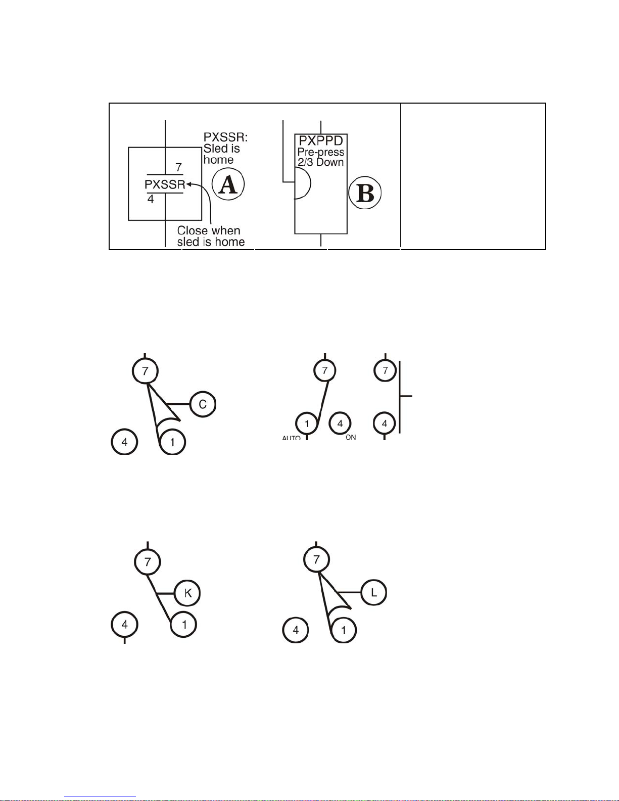
How to Use Milnor
Figure 10: Proximity Switches (PX)
Switch Symbols Legend
A. Alternating current
B. Direct current proximity
®
Electrical Schematic Diagrams
proximity switch
switch
.
SC=Switch, Cam Operated (Figure 11)—A switch in which the electrical contacts are opened
and/or closed by the mechanical action of a cam(s). Applications include 35-50 pound timer
operated machines, Autospot, timer reversing motor assembly, and some balancing systems.
SH=Switch, Hand Operated (Figure 12)—A switch that is manually operated (e.g., Start
button, Master switch, etc.).
Figure 11: Cam Switch (SC) Figure 12: Hand Operated Switch
(SH)
SK=Switch, Key Lock (Figure 13)—A switch that requires a key to operate. This prevents
unauthorized personnel from gaining access to certain functions (e.g., the Program menu).
SL=Switch, Level Operated (Figure 14)—A switch connected to a float that causes the switch
to open and close as the level changes.
Figure 13: Key Switch (SK) Figure 14: Level Switch (SL)
SM=Switch, Mechanically Operated (Figure 15)—A switch that is mechanically operated by a
part of or the motion of the machine (e.g., door closed switch, tilt limit switches, etc.)
SP=Switch, Pressure Operated (Figure 16)—A switch in which a diaphragm presses against a
switch actuator.
PELLERIN MILNOR CORPORATION
60
Page 67
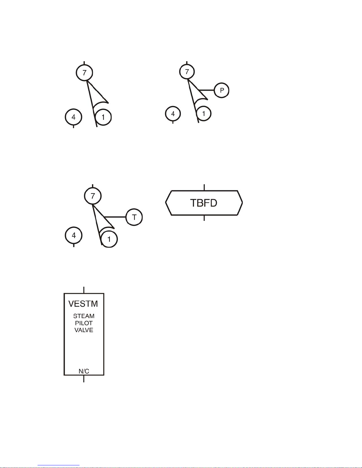
How to Use Milnor
®
Electrical Schematic Diagrams
Figure 15: Mechanical Switch (SM) Figure 16: Pressure Switch (SP)
ST=Switch, Temperature Operated (Figure 17)—A switch that is actuated at a preset
temperature (e.g., dryer safety probes) or has adjustable set points (e.g., Motometers or
Combistats).
TB=Terminal Board (Figure 18)—A strip or block for attaching or terminating wires.
Figure 17: Temperature Switch
(ST)
Figure 18: Terminal Board (TB)
VE=Valve, Electric Operated (Figure 19)—A valve operated by an electric coil to control the
flow of fluid. The fluid can be air, water or hydraulic.
Figure 19: Electrically Operated
Valve (VE)
ZF=Rectifier (Figure 20)—A solid state device that converts alternating current to direct
current.
PELLERIN MILNOR CORPORATION
61
Page 68
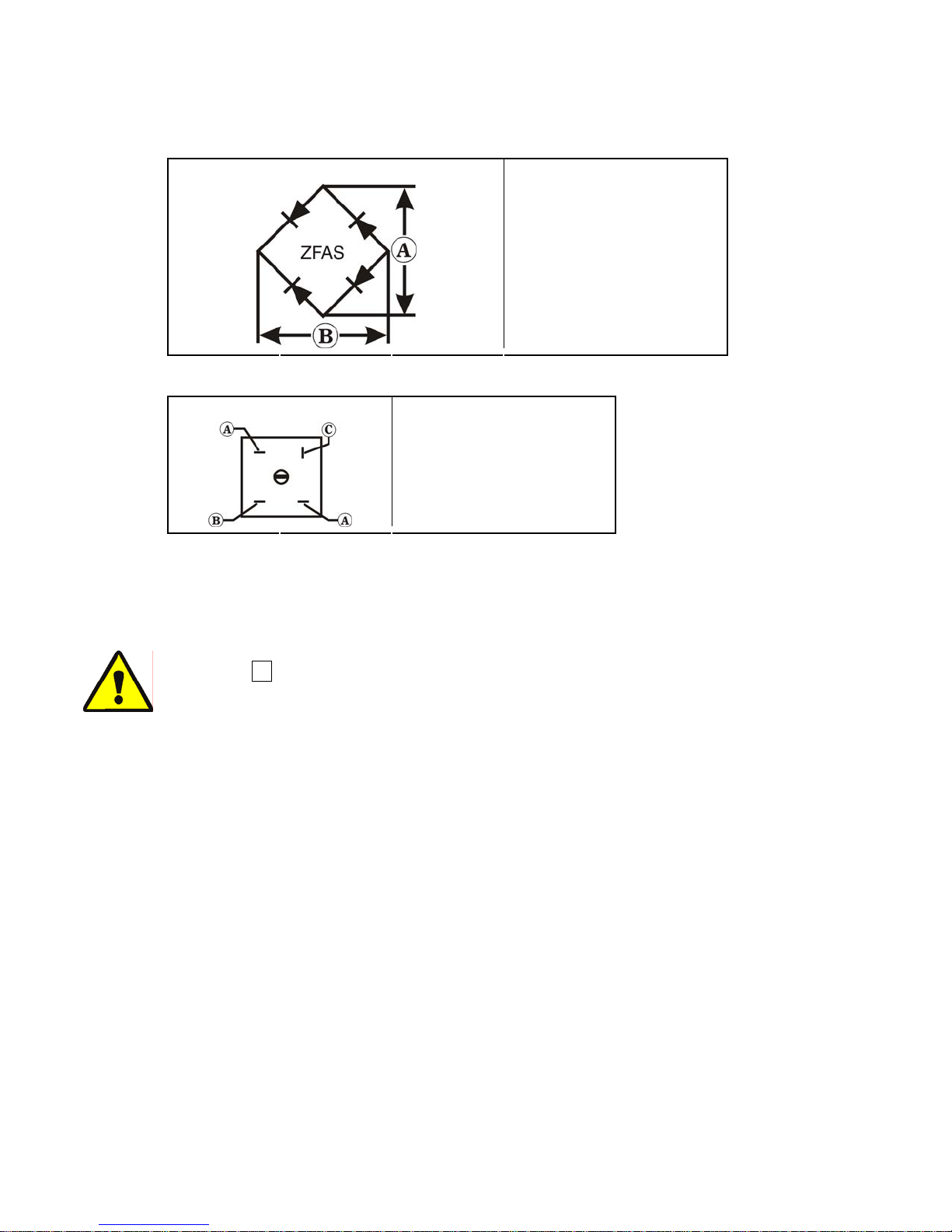
How to Use Milnor
Figure 20: Bridge Rectifier (ZF)
Component Symbol Legend
A. Alternating current input
B. Direct current output
®
Electrical Schematic Diagrams
.
Figure 21: Bridge Rectifier
Component Legend
.
A. Alternating current in
B. Negative direct current
out
C. Positive direct current out
WC=Wiring Connector—A coupling device for joining two cables or connecting a cable to an
electronic circuit or piece of equipment. Connectors are male or female, according to whether
they plug into or receive the mating connector.
2. Component Terminal Numbering
CAUTION 1 : Risk of Mis-wiring—Due to electrical component manufacturing
inconsistencies, the pin numbers imprinted on components such as connectors and relay bases
used on Milnor machines often do not correspond to the pin numbers shown in the schematics.
• Ignore pin numbers imprinted on in-line connectors (e.g., Molex connectors) and relay
bases.
• Use the pin identification illustrations herein to identify pins on these components.
PELLERIN MILNOR CORPORATION
62
Page 69
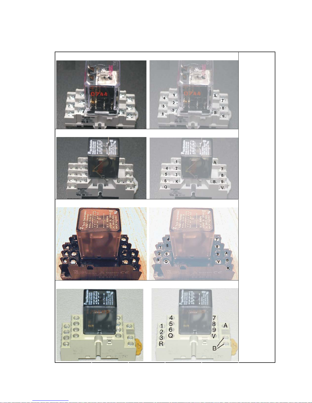
How to Use Milnor
Figure 22: Plug-in Relays
®
Electrical Schematic Diagrams
14-pin Relay with Grey Base (older)
11-pin Relay with Grey Base Legend
Left. View of
relay
and
base
Right. Same
view,
showing pin
numbers
14-pin Relay with Black Base (newer)
14-pin Relay with Beige Base (rare)
.
PELLERIN MILNOR CORPORATION
63
Page 70
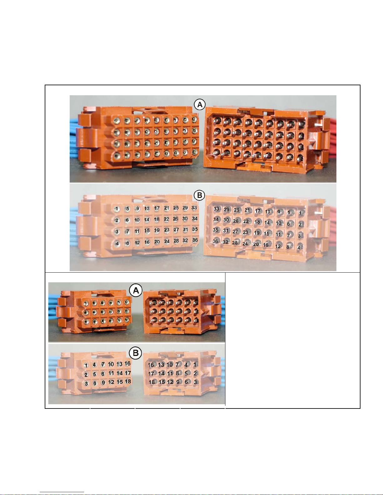
How to Use Milnor
Note 3: Relay functional names ending with the letter "M" (e.g., CRxxM) are not discrete components but
are a component of a printed circuit board. They are usually not individually replaceable.
Figure 23: AMP Connector Pin Locations
36-pin Connector
®
Electrical Schematic Diagrams
18-pin Connector Legend
.
A. View of mating halves of connector
B. Same view, showing assigned pin numbers
PELLERIN MILNOR CORPORATION
64
Page 71
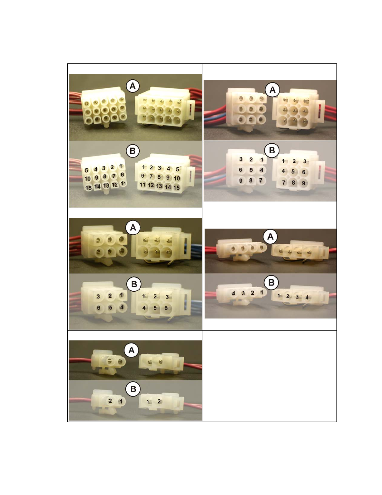
How to Use Milnor
®
Electrical Schematic Diagrams
Figure 24: Molex Connector Pin Locations
15-pin Connector 9-pin Connector
6-pin Connector 4-Pin Connector
2-pin Connector Legend
A. View of mating halves of connector
B. Same view, showing assigned pin numbers
.
PELLERIN MILNOR CORPORATION
65
Page 72
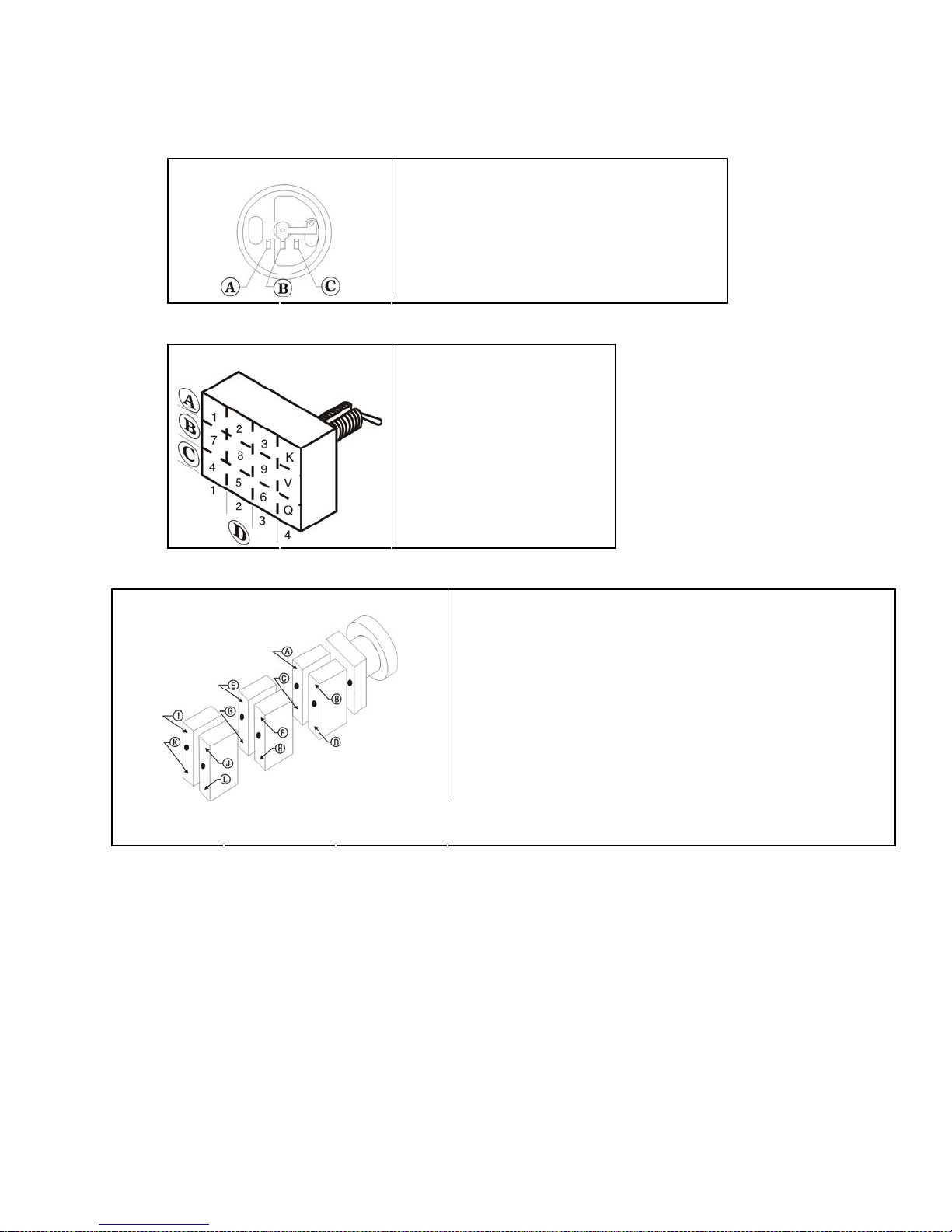
How to Use Milnor
Figure 25: Pressure Switch
Component Legend
A. Contact 1—Normally open
B. Contact 2—Normally closed
C. Contact 3—Common
®
Electrical Schematic Diagrams
.
Figure 26: Toggle Switch
Component Legend
.
Figure 27: Switch with Replaceable Contact Blocks
Rotary or Push-button Switch Component Legend
.
A. Normally closed contacts
B. Common contacts
C. Normally open contacts
D. Pole
A. Terminal 7
B. Terminal 8
C. Terminal 4 if normally open; terminal 1 if normally closed
D. Terminal 5 if normally open; terminal 2 if normally closed
E. Terminal V
F. Terminal 9
G. Terminal Q if normally open; terminal K if normally closed
H. Terminal 6 if normally open; terminal 3 if normally closed
I. Terminal W
J. Terminal X
K. Terminal R if normally open; terminal L if normally closed
L. Terminal S if normally open; terminal M if normally closed
3. Features of Milnor
Document BMP010012 (following this section) is a sample schematic, based on a schematic
diagram for the Milnor
and explanations of the items on the schematic are shown black.
The item numbers below correspond to the circled item numbers shown on the drawing.
1. The first six characters of the drawing number (W6DRYG) indicate that this is a wiring
diagram (W), identify the generation of controls (6), and identify the type of machine
(DRYG=Gas Dryer). These characters appear in the drawing number of every schematic in
the set.
The characters following the first six are unique to each drawing. The two characters
identified as the page number are an abbreviation for the function performed by the depicted
PELLERIN MILNOR CORPORATION
®
Electrical Schematic Diagrams
®
gas dryer. For the purposes of this exercise, the schematic is shown gray
66
Page 73

How to Use Milnor
®
Electrical Schematic Diagrams
circuitry (S+=three-wire circuit) and establish the order in which the schematic occurs in the
manual (schematics are arranged in alpha-numeric order in the manual).
Whenever circuitry changes are significant enough to warrant publishing a new schematic
drawing, the new drawing number will be the same as the old except for the major revision
letter (A in the example).
2. Included in the drawing title are the class of control system, the title of this circuit, and the
circuit voltage.
3. Line numbers are provided along the bottom edge of the drawing. These permit service
®
personnel in the field and at the Milnor
factory to quickly relate circuit locations when
discussing troubleshooting over the phone. Page and line numbers are referenced on the
drawing as explained in items five and six below.
4. Relay contacts show the page and line number on which the relay coil may be found. This is
the type of cross referencing most frequently used in troubleshooting.
5. Relay coils show the page and line number on which its associated contacts are located.
6. Relay contacts and relay coils show the physical location of the relay.
7. The designation MTA applies to electronic circuit board connections. Typically, a control
system will contain several different types of circuit boards and one or more boards of each
type. A numerical suffix identifies the board type and a numerical prefix identifies which one
of several boards of a given type is being depicted. For example, the designation 1MTA5
identifies this as the first I/O board (8 output, 16 input board) in the control system. As shown
on the drawing, a pin number follows the board number, separated by a dash. Thus, 1MTA59 is pin 9 on this board. The numerical designations for board types vary from one control
system to another. Some of the board types commonly encountered on the Mark V and Mark
VI washer-extractor control and their designations are as follows:
• MTM1-MTM8 = Mother board
• MTA1-MTA5 = 8 output, 16 input (8/16) boards
• MTA11-MTA14 = 24 output boards
• MTA30-MTA40 = processor boards
• MTA41-MTA43 = digital to analog (D/A) boards
• MTA51-MTA55 = analog to digital (A/D) boards
• MTA81-MTA85 = balance A-D board
The complete listing of the boards utilized in a given control system can be found in the
component list for that system.
8. Wire numbers, as described earlier in this section, are shown at appropriate locations on the
schematic drawing.
9. Where diamond symbols appear at the end of a conductor, these are match points for
continuing the schematic on another drawing. The page and line number that continues the
circuit is printed adjacent to the diamond symbol. Where more than one match point appears
on the referenced page, match diamonds containing corresponding letters.
PELLERIN MILNOR CORPORATION
— End of BIUUUK01 —
67
Page 74
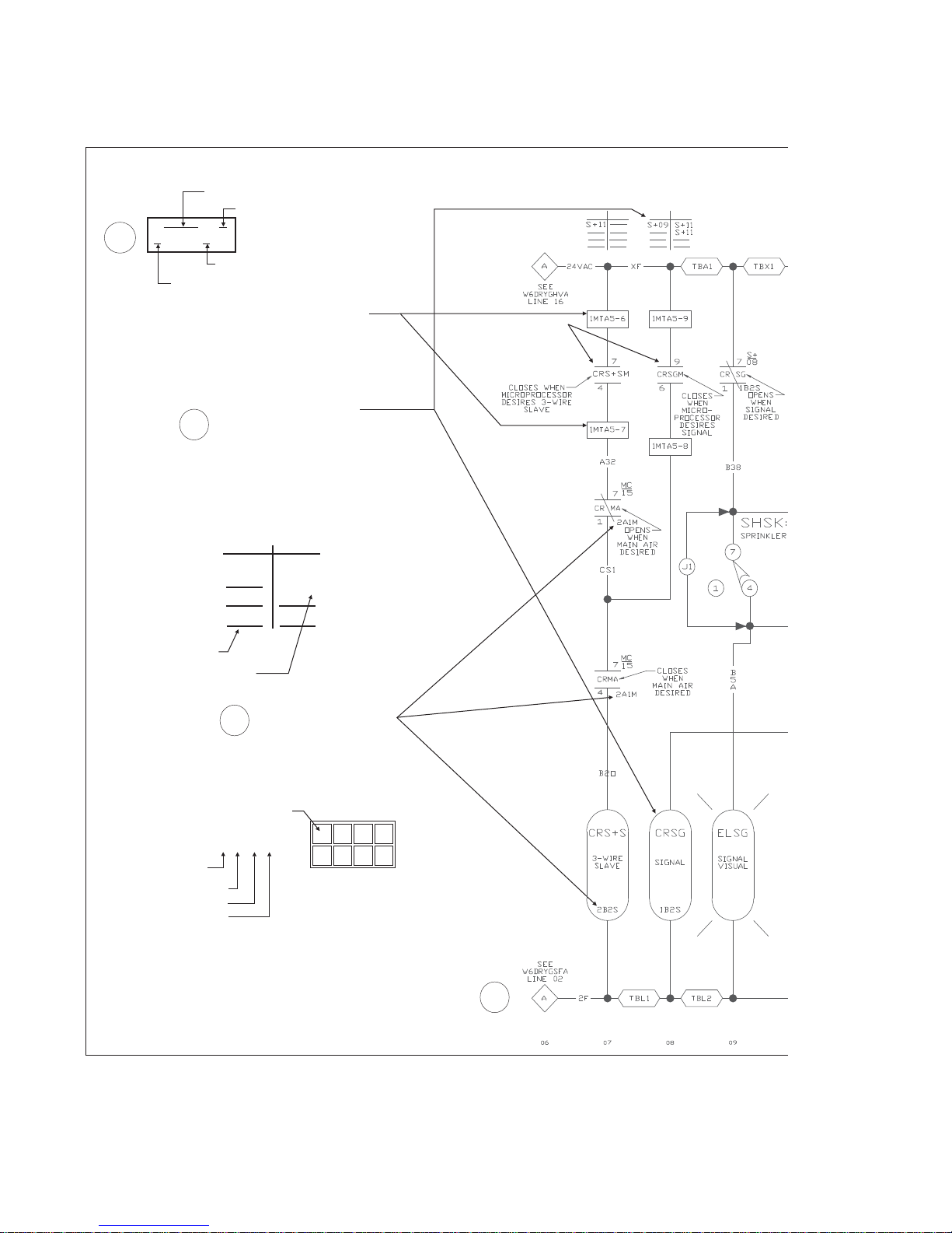
7
Mass termination assembly
Pin number
1MTA5-6
MTA designation on board
Board MTA group designation
An MTA is a connection on an
electronic circuit board. The
notes and the tag page locate
the appropriate board.
This indicates on which
schematic page and
5
line number the relay
contacts of this coil (on Line
08) are located (i.e.,
W6DRYGS+, Lines 9 and 11).
Normally
closed
contacts
7-1 contact
8-2 contact
9-3 contact
V-K contact
Contact not used
Drawing and line where
contact is located
S+09 S+11
6
Normally
open
contacts
7-4 contact
8-5 contact
S+11
9-6 contact
V-Q contact
This is the physical
location of the relay on
the machine. Row and
column numbers are
shown on the appropriate
tag for each relay tray.
Any relay that ends
with an "M" is
located on an
electronic board.
Position
2A1M
Relay Tray
Number
Row
Column
Function
(M=Main Air)
BMP010012 (left) / 2018343
123 4
A
B
9
68
Page 75
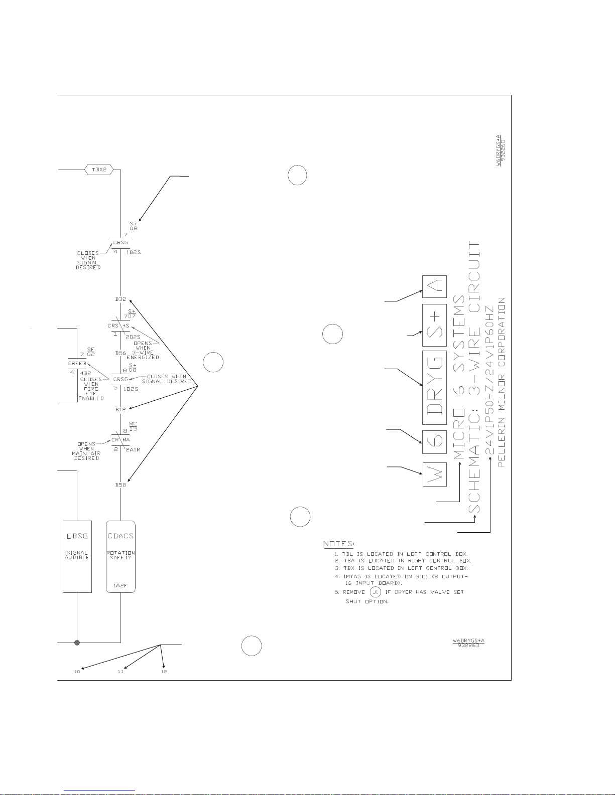
This indicates on which
page (W6DRYGS+) and
line number (08) the relay
coil can be found for this
set of contacts
4
Major revision
(letter)
Page number
1
(S+)
8
Wire identification marking.
This designation is
stamped on the wire every
6 inches and is used with
the signal routing table.
Page line
numbers
3
Machine type
(Gas fired dryer)
6th generation
of controls
Class of control system
2
W = Wiring
Title of this circuit
Voltage of this circuit
BMP010012 (right) / 2018343
69
Page 76
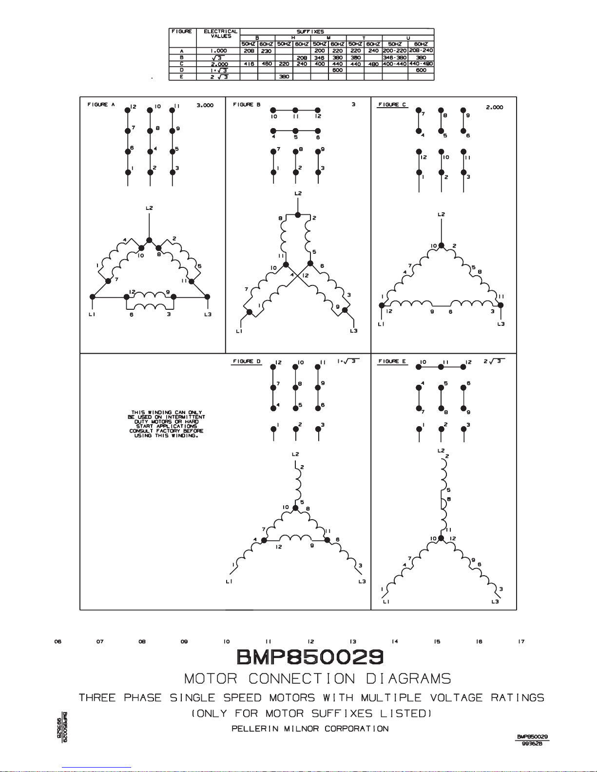
70
Page 77
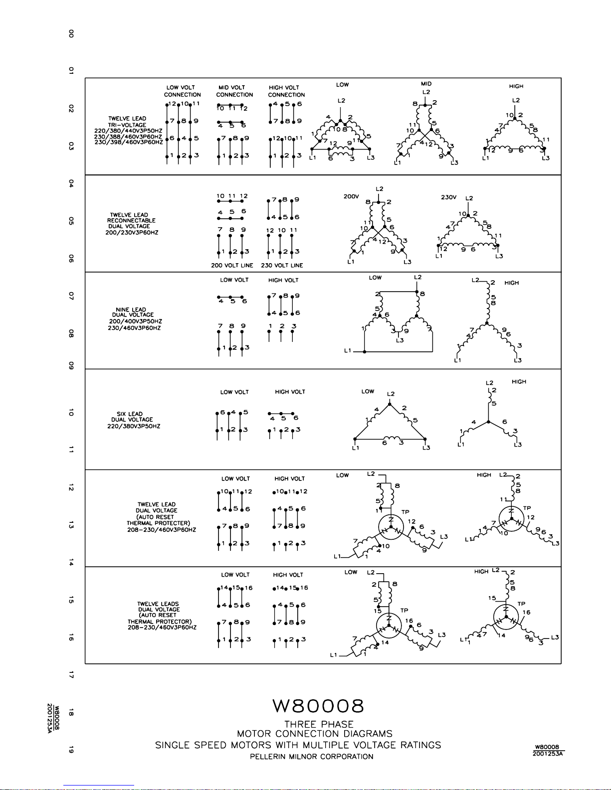
71
Page 78
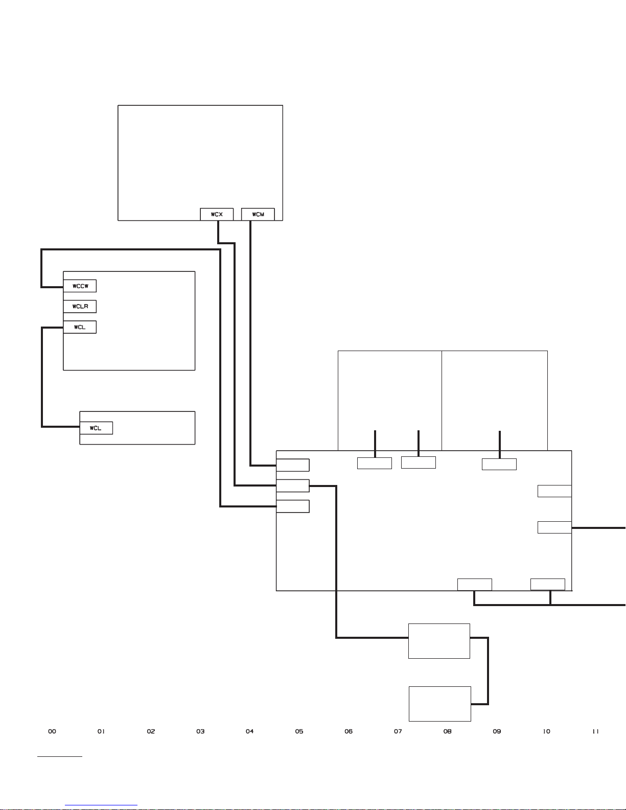
CONLO OR
CONWA
BOX
MENTOR
CONWA
LIGHTS
WCM
WCX
WCCW
INTERPRET
RELAY BOX
WCJI
WCJR
MAIN CONTROL BOX
PROXIMITY SWITCHES
C.W.
C.C.W.
PROXIMITY SWITCHES
FLUSH
INTERFACE BOX
WCJ
CUSTOMER
CONNECTIONS
ASSIGNABLE
OUTPUTS
WCA*
WCH
WCT*
ASSIGNABLE
INPUTS
WCB*
W9CBW3CC
99133B
72
TRANSFER
SAFETY
Page 79
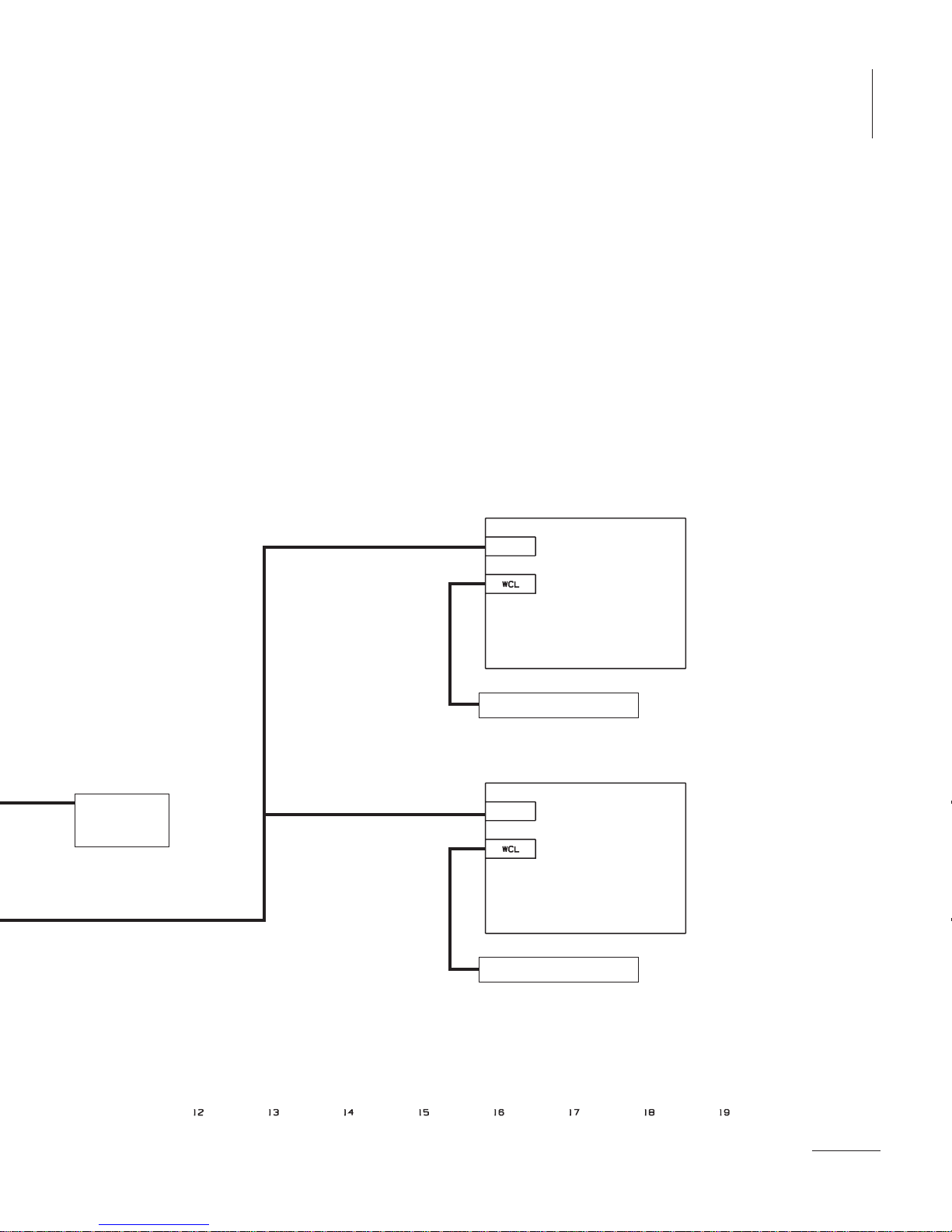
MAIN CONTROL BOX
WCA* OUTPUTS
WCB* INPUTS
WCT* TEMPERATURE PROBES
WCM MENTOR
WCX FEED THRU FOR PROX SW.
WCH CUSTOMER CONNECTIONS
WCCW CONLO/CONWA CONNECTIONS
WCJ FLUSH INTERFACE BOX
WCIR INTERPRET RELAYS I1-I16
WCJR INTERPRET RELAYS J1-J16
MENTOR
WCX PROXIMITY SWITCHES
WCM MENTOR
WASH ZONE AND RINSE ZONE
WCW CONNECTIONS FOR WASH ZONE INTERFACE
WCL LEVEL SWITCHES
99133B
W9CBW3CC
EACH
TEMPERATURE
PROBE
WCW
RINSE ZONE BOX
LEVEL SWITCHES
WCW
WASH ZONE BOX
LEVEL SWITCHES
W9CBW3CC
PELLERIN MILNOR CORPORATION
G3 CBW SYSTEM MARK 9
SCHEMATIC: CABLE ROUTINGS
W9CBW3CC
99133B
73
Page 80
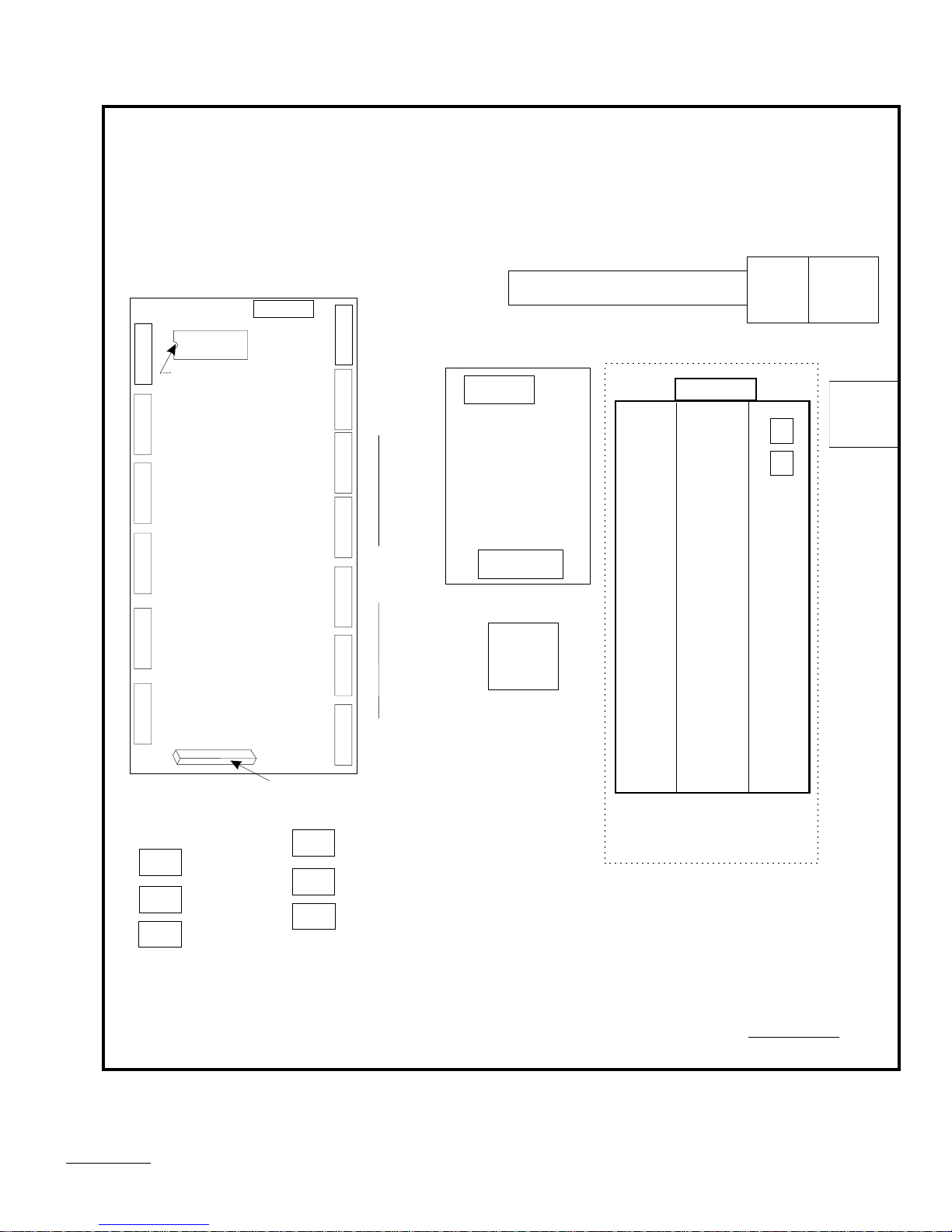
NOTES FOR INSTALLING EPROM:
1.EPROMS MUST BE INSTALLED IN THE CORRECT
SOCKET FOR THE MACHINE TO OPERATE. FOR THIS
MACHINE THERE WILL BE ONE EPROM AND IT MUST BE
INSTALLED IN THE SOCKET LABELED IC2.
2. MAKE SURE THAT ALL PINS ARE IN THEIR HOLES WHEN
INSERTING (BE CAREFUL NOT TO BEND PINS UNDER
CHIP.)
IC2
EPROM
1 10
1MTA35
MUST BE
INSTALLED
WITH NOTCH
IN POSITION
SHOWN.
1 10
BPB 186
1MTA40
PROCESSOR BOARD
1 10
(NOT USED) KEYPAD
1MTA37
1 10
DISPLAY
1MTA36
1 6
1MTA38
INPUTS
1 8
1MTA39
WCY
WCM
WCX
OUTPUTS
1MTA28
18
W1
EDGE CARD
CONNECTOR
WCP
WCR
WCC
10 16 16 1
6 1
6 16 1
10 1
1MTA31
2MTA31
1MTA32
#2
1MTA33
#3
1MTA341MTA29
/#5
1MTA30
POWER
1MTP
BATT.
ESPS
#1
MENTOR POWER
SUPPLY
120VAC TO
+12VDC,
-12VDC,5VDC
1MTD
RS485
#4
RS232
CBW SYSTEMS
CRPR
TBM
BLANK
OPTIONAL
0MTA1
BLANK
CRTP+
SW1 SW2
ADDRESS
0
2
FOR CONWA LOAD CELL
A TO D CONVERTER BOARD #0
CRHNS
WCWA
W9CBW3TG1
2009173B
MENTOR CONTROL PANEL
PELLERIN MILNOR CORPORATION
74
B2TAG99014
2009173A
Page 81
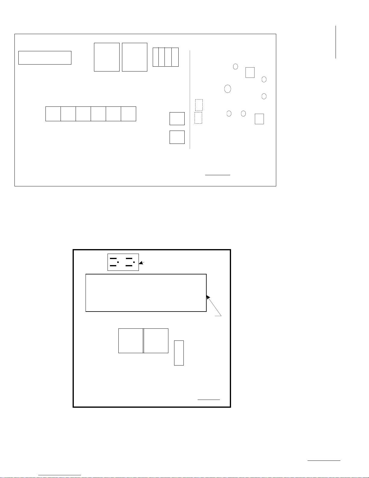
TBF
CRCBF
CRSBF
CSMPF
CRRD
CBMPF
CRFECRFLLCRFLK
G3 CBW SYSTEM MARK 9
FLUSH TANK INTERFACE BOX
PELLERIN MILNOR CORPORATION
2009173B
GND
A3 L3
A2 L2
A1 L1
SHDTF
VEF1
VEFT
SHFLT
B2TAG99011
__________
120V AC
99247G
CB03
ELPFN
DOOR
_____
ELVF1
SHFI
ELFT
ELRD
ELPF
SHPF
W9CBW3TG1
GROUND FAULT OUTLET
110/120VAC-20AMP
MENTOR UNINTERRUPTED POWER SUPPLY
ONLY OUTLETS
WITH BLACK BACK-
GROUND AROUND
CSMP+ CSTP+
MILTRON
POWER
ENABLED
TUNNEL
POWER
ENABLED
THEM ARE BATTERY
GND
CBW SYSTEM
MENTOR POWER
ENABLE PANEL
PELLERIN MILNOR CORPORATION
BACKED UP
B2TAG99013
99163G
W9CBW3TG1
CONTROL BOX LAYOUTS
G3 CBW SYSTEM MARK 9
PELLERIN MILNOR CORPORATION
FOR MENTOR, AND FLUSH INTERFACE BOX
75
W9CBW3TG1
2009173B
Page 82
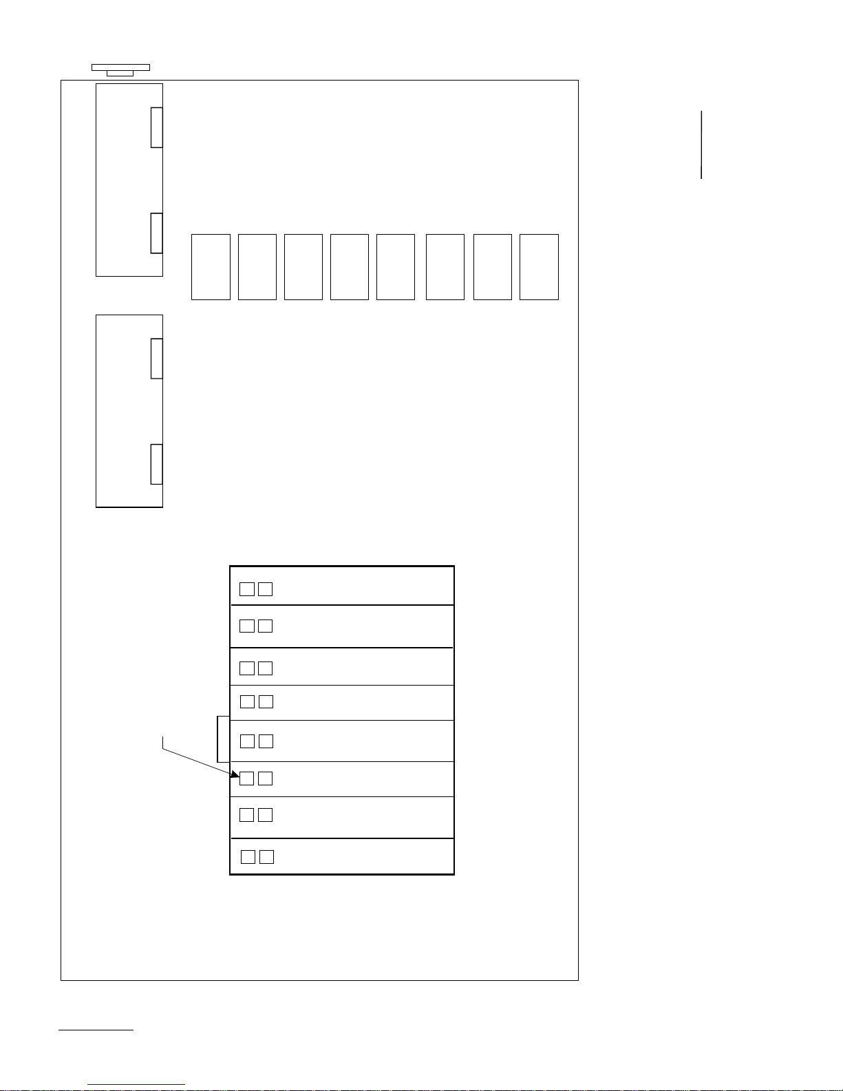
E-STOP
SHED2
BAS-1
SNUBBER
BOARD #1
1MTA31
1MTA32
INPUTS FOR
1ST 8/16 BOARD
INPUTS FOR
2ND 8/16 BOARD
INPUTS FOR
3RD 8/16 BOARD
ANALOG INPUTS FOR
2009173A
B2TAG99017
TEMP. MOD 1 THRU 8
ANALOG INPUTS FOR
TEMP MOD 9 THRU 16
OUTPUTS FOR
1ST 8/16 BOARD/
24 OUTPUT
OUTPUTS FOR
2ND 8/18 BOARD/
24 OUTPUT
OUTPUTS FOR
3RD 8/16 BOARD/
24 OUTPUT
AS REQUIRED FOR
BOARDS ARE ADDED
ADDITIONAL SNUBBER
BAS-*
SNUBBER
BOARD #*
*MTA31
ADDITIONAL OUTPUTS
*MTA32
X REPRESENTS
NEXT AVAILABLE
ADDRESS FOR A
WCB-1
24 OUTPUT BOARD
SW1 SW2
1
ADDRESS
SW1 SW2
2
ADDRESS
SW1 SW2
3
ADDRESS
SW1 SW2
1
ADDRESS
SW1 SW2
2
1MTA1
ADDRESS
SW1 SW2
X
ADDRESS
SW1 SW2
0
ADDRESS
SW1 SW2
0
ADDRESS
WCB-2
0
0
0
2
2
1
1
A
WCB-3
BIO1 (8 OUTPUT/16INPUT BOARD #1)
BIO-2 (8OUTPUT/16INPUT BOARD #2)
BIO-3 (8OUTPUT/16INPUT BOARD #3)
A TO D CONVERTOR
FOR TEMPERATURE MODULES 1 THRU 8
A TO D CONVERTOR
FOR TEMPERATURE MODULES 8 THRU 16
BO24-1 ( 24 OUTPUT BOARD #X)
BO24-0 ( 24 OUTPUT BOARD #0)
FOR FOR ALLIED INTERFACE
A TO D CONVERTOR
FOR OVERHEAD FILL TANKS
WCT-1
WCT-2
WCA-1
WCA-2
NOTE: THE BOARDS SHOWN IN THIS CARD CAGE
ARE FOR A TYPICAL CBW SYSTEM. ONLY THE
BOARDS REQUIRED FOR OPTIONS ON THIS
PARTICULAR SYSTEM WILL BE INCLUDED.
WCA-3
G3 CBW SYSTEM MARK 9
MAIN CONTROL BOX
PELLERIN MILNOR CORPORATION
RIGHT (MODULE) SECTION
W9CBW3TG2
2009173B
76
Page 83
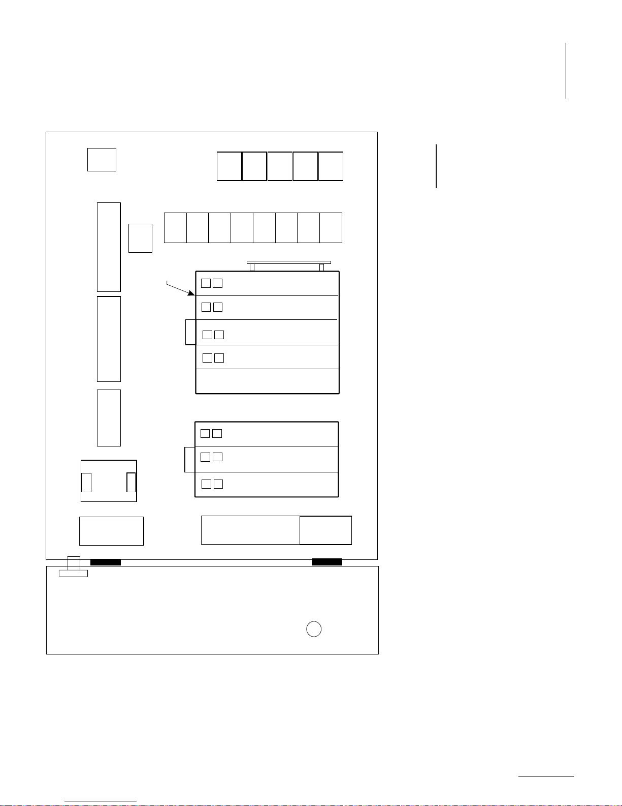
WCIR
WCM
WCX
WCH
WCCW
WCJ
2009173A
B2TAG99018
2009173B
W9CBW3TG2
TBE
STANDARD OUTPUTS
FEED TO
MENTOR
TBB
120V POWER
TBP
TO MENTOR
SERIAL LINK
CONNECTION
1MTP
POWER
ESPS2
SUPPLY
PS24
WCAB
1MTD
SW 1 FOR THESE
2 OPTIONAL
OUTPUT BOARDS
MUST BE THE 0
AND 1 IF PRESENT.
CRAB
FOR REMOTE
DATA ENTRY
CRNS8
AMTA1
SW1 SW2
IMTA1
SW1 SW2
0
0
ADDRESS
SW1 SW2
0
8
ADDRESS
SW1 SW2
1
1
ADDRESS
SW1 SW2
X
1
ADDRESS
1
3
ADDRESS
SW1 SW2
1
2
ADDRESS
SW1 SW2
1
1
ADDRESS
CRST2
CRST1
SNUBBER BOARD
BIO-A (8 OUTPUT-16 INPUT BOARD)
BIO-B (8 OUTPUT-16 INPUT BOARD)
BO24-1 (24OUTPUT BOARD 1)
(OPTIONAL FOR INTERPRET RELAYS)
BO24-1 (24OUTPUT BOARD X)
(OPTIONAL FOR 32 INTERPRET RELAYS)
BLANK
BO24-3 (24OUTPUT BOARD 3)
BO24-2 (24OUTPUT BOARD 2)
BO24-1 (24OUTPUT BOARD 1)
CRLCB
BAS-A
CRHN
CUSTOMER CONNECTIONS
TBC
CRUN8
CRCBS
GROUND
G3 CBW SYSTEM MARK 9
MAIN CONTROL BOX
LEFT (STD. OUTPUT) SECTION
W9CBW3TG2
CONTROL BOX LAYOUTS
G3 CBW SYSTEM MARK 9
PELLERIN MILNOR CORPORATION
FOR MAIN CONTROL BOX
E-STOP
SHED3
77
CIRCUIT
BREAKER
EB02
W9CBW3TG2
2009173B
Page 84
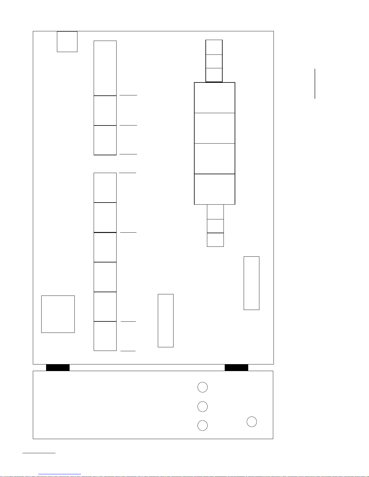
WCIR
TBD
FLOW
FOR
CRRDA CRFD
CRLD2CRWDT
FOR LONG
CRLD1CREST
TANK
SPLIT
TANK
DRAIN
DISTANCE
INCOMPATIBILITY
DRAIN
L3
L2
PUMP MOTOR
L1
4
ETBM
3
ETBM
2
ETBM
1
ETBM
T3
POWER FROM
INVERTER
2009173A
B2TAG99009
CDWDT
CRCBCRMF
STANDARD DRIVE RELAYS
FLOW
ENABLED
LOGIC CONNECTIONS
TO INVERTER
CONTROL BOX
TBI
SHEST
T1 T2
DRIVE MOTOR
POWER FROM
INVERTER
GROUND
G3 CBW SYSTEM MARK 9
MAIN CONTROL BOX
PELLERIN MILNOR CORPORATION
MIDDLE (DRIVE) SECTION
W9CBW3TG3
2009173B
78
SHO1
SKEST
CB37
Page 85
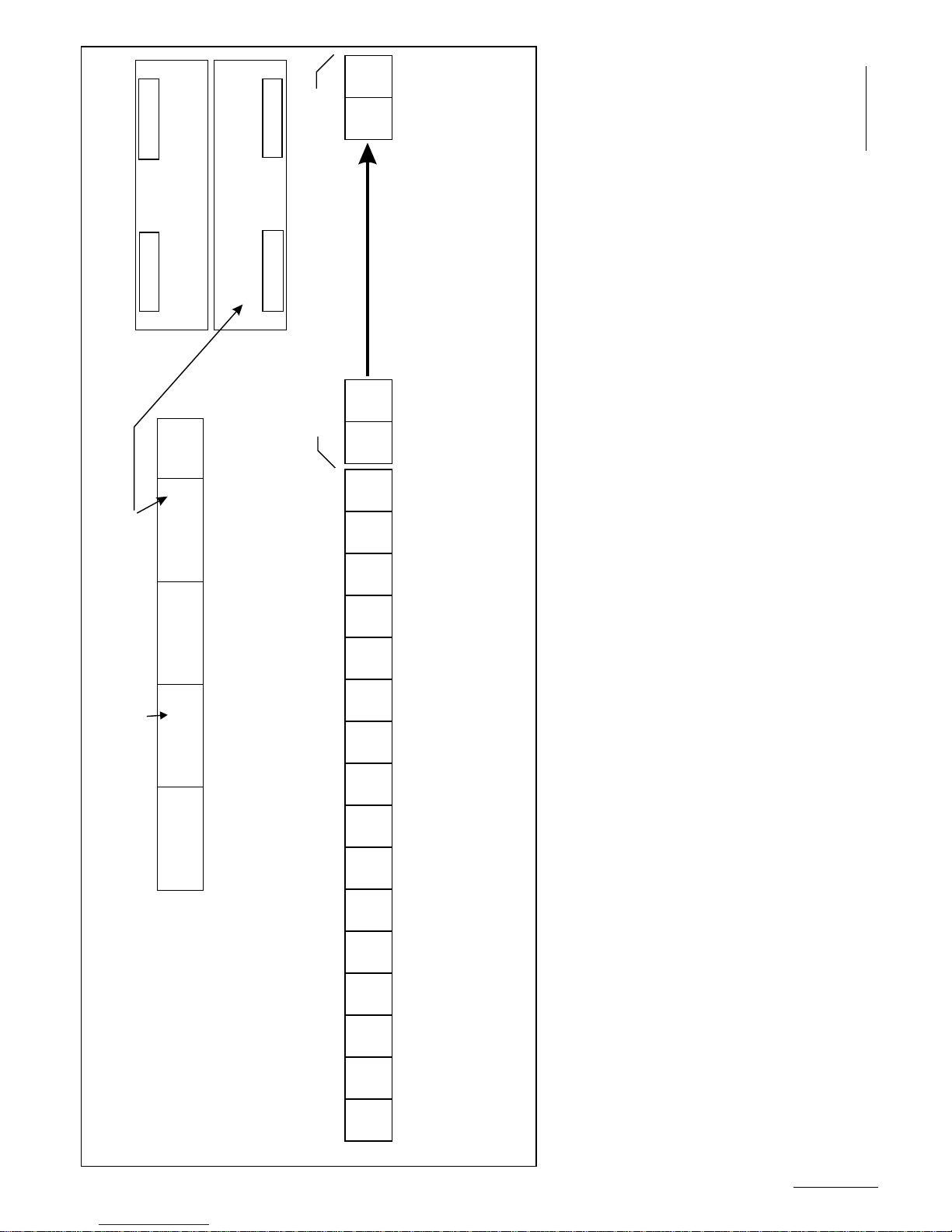
CRJ16
*MTA32
*MTA31
SNUBBER
GND
CONNECTS
SNUBBER
TO PIN 4
OF RELAYS
*MTA31
*MTA32
J1 THRU J16
CRJ15
2006332G
B2TAG99012
___________
2009173B
W9CBW3TG3
INCLUDED FOR 32 INTERPRET RELAYS ONLY
CRI16 CRJ2
CRI15 CRJ11
CRI14
CRI13
TO PIN 4
OF RELAYS
CONNECTS
I1 THRU I16
CRI12
CRI11
W9CBW3TG3
PELLERIN MILNOR CORPORATION
TO PIN 7
OF RELAYS
CONNECTS
INCLUDED FOR 32 INTERPRET RELAYS ONLY
TB2 TB4 TB3 TB5
CONNECTS
J1 THRU J16
TO PIN 7
OF RELAYS
I1 THRU I16
CRI10
CRI9
CRI8
CRI7
CRI5 CRI6
CRI4
CRI3
G3 CBW SYSTEM MARK 9
INTERPRET RELAY BOX
CONTROL BOX LAYOUTS
G3 CBW SYSTEM MARK 9
PELLERIN MILNOR CORPORATION
FOR MAIN CONTROL AND INTERPRET RELAY BOX
CRI2
CRI1
79
W9CBW3TG3
2009173B
Page 86
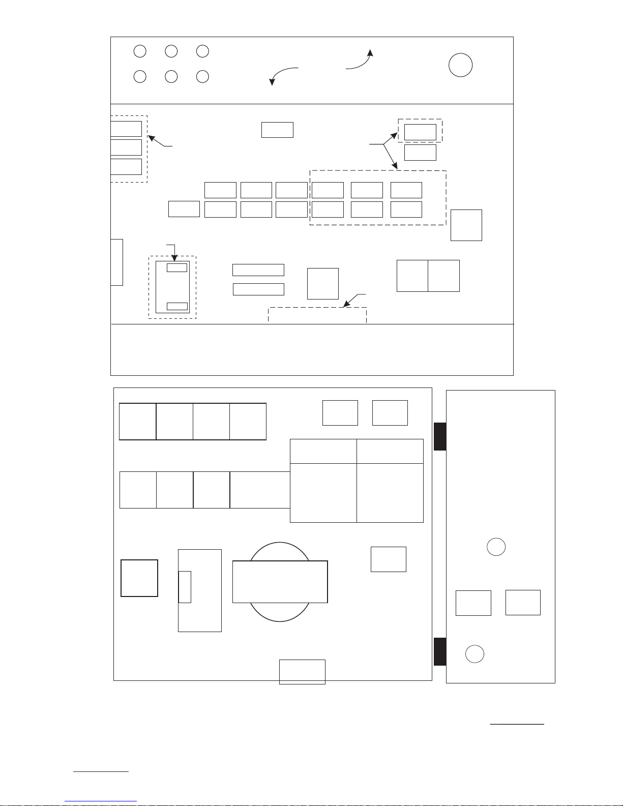
W9CBW3TG4
2014385B
G3 CBW SYSTEM MARK 9
HOLDING TANK
PELLERIN MILNOR CORPORATION
B2T2003025
2008083G
SHEF
ELPS
EF24
SHP
VEFT
CD1
CDHL
CRNIH
WCO
WC1
GND
SPHZR
CRPS
CRFT
CRHA1 CR24 TBD
ETPUP
CSPUP
ETPUQ
CSPUQ
EX24
MTA1
CBMC
CSCF CSCR
GND
WCL
WCLR
CONWAY
ONLY
TOP OF BOX
CONWAY
ONLY
OPTIONAL
OPTIONAL
WCCW
CRUN1CRWTCRCWH
CRUN2CRCW0CRCWL
CRCBL
CRUN3CR01CD02
ZSCW2
SBO
ZSCW1
CRSCCLSCCRSCA
TBC
TBP
BSM-1
C
B
L
C
SHCMA
ELCP+
SHCMO
ELCFA
SHFR
SHMD
SHCME
PSCL
CONWA/CONLO CONTROLBOX
PELLERIN MILNOR CORPORATION
CBW SYSTEMS MARK 8/9
B2TAG92059
2014385A
__________
MTP1
MTP2
80
Page 87
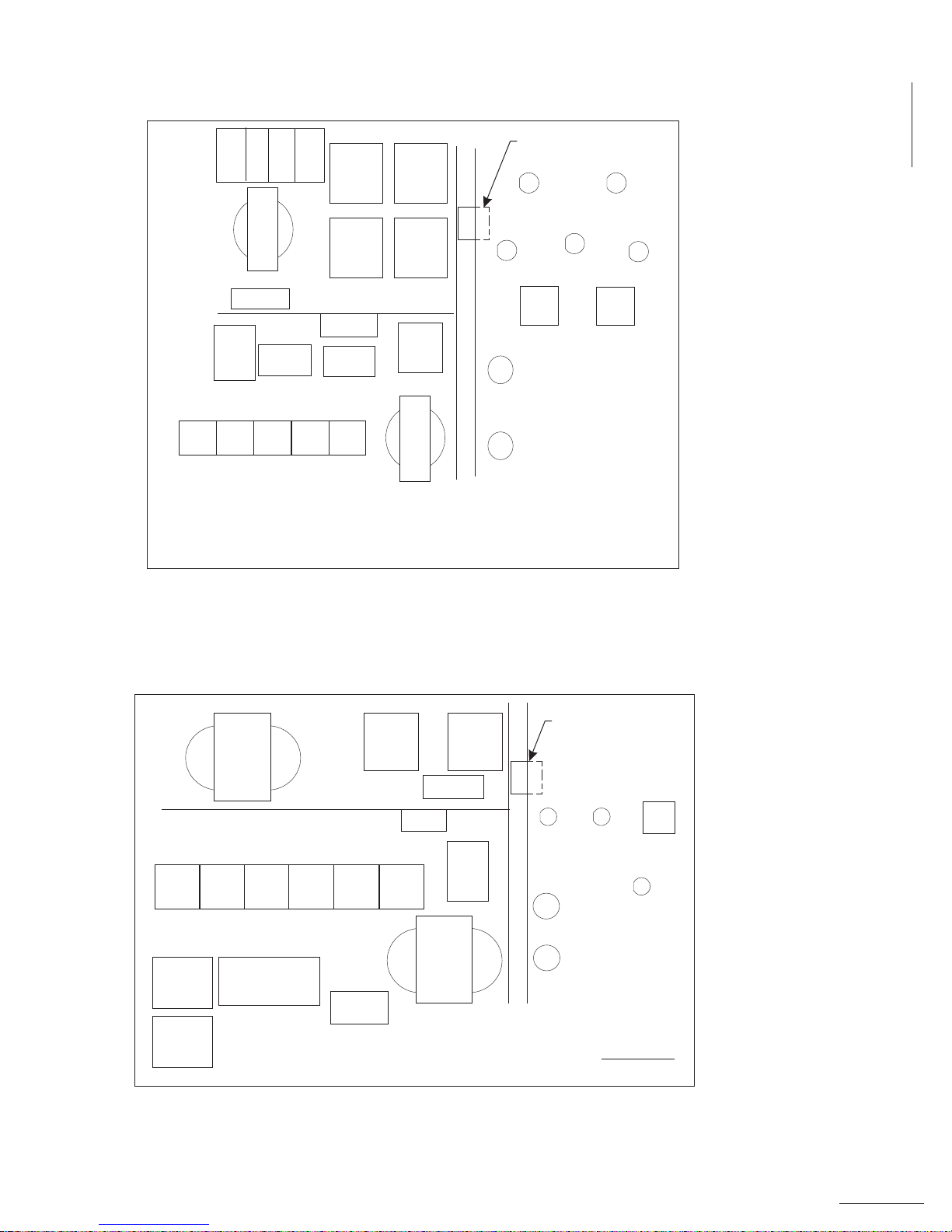
W9CBW3TG4
G3 CBW SYSTEM MARK 9
CONTROL BOX LAYOUTS
FOR RINSE ZONE, WASH WATER FLOW LIFTER, AND CONWA/CONLO
PELLERIN MILNOR CORPORATION
W9CBW3TG4
2014385B
W9CBW3TG4
2014385B
CBWZ1
120V AC
CBWZ2
24V AC
CBWZP
CBWZR
CSWZR
CSWZP
EXPRZ
GND
L1A1L2
A2
L3
A3
GND
DOOR
_____
B2TAG91057
__________
2008224G
WCW
VEWZP
TBR1
TBR24
GND
XFMR
CRNSACRCB2CRLFSCRCB1 CRHFF
MARK 8 CBW MODULE
PELLERIN MILNOR CORPORATION
RINSE ZONE BOX
SHPRS
SHPWZ
ELPRS
ELPRT
ELPWT
ELPWZ
ELFD
VEWZR
OPTIONAL FOR
3HP S/S PUMP
CRHLCDINCR37 CR24CRP CRFD
VEWFS
VEWFSS
VE2W
TBW1
WCL
CBWZR CSWFS
GND
WCW
GND
E
X
P
W
Z
X
F
M
R
B2TAG91058
2008224G
WASH WATER FLOW LIFTER
MARK 8 CBW MODULE
PELLERIN MILNOR CORPORATION
CBFC1
CBFC2
120V AC
24V AC
ELNFT
ELNFS
SHWFS
ELFD
DOOR
OPTIONAL FOR
3HP S/S PUMP
81
Page 88
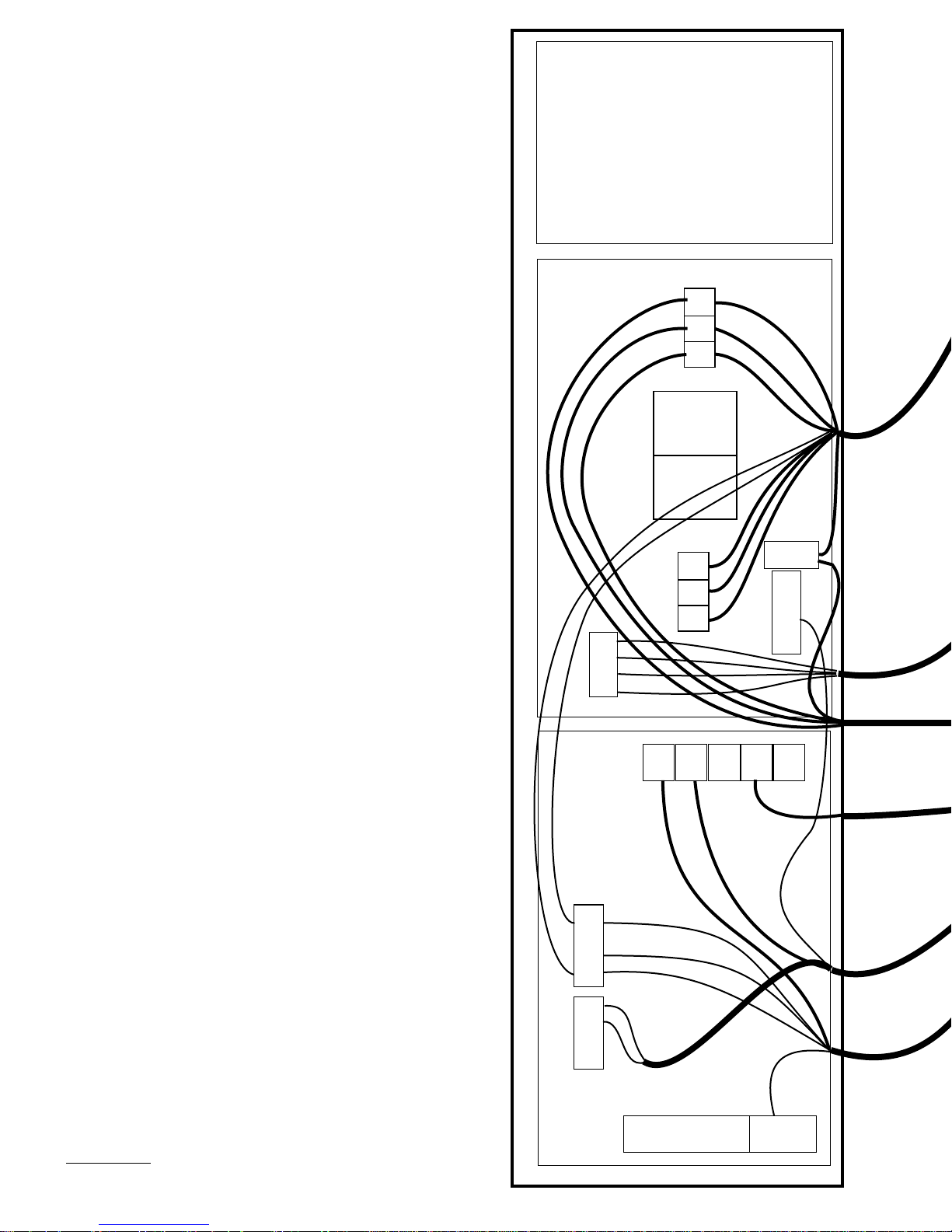
RIGHT (MODULE)SECTION
MIDDLE (DRIVE) SECTION
4
F
2
3
3
2
TBI
2
1
1
TB2
DRIVE MOTORS
T3
T2
T1
L3
L2
L1
TB3
PUMP MOTORS
N
R
G
/
L
Y
GROUND
N
R
G
/
L
Y
GROUND
W9CBW3TG5
2002045B
G3 CBW MAIN CONTROL BOX
LEFT (STANDARD OUTPUT) SECTION
E
T
I
H
W
/
E
U
L
B
K
C
A
L
B
SERIAL LINK
120V POWER
FEED MENTOR
2F
LAB
LAA
L1
SRL
K
SRH
D
E
CONNECTION
WCX
WCM
R
O
T
C
U
D
N
O
H
W
/
L
B
D
E
R
K
C
A
L
B
C
A
L
B
R
L
E
I
H
S
WCH
E
L
B
A
C
D
E
D
L
E
I
C
H
-
I
S
T
L
U
M
E
L
B
A
C
D
E
D
TBC
.
D
N
CUSTOMER CONNECTIONS
WCCW
O
C
-
I
/
W
N
G
/
L
Y
T
E
E
R
G
O
L
L
WCJ
L
U
N
E
Y
GROUND
M
82
Page 89
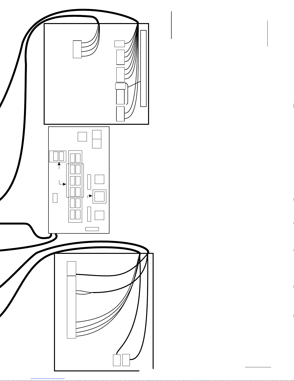
E
L
B
A
C
R
O
T
O
M
/
P
M
U
P
TBJ
F
4
2
3
3
2
2
1
1
TB2
DRIVE
MOTORS
GND
Y
T3
T2
T1
N
R
G
/
L
2002045G
B2T2000005
2002045B
W9CBW3TG5
L3
L2
L1
TB3
PUMP
MOTORS
GND
L3
L2
L1
TB1
H
K
C
INCOMING PWR FROM FUSED DISCONNECT
W
/
L
2F
E
L
B
A
C
C
I
G
O
L
R
E
T
R
E
V
N
I
INVERTER CONTROL BOX
WCL
WCCW
CRUN3CRUN1CRWTCRCWHCR01CD02
CBMC
CSCF CSCR
CRSCCRUN2CRCW0CRCWLCLSCCRSCA
TB4
L1
B
A
L
B
M
ONLY
CONWAY
WCL
V
O
N
C
P
W
N
C
.
V
N
O
C
E
W
O
P
R
O
T
N
E
OPTIONAL LOADING CONV. BOX
R
.
L
L
A
I
R
E
L
R
T
E
L
B
A
C
R
S
TBM
GND
MSL
MSH
DSL
DSH
B
SRL
SRH
TSL
TSH
V3
V2
V1
2G
2F
GND
FAC
LAA
2F
L1
L
A
C
D
E
L
L
E
Y
D
E
R
U
L
B
C
A
L
B
TBP
ONLY
CONWAY
TBC
C
N
I
K
R
W
O
/W
E
K
GND
EXCL
CRCBL
B
L
C
A
B
L
C
K
E
W9CBW3TG5
WIRING HOOKUPS
CONTROL BOX FIELD
PELLERIN MILNOR CORPORATION
G3 CBW SYSTEM MARK 9
MARK 9 SYSTEM, G3 CBW
PELLERIN MILNOR CORPORATION
N
E
E
Y
E
E
I
H
S
N
E
E
R
G
/
E
T
I
H
R
G
/
L
L
W
O
E
L
B
A
C
D
E
D
L
R
O
T
C
U
D
N
O
C
-
I
E
T
L
L
B
U
A
M
C
D
E
D
L
E
I
H
S
FIELD CONNECTIONS OF CABLES BETWEEN CBW AND REMOTE BOXES
MENTOR’S LOWER FRONT CABINET
WCM
WCX
83
W9CBW3TG5
2002045B
Page 90
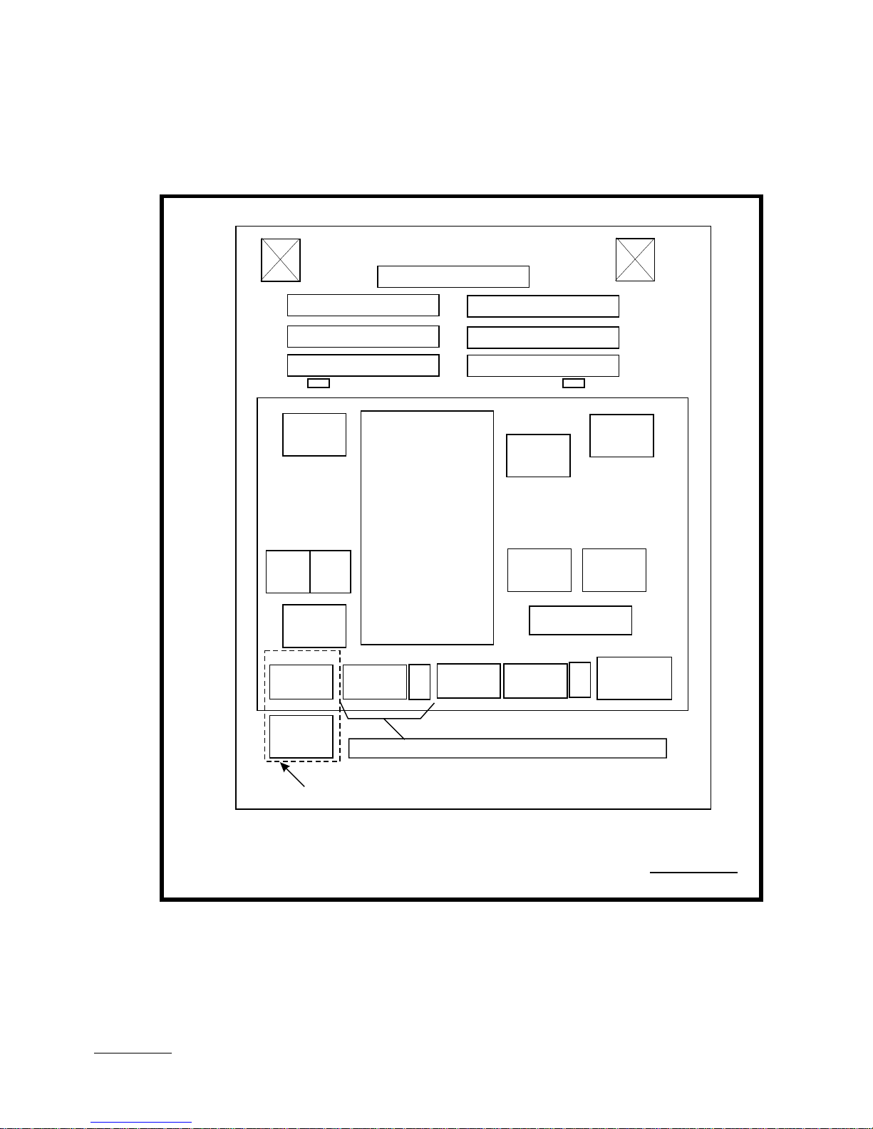
EFM1
RESISTOR
RESISTOR
EFM2
RESISTOR
RESISTOR
RESISTOR
STDB1
INVD1
RESISTOR
RESISTOR
STDB2
INVERTER
CBI CBC
CSI
L1 2F
TB4
SKVA
G3 CBW ONLY
FOR MENTOR’S
POWER
L1 L2 L3 GND
TB1
INCOMING PWR FROM FUSED DISCONNECT
L1 L2 L3
TB3
PUMP
MOTORS
T1 T2 T3 GND
DRIVE
MOTORS
MARK 8/9 CBW SYSTEMS
TBJ
TB2
INVD2
CRBECRAE
GND
REACTOR
W9CBW3TG6
2009233B
INVERTER CONTROL BOX
PELLERIN MILNOR CORPORATION
84
B2TAG94042
2009153A
Page 91

2009233B
W9CBW3TG6
85
W9CBW3TG6
INVERTER CONTROLS
CONTROL BOX LAYOUTS
G3 CBW SYSTEM MARK 9
W9CBW3TG6
2009233B
PELLERIN MILNOR CORPORATION
Page 92
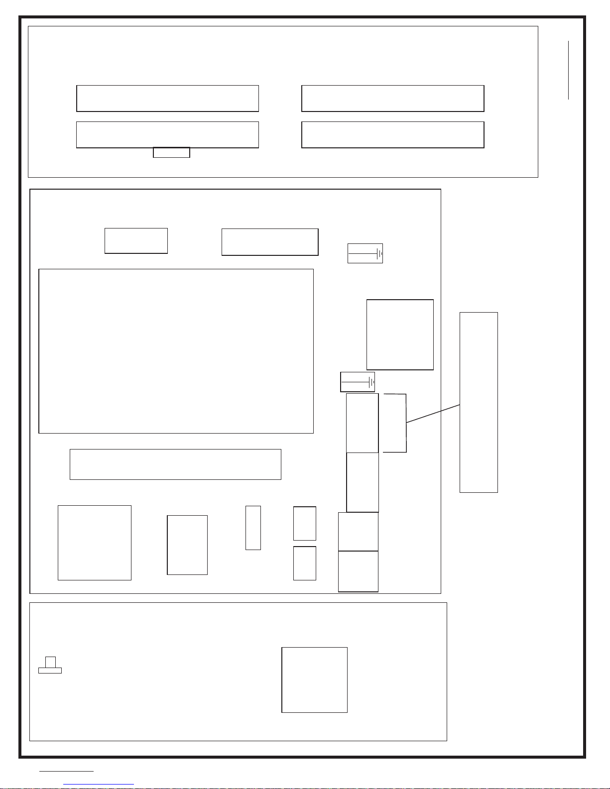
W9CBW3TG7
2015253B
E-STOP
SHED3
SKVA
PS24
CBI CBC
CSI
INVD1
INVFLT
CRBE
CRAE
GND
TB1
TB4
REACTOR
L1 L2 L3
INVERTER
L1 2F
TB
STDB1
RESISTORRESISTOR
RESISTORRESISTOR
RIGHT SIDE
SUBPANEL
MARK 9 CBW SYSTEMS
MAIN CONTROL BOX
INVERTER CONTROLS (LEFT)
PELLERIN MILNOR CORPORATION
B2T2010013
2013346A
LEFT WALL
OF ENCLOSURE
INCOMING POWER
SEPERATE BRANCH CIRCUIT PROTECTION
COPPER CONDUCTUCTORS ONLY
86
Page 93

W9CBW3TG7
G3 CBW SYSTEM MARK 9
CONTROL BOX LAYOUT
LEFT SIDE
PELLERIN MILNOR CORPORATION
W9CBW3TG7
2015253B
W9CBW3TG7
2015253B
87
Page 94
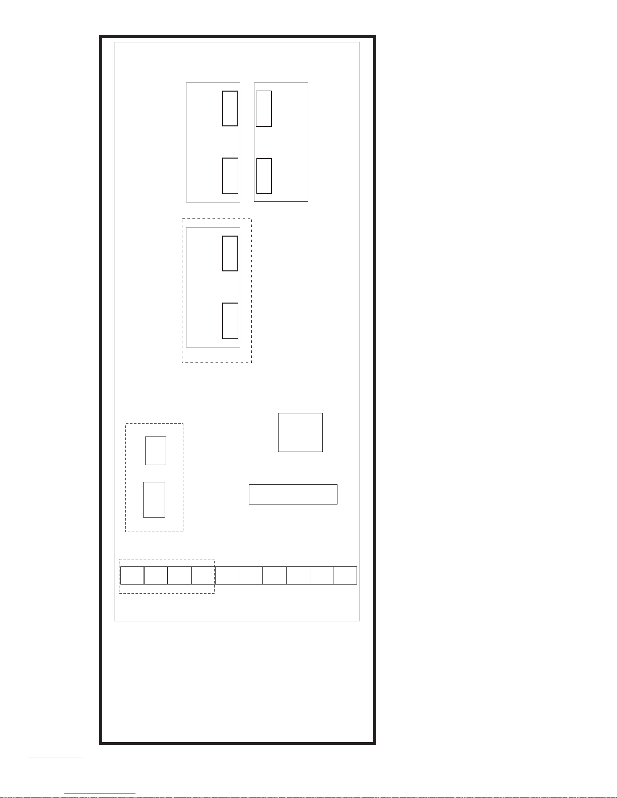
W9CBW3TG8
2015253B
CDWDT
1MTA32
3MTA32
1MTA31
3MTA31
SNUBBER
SNUBBER
TBI
2MTA32
2MTA31
SNUBBER
G3/G4 CBW SYSTEM MARK 9
MAIN CONTROL BOX
LEFT PANEL
PELLERIN MILNOR CORPORATION
B2T2010016
2015253A
___________
CRSBF
CRLD4
CRCBF
CRLD3
CRFI
CRFLLCRFLK CRFE
OPTIONAL
OPTIONAL
OPTIONAL
WCIR
WCIS
88
Page 95
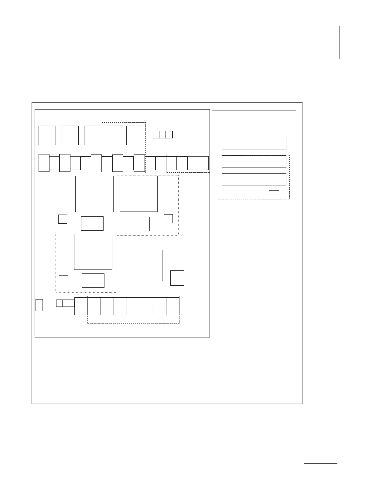
W9CBW3TG8
G3 CBW SYSTEM MARK 9
CONTROL BOX LAYOUTS (CENTER)
FOR MAIN CONTROLAND INTERPRET RELAY BOX
PELLERIN MILNOR CORPORATION
W9CBW3TG8
2015253B
W9CBW3TG8
2015253B
DYNAMIC BRAKE RESISTOR
DYNAMIC BRAKE RESISTOR
DYNAMIC BRAKE RESISTOR
ETDB
ETDB
ETDB
CRPFE
CRSLA CRFFX
CRFFZ
CRSL CRFFY
CRFF1
TBD
CSMPFCSFPM1
CSIP1
CSMPFE
MVPFE
MVPFG
REACTOR
INVERTER
CBMPFCBFPM1
CBIP1
CBMPFG
L1 L2
L3
T1 T2
T3
LINE
FILTER
DRIVE MOTOR
POWER FROM
INVERTER
PUMP MOTOR
POWER FROM
INVERTER
ETBM7ETBM
8
CRPFG
REACTOR
INVERTER
LINE
FILTER
G3-G4 CBW SYSTEM MARK 9
MAIN CONTROL BOX
PULSE FLOW CONTROLS
RIGHT SIDE
SUBPANEL
B2T2011010
2013423A
___________
CRFG
WPPF
CSMPFG
CBMPFE
OPTIONAL
OPTIONAL 1RELAYFOR EACH FAST FILL MODULE
CREPCRPF
OPTIONAL
OPTIONAL
OPTIONAL
ETBM5ETBM
6
MVIP1
REACTOR
LINE
FILTER
INVERTER
ETBM3ETBM
4
ETBM1ETBM
2
OPTIONAL
FLUSH
PUMP
RECIRC.
PUMP
PULSE
FLOW
MAIN
PULSE FLOW
MAIN
PULSE
FLOW
1ST MID
MODULE
PULSE
FLOW
2ND MID
MODULE
PULSE FLOW
2ND MID MODULE
PULSE FLOW
1ST MID MODULE
WCDS
89
Page 96
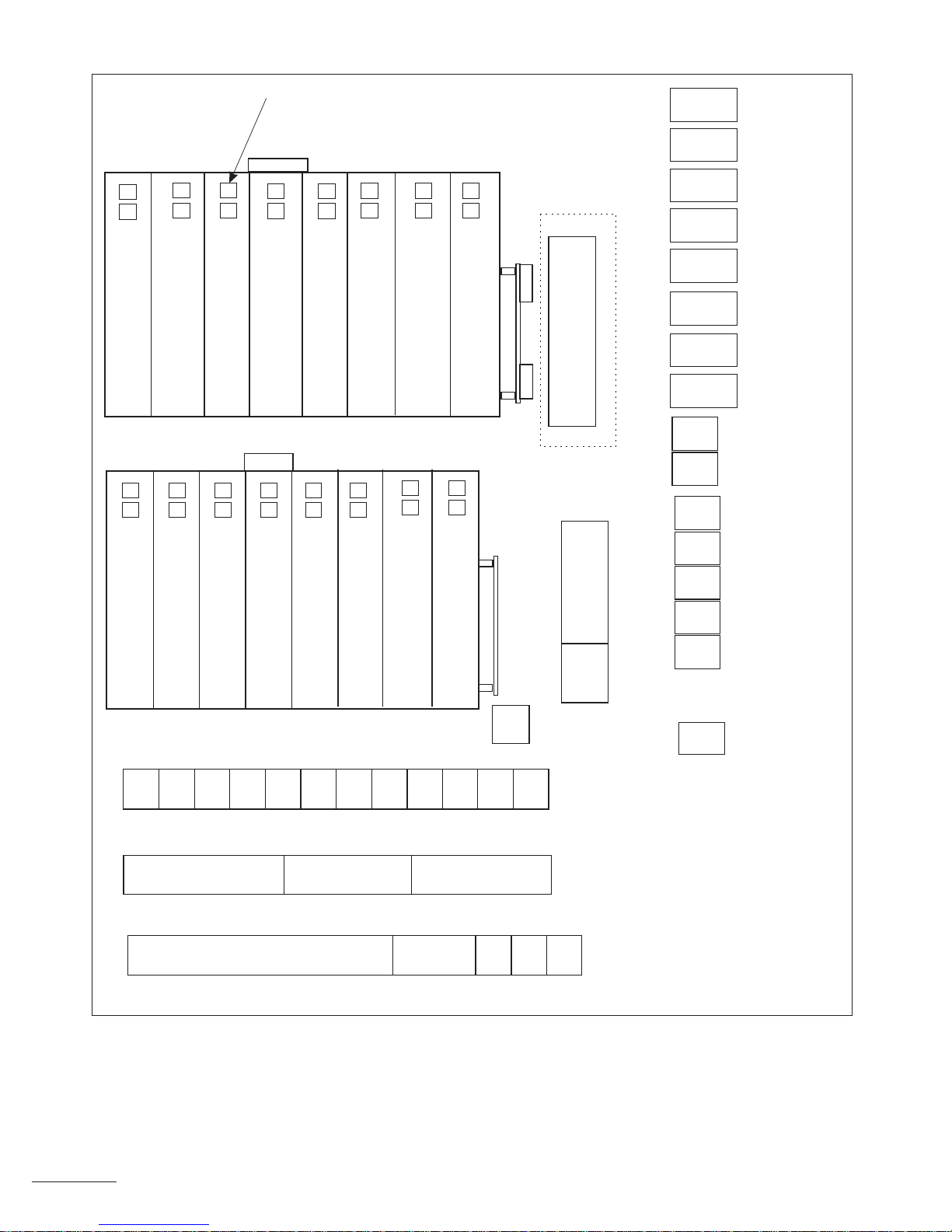
W9CBW3TG9
2015253B
AMTA
BO24-0 ( 24 OUTPUT BOARD #0)
BO24-1 ( 24 OUTPUT BOARD #X)
ATO D CONVERTOR
ATO D CONVERTOR
ATO D CONVERTOR
BIO-2 (8OUTPUT/16INPUT BOARD #2)
BIO-3 (8OUTPUT/16INPUT BOARD #3)
FOR FOR ALLIED INTERFACE
FOR TEMPERATURE MODULES 1 THRU 8
FOR TEMPERATURE MODULES 8 THRU 16
FOR OVERHEAD FILL TANKS
BIO1 (8 OUTPUT/16INPUT BOARD #1)
SW1 SW2
SW1 SW2
SW1 SW2
SW1 SW2
SW1 SW2
SW1 SW2
SW1 SW2
SW1 SW2
ADDRESS
ADDRESS
ADDRESS
ADDRESS
ADDRESS
ADDRESS
ADDRESS
ADDRESS
0
0
0
A
1
1
2
2
2
3
1
0
X
0
1
2
X REPRESENTS
NEXTAVAILABLE
ADDRESS FOR A
24 OUTPUT BOARD
BAS-A
SNUBBER BOARD
WCM
WCU
WCH
WCX
WCCW
CRAB
CRNS8
CRST2
CRST1
CRLCB
CRHN
CRUN8
CRCBS
WCAB
WCIR
BIO-B (8 OUTPUT-16 INPUTBOARD)
(OPTIONAL FOR INTERPRET RELAYS)
BIO-A (8 OUTPUT-16 INPUT BOARD)
BO24-1 (24OUTPUT BOARD 1)
SW1 SW2
SW1 SW2
SW1 SW2
ADDRESS
ADDRESS
ADDRESS
8
0
1
0
0
1
(OPTIONAL FOR 32 INTERPRET RELAYS)
BO24-2 (24OUTPUT BOARD 2)
SW1 SW2
ADDRESS
1
2
MAGNETIC FLOW METERS
ALLIED WEIGHT
MAGNETIC FLOW METERS
MAGNETIC FLOW METERS
BI0-8 (8/16 HIGH SPEED)
BI0-4 (8 OUTPUT-16 INPUTBOARD)
SW1 SW2
SW1 SW2
ADDRESS
ADDRESS
8
4
1
F
D/A HIGH RESOLUTION (BOARD #1)
D/A HIGH RESOLUTION (BOARD #2)
SW1 SW2
ADDRESS
3
1
SW1 SW2
ADDRESS
3
2
1MTP
MODULE BOARDS
1MTD
ESPS2
OPTIONAL
TBE
INPUTS FOR
1ST 8/16 BOARD
INPUTS FOR
2ND 8/16 BOARD
ANALOG INPUTS FOR
TEMP. MOD 1 THRU 8
OUTPUTS FOR
2ND 8/18 BOARD/
24 OUTPUT
INPUTS FOR
3RD 8/16 BOARD
OUTPUTS FOR
1ST 8/16 BOARD/
24 OUTPUT
ANALOG INPUTS FOR
TEMP MOD 9 THRU 16
OUTPUTS FOR
3RD 8/16 BOARD/
24 OUTPUT
WCB-1
WCB-2
WCB-3
WCT-1
WCT-2
WCA-1
WCA-2
WCA-3
CRWDT
CREST
CRCB
CRMF
CRXM1
CRCN1H
CRFLI
WCU
SERIAL LINK CONNECTION
TBC
GROUND
TBD
G3-G4 CBW SYSTEM MARK 9
MAIN CONTROL BOX
RIGHT SECTION
PELLERIN MILNOR CORPORATION
B2T2010014
2015253A
___________
CUSTOMER CONNECTION
POWER SUPPLY
120V POWER FEED
TO MENTOR
STANDARD OUTPUTS
GROUND
TBP
STANDARD OUTPUTBOARDS
AMTA1
TBB
WCU
WCIS
DATAPASS
DATAPASS
90
Page 97
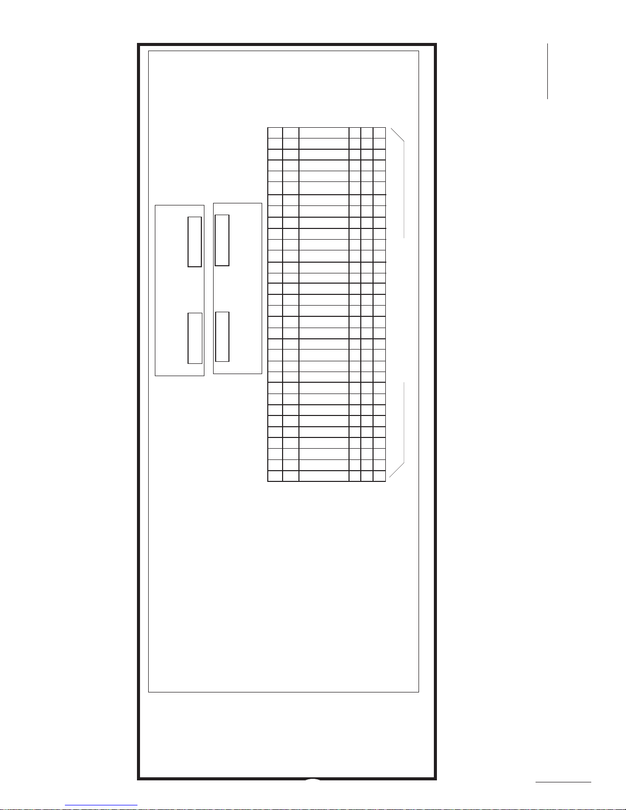
W9CBW3TG9
G3 CBW SYSTEM MARK 9
CONTROL BOX LAYOUTS (RIGHT)
FOR MAIN CONTROL BOX
PELLERIN MILNOR CORPORATION
W9CBW3TG9
2015253B
W9CBW3TG9
2015253B
32 INTERPRET RELAYS
INTERPRET RELAY PANEL
PELLERIN MILNOR CORPORATION
G3/G4 CBW SYSTEM MARK 9
B2T2010015
2015124A
___________
1MTA32
SNUBBER
1MTA31
2MTA32
2MTA31
SNUBBER
CRI 7
CRI 9
CRI12
CRI10
CRI 2
CRI13
CRI15
CRI 3
CRI 1
CRJ18
CRI16
CRJ21
CRJ19
CRI 4
CRI 6
CRI 5
CRI 8
CRI11
CRI14
CRJ17
CRJ20
CRJ23
CRJ26
CRJ28
CRJ30
CRJ32
CRJ22
CRJ24
CRJ25
CRJ27
CRJ31
CRJ29
1411A212A1
INTERPRET RELAYS
11= COMMON
14 = NORMALLY
OPEN
91
Page 98
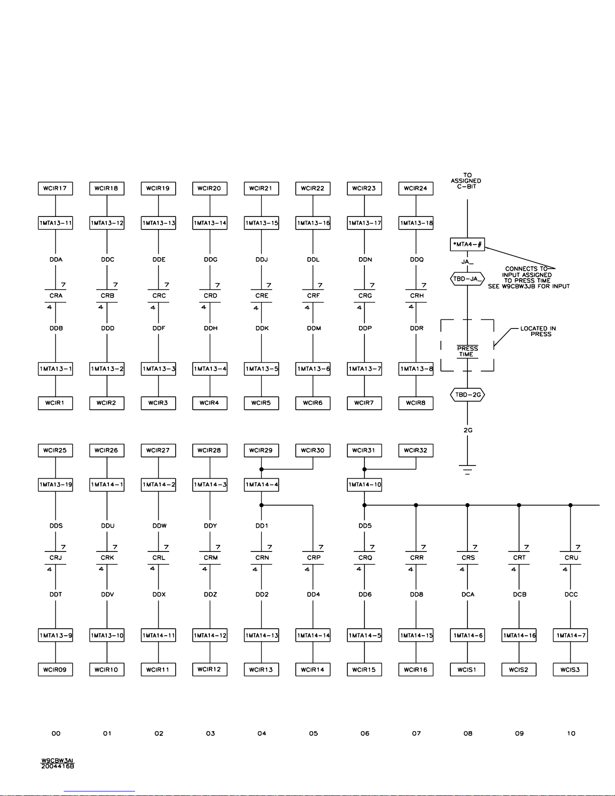
92
Page 99
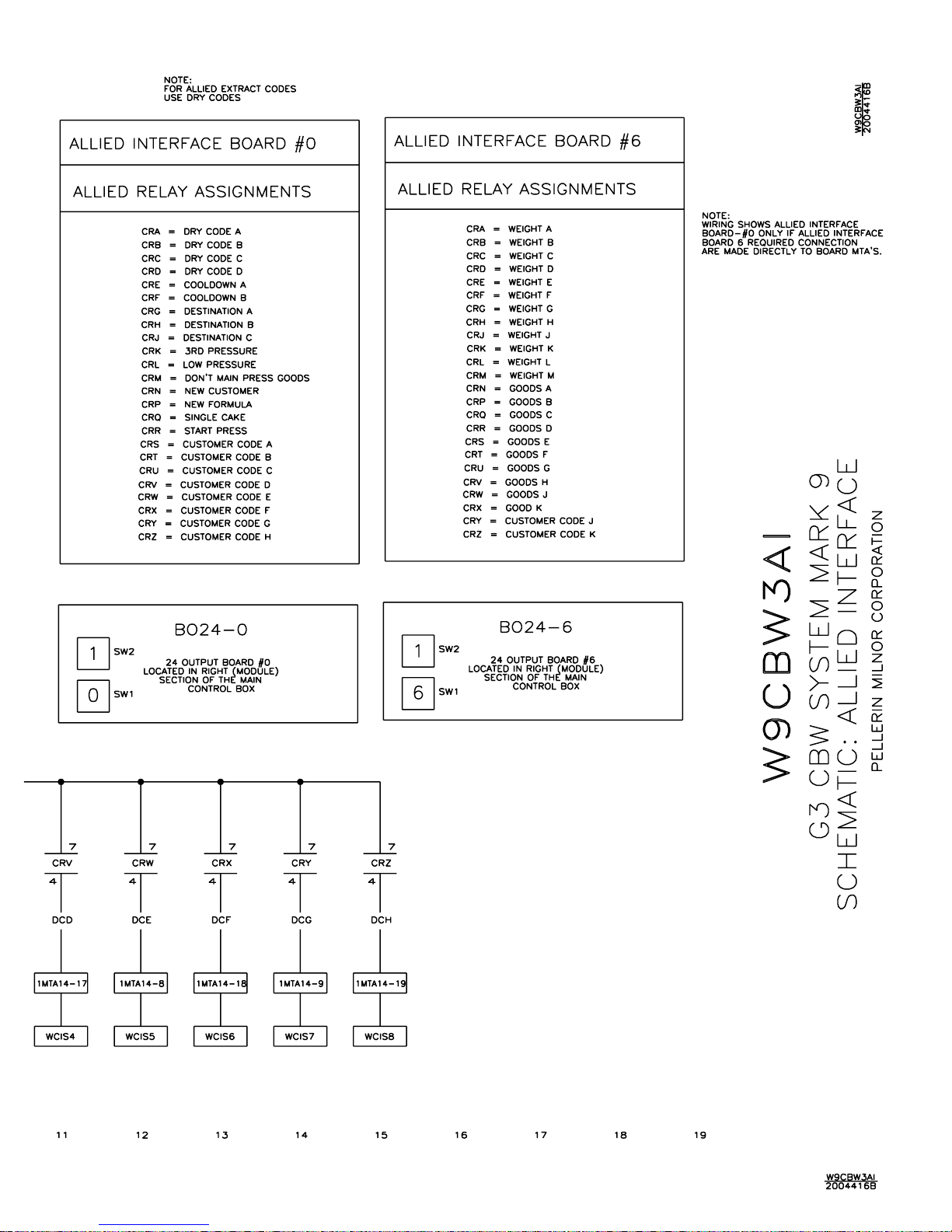
93
Page 100
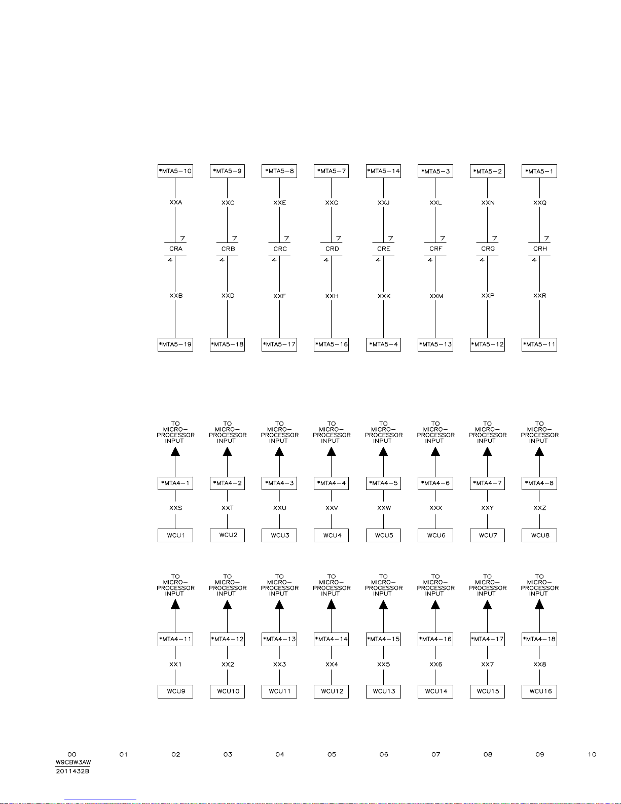
94
 Loading...