

Milnor 72044 WP3, 72044 WP2 Service Manual

Published Manual Number/ECN: MPP72WE2AE/2006153A
• Publishing System: TPAS
• Access date: 4/11/2006
• Document ECN's: Latest Available
Service—
72044 WP2/WP3 Washer-
Extractors
PELLERIN MILNOR CORPORATION POST OFFICE BOX 400, KENNER, LOUISIANA 70063-0400, U.S.A.

Please Read
About the Manual Identifying Information on the Cover
The front cover displays pertinent identifying information for this manual. Most important, are
the published manual number (part number) /ECN (date code). Generally, when a replacement
manual is furnished, it will have the same published manual number, but the latest available ECN.
This provides the user with the latest information applicable to his machine. Similarly all
documents comprising the manual will be the latest available as of the date the manual was
printed, even though older ECN dates for those documents may be listed in the table of
contents.
When communicating with the Milnor factory regarding this manual, please also provide the
other identifying information shown on the cover, including the publishing system, access date,
and whether the document ECN’s are the latest available or exact.
References to Yellow Troubleshooting Pages
This manual may contain references to “yellow pages.” Although the pages containing
troubleshooting procedures are no longer printed on yellow paper, troubleshooting instructions, if
any, will be contained in the easily located “Troubleshooting” chapter or section. See the table of
contents.
Trademarks of Pellerin Milnor Corporation
The following, some of which may be used in this manual, are trademarks of Pellerin Milnor
Corporation:
®
Ampsaver
Autolint
®
Auto-Purge
Autovac E-P OneTouch® Mildata
®
CBW
Dye-Extractor® Gear Guardian
Dyextractor® Hands-Off
®
E-P Express® Hydro-Cushion
E-P Plus
®
®
®
®
®
®
Milnet
Milnor
®
Staph-Guard
System 4
Miltrac System 7
Miltron Totaltrol
®
®
®
®
Comments and Suggestions
Help us to improve this manual by sending your comments to:
Pellerin Milnor Corporation
Attn: Technical Publications
P. O. Box 400
Kenner, LA 70063-0400
Fax: (504) 469-1849

Table of Contents
for MPP72WE2AE/2006153A
72044 WP2/WP3 Washer-Extractors
Page Description Document/ECN
1 About This Manual MHPHYDROAE/9541AV
3 Warranty BMP720097/92732A
4 How to Order Parts BMP720097R/72332A
5 Safety—Divided Cylinder and Staph-Guard™
Washer-Extractors BIUUUS27/20051111
10 About the Forces Transmitted by Milnor Washer-Extractors BIWUUI02/20001108
12 Glossary of Tag Illustrations - Suspended Washer-
Extractors MSIUPUTGAE/2003026V
18 Avoiding Damage from Allied Remote Chemical
Delivery Systems BIWUUI03/20030306
23 Section 1: Service and Maintenance
24 Lubrication and Preventive Maintenance for Hydrocushion
Machines MSSM0201CE/2004046V
34 Lubricants for Milnor Machines MSSM0132AE/9903AV
35 Baldor Motor Maintenance MSSM0274AE/9731AV
39 General Assembly - Rapid Load 2-Pocket Washer-
Extractor BMP701387/70473
40 General Assembly - WED BMP701387R/71152A
41 Lubrication Chart BMP701226/74113A
42 Lubrication Chart BMP701226R/74113A
43 Location - Lube Points = WED BMP701313/71143A
44 Fastener Torque Requirements MSSM0101CE/9906AV
63 Section 2: Shell and Door Assemblies
64 Door Seal Replacement on Rapid Load Models MSSMA413AE/8530BV
68 7244 WE3 Staph-Guard Door Assembly BMP790020/79492A
69 Parts List - Door Assembly, 7244WE3, SG BMP790020R/98301V
70 60" & 72" WEH - Shell Door Assembly BMP780109/81433B
71 Parts List - Shell Door Assembly, 60 & 72 WEH BMP780109R/81433A
73 Air Operated Vacuum Pump for Door Seals BMP810002/81073A
74 Door Interlock Switch Assembly - 6036, 6044
& 7244 Rapid Load Washer-Extractors BMP701654/70481
75 Parts List - Door Interlock , WED BMP701654R/70481
76 Door Latch Assembly BMP701316/98183V
77 Section 3: Drive Assemblies
78 Drive Base Components on Hydro-Cushion Machines MSSMA407BE/85047V
88 Jackshaft Bearing Assembly - 5238, 6036, 6044,
6442 & 7244 BMP820109/89253C
89 Parts List - Jackshaft Bearing Assembly (52, 60, 64, 72) BMP820109R/89253A
91 Drive Assembly - 7244 WE1/WE2/WE3 (50 +
60 Cycle Machines) BMP840022/86016D

Table of Contents, cont.
Page Description Document/ECN
92 Parts List - Drive Assembly, 7244 WE1/WE2/WE3 BMP840022R/97107V
93 Brake Assembly - 60044 & 72044 WP2/WP3 BMP710022/99512V
94 Reducer Air Seal BMP700392/2002496V
95 Autospot Drive Assembly BMP701411/2000133V
97 Air Operated Autospot Assembly - 60044WP2/WP3
and 72044WP2/WP3 BMP710043/96216V
98 Sensing Unit = Airop Autospot BMP710042/76143D
99 Parts List - Sensing Unit, Airop Autospot BMP710042R/85353A
100 Centrifugal Switch Assembly BMP701195/2000242V
102 Centrifugal Switch Operation BMP701196/81271A
103 V-Belt Tension Adjustments MSSM0301AE/9126BV
105 V-Belt Tension Adjustments for 48", 52", 60"
and 72" Washer-Extractors MSSMA405AE/8737BV
109 Section 4: Bearing Assemblies
110 Main Bearing and Seal Replacement for Divided
Cylinder Machines MSSM0303AE/8451BV
120 Main Bearing Assembly - 60036, 60044 & 72044
WE2, WE3, SG2, SG3 & DA3 BMP840039/84336D
121 Parts List - Main Bearing Assembly BMP840039R/96142V
123 Section 5: Frame, Pivots, and Suspension
124 Hold Down Adjustments 60" & 72" Rapid Load
& Staph-Guard Washer-Extractors BMP701672/71051
125 Hold Down Adjustments - 60" & 72" Rapid Load
and Staph-Guard BMP701672R/71051
126 Suspension Adjustments for Divided Cylinder Machines MSSM0302AE/8414BV
132 Hydro-Cushion Suspension Cylinder - 7244 Rapid
Load & Staph-Guard BMP701629/71047
133 Parts List - Suspension Cylinder Assembly BMP701629R/73261A
135 Suspension Cylinder Locations BMP701235/2000133V
136 Push Down Assembly BMP701671/70526
137 Parts List - Push Down Assembly BMP701671R/70526
138 7244WE3 Cylinder Assembly BMP790019/79477B
139 Parts List - Cylinder Assembly, 7244WE3 BMP790019R/86387A
141 Cylinder Assembly - 6036, 6044, & 7244 WE2 BMP780043/79221B
142 Parts List - Cylinder Assembly, 60 & 70 WE2 BMP780043R/86387A
145 Section 6: Control and Sensing Devices
146 Vibration Safety Switch Adjustments MSSMA408BE/9273BV
148 Vibration Switch Assembly BMP700613/83211A
149 Parts List - Vibration Switch Assembly BMP700613R/83211A
150 Maintenance - Vib Safety Switch BMP750047/81307A
151 Section 7: Chemical Supply Devices
152 Rules for the Field Installation of Pumped-Type
Liquid Supply Systems MSSM0213AE/89457V

Table of Contents, cont.
Page Description Document/ECN
154 Supply Injector Assembly - 7244 BMP701401/71192D
155 Parts List - 72" Supply Injector Assembly BMP701401R/83173A
157 Section 8: Water and Steam Piping and
Assemblies
158 Water Inlet Assembly - 7244 Rapid Load & Staph-Guard BMP701634/89112E
159 Parts List - Water Inlet Assembly BMP701634R/71521A
160 Universal Actuators & Mounting Hardware for
Watts Ball Valves - New Pivot BMP920005/96067V
163 Watts Ball Valves and Repair Kits BMP920007/96066V
165 Pressure Regulators BMP900031/96081V
167 Water Level Float Chamber BMP810111/2003262V
169 Parts List - Water Level Float Chamber Assembly BMP810111R/89256A
171 Water Level Switch Assembly BMP800186/2002226V
172 Stainless Steel Dump Valve Air or Water Operated BMP701370/70102
173 Parts List - Stainless Steel Dump Valve Assembly BMP701370R/72431A
174 Burket Steam Valve BMP800020/96066V
175 Steam Sparger Assemblies BMP900001/96132V
177 Section 9: Pneumatic Piping and Assemblies
178 3 Way Pilot Valves BMP900032/91182V
179 Asco 3-way Solenoid Valves BMP701359/97086V
181 ½" ASCO N.C. Valve Assembly BMP701394/71463A
182 Parts List - ½" ASCO N.C. Valve BMP701394R/81377A
183 Universal Airvalve Box Assembly BMP780088/83457C
184 Parts List - Universal Airvalve Box BMP780088R/93046N
186 Air Valves & Mounting Hardware BMP780087/83457B
187 Parts List - Air Valves & Mounting Hardware BMP780087R/83457A
189 Servicing Air Cylinders MSSM0130AE/9313AV
191 Air Cylinders for 2"Watts Ball Valves BMP920006/2000133V
193 Air Cylinder Assembly, Long (For Smith's Ballvalves) BMP701660/89111B
194 Parts List - Long Air Cylinder Assembly BMP701660R/89111A
196 Quick Exhaust Valves BMP701406/2002382V
198 Air Cylinder Assemblies BMP830078/2005525B


MHPHYDROAE/9541AV (1 of 1)
ÈABOUT THIS MANUAL
ËScope—This instruction manual is intended to provide preventive maintenance, service procedures, an d
mechanical parts identification for your machine. See the safety manual for safety instructions before installing,
servicing, or operating this machine. See the installation guide for facility requirements, installation instructions,
and assembly instructions. See the operator guide for operator instructions. See the reference manual for programming, operating, and troubleshooting instructions. See the schematic manual for electrical parts identification and
electrical troubleshooting.
ËManual Number/Date Code (When To Discard or Save)—The manual number/date code is lo-
cated on the inside front cover, upper right corner just above the manual name. Whenever the manual is reprinted
with new information, part of this number changes. If the date code after the “/” changes, the new version applies
to all machines covered by the old version, but is improved— thus the old version can be discarded. If the
manual number before the “/” changes, the new manual covers only new machines. Example: Discard MAT-
MODELAE/8739CV when MATMODELAE/8739DV is received (minor improvements). Also, discard MATMODELAE/8739DV when MATMODELAE/8746AV is received (major improvements). But keep
MATMODELAE/8746FV when MATMODELBE/8815AV is received, since the new manual no longer applies to
machines originally shipped with the old manual.
ËDocuments and Change Bars —The individual documents comprising this manual use the same revision
criteria as the manual. Text documents also display change bars. Example: When section MSOP0599AE/9135BV
becomes MSOP0599AE/9135CV, change bars with the letter “C” appear next to all changes for this revision. For
a major rewrite (e.g., MSOP0599AE/9226AV), all change bars are deleted.
ËTrademarks of Pellerin Milnor Corporation—The following, some of which may be used in this pub-
lication, are trademarks of Pellerin Milnor Corporation:
Ampsaver
®
Autolint
®
Auto-Purge
®
Autovac
CBW
®
Dye-Extractor
®
Dyextractor
®
E-P Plus
®
Gear Guardian
®
Hands-Off
®
Hydro-Cushion
®
Mildata
®
Milnet
®
Milnor
®
Miltrac
Miltron
Staph-Guard
®
System 4
®
System 7
®
Totaltrol
®
ËFor Assistance—Please call:
Pellerin Milnor Corporation
Attn: Service Department
P. O. Box 400
Kenner, LA 70063-0400
Phone: (504) 467-9591
Fax: (504) 467-9777


3(//(5,10,/125&25325$7,21
/,0,7('67$1'$5':$55$17<
We warrant to the original purchaser that MILNOR machines including electronic
hardware/software (hereafter referred to as “equipment”), will be free from defects in material
and workmanship for a period of one year from the date of shipment from our factory with no
operating hour limitation. This warranty is contingent upon the equipment being installed,
operated and serviced as specified in the operating manual supplied with the equipment, and
operated under normal conditions by competent operators.
Providing we receive written notification of a warranted defect within 30 days of its discovery,
we will – at our option – repair or replace the defective part or parts, FOB our factory. We
retain the right to require inspection of the parts claimed defective in our factory prior to
repairing or replacing same. We will not be responsible, or in any way liable, for unauthorized
repairs or service to our equipment, and this warranty shall be void if the equipment is repaired
or altered in any way without MILNOR’s written consent.
Parts which require routine replacement due to normal wear – such as gaskets, contact points,
brake and clutch linings and similar parts – are not covered by this warranty, nor are parts
damaged by exposure to weather or to chemicals.
We reserve the right to make changes in the design and/or construction of our equipment
(including purchased components) without obligation to change any equipment previously
supplied.
ANY SALE OR FURNISHING OF ANY EQUIPMENT BY MILNOR IS MADE ONLY UPON
THE EXPRESS UNDERSTANDING THAT MILNOR MAKES NO EXPRESSED OR IMPLIED
WARRANTIES OF MERCHANTABILITY OR FITNESS FOR ANY PARTICULAR USE OR
PURPOSE. MILNOR WILL NOT BE RESPONSIBLE FOR ANY COSTS OR DAMAGES
ACTUALLY INCURRED OR REQUIRED AS A RESULT OF: THE FAILURE OF ANY OTHER
PERSON OR ENTITY TO PERFORM ITS RESPONSIBILITIES, FIRE OR OTHER HAZARD,
ACCIDENT, IMPROPER STORAGE, MISUSE, NEGLECT, POWER OR ENVIRONMENTAL
CONTROL MALFUNCTIONS, DAMAGE FROM LIQUIDS, OR ANY OTHER CAUSE BEYOND
THE NORMAL RANGE OF USE. REGARDLESS OF HOW CAUSED, IN NO EVENT SHALL
MILNOR BE LIABLE FOR SPECIAL, INDIRECT, PUNITIVE, LIQUIDATED, OR
CONSEQUENTIAL COSTS OR DAMAGES, OR ANY COSTS OR DAMAGES WHATSOEVER
WHICH EXCEED THE PRICE PAID TO MILNOR FOR THE EQUIPMENT IT SELLS OR
FURNISHES.
WE NEITHER ASSUME, NOR AUTHORIZE ANY EMPLOYEE OR OTHER PERSON TO
ASSUME FOR US, ANY OTHER RESPONSIBILITY AND/OR LIABILITY IN CONNECTION
WITH THE SALE OR FURNISHING OF OUR EQUIPMENT TO ANY BUYER.
BMP720097
92732A

How to order repair parts
Repair parts may be ordered either from the authorized dealer who sold you this
machine, or directly from the MILNOR factory. In most cases, your dealer will
have these parts in stock.
When ordering parts, please be sure to give us the following in formation:
1. Model and serial number of the machine for which the parts are required
2. Part number
3. Name of the part
4. Quantity needed
5. Method of shipment des ired
6. In correspondence regarding motors or electrical controls, please include all
nameplate data, including wiring diagram number and the make or
manufacturer of the motor or controls.
All parts will be shipped C.O.D. transportation charges collect on ly.
Please read this manual
It is strongly recommended that you read the installation and operating manual
before attempting to install or operate your machine. We suggest that this manual
be kept in your business office so that it will not become lo st.
PELLERIN MILNOR CORPORATION
32%2;.(11(5/$ 86$
FAX: Administration 504/468-9307, Engineering 504/469-1849, Service 504/469-9777
BMP720097R
72332A

BIUUUS27 (Published) Book specs- Dates: 20051111 / 20051111 / 20060323 Lang: ENG01 Applic: HDU
Safety—Divided Cylinder and Staph-Guard™ Washer-Extractors
1. General Safety Requirements—Vital Information for
Management Personnel
Incorrect installation, neglected preventive maintenance, abuse, and/or improper repairs, or
changes to the machine can cause unsafe operation and personal injuries, such as multiple
fractures, amputations, or death. The owner or his selected representative (owner/user) is
responsible for understanding and ensuring the proper operation and maintenance of the machine.
The owner/user must familiarize himself with the contents of all machine instruction manuals.
The owner/user should direct any questions about these instructions to a Milnor® dealer or the
Milnor® Service department.
Most regulatory authorities (including OSHA in the USA and CE in Europe) hold the owner/user
ultimately responsible for maintaining a safe working environment. Therefore, the owner/user
must do or ensure the following:
• recognize all foreseeable safety hazards within his facility and take actions to protect his
personnel, equipment, and facility;
• work equipment is suitable, properly adapted, can be used without risks to health or safety,
and is adequately maintained;
• where specific hazards are likely to be involved, access to the equipment is restricted to those
employees given the task of using it;
• only specifically designated workers carry out repairs, modifications, maintenance, or
servicing;
• information, instruction, and training is provided;
• workers and/or their representatives are consulted.
[Document BIUUUS04]
Work equipment must comply with the requirements listed below. The owner/user must verify
that installation and maintenance of equipment is performed in such a way as to support these
requirements:
• control devices must be visible, identifiable, and marked; be located outside dangerous zones;
and not give rise to a hazard due to unintentional operation;
• control systems must be safe and breakdown/damage must not result in danger;
• work equipment is to be stabilized;
• protection against rupture or disintegration of work equipment;
• guarding, to prevent access to danger zones or to stop movements of dangerous parts before
the danger zones are reached. Guards to be robust; not give rise to any additional hazards; not
be easily removed or rendered inoperative; situated at a sufficient distance from the danger
zone; not restrict view of operating cycle; allow fitting, replacing, or maintenance by
restricting access to relevant area and without removal of guard/protection device;
• suitable lighting for working and maintenance areas;
• maintenance to be possible when work equipment is shut down. If not possible, then
protection measures to be carried out outside danger zones;
• work equipment must be appropriate for preventing the risk of fire or overheating; discharges
of gas, dust, liquid, vapor, other substances; explosion of the equipment or substances in it.
PELLERIN MILNOR CORPORATION

Safety—Divided Cylinder and Staph-Guard™ Washer-Extractors
y
y
r
r
1.1. Laundr
Facilit
—Provide a supporting floor that is strong and rigid enough to support–with
a reasonable safety factor and without undue or objectionable deflection–the weight of the fully
loaded machine and the forces transmitted by it during operation. Provide sufficient clearance fo
machine movement. Provide any safety guards, fences, restraints, devices, and verbal and/or
posted restrictions necessary to prevent personnel, machines, or other moving machinery from
accessing the machine or its path. Provide adequate ventilation to carry away heat and vapors.
Ensure service connections to installed machines meet local and national safety standards,
especially regarding the electrical disconnect (see the National Electric Code). Prominently post
safety information, including signs showing the source of electrical disconnect.
1.2. Personnel—Inform personnel about hazard avoidance and the importance of care and
common sense. Provide personnel with the safety and operating instructions that apply to them.
Verify that personnel use proper safety and operating procedures. Verify that personnel
understand and abide by the warnings on the machine and precautions in the instruction manuals.
1.3. Safety Devices—Ensure that no one eliminates or disables any safety device on the machine
or in the facility. Do not allow machine to be used with any missing guard, cover, panel or door.
Service any failing or malfunctioning device before operating the machine.
1.4. Hazard Information—Important information on hazards is provided on the machine safety
placards, in the Safety Guide, and throughout the other machine manuals. Placards must be kept
clean so that the information is not obscured. They must be replaced immediately if lost or
damaged. The Safety Guide and other machine manuals must be available at all times to
the appropriate personnel. See the machine service manual for safety placard part numbers.
Contact the Milnor Parts department for replacement placards or manuals.
1.5. Maintenance—Ensure the machine is inspected and serviced in accordance with the norms of
good practice and with the preventive maintenance schedule. Replace belts, pulleys, brake
shoes/disks, clutch plates/tires, rollers, seals, alignment guides, etc. before they are severely
worn. Immediately investigate any evidence of impending failure and make needed repairs (e.g.,
cylinder, shell, or frame cracks; drive components such as motors, gear boxes, bearings, etc.,
whining, grinding, smoking, or becoming abnormally hot; bending or cracking of cylinder, shell,
frame, etc.; leaking seals, hoses, valves, etc.) Do not permit service or maintenance by
unqualified personnel.
2. Safety Alert Messages—Internal Electrical and Mechanical
Hazards
[Document BIUUUS11]
The following are instructions about hazards inside the machine and in electrical enclosures.
WARNING 1 : Electrocution and Electrical Burn Hazards—Contact with electric powe
can kill or seriously injure you. Electric power is present inside the cabinetry unless the main
machine power disconnect is off.
• Do not unlock or open electric box doors.
• Do not remove guards, covers, or panels.
• Do not reach into the machine housing or frame.
• Keep yourself and others off of machine.
• Know the location of the main machine disconnect and use it in an emergency to remove
all electric power from the machine.
PELLERIN MILNOR CORPORATION
WARNING 2 : Entangle and Crush Hazards—Contact with moving components normally
isolated by guards, covers, and panels, can entangle and crush your limbs. These components
move automatically.
• Do not remove guards, covers, or panels.
• Do not reach into the machine housing or frame.
• Keep yourself and others off of machine.
• Know the location of all emergency stop switches, pull cords, and/or kick plates and use
them in an emergency to stop machine motion.
3. Safety Alert Messages—External Mechanical Hazards [Document
BIUUUS12]
The following are instructions about hazards around the front, sides, rear or top of the machine.
WARNING 3 : Crush Hazards—Suspended machines only—Spaces between the shell and
housing can close and crush or pinch your limbs. The shell moves within the housing during
operation.
• Do not reach into the machine housing or frame.
• Keep yourself and others clear of movement areas and paths.
4. Safety Alert Messages—Cylinder and Processing Hazards
[Document BIUUUS13]
The following are instructions about hazards related to the cylinder and laundering process.
WARNING 4 : Crush Hazards—Contact with the turning cylinder can crush your limbs. The
cylinder will repel any object you try to stop it with, possibly causing the object to strike or stab
you. The turning cylinder is normally isolated by the locked cylinder door.
• Do not attempt to open the door or reach into the cylinder until the cylinder is stopped.
• Do not place any object in the turning cylinder.
• Do not operate the machine with a malfunctioning door interlock.
• Divided cylinder machines only—Keep yourself and others clear of cylinder and goods
during inching or Autospot operation.
• Do not operate the machine with malfunctioning two-hand manual controls.
WARNING 5 : Confined Space Hazards—Confinement in the cylinder can kill or injure
you. Hazards include but are not limited to panic, burns, poisoning, suffocation, heat prostration,
biological contamination, electrocution, and crushing.
• Do not attempt unauthorized servicing, repairs, or modification.
WARNING 6 : Explosion and Fire Hazards—Flammable substances can explode or ignite
in the cylinder, drain trough, or sewer. The machine is designed for washing with water, not any
other solvent. Processing can cause solvent-containing goods to give off flammable vapors.
• Do not use flammable solvents in processing.
• Do not process goods containing flammable substances. Consult with your local fire
department/public safety office and all insurance providers.
PELLERIN MILNOR CORPORATION
Safety—Divided Cylinder and Staph-Guard™ Washer-Extractors
5. Safety Alert Messages—Unsafe Conditions [Document BIUUUS14]
Damage and Malfunction Hazards
5.1.
5.1.1. Hazards Resulting from Inoperative Safety Devices
DANGER 7 : Entangle and Sever Hazards—Cylinder door interlock—Operating the
machine with a malfunctioning door interlock can permit opening the door when the cylinder is
turning and/or starting the cycle with the door open, exposing the turning cylinder.
• Do not operate the machine with any evidence of damage or malfunction.
WARNING 8 : Multiple Hazards—Operating the machine with an inoperative safety device
can kill or injure personnel, damage or destroy the machine, damage property, and/or void the
warranty.
• Do not tamper with or disable any safety device or operate the machine with a
malfunctioning safety device. Request authorized service.
WARNING 9 : Electrocution and Electrical Burn Hazards—Electric box doors—
Operating the machine with any electric box door unlocked can expose high voltage conductors
inside the box.
• Do not unlock or open electric box doors.
WARNING 10 : Entangle and Crush Hazards—Guards, covers, and panels—Operating
the machine with any guard, cover, or panel removed exposes moving components.
• Do not remove guards, covers, or panels.
5.1.2. Hazards Resulting from Damaged Mechanical Devices
WARNING 11 : Multiple Hazards—Operating a damaged machine can kill or injure
personnel, further damage or destroy the machine, damage property, and/or void the warranty.
• Do not operate a damaged or malfunctioning machine. Request authorized service.
WARNING 12 : Explosion Hazards—Cylinder—A damaged cylinder can rip apart during
extraction, puncturing the shell and discharging metal fragments at high speed.
• Do not operate the machine with any evidence of damage or malfunction.
WARNING 13 : Explosion Hazards—Inner door latches (divided cylinder machines)—A
damaged or improperly seated latch can cause the inner door to open during operation, damaging
the cylinder and shell. A damaged cylinder can rip apart during extraction, puncturing the shell
and discharging metal fragments at high speed.
• Ensure that the inner door is securely latched when loading and unloading.
• Do not operate the machine with any evidence of damage or malfunction.
WARNING 14 : Explosion Hazards—Clutch and speed switch (multiple motor
machines)—A damaged clutch or speed switch can permit the low speed motor to engage during
extract. This will over-speed the motor and pulleys and can cause them to rip apart, discharging
metal fragments at high speed.
• Stop the machine immediately if any of these conditions occur: • abnormal whining sound
during extract • skidding sound as extract ends • clutches remain engaged or re-engage
during extract
PELLERIN MILNOR CORPORATION
5.2. Careless Use Hazards
(
5.2.1. Careless Operation Hazards—Vital Information for Operator Personnel
see also
operator hazards throughout manual)
WARNING 15 : Multiple Hazards—Careless operator actions can kill or injure personnel,
damage or destroy the machine, damage property, and/or void the warranty.
• Do not tamper with or disable any safety device or operate the machine with a
malfunctioning safety device. Request authorized service.
• Do not operate a damaged or malfunctioning machine. Request authorized service.
• Do not attempt unauthorized servicing, repairs, or modification.
• Do not use the machine in any manner contrary to the factory instructions.
• Use the machine only for its customary and intended purpose.
• Understand the consequences of operating manually.
5.2.2. Careless Servicing Hazards—Vital Information for Service Personnel (see also
service hazards throughout manuals)
WARNING 16 : Electrocution and Electrical Burn Hazards—Contact with electric
power can kill or seriously injure you. Electric power is present inside the cabinetry unless the
main machine power disconnect is off.
• Do not service the machine unless qualified and authorized. You must clearly understand
the hazards and how to avoid them.
• Abide by the current OSHA lockout/tagout standard when lockout/tagout is called for in
the service instructions. Outside the USA, abide by the OSHA standard in the absence of
any other overriding standard.
WARNING 17 : Entangle and Crush Hazards—Contact with moving components
normally isolated by guards, covers, and panels, can entangle and crush your limbs. These
components move automatically.
• Do not service the machine unless qualified and authorized. You must clearly understand
the hazards and how to avoid them.
• Abide by the current OSHA lockout/tagout standard when lockout/tagout is called for in
the service instructions. Outside the USA, abide by the OSHA standard in the absence of
any other overriding standard.
WARNING 18 : Confined Space Hazards—Confinement in the cylinder can kill or injure
you. Hazards include but are not limited to panic, burns, poisoning, suffocation, heat prostration,
biological contamination, electrocution, and crushing.
• Do not enter the cylinder until it has been thoroughly purged, flushed, drained, cooled,
and immobilized.
— End of BIUUUS27 —
PELLERIN MILNOR CORPORATION

About the Forces Transmitted by Milnor® Washer-extractors
2
8
8
8
U
About the Forces Transmitted by Milnor
Washer-extractors
During washing and extracting, all washer-extractors transmit both static and dynamic
(cyclic) forces to the floor, foundation, or any other supporting structure. During washing, the
impact of the goods as they drop imparts forces which are quite difficult to quantify. Size for size,
both rigid and flexibly-mounted machines transmit approximately the same forces during
washing. During extracting, rigid machines transmit forces up to 30 times greater than equivalent
flexibly-mounted models. The actual magnitude of these forces vary according to several factors:
• machine size,
• final extraction speed,
• amount, condition, and type of goods being processed,
• the liquor level and chemical conditions in the bath preceding extraction, and
• other miscellaneous factors.
Estimates of the maximum force normally encountered are available for each Milnor
and size upon request. Floor or foundation sizes shown on any Milnor
on-grade situations based only on previous experience without implying any warranty, obligation,
or responsibility on our part.
1.
Rigid Machines
Size for size, rigid washer-extractors naturally require a stronger, more rigid floor,
foundation, or other supporting structure than flexibly-mounted models. If the supporting soil
under the slab is itself strong and rigid enough and has not subsided to leave the floor slab
suspended without support, on grade installations can often be made directly to an existing floor
slab if it has enough strength and rigidity to safely withstand our published forces without
transmitting undue vibration. If the subsoil has subsided, or if the floor slab itself has insufficient
strength and rigidity, a deeper foundation, poured as to become monolithic with the floor slab,
may be required. Support pilings may even be required if the subsoil itself is “springy” (i.e., if its
resonant frequency is near the operating speed of the machine). Above-grade installations of rigid
machines also require a sufficiently strong and rigid floor or other supporting structure as
described below.
®
Document..................... BIWUUI0
Specified Date.................2000110
As-of Date.......................2000110
Access Date..................... 2000110
Applicability...........................WU
®
®
document are only for
model
2.
Flexibly-mounted Machines
Size for size, flexibly-mounted machines generally do not require as strong a floor,
foundation, or other supporting structure as do rigid machines. However, a floor or other
supporting structure having sufficient strength and rigidity, as described in section 3, is
nonetheless vitally important for these models as well.
3.
How Strong and Rigid?
Many building codes in the U.S.A. specify that laundry floors must have a minimum live
load capacity of 150 pounds per square foot (732 kilograms per square meter). However, even
compliance with this or any other standard does not necessarily guarantee sufficient rigidity. In
any event, it is the sole responsibility of the owner/user to assure that the floor and/or any other
supporting structure exceeds not only all applicable building codes, but also that the floor and/or
any other supporting structure for each washer-extractor or group of washer-extractors actually
has sufficient strength and rigidity, plus a reasonable factor of safety for both, to support the
weight of all the fully loaded machine(s) including the weight of the water and goods, and
including the published 360º rotating sinusoidal RMS forces that are transmitted by the
machine(s). Moreover, the floor, foundation, or other supporting structure must have sufficient
rigidity (i.e., a natural or resonant frequency many times greater than the machine speed with a
reasonable factor of safety); oth erwise, the m enti oned 360º ro ta ting sinuso ida l RMS forces can be
multiplied and magnified many times. It is especially important to consider all potential vibration
problems that might occur due to all possible combinations of forcing frequencies (rotating
speeds) of the machine(s) compared to the natural frequencies of the floor and/or any other
supporting structure(s). A qualified soil and/or structural engineer must be engaged for this
purpose.
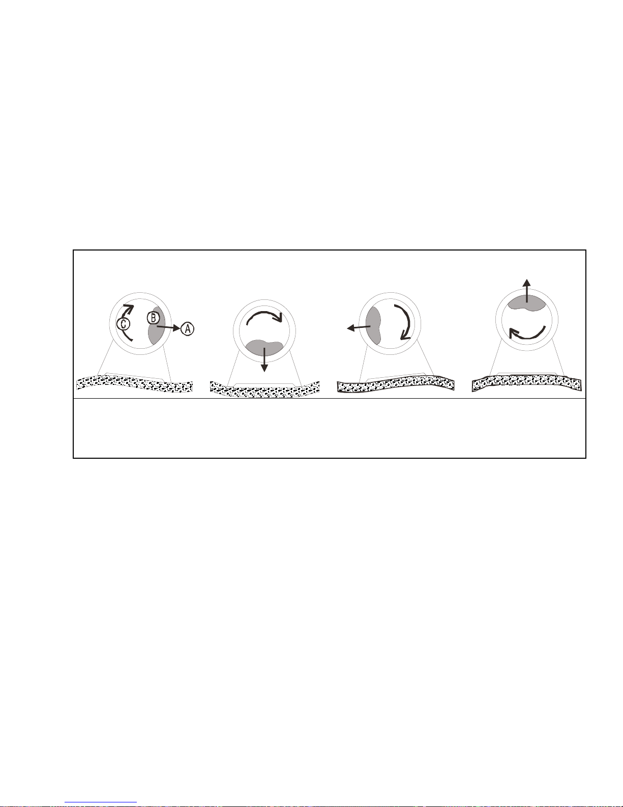
Figure 1: How Rotating Forces Act on the Foundation
Typical Machine
A.
Direction of force
B.
Load
C.
Rotation (Frequency = RPM / 60)
Figure 1 above is intended to depict both on-grade and above-grade installations and is
equally applicable to flexibly-mounted washer-extractors, as well as to rigid models installed
either directly on a floor slab or on a foundation poured integrally with the slab. Current machine
data is available from Milnor
have changed since last printed. It is the sole responsibility of every potential owner to obtain
written confirmation that any data furnished by Milnor
number(s) of the specific machines.
Legend
®
upon request. All data is subject to change without notice and may
®
applies for the model(s) and serial
— End of BIWUUI02 —

7\_ccQbi_VDQW9\\ecdbQdY_^c±
Cec`U^TUTGQcXUb5hdbQSd_bc
Illustration Explanation
Stop! Read the manual first for complete
instructions before continuing.
Do not jack the machine here.
Do not lift the machine here.
<B8D?DC604!"!%E
Use three point or four point lifting as
determined by the lifting eyes furnished. Rig
the load using lifting cables of sufficient size
and length to ensure cables are not
over-stressed.
Do not lift the machine from one corner or one
side edge.
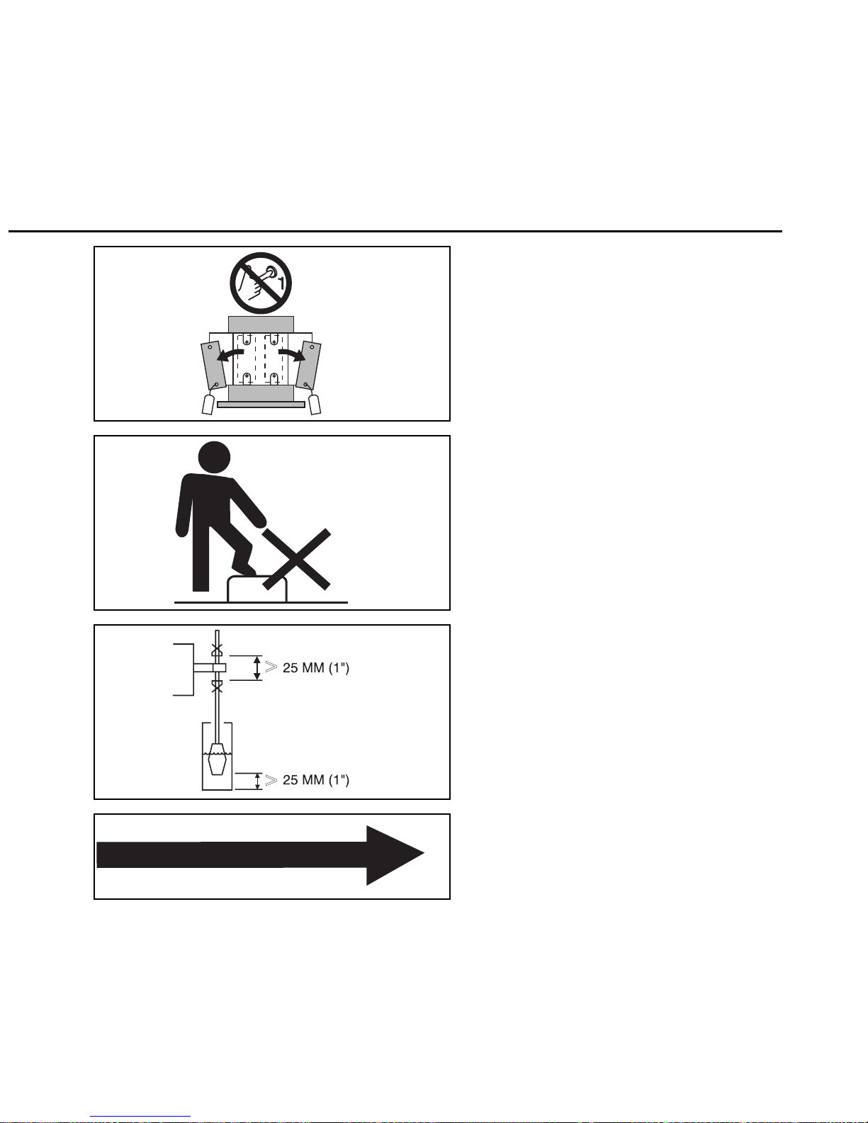
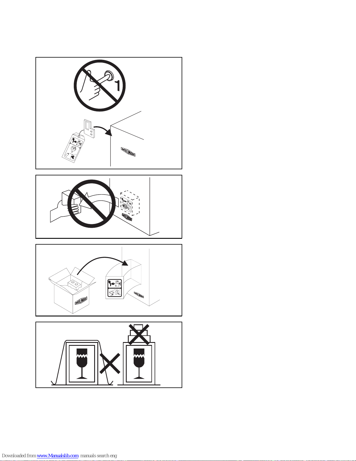
Illustration Explanation
Do not start this machine until the packing
materials, lifting brackets, etc. with this tag
attached or behind this panel are removed.
These materials are painted red. Safety stands
or brackets (also painted red) may be provided
with this machine. Do not discard safety
stands or brackets
Do not step or stand on this machine part.
Maintain a 25 mm. (1") minimum clearance
between float clips. Set "low level" so that the
bottom of the float is always at least 25mm
(1") above the bottom of the float tube.
This motor or pump should rotate in the
direction of the arrow.
7\_ccQbi _V DQW9\\ecdbQdY_^c±
Cec`U^TUT GQcXUb5hdbQSd_bc
Do not start this machine until the part with
this tag is installed on the machine.
Do not remove this component from the
machine.
Install the appropriate part here before
operating the machine.
Do not strap or chain over box
=C9E@ED715" # "&F " #
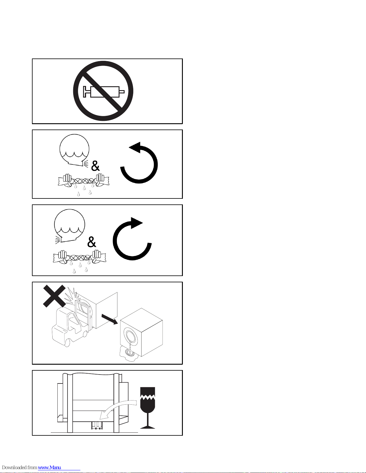
Do not pump grease here.
During drain and extract, the cylinder must
rotate counterclockwise when viewed from
here (rear of machine).
During drain and extract, the cylinder must
rotate clockwise when viewed from here
(front of machine).
Do not strike shell front of washer-extractors
during fork lifting. Striking shell front will
cause door to leak.
Brake assembly under machine is fragile.
Forklift blades should only be placed under
main structural beams
7\_ccQbi _V DQW9\\ecdbQdY_^c±
Cec`U^TUT GQcXUb5hdbQSd_bc
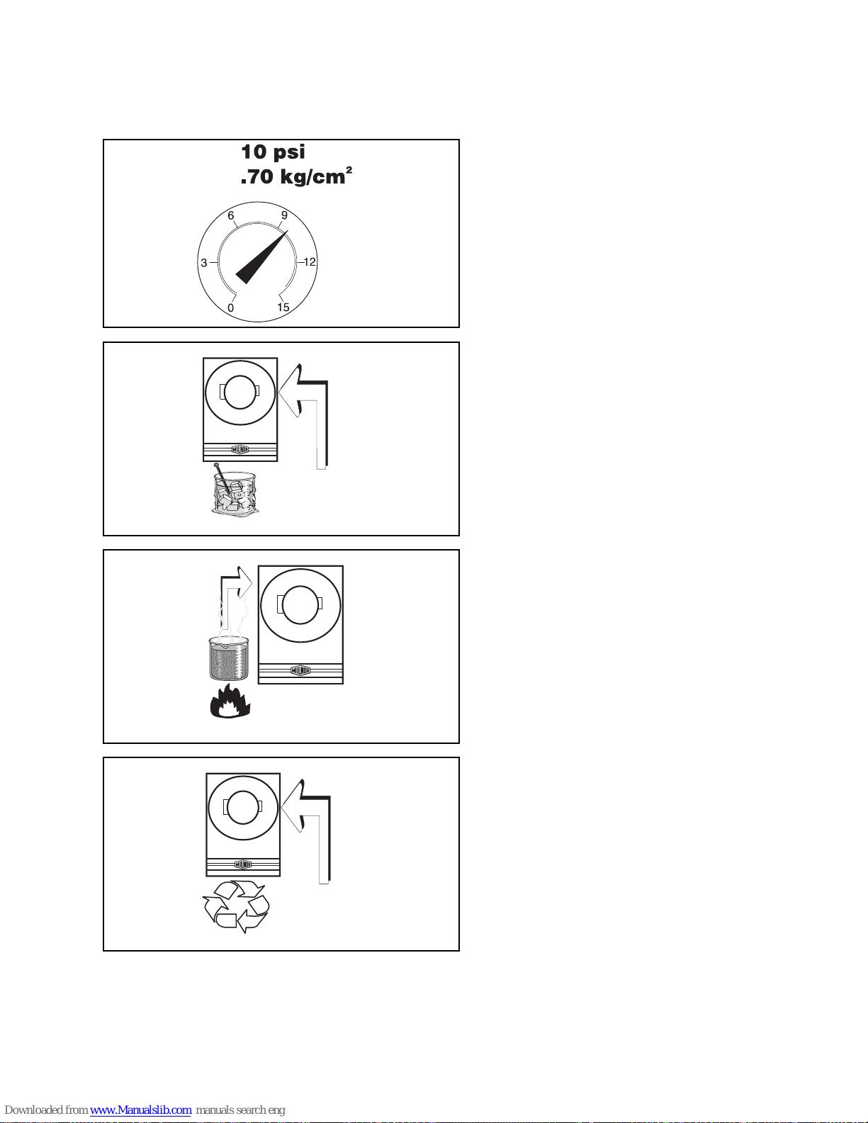
H0
2
Set main bearing air pad gauge at 10 psi
(.70 kg/cm
models only.
Set disc brake air gauge at 10 psi
(.70 kg/cm2), 64" and 72" ExN and JxN
models only.
Make cold water connection here.
Make hot water connection here.
2
), 64" and 72" ExN and JxN
H0
H0
2
Make third (reuse) water connection here.
2
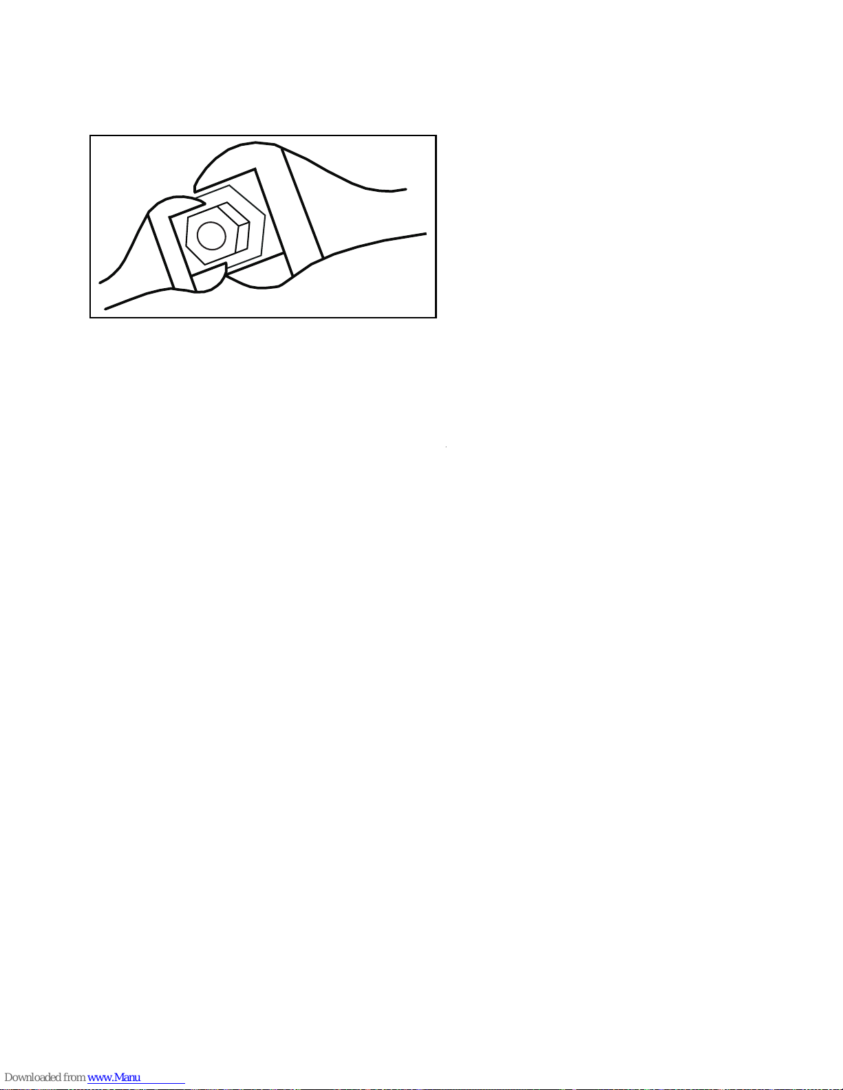
=C9E@ED715" # "&F # #
Hold the connection side of the valve with a
wrench when connecting plumbing.
BIWUUI03 (Published) Book specs- Dates: 20030306 / 20030306 / 20030306 Lang: ENG01 Applic: WUU
Avoiding Damage From Allied Remote Chemical Delivery
Systems
Milnor® does not manufacture or supply remote chemical delivery systems and this document is
meant only to illustrate some of the possible problems that can be minimized during installation
of such systems by the chemical supply company. Milnor washer-extractors and CBW
washers (tunnels) are available with convenient inlets for such systems (see Figure 1). Most
common of the types of systems currently used in commercial laundering operations are pumped
chemical systems. Other types, such as constant pressure, re-circulating ring main systems have
also been, and may continue to be used with Milnor equipment.
This document warns about some of the possible hazards posed by chemical systems and lists
certain requirements needed to minimize those hazards. The procedures for interfacing with allied
chemical systems and information pertinent to chemical use in general are provided elsewhere in
the product manuals (see Note 1).
Figure 1: Pumped Chemical Inlets on CBW Batch Washer
®
batch
Note 1:
permitting acid sours to react with hypo chlorite) due to incorrect formulation can also be hazardous.
Information pertinent to chemical u se is provided elsewhere in th e product manuals.
1.
How a Chemical System Can Damage the Machine It Serves
Misuse of laundering chemicals (such as injecting excessive concentrations of chlorine bl each or
Milnor has manufactured washer-extractors and tunnel washers with the same stainless steel
specification since its founding. Every batch of steel used is certified and documented by the steel
mill. Testing of samples damaged by corrosion have, in every case, proven the steel to be well
within the AISI 304 specification.
PELLERIN MILNOR CORPORATION

Avoiding Damage From Allied Remote Chemical Delivery Systems
Chemical products commonly found in the laundry industry, when used in established dosages
and proper operating parameters, under the auspices of an experienced chemical specialist, should
produce satisfactory results, with no consequential detrimental effects. The industry has published
standards in Riggs and Sherrill, “Textile Laundering Technology”. However, the stainless steel
can be damaged and even destroyed by abnormal contact with chlorine bleach, hydrofluosilicic
acid and other commonly used chemicals, as will occur if chemicals are unintentionally leaked
into the machine, particularly when it is no longer in use and especially when machine surfaces
are dry.
Some chemical systems have been found to permit chemicals to dribble from the supply lines, or
worse, to siphon from the supply tank into the machine, during operation and long after the
system is shut down—as after working hours and during weekends. If this occurs, deterioration
(rusting) of the stainless steel and damage to any textiles therein will inevitably result. If this
condition goes undetected, machine damage is likely to be catastrophic. No machine is
immune to such damage.
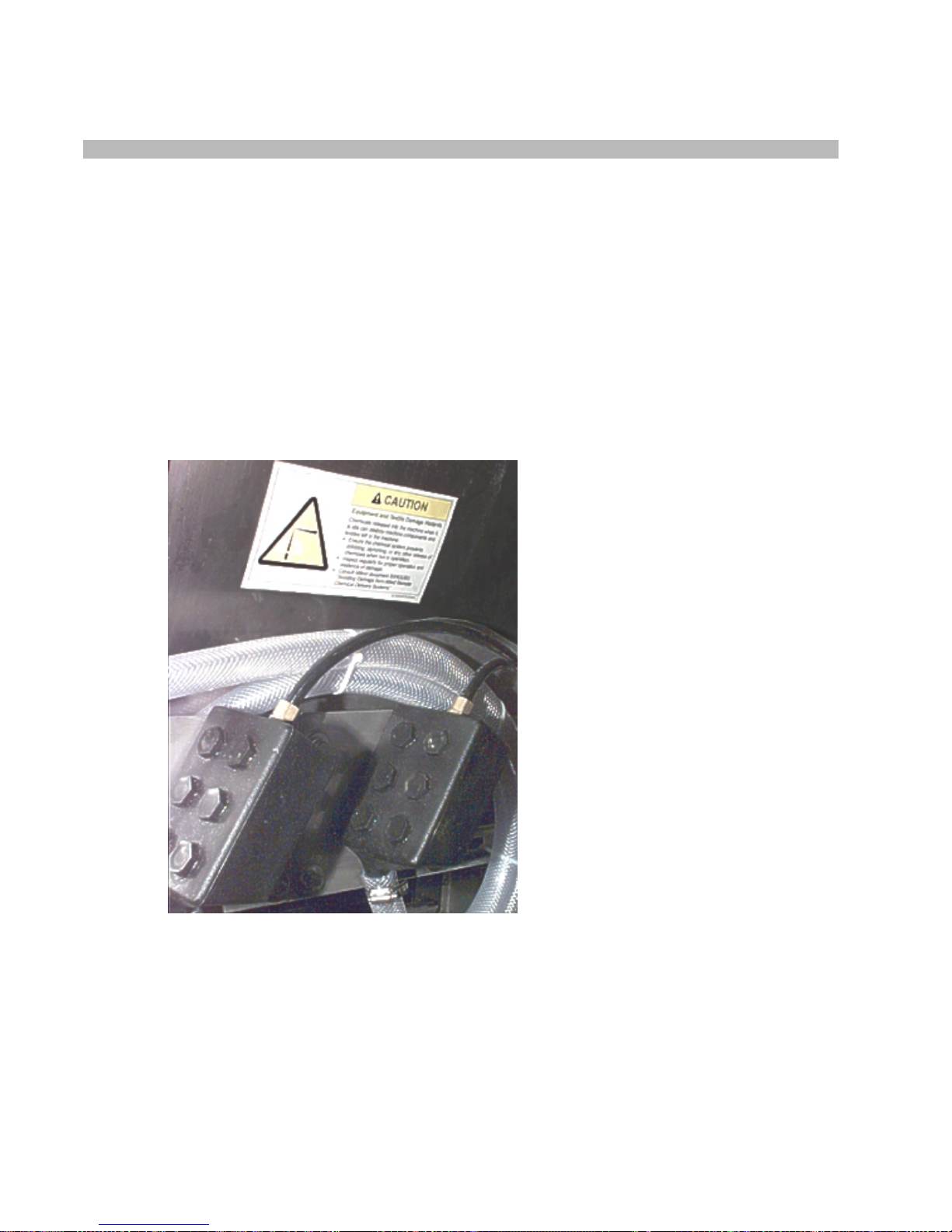
CAUTION 1 : Equipment and Textile Damage Hazards
—Chemicals leaked into the
machine, particularly when it is idle can destroy machine components and textiles left in the
machine. Pellerin Milnor Corporation accepts absolutely no responsibility for damage to its
equipment or to textiles therein from abnormal contact with chemicals.
• Ensure that the chemical system prevents uninten ti ona l rele ase of chemicals.
• Inspect regularly for proper operation and evidence of damage.
2.
Requirements for Chemical Systems Used With Milnor Machines
It is the responsibility of the chemical system manufacturer and supplier to ensure that their
system is safe for personnel and equipment. Some important points are described below.
2.1.
Ensure the System Cannot Siphon.
—The supply system must be designed to
counteract any siphoning that could occur as a result of having a sealed supply line between the
bottom of the chemical tank and the internal machine connection at the drain trough. As shown in
the Figure 2 examples, if the pump (P) and/or the valving does not provide positive closure and
there is no vacuum breaker protection, siphoning is likely to occur. In each of the Figure 2
illustrations, the volume of chem ical in the tank above th e siphon level (S), and indi ca ted by
shading, will flow into the machine.
PELLERIN MILNOR CORPORATION
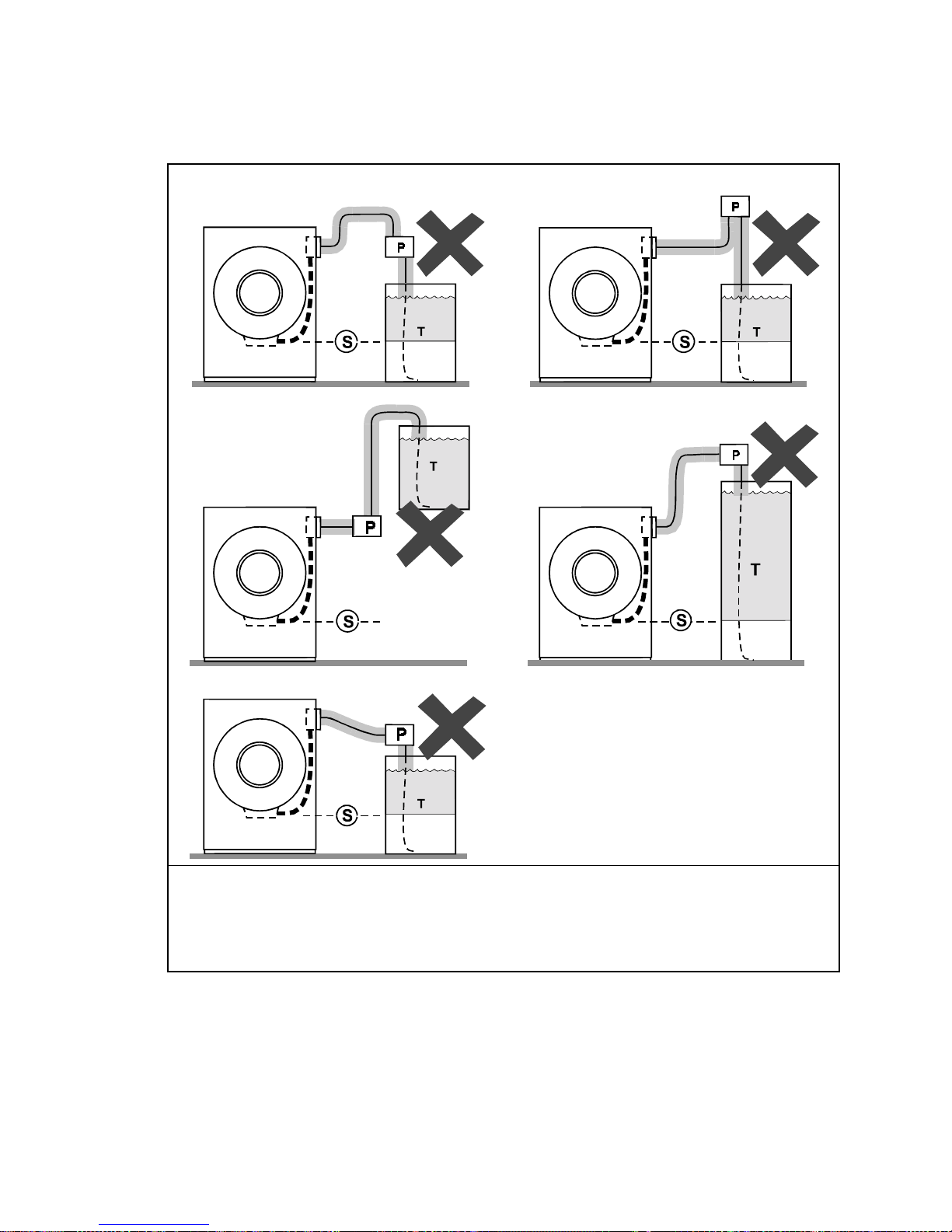
Figure 2:
Siphoning From the Chemical Tank into the Machine
Examples
Pump
P.
Siphon level. Shading indicates the chemical delivery line and tank content that can siphon into
S.
the machine.
Chemical tank
T.
2.2.
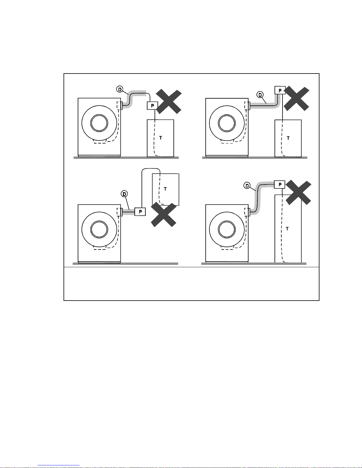
Ensure the Chemical Lines Cannot Dribble
provide a means of positively closing the chemical line at the pump location, but not at the
injection site. Hence, any concentrated chemical that remains in the injection line between the
pump and the machine is free to flow into the machine. Some examples of this are shown in
Figure 3.
Legend
—The pumped chemical system may
PELLERIN MILNOR CORPORATION
Avoiding Damage From Allied Remote Chemical Delivery Systems
Figure 3:
Dribbling From Chemical Supply Line Into Machine
(assumes positive closure at the pump)
Examples
Legend
Portion of supply line, the contents of which can dribble into the machine
D.
Pump
P.
Chemical tank
T.
3.
Design and Installation Recommendations
It is the responsibility of the chemical system manufacturer and supplier to use whatever
measures are necessary to ensure that their system is safe for personnel and equipment. The
following are some of the possible methods the manufacturer or supplier may wish to use, as
appropriate.
3.1.
Siphoning: Positively close the line.
—If the pump does not provide positive closure
when the system is off, employ a shutoff valve in the line to serve this purpose.
3.2.
Siphoning: Break the siphon.
—Provide an air gap or vacuum breaker in the chemical
delivery line. This must be located above the “full” line of the tank.
3.3.
Dribbling: Flush the entire chemical delivery line.
—If any concentrated chemical
that remains in the injection line between the pump and the machine is free to flow into the
machine, employ a system that flushes the entire line between the pump and the injection point
with fresh water after each injection.
PELLERIN MILNOR CORPORATION
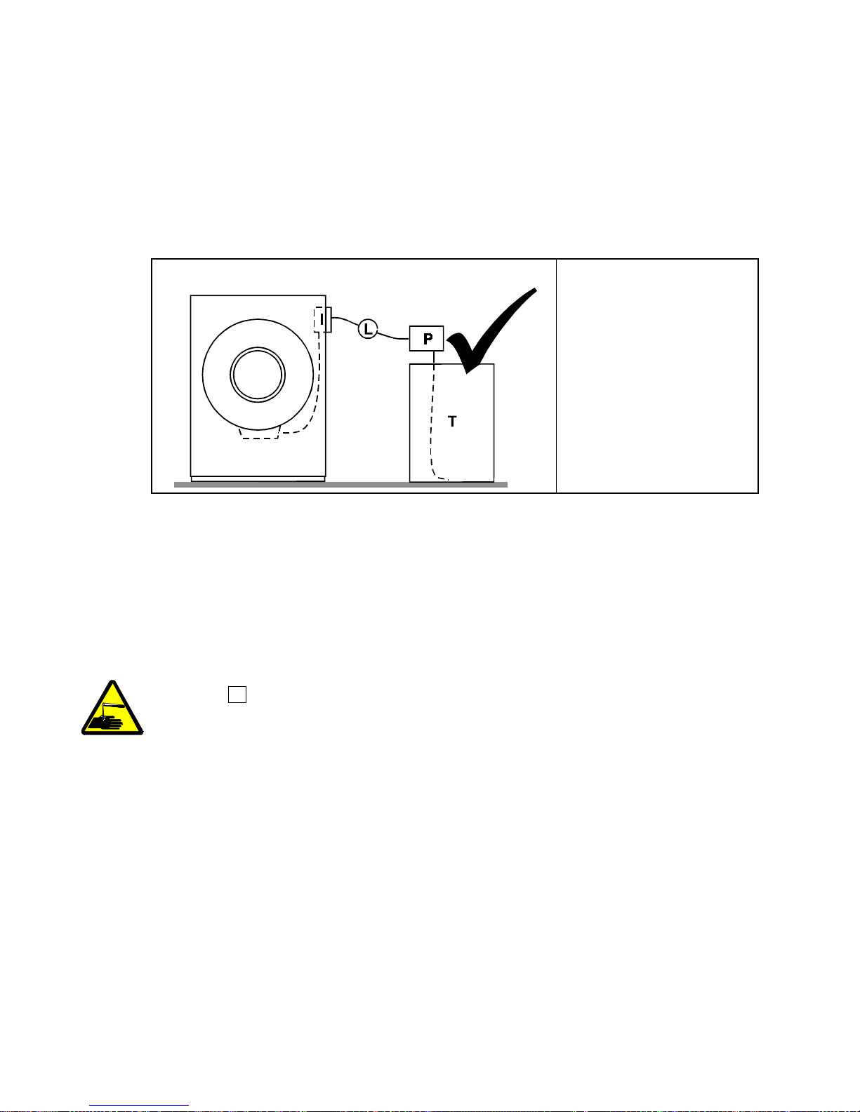
3.4.
Dribbling: Locate the entire chemical line below the machine inlet.
—
Assuming the chemical system does not retain any line pressure and that the pump provides
positive closure when the system is off, locate the entire chemical delivery line below the level of
the chemical inlet. An example of this is shown in Figure 4.
Figure 4:
Locating a Pumped Chemical System With Positive
Closure To Protect Against Machine Damage
Example of Correct Placement Legend
Chemical inlet on
I.
machine
Chemical delivery line
L.
Pump with positive
P.
closure when system is
off
Chemical tank
T.
4.
Guarding Against Leaks
All personnel who may work with the chemical system (e.g., chemical system manufacturer,
chemical system supplier, chemical supplier, operator, maintenance personnel) should be vigilant
in observing for leaks in the system. When connecting, or reconnecting chemical lines, whether at
installation, after taking samples, or when replacing components, at a minimum ensure that:
1. the proper components are used,
2. all connections are the proper fit, and
3. all components are securely connected.
CAUTION 2 : Injury and Damage Hazards
may be corrosive or toxic. Such chemicals can injure personnel and damage equipment.
• Use care when connecting chemical lines.
• Inspect regularly for leaks.
—Chemicals leaking from a chemical system
— End of BIWUUI03 —
PELLERIN MILNOR CORPORATION

Section 1
Service and Maintenance
MSSM0201CE/2004046V
ÈLUBRICATION AND PREVENTIVE MAINTENANCE
FOR HYDRO-CUSHION® MACHINES
ÊGeneral Requirements
Maintenance procedures require:
• A hand operated grease gun.
• The correct lubricants (see “LUBRICANTS FOR MILNOR MACHINES,” in the Table of Contents).
ÊLubricant Requirements
To achieve the optimum performance and service life from the Milnor® machine and as a warranty require-
ment, the machine must be lubricated in strict accordance with the instructions in this section.
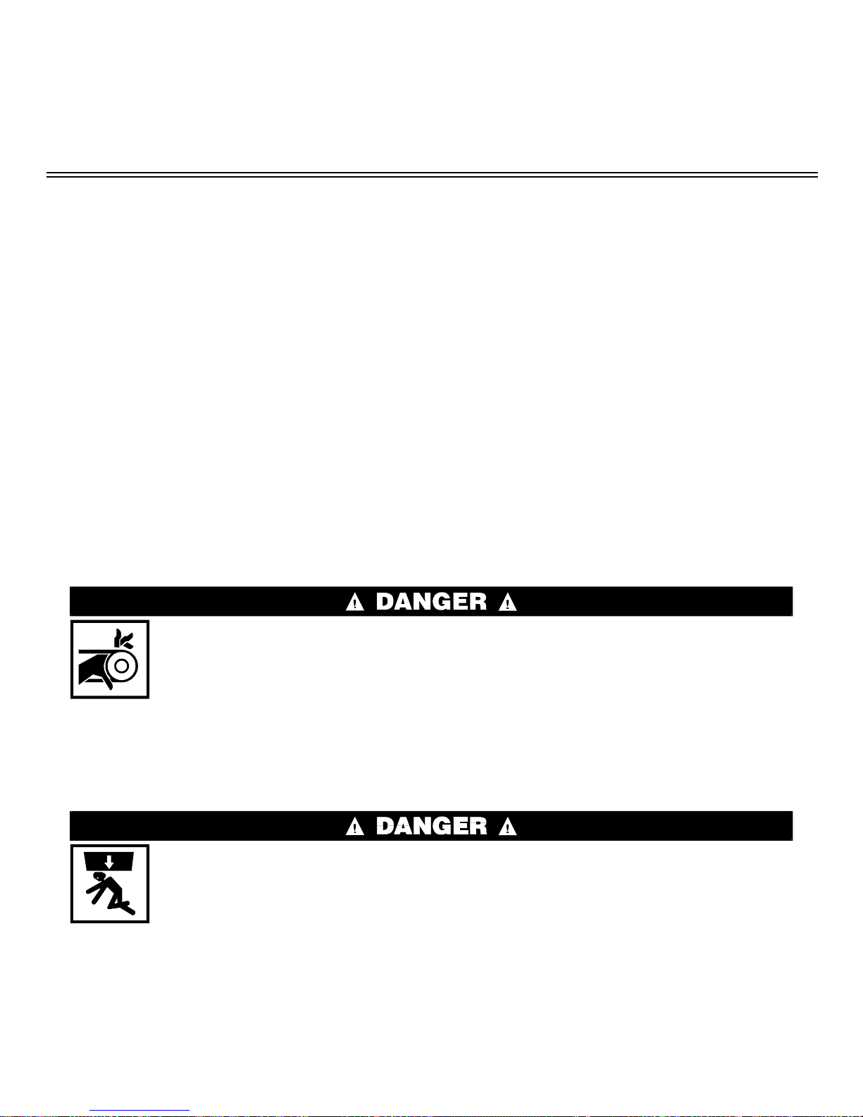
ENTANGLE AND CRUSH HAZARD—Belts and pulleys can entangle and crush
body parts.
☞ Lock OFF and tag out power at the wall disconnect before servicing, except
where specifical ly in structed otherwise in this sect ion.
☞ Insure belt and pulley guards are in place during service procedures.
☞ Permit only qualified maintenance personnel to perform these procedures.
CRUSH/SEVER HAZARD—Tilting mechanism can crush or sever parts of your
body caught in them.
☞ Install the safety stands before performing maintenance under a tilted ma-
chine.
☞ NEVER test or operate (manually or automatically) any machine function
with any portion of a person’s body under the tilted machine—even if the
safety stands are ins tal led.
 Loading...