

Milnor 60044WP3 Service Manual
Published Manual Number/ECN: MPP60WE3AE/2001044N
• Publishing System: TPAS
• Access date: 01/23/2001
• Document ECN's: Exact
Service—
60044WP3 Washer-Extractors
PELLERIN MILNOR CORPORATION POST OFFICE BOX 400, KENNER, LOUISIANA 70063-0400, U.S.A.

Please Read
About the Manual Identifying Information on the Cover
The front cover displays pertinent identifying information for this manual. Most important, are
the published manual number (part number) /ECN (date code). Generally, when a replacement
manual is furnished, it will have the same published manual number, but the latest available ECN.
This provides the user with the latest information applicable to his machine. Similarly all
documents comprising the manual will be the latest available as of the date the manual was
printed, even though older ECN dates for those documents may be listed in the table of
contents.
When communicating with the Milnor factory regarding this manual, please also provide the
other identifying information shown on the cover, including the publishing system, access date,
and whether the document ECN’s are the latest available or exact.
References to Yellow Troubleshooting Pages
This manual may contain references to “yellow pages.” Although the pages containing
troubleshooting procedures are no longer printed on yellow paper, troubleshooting instructions, if
any, will be contained in the easily located “Troubleshooting” chapter or section. See the table of
contents.
Trademarks of Pellerin Milnor Corporation
The following, some of which may be used in this manual, are trademarks of Pellerin Milnor
Corporation:
®
Ampsaver
Autolint
®
Auto-Purge
Autovac E-P OneTouch® Mildata
®
CBW
Dye-Extractor® Gear Guardian
Dyextractor® Hands-Off
®
E-P Express® Hydro-Cushion
E-P Plus
®
®
®
®
®
®
Milnet
Milnor
®
Staph-Guard
System 4
Miltrac System 7
Miltron Totaltrol
®
®
®
®
Comments and Suggestions
Help us to improve this manual by sending your comments to:
Pellerin Milnor Corporation
Attn: Technical Publications
P. O. Box 400
Kenner, LA 70063-0400
Fax: (504) 469-1849

Table of Contents
for MPP60WE3AE/2001044N
60044WP3 Washer-Extractors
Page Description Document/ECN
1 About This Manual MHPHYDROAE/9541AV
3 Warranty BMP720097/92732A
4 How to Order Parts BMP720097R/72332A
5 Installation and Service Safety for Suspended
Washer-Extractors and Centrifugal Extractors MSINA405AE/2000215V
10 About the Forces Transmitted by Milnor Washer-Extractors BIWUUI02/20001108
12 Glossary of Tag Illustrations - Suspended Washer-
Extractors MSIUPUTGAE/9808AV
17 Section 1: Service and Maintenance
18 Lubrication and Preventive Maintenance for Hydro-
Cushion Machines MSSM0201CE/9840AV
29 Lubricants for Milnor Machines MSSM0132AE/9903AV
30 Baldor Motor Maintenance MSSM0274AE/9731AV
34 Lubrication Points for 42" Hydro-Cushion Washer-Extractor BMP701174/2069371A
35 Lubrication Points for 42" Hydro-Cushion Washer-Extractor BMP701174R/2069367
36 Lubrication Chart BMP701226/74113A
37 Lubrication Chart BMP701226R/74113A
38 Fastener Torque Requirements MSSM0101CE/9906AV
57 Section 2: Shell and Door Assemblies
58 Door Seal Replacement on Rapid Load Models MSSMA413AE/8530BV
62 Shell Door Assembly BMP700402/70316
63 Parts List - Shell Door Assembly BMP700402R/70121V
64 Cylinder Door Installation - 6036 & 6044 3-Pocket
Staph-Guard & Hydrocushion BMP970080/97402V
65 Cylinder Door Assembly - 6036 & 6044 3-Pocket
Staph-Guard & Hydrocushion BMP970081/97402V
67 Interlock Plunger Assembly BMP700630/94087V
68 60" WE3 & SG3 Door Assembly BMP800183/80323B
69 Parts List - Door Assembly, 60" SG3, WE3 BMP800183R/98301V
71 Section 3: Drive Assemblies
72 Drive Base Components on Hydro-Cushion Machines MSSMA407BE/85047V
82 Jackshaft Bearing Assembly - 5238, 6036, 6044,
6442 & 7244 BMP820109/89253C
83 Parts List - Jackshaft Bearing Assembly (52, 60, 64, 72) BMP820109R/89253A
85 Drive Assembly - 6036WE2, WE3 & 6044WE2, WE3 BMP840021/91107D
86 Parts List - Drive Assembly, 60036 & 60044 WE2/WE3 BMP840021R/98446V
87 Reducer Air Seal BMP700392/93376V
88 Autospot Drive Assembly BMP701411/2000133V
90 Air Operated Autospot Assembly - 60044WP2/WP3
and 72044WP2/WP3 BMP710043/96216V

Table of Contents, cont.
Page Description Document/ECN
91 Sensing Unit = Airop Autospot BMP710042/76143D
92 Parts List - Sensing Unit, Airop Autospot BMP710042R/85353A
93 Brake Installation - 6036 & 6044 BMP760001/76022B
94 Parts List - Brake Installation (60WED) BMP760001R/85341A
95 Centrifugal Switch Assembly BMP701195/2000242V
97 Centrifugal Switch Operation BMP701196/81271A
98 Brake Assembly - 60044 & 72044 WP2/WP3 BMP710022/99512V
99 V-Belt Tension Adjustments for 48", 52", 60"
and 72" Washer-Extractors MSSMA405AE/8737BV
103 Section 4: Bearing Assemblies
104 Main Bearing and Seal Replacement for Divided
Cylinder Machines MSSM0303AE/8451BV
114 Main Bearing Assembly - 60036, 60044 & 72044
WE2, WE3, SG2, SG3 & DA3 BMP840039/84336D
115 Parts List - Main Bearing Assembly BMP840039R/96142V
117 Section 5: Frame, Pivots and Suspension
118 Hold Down Adjustments 60" & 72" Rapid Load
& Staph-Guard Washer-Extractors BMP701672/71051
119 Hold Down Adjustments - 60" & 72" Rapid Load
and Staph-Guard BMP701672R/71051
120 Suspension Adjustments for Divided Cylinder Machines MSSM0302AE/8414BV
126 Suspension Cylinder Assemblies - 42031, 42044,
52038, 60044 & 72044 BMP701408/2000133V
128 Parts List - Suspension Cylinder Assembly BMP701408R/97266V
129 Suspension Cylinder Locations BMP701235/2000133V
130 Push Down Assembly BMP701671/70526
131 Parts List - Push Down Assembly BMP701671R/70526
133 Section 6: Control and Sensing Assemblies
134 Vibration Safety Switch Adjustments MSSMA408BE/9273BV
136 Vibration Switch Assembly BMP700613/83211A
137 Parts List - Vibration Switch Assembly BMP700613R/83211A
138 Maintenance - Vib Safety Switch BMP750047/81307A
139 Section 7: Chemical Supply Devices
140 Rules for the Field Installation of Pumped-Type
Liquid Supply Systems MSSM0213AE/89457V
142 Supply Injector - 6036, 6044 & 5238 BMP700940/97287V
145 Section 8: Water and Steam Piping and
Assemblies
146 Ball Valve Water Inlet Assembly BMP701539/89113D
147 Parts List - Water Inlet Assembly BMP701539R/71521A
148 Universal Actuators & Mounting Hardware for
Watts Ball Valves - New Pivot BMP920005/96067V
151 Watts Ball Valves and Repair Kits BMP920007/96066V

Table of Contents, cont.
Page Description Document/ECN
153 Pressure Regulators BMP900031/96081V
155 Water Level Float Chamber Assembly BMP810111/83404C
156 Parts List - Water Level Float Chamber Assembly BMP810111R/89256A
158 Water Level Switch Assembly BMP800186/93192V
159 8" & 10" Stainless Dump Valve BMP780095/2000133V
160 Burket Steam Valve BMP800020/96066V
161 Steam Sparger Assemblies BMP900001/96132V
163 Section 9: Pneumatic Piping and Assemblies
164 3 Way Pilot Valves BMP900032/91182V
165 Asco 3-way Solenoid Valves BMP701359/97086V
167 ½" ASCO N.C. Valve Assembly BMP701394/71463A
168 Parts List - ½" ASCO N.C. Valve BMP701394R/81377A
169 Universal Airvalve Box Assembly BMP780088/83457C
170 Parts List - Universal Airvalve Box BMP780088R/93046N
172 Air Valves & Mounting Hardware BMP780087/83457B
173 Parts List - Air Valves & Mounting Hardware BMP780087R/83457A
175 Quick Exhaust Valves BMP701406/98296V
177 Air Cylinder Assemblies BMP830078/2000133V
180 Air Cylinders for 2"Watts Ball Valves BMP920006/2000133V


MHPHYDROAE/9541AV (1 of 1)
ÈABOUT THIS MANUAL
ËScope—This instruction manual is intended to provide preventive maintenance, service procedures, an d
mechanical parts identification for your machine. See the safety manual for safety instructions before installing,
servicing, or operating this machine. See the installation guide for facility requirements, installation instructions,
and assembly instructions. See the operator guide for operator instructions. See the reference manual for programming, operating, and troubleshooting instructions. See the schematic manual for electrical parts identification and
electrical troubleshooting.
ËManual Number/Date Code (When To Discard or Save)—The manual number/date code is lo-
cated on the inside front cover, upper right corner just above the manual name. Whenever the manual is reprinted
with new information, part of this number changes. If the date code after the “/” changes, the new version applies
to all machines covered by the old version, but is improved— thus the old version can be discarded. If the
manual number before the “/” changes, the new manual covers only new machines. Example: Discard MAT-
MODELAE/8739CV when MATMODELAE/8739DV is received (minor improvements). Also, discard MATMODELAE/8739DV when MATMODELAE/8746AV is received (major improvements). But keep
MATMODELAE/8746FV when MATMODELBE/8815AV is received, since the new manual no longer applies to
machines originally shipped with the old manual.
ËDocuments and Change Bars —The individual documents comprising this manual use the same revision
criteria as the manual. Text documents also display change bars. Example: When section MSOP0599AE/9135BV
becomes MSOP0599AE/9135CV, change bars with the letter “C” appear next to all changes for this revision. For
a major rewrite (e.g., MSOP0599AE/9226AV), all change bars are deleted.
ËTrademarks of Pellerin Milnor Corporation—The following, some of which may be used in this pub-
lication, are trademarks of Pellerin Milnor Corporation:
Ampsaver
®
Autolint
®
Auto-Purge
®
Autovac
CBW
®
Dye-Extractor
®
Dyextractor
®
E-P Plus
®
Gear Guardian
®
Hands-Off
®
Hydro-Cushion
®
Mildata
®
Milnet
®
Milnor
®
Miltrac
Miltron
Staph-Guard
®
System 4
®
System 7
®
Totaltrol
®
ËFor Assistance—Please call:
Pellerin Milnor Corporation
Attn: Service Department
P. O. Box 400
Kenner, LA 70063-0400
Phone: (504) 467-9591
Fax: (504) 467-9777


3(//(5,10,/125&25325$7,21
/,0,7('67$1'$5':$55$17<
We warrant to the original purchaser that MILNOR machines including electronic
hardware/software (hereafter referred to as “equipment”), will be free from defects in material
and workmanship for a period of one year from the date of shipment from our factory with no
operating hour limitation. This warranty is contingent upon the equipment being installed,
operated and serviced as specified in the operating manual supplied with the equipment, and
operated under normal conditions by competent operators.
Providing we receive written notification of a warranted defect within 30 days of its discovery,
we will – at our option – repair or replace the defective part or parts, FOB our factory. We
retain the right to require inspection of the parts claimed defective in our factory prior to
repairing or replacing same. We will not be responsible, or in any way liable, for unauthorized
repairs or service to our equipment, and this warranty shall be void if the equipment is repaired
or altered in any way without MILNOR’s written consent.
Parts which require routine replacement due to normal wear – such as gaskets, contact points,
brake and clutch linings and similar parts – are not covered by this warranty, nor are parts
damaged by exposure to weather or to chemicals.
We reserve the right to make changes in the design and/or construction of our equipment
(including purchased components) without obligation to change any equipment previously
supplied.
ANY SALE OR FURNISHING OF ANY EQUIPMENT BY MILNOR IS MADE ONLY UPON
THE EXPRESS UNDERSTANDING THAT MILNOR MAKES NO EXPRESSED OR IMPLIED
WARRANTIES OF MERCHANTABILITY OR FITNESS FOR ANY PARTICULAR USE OR
PURPOSE. MILNOR WILL NOT BE RESPONSIBLE FOR ANY COSTS OR DAMAGES
ACTUALLY INCURRED OR REQUIRED AS A RESULT OF: THE FAILURE OF ANY OTHER
PERSON OR ENTITY TO PERFORM ITS RESPONSIBILITIES, FIRE OR OTHER HAZARD,
ACCIDENT, IMPROPER STORAGE, MISUSE, NEGLECT, POWER OR ENVIRONMENTAL
CONTROL MALFUNCTIONS, DAMAGE FROM LIQUIDS, OR ANY OTHER CAUSE BEYOND
THE NORMAL RANGE OF USE. REGARDLESS OF HOW CAUSED, IN NO EVENT SHALL
MILNOR BE LIABLE FOR SPECIAL, INDIRECT, PUNITIVE, LIQUIDATED, OR
CONSEQUENTIAL COSTS OR DAMAGES, OR ANY COSTS OR DAMAGES WHATSOEVER
WHICH EXCEED THE PRICE PAID TO MILNOR FOR THE EQUIPMENT IT SELLS OR
FURNISHES.
WE NEITHER ASSUME, NOR AUTHORIZE ANY EMPLOYEE OR OTHER PERSON TO
ASSUME FOR US, ANY OTHER RESPONSIBILITY AND/OR LIABILITY IN CONNECTION
WITH THE SALE OR FURNISHING OF OUR EQUIPMENT TO ANY BUYER.
BMP720097
92732A

How to order repair parts
Repair parts may be ordered either from the authorized dealer who sold you this
machine, or directly from the MILNOR factory. In most cases, your dealer will
have these parts in stock.
When ordering parts, please be sure to give us the following in formation:
1. Model and serial number of the machine for which the parts are required
2. Part number
3. Name of the part
4. Quantity needed
5. Method of shipment des ired
6. In correspondence regarding motors or electrical controls, please include all
nameplate data, including wiring diagram number and the make or
manufacturer of the motor or controls.
All parts will be shipped C.O.D. transportation charges collect on ly.
Please read this manual
It is strongly recommended that you read the installation and operating manual
before attempting to install or operate your machine. We suggest that this manual
be kept in your business office so that it will not become lo st.
PELLERIN MILNOR CORPORATION
32%2;.(11(5/$ 86$
FAX: Administration 504/468-9307, Engineering 504/469-1849, Service 504/469-9777
BMP720097R
72332A

MSINA405AE/2000215V
ÈINSTALLATION AND SERVICE SAFETY FOR SUSPENDED
WASHER-EXTRACTORS AND CENTRIFUGAL EXTRACTORS
ÊGeneral Safety Requirements
(specific warnings, next page and throughout manual)
Incorrect installation, neglected preventive maintenance, abuse, and/or improper repairs or changes to the
machine can cause unsafe operation and personal injuries, such as multiple fractures, amputations, or death. The
owner or his selected representative ( owner/user) is responsible for underst anding and ensuring the proper operation
and maintenance of the machine. The owner/user must familiarize himself with the contents of all machine instruction manuals. The owner/user should direct any questions about these instructions to a Milnor® dealer or the Milnor® Service department.
Most regulatory authorities (including OSHA in the USA) hold the owner/user ultimately responsible for
maintaining a safe working environment. Therefore, the owner/user must do the following:
• recognize all foreseeable safety hazards within his facility and take actions to protect his personnel,
equipment, and facility
• require that personnel are familiar with all functional and safety aspects of the machine
• ensure safety devices installed on the machine are in place and properly maintained
• ensure all machine parts and assemblies are properly maintained.
ËLaundry Facility
—Provide a supporting floor that is strong and rigid enough to support--with a reasonable
safety factor and without undue or objectionable deflection--the weight of the fully loaded machine and the forces
transmitted by it during operation. (For washer-extractors, see “ABOUT THE FORCES TRANSMITTED BY MILNOR® WASHER-EXTRACTORS.”) Provide sufficient clearance for machine movement. Provide any safety
guards, fences, restraints, devices, and verbal and/or posted restrictions necessary to prevent personnel, machines,
or other moving machinery from accessing the machine or its path. Provide adequate ventilation to carry away heat
and vapors. Ensure service connections to installed machines meet local and national safet y standards, especially
regarding the electrical disconnect (see the National Electric Code). Prom inently post s afety informati on, including
signs showing the source of electrical disconnect.
ËPersonnel
—Inform personnel about hazard avoidance and the importance of care and common sense. Provide
personnel with the safety and operating instructions that apply to them. Verify that pers onnel use proper safety and
operating procedures. Verify that personnel understand and abide by point-of-hazard tags on the machine and procedure-specific precautions in the instruction manuals.
ËSafety Devices
—Ensure that no one eliminates or disables any safety device on t he machine or in this facilit y.
Do not allow machine to be used with any missing guard or cover. Service any failing or malfunctioning device
before operating the machine.
ËMaintenance
—Ensure the machine is inspected and serviced in accordance with the norms of good practice and
with the preventive maintenance schedule. Replace belts, pulleys, brake shoes/disks, clutch plates/tires, rollers,
seals, alignment guides, etc. before they are severely worn. Immediately investigate any evidence of impending
failure and make needed repairs (e.g., cylinder, shell, or frame cracks; drive components such as motors, gear boxes,
bearings, etc., whining, grinding, smoking, or becoming abnormally hot; bending or cracking of cylinder, shell,
frame, etc.; leaking seals, hoses, valves, etc.) Do not permit service or maintenance by unqualified personnel.
READ BEFORE INSTALLING MACHINE!
ÊHazards During Installation
ELECTROCUTION HAZARD—Contact with high voltages can kill or seriously
injure you.
☞ All electrical connections must be made by a competent electrician.
EQUIPMENT DAMAGE HAZARD—Machine can be damaged if shipping restraints are improperly utilized. These include various bolts, brackets, and
safety stands (painted red), brake blocks and the vibration safety switch (tie
wrapped).
☞ DO NOT remove shipping restraints until installation is complete.
☞ DO remove all shipping restraints before operating machine.
ÊHazards During Service and Maintenance
ELECTROCUTION HAZARD—High voltage is present inside electric boxes, motors and many other components. Power switches on machine control panels
disable only control circuit power in certain boxes. You can be killed or seriously injured on contact with high voltage.
☞ Lock OFF and tag out power at the wall di sconnect before ser vici ng, except w her e spe-
cifically instructed otherwise in this manual.
ENTANGLE AND CRUSH HAZARD—Belts and pulleys can entangle and crush
body parts.
☞ Lock OFF and tag out power at the wall disconnect before servicing, except
where specifical ly instr ucte d otherwis e in this manua l.
☞ Insure belt guards are in place during service procedures.
MULTIPLE HAZARDS—Failure to maintain machine in proper working order can result in
fatal or serious injury to operators and/or damage to property. DO NOT permit operation
under any of the following circumstances:
☞ Malfunctioning door interlock mechanism.
☞ Malfunctioning limit switches.
☞ Malfunctioning two hand inching.
☞ Any evidence of cylinder damage.
☞ Missing or removed guards, covers, or side panels.
☞ Malfunctioning tilting components, including but not limited to safety limit switches,
electrical interlocks, and operator controls.
☞ If any of these conditions occur:
• The machine makes a sound like skidding automobile tires as it comes out of extract.
• The wash or drain clutch does not disengage or it reengages during extract.
• V-belt s jum p off at the start of, during, or at the end of extract.
• A strange whining sound occurs at any time during extract.
BURN HAZARD — Machines equipped with heat exchangers and their associated piping may be hot enough to burn body parts on contact.
☞ Provide safety guards, fences, restraints, or covers as required to isolate hot
surfaces.
ÊAdditional Hazards During Tilting Machine Maintenance
CRUSH/SEVER HAZARD—Tilting mechanisms can crush or sever parts of your
body caught in them.
☞ Install the safety stands before performing maintenance under a tilted ma-
chine.
☞ NEVER test or operate (manually or automatically) any machine function
with any portion of a person’s body under the tilted machine—even if the
safety stands are ins tal led.
CRUSH/SEVER HAZARD—Tilting machines with tilt wheels/cradles may lunge forward or rearward and even fall ove r if the tilt wheels at the non-tilted end are r aised
out of their cradles—killing/ injuri ng personnel and/or damaging property.
☞ NEVER manually tilt (lift) both ends of the machine at the same time. One end must
always be seated in it s cradle.
☞ ALWAYS visually inspect the tilt wheels to be sure they are all fully seated in their cra-
dles before each manual tilt up.
☞ Hydraulic valve manual operation must be done by trained competent maintenance per-
sonnel who thoroughly understand the system and all the consequences of manual
operations.
☞ ALWAYS understand beforehand all the consequences of manually operating hydraul ic
valves.
☞ NEVER permit operation with malfunctioning tilt limit switches.
NOTE: Shipping brackets, (not shown
here) are also painted red. These may
be retained in the event the machine
must be moved.
Safety Stands or Brackets
Safety Stands or Brackets
These stands or brackets, painted red
and shown to the right, must be retained,
and used to support the machine during
servicing.
Read all safety instructions before performing maintenance.
Tall safety stands
Tall safety stands
Short safety stands
48032, 48036, 52038, and 72044
(dual pivot tilting washer-extractor models)
All except J2N models
64040, 64042, 64046, 72046, 72058 and 72075
(single pivot tilting washer-extractor models)
J2N models
Centrifugal extractor models
Short safety stands
48040
(dual pivot tilting washer-extractor model)

About the Forces Transmitted by Milnor® Washer-extractors
2
8
8
8
U
About the Forces Transmitted by Milnor
Washer-extractors
During washing and extracting, all washer-extractors transmit both static and dynamic
(cyclic) forces to the floor, foundation, or any other supporting structure. During washing, the
impact of the goods as they drop imparts forces which are quite difficult to quantify. Size for size,
both rigid and flexibly-mounted machines transmit approximately the same forces during
washing. During extracting, rigid machines transmit forces up to 30 times greater than equivalent
flexibly-mounted models. The actual magnitude of these forces vary according to several factors:
• machine size,
• final extraction speed,
• amount, condition, and type of goods being processed,
• the liquor level and chemical conditions in the bath preceding extraction, and
• other miscellaneous factors.
Estimates of the maximum force normally encountered are available for each Milnor
and size upon request. Floor or foundation sizes shown on any Milnor
on-grade situations based only on previous experience without implying any warranty, obligation,
or responsibility on our part.
1.
Rigid Machines
Size for size, rigid washer-extractors naturally require a stronger, more rigid floor,
foundation, or other supporting structure than flexibly-mounted models. If the supporting soil
under the slab is itself strong and rigid enough and has not subsided to leave the floor slab
suspended without support, on grade installations can often be made directly to an existing floor
slab if it has enough strength and rigidity to safely withstand our published forces without
transmitting undue vibration. If the subsoil has subsided, or if the floor slab itself has insufficient
strength and rigidity, a deeper foundation, poured as to become monolithic with the floor slab,
may be required. Support pilings may even be required if the subsoil itself is “springy” (i.e., if its
resonant frequency is near the operating speed of the machine). Above-grade installations of rigid
machines also require a sufficiently strong and rigid floor or other supporting structure as
described below.
®
Document..................... BIWUUI0
Specified Date.................2000110
As-of Date.......................2000110
Access Date..................... 2000110
Applicability...........................WU
®
®
document are only for
model
2.
Flexibly-mounted Machines
Size for size, flexibly-mounted machines generally do not require as strong a floor,
foundation, or other supporting structure as do rigid machines. However, a floor or other
supporting structure having sufficient strength and rigidity, as described in section 3, is
nonetheless vitally important for these models as well.
3.
How Strong and Rigid?
Many building codes in the U.S.A. specify that laundry floors must have a minimum live
load capacity of 150 pounds per square foot (732 kilograms per square meter). However, even
compliance with this or any other standard does not necessarily guarantee sufficient rigidity. In
any event, it is the sole responsibility of the owner/user to assure that the floor and/or any other
supporting structure exceeds not only all applicable building codes, but also that the floor and/or
any other supporting structure for each washer-extractor or group of washer-extractors actually
has sufficient strength and rigidity, plus a reasonable factor of safety for both, to support the
weight of all the fully loaded machine(s) including the weight of the water and goods, and
including the published 360º rotating sinusoidal RMS forces that are transmitted by the
machine(s). Moreover, the floor, foundation, or other supporting structure must have sufficient
rigidity (i.e., a natural or resonant frequency many times greater than the machine speed with a
reasonable factor of safety); oth erwise, the m enti oned 360º ro ta ting sinuso ida l RMS forces can be
multiplied and magnified many times. It is especially important to consider all potential vibration
problems that might occur due to all possible combinations of forcing frequencies (rotating
speeds) of the machine(s) compared to the natural frequencies of the floor and/or any other
supporting structure(s). A qualified soil and/or structural engineer must be engaged for this
purpose.
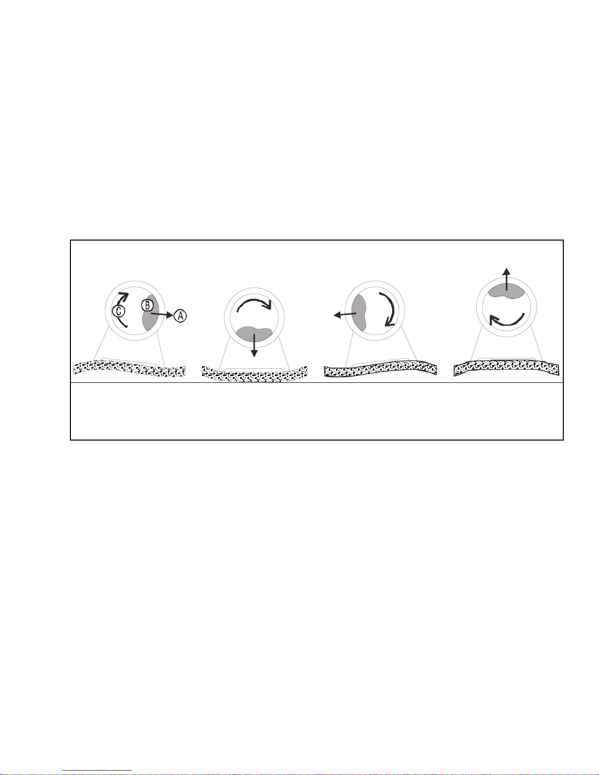
Figure 1: How Rotating Forces Act on the Foundation
Typical Machine
A.
Direction of force
B.
Load
C.
Rotation (Frequency = RPM / 60)
Figure 1 above is intended to depict both on-grade and above-grade installations and is
equally applicable to flexibly-mounted washer-extractors, as well as to rigid models installed
either directly on a floor slab or on a foundation poured integrally with the slab. Current machine
data is available from Milnor
have changed since last printed. It is the sole responsibility of every potential owner to obtain
written confirmation that any data furnished by Milnor
number(s) of the specific machines.
Legend
®
upon request. All data is subject to change without notice and may
®
applies for the model(s) and serial
— End of BIWUUI02 —
<B8D?DC604(''0E
7\_ccQbi_VDQW9\\ecdbQdY_^c±
Cec`U^TUTGQcXUb5hdbQSd_bc
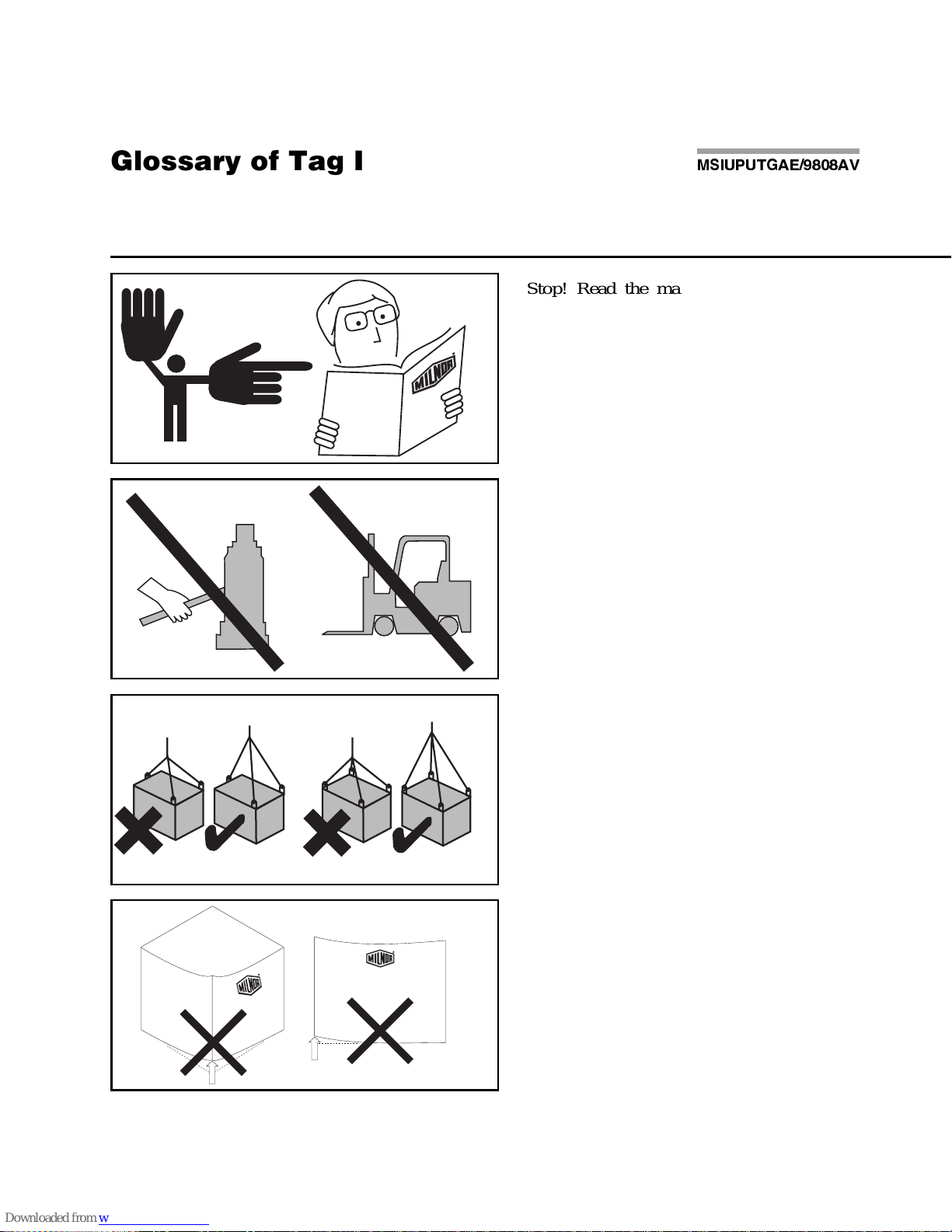
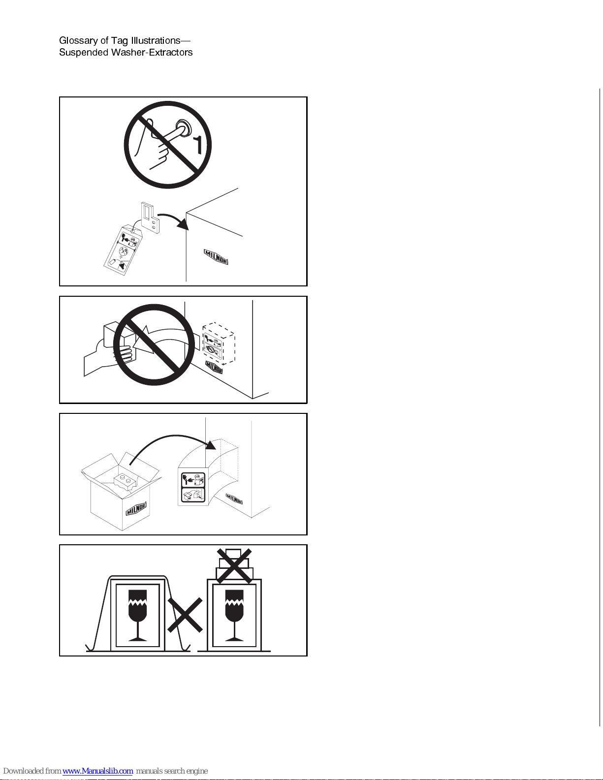
Illustration Explanation Illustration Explanation
Stop! Read the manual first for complete
instructions before continuing.
Do not jack the machine here.
Do not lift the machine here.
Use three point or four point lifting as
determined by the lifting eyes furnished. Rig
the load using lifting cables of sufficient size
and length to ensure cables are not
over-stressed.
Do not lift the machine from one corner or one
side edge.
Do not start this machine until the packing
materials, lifting brackets, etc. with this tag
attached or behind this panel are removed.
These materials are painted red. Safety stands
or brackets (also painted red) may be provided
with this machine. Do not discard safety
stands or brackets
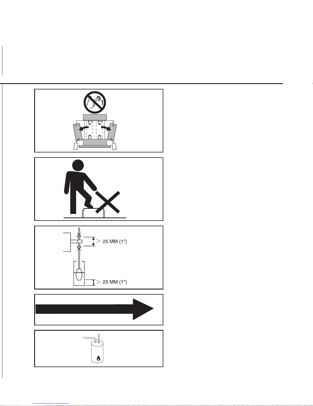
Do not step or stand on this machine part.
Maintain a 25 mm. (1") minimum clearance
between float clips. Set "low level" so that the
bottom of the float is always at least 25mm
(1") above the bottom of the float tube.
This motor or pump should rotate in the
direction of the arrow.
This is the hot water inlet.
Do not start this machine until the part with
this tag is installed on the machine.
Do not remove this component from the
machine.
Install the appropriate part here before
operating the machine.
Do not strap or chain over box
7\_ccQbi _V DQW 9\\ecdbQdY_^c±
Cec`U^TUT GQcXUb5hdbQSd_bc =C9E@ED715)( (1F " #
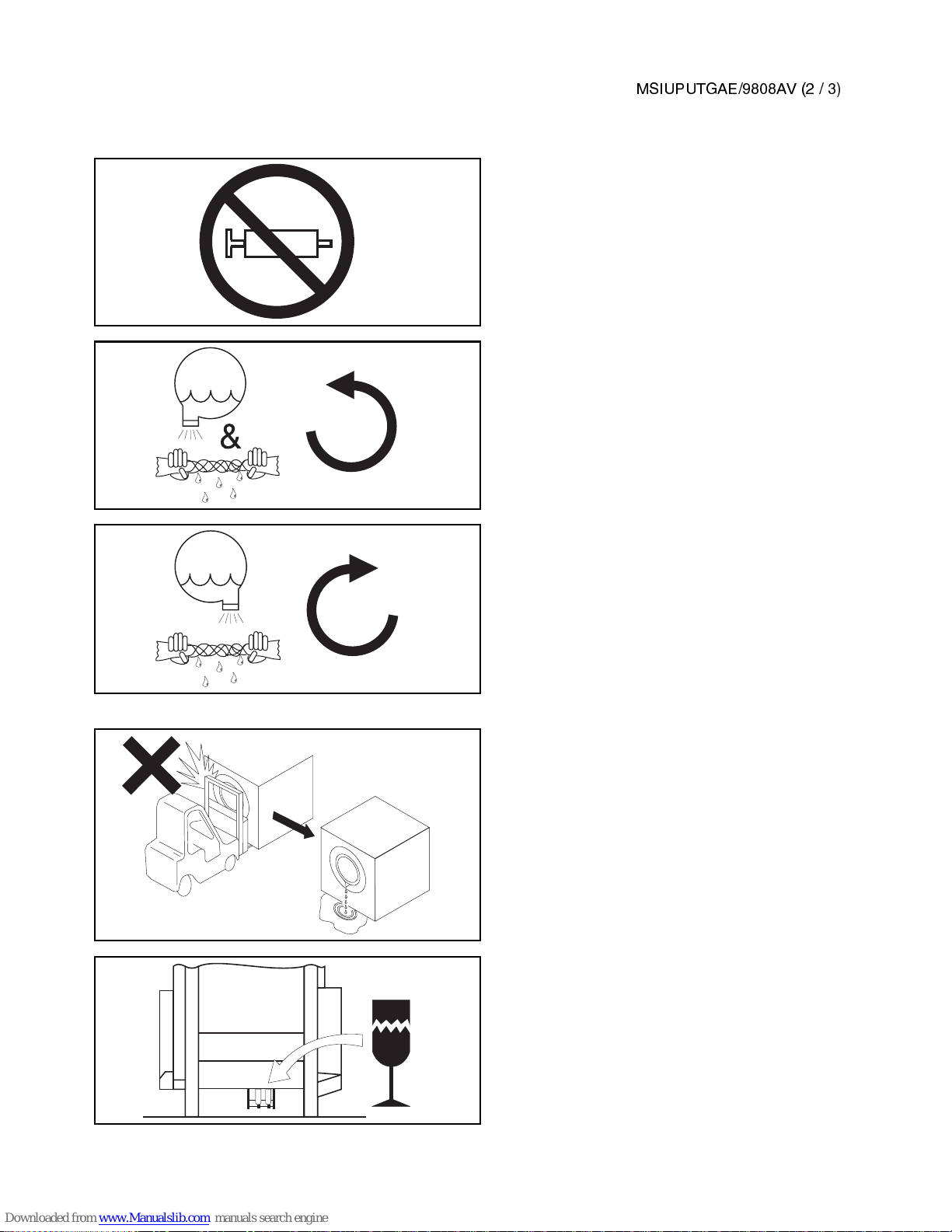
Do not pump grease here.
During drain and extract, the cylinder must
rotate counterclockwise when viewed from
here.
During drain and extract, the cylinder must
rotate clockwise when viewed from here.
Do not strike shell front of washer-extractors
during fork lifting. Striking shell front will
cause door to leak.
Brake assembly under machine is fragile.
Forklift blades should only be placed under
main structural beams
&
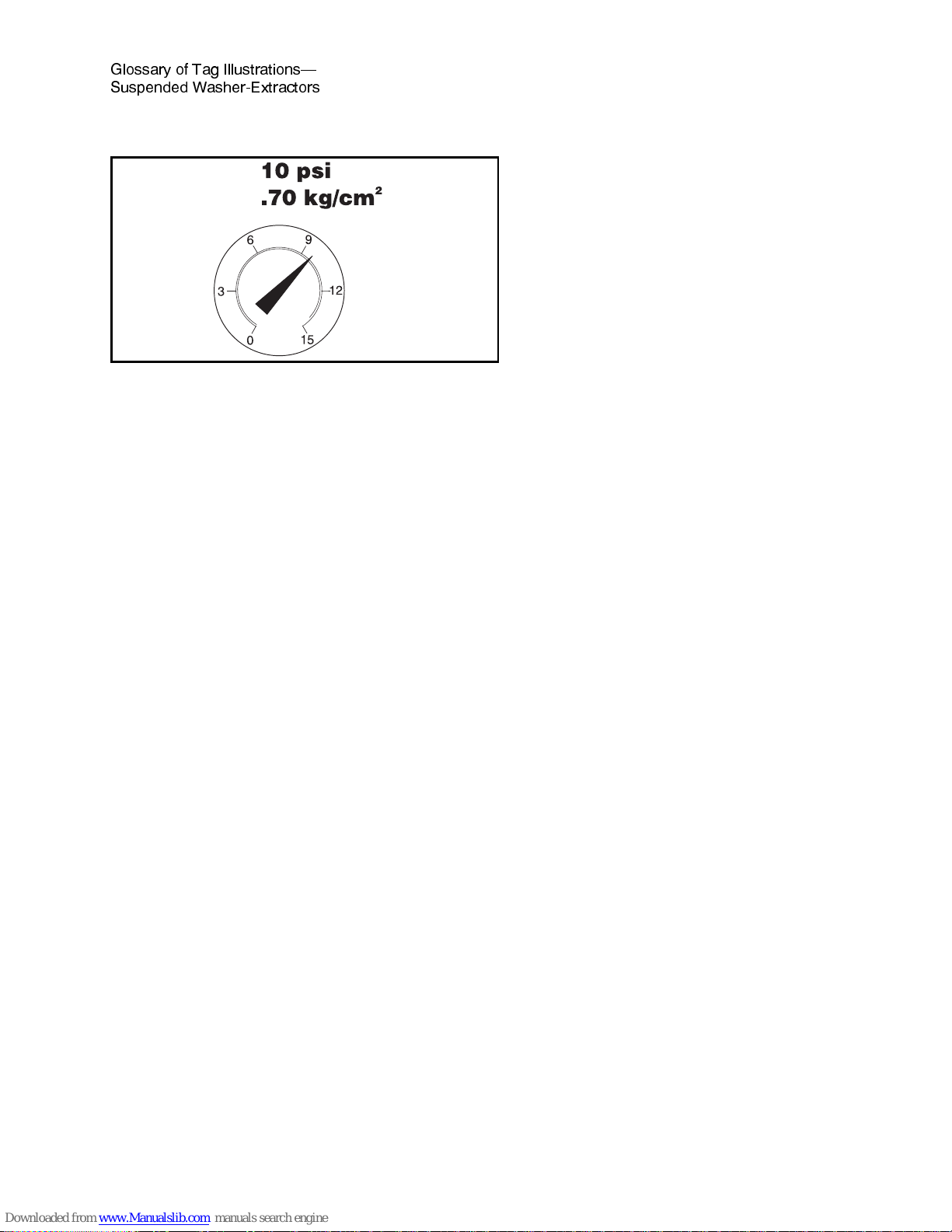
Set main bearing air pad gauge at 10 psi
(.70 kg/cm2), 64" and 72" ExN and JxN
models only.
Set disc brake air gauge at 10 psi
(.70 kg/cm2), 64" and 72" ExN and JxN
models only.
7\_ccQbi _V DQW 9\\ecdbQdY_^c±
Cec`U^TUT GQcXUb5hdbQSd_bc =C9E@ED715)( (1F # #

Section 1
Service and Maintenance
MSSM0201CE/9 84 0A V (1of 11)
ÈLUBRICATION AND PREVENTIVE MAINTENANCE
FOR HYDRO-CUSHION
®
MACHINES
ÊGeneral Requirements
Maintenance procedures require:
• A hand operated grease gun.
• The correct lubricants (see “LUBRICANTS FOR MILNOR MACHINES,” in the Table of Contents).
ÊLubricant Requirements
To achieve the optimum performance and service life from th e Milnor® machine and as a warranty require-
ment, the machine must be lubricated in strict accordance with the instructions in this section.
ENTANGLE AND CRUSH HAZARD—Belts and pulleys can entangle and crush
body parts.
☞ Lock OFF and tag out power at the wall disconnect before servicing, except
where specifically instructed otherwise in this section.
☞ Insure belt and pulley guards are in place during service procedures.
☞ Permit only qualified maintenance personnel to perform these procedures.
CRUSH/SEVER HAZARD—Tilting mechanism can crush or sever parts of your
body caught in them.
☞ Install the safety stands before performing maintenance under a tilted ma-
chine.
☞ NEVER test or operate (manually or automatically) any machine function
with any portion of a person’s body under the tilted machine—even if the
safety stands are inst al le d.

CRUSH/SEVER HAZARD—Tilting machines with tilt wheels/cradles may lunge
forward or rearward and even fall over if the tilt wheels at the non-tilted end are
raised out of their cradles—killing/injuring personnel and/or damaging property.
☞ NEVER manually tilt (lift) both ends of the machine at the same time. One end must
always be seated in it s cradle.
☞ ALWAYS visually inspect the tilt wheels to be sure they are all fully seated in their cra-
dles before each manual tilt up.
☞ Hydraulic valve manual operation must be done by trained competent maintenance per-
sonnel who thoroughly understand the system and all the consequences of manual
operations.
☞ ALWAYS understand beforehand all the consequences of manually operating hydraulic
valves.
☞ Never permit operation with malfunctioning tilt limit switches.
ÊCorrect Grease Gun Procedures
1. Do not use a pneumatic grease gun. Pump grease slowly, taking 10-15 seconds to complete each stroke.
A grease gun can build up extremely high pressure which will force seals out of position and cause them to
leak, even though both the seal and the bearing housing are equipped with spring loaded relief plugs.
2. Apply quantity of grease called for in the checklist. Over-lubrication can be as damaging as under-lubrica-
tion. Where quantities are stated in strokes, one stroke of the grease gun is assumed to provide .0624 fluid
ounces (1.77 grams) (by volume) of grease. Therefore, one fluid ounce (28.3 grams) of grease would be provided by 16 strokes of the grease gun. Determine the flow rate of your grease gun by pumping one ounce
into a calibrated container. If fewer than 16 strokes are required, all quantities in strokes in the chart should
be reduced accordingly, and if more than 16 strokes are required, the number of strokes should be increased.
Before starting lubrication, make sure your grease gun is working and that you get a full charge of
grease with every stroke.
3. Do not pump grease in until it oozes out of the spring loaded relief plugs. Plugs bleed out excess grease
and help prevent abnormal pressures from building up in the housing during operation (especially when the
machine is first commissioned and after each lubrication). Plugs will not protect against over-lubrication.
4. Do not over-lubricate motors. Over-lubrication of a motor can seriously damage it by forcing grease into
motor windings. Over-lubrication of the extract motor can force grease into the centrifugal switch causing it
to malfunction.
5. Do not allow grease to drip on the brake disk or clutch tire/drum during lubrication. This will reduce
the braking action considerably, and may permit the cylinder to creep while loading and unloading.
ÏDaily and Weekly Maintenance Items
Frequency Component Action
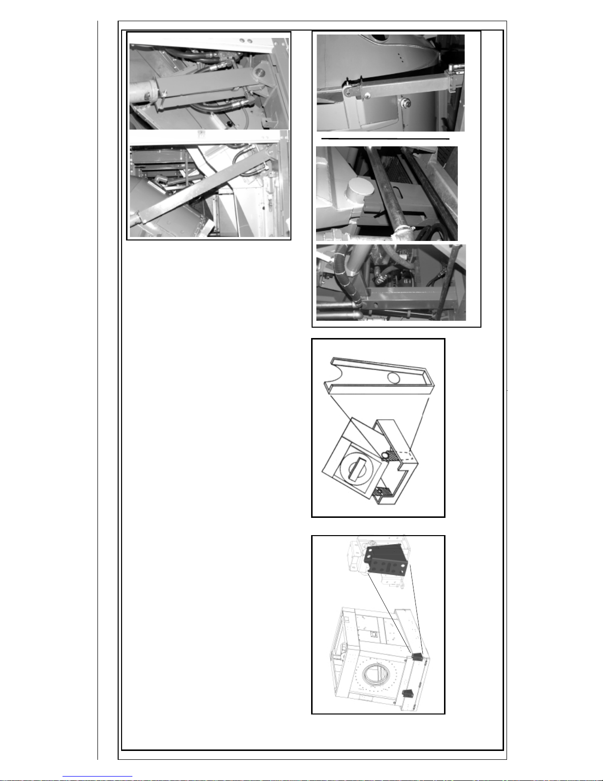
Daily Hydraulic Tilt System
(48", 52", and 72" Tilt machines)
• Reservoir
FIGURE 1 and NOTE 1
Check fluid with
machine not tilted
Hydro-Cushions
®
(all machines)
FIGURES 2 and 3
Check for leaks
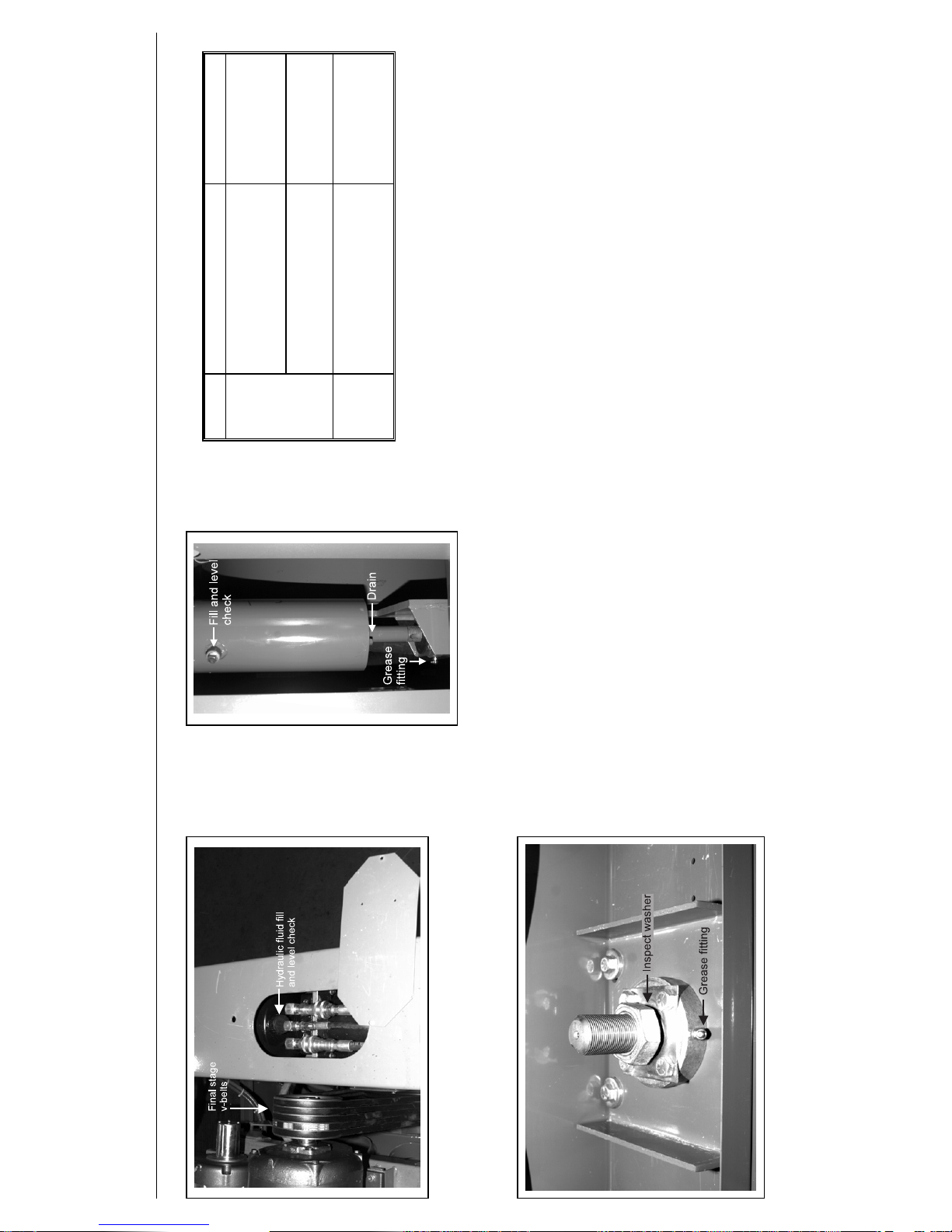
Weekly Final stage and other v-belts
(throughout all machines)
FIGURES 1 and 12
NOTES 2 and 3
Check for wear and
tension
NOTE 1: Tank should be approximately three-quarters full when the machine is not
tilted. Do not over-fill.
NOTE 2: V-belt instructions for the first week of operation
• After 24 hours operation (three eight hour days), tighten final stage v-belts.
• After 80 hours operation (ten eight hour days), tighten final stage v-belts
again.
• After 160 hours of operation (twenty eight hour days), tighten final stage
v-belts, and check all other v-belts and tighten if necessary.
NOTE 3: All v-belts are not alike. “Super” or “High Capacity” v-belts frequently have
considerably higher capacities than “Standard” belts. Sometimes, one brand of
v-belt is more suitable than another brand of v-belt, although both v-belts are
“interchangeable”. It is always best to purchase replacement belts from the
original manufacturer of the equipment. Purchasing exact replacements of the
original belts is the best way to assure belt life equal to the original set.
Occasionally, Milnor
®
will change a belt specification to improve belt life.
Belts purchased from Milnor
®
are as currently specified.
ÎFIGURE 1
(MSSM0201CE)
ÎHydraulic Fluid Reservoir Fill and Level Check Point
(located at rear of 48", 52", and 72" tilt machines only)
ÎFIGURE 2
(MSSM0201CE)
ÎTypical Hydro-Cushion
®
Maintenance Points
ÎFIGURE 3
(MSSM0201CE)
ÎTypical Upper Hydro-Cushion
®
Grease Fitting
LUBRICATION AND PREVENTIVE MAINTENANCE
FOR HYDRO-CUSHION MACHINES MSSM0201CE/9840AV (3 of 11)
ÏMonthly Maintenance Items
Frequency Component Action
Monthly
(see NOTE 4 )
All Divided cylinder and Staph-Guard
®
main bearing and seals
FIGURES 4 through 10, NOTES 5 and 6
• Each bearing grease
fitting
0.37 ounces (10.6 grams),
six strokes at two locations
• Each seal grease
fitting
0.12 ounces (3.54 grams),
two strokes at two locations
NOTE 4: Once a month or once every 200 operating hours, whichever occurs first.
NOTE 5: Main bearings and jackshaft bearings (if so equipped) are prepacked with
lubricant at the factory. Do not add grease for thirty days. During the first
month’s operation, some grease will ooze out of the automatic grease fittings
at the bottom of the housing(s). This is normal. These grease fittings allow
excess grease to escape, thus avoiding over-heating. This escaping lubricant
need not be replaced. Every time these bearings are lubricated, the surplus
grease will come out of the spring loaded relief fittings after a few hours
running time.
NOTE 6: Bearings can run hot enough to make it extremely uncomfortable for a
person to hold his hand on the bearing housing for more than a few seconds.
This is normal.
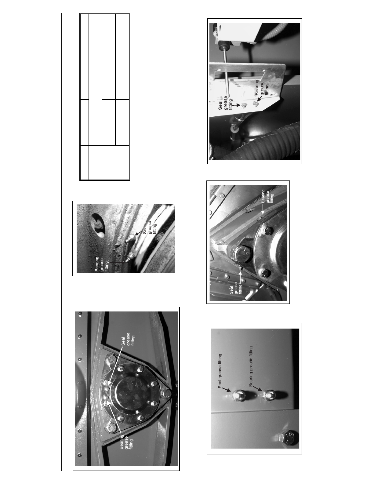
Ï
ÎFIGURE 4
(MSSM0201CE)
Î42" Divided Cylinder Front
Bearing and Seal Grease Fittings
ÎFIGURE 5
(MSSM0201CE)
Î42" Staph-Guard
®
Front and
Rear Bearing and Seal Grease
ÎFIGURE 6
(MSSM0201CE)
Î42" Divided Cylinder Rear Bearing
and Seal Grease Fittings
ÎFIGURE 7
(MSSM0201CE)
Î60" and 72" Divided Cylinder Front
Seal and Bearing Grease Fittings
ÎFIGURE 8
(MSSM0201CE)
Î60" and 72" Divided Cylinder Rear Seal and Bearing
LUBRICATION AND PREVENTIVE MAINTENANCE
FOR HYDRO-CUSHION MACHINES MSSM0201CE/9840AV (4 of 11)
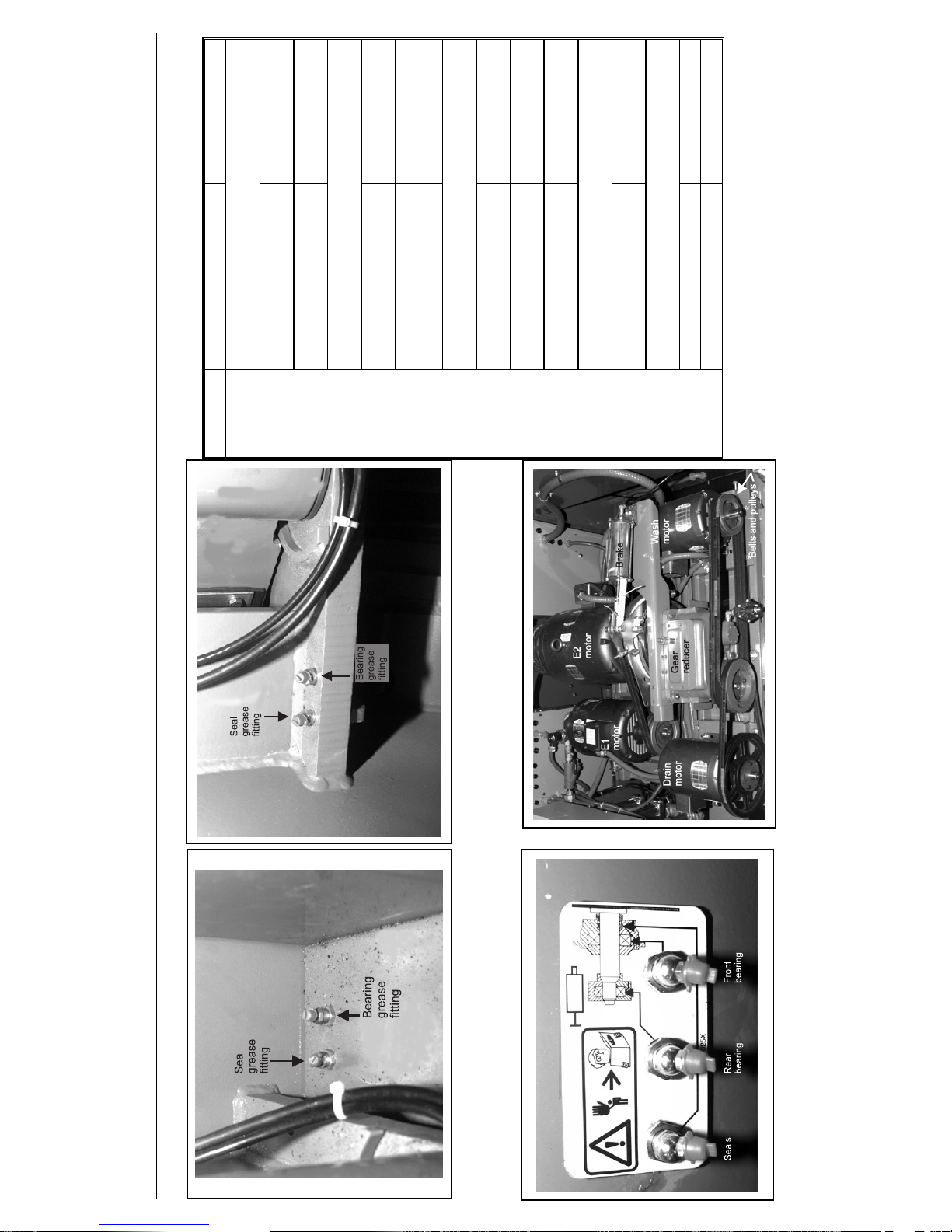
ÎFIGURE 9
(MSSM0201CE)
Î60044 and 72044 Staph-Guard
®
Front Bearing and Seal
Grease Fittings (located on front door)
ÎFIGURE 10
(MSSM0201CE)
Î60044 and 72044 Staph-Guard
®
Rear Bearing and Seal
Grease Fittings (located on rear door)
ÎFIGURE 11
(MSSM0201CE)
ÎAll Open-Pocket Machine Seal and Bearing
Grease Fitting Plate
ÎFIGURE 12
(MSSM0201CE)
ÎTypical Drive Train Components (48" machine shown)
ÏMonthly Maintenance Items
Frequency Component Action
Monthly
(see NOTE 4)
42" Open pocket main bearings and seals
FIGURE 11, NOTES 5 and 6
• Front and rear bearing grease fitting 0.12 ounces (3.54 grams),
two strokes at two locations
• Seal grease fitting 0.06 ounces (1.77 grams),
one stroke at one location
48" Open pocket main bearings and seals
FIGURE 11, NOTES 4, 5, and 6
• Front and rear bearing grease fitting 0.31 ounces (8.85 grams),
five strokes at two locations
• Seal grease fitting See “Semi-Annual
Maintenance Items” in this
section
52" and 72" Open pocket main bearings and seals
FIGURE 11, NOTES 4, 5, and 6
• Front bearing grease fitting 1.87 ounces (53.1 grams),
thirty strokes at one location
• Rear bearing grease fitting 0.62 ounces (17.7 grams),
ten strokes at one location
• Seal grease fitting 0.19 ounces (5.31 grams),
three strokes at one location
Hydro-cushions
®
FIGURES 2 and 3
• Upper and lower ball joints 0.12 ounces (3.54 grams),
two strokes at two locations
Drive train components
FIGURE 12
• Pulleys and clutches Check for wear
• All components Remove soil build-up
LUBRICATION AND PREVENTIVE MAINTENANCE
FOR HYDRO-CUSHION MACHINES MSSM0201CE/9840AV (5 of 11)
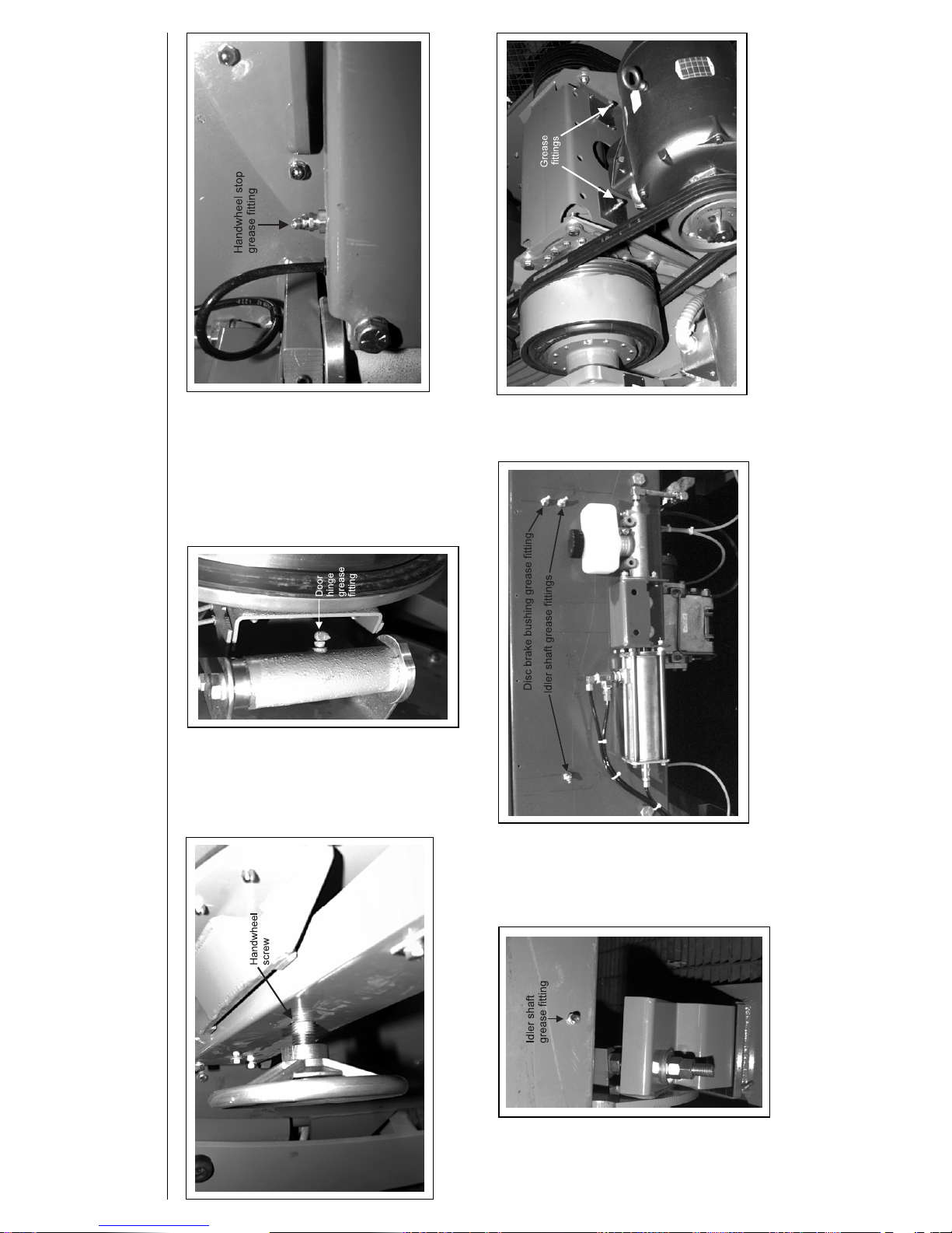
ÎFIGURE 13
(MSSM0201CE)
ÎHandwheel Screw
(42" Divided Cylinder and Staph-Guard
®
only)
ÎFIGURE 14
(MSSM0201CE)
ÎTypical Door Hinge
ÎFIGURE 15
(MSSM0201CE)
ÎHandwheel Stop
(42" Divided Cylinder and Staph-Guard
®
only)
ÎFIGURE 16
(MSSM0201CE)
Î42" Staph-Guard
®
ldler Shaft
Grease Fitting
ÎFIGURE 17
(MSSM0201CE)
Î60" and 72" Staph-Guard
®
Idler Shaft
and Disc Brake Grease Fittings
(60" shown)
ÎFIGURE 18
(MSSM0201CE)
ÎTypical Jackshaft
Grease Fittings
( 52" machine shown)
LUBRICATION AND PREVENTIVE MAINTENANCE
FOR HYDRO-CUSHION MACHINES MSSM0201CE/9840AV (6 of 11)
Ï Monthly Maintenance Items
Frequency Component Action
Monthly
(see NOTE 4)
Handwheel screw
(42" Divided Cylinder and
Staph-Guard
®
)
• Screw thread
FIGURE 13
Three drops of light machine
oil
Door hinges
• Grease fittings
FIGURE 14
0.12 ounces (3.54 grams),
two strokes at each location
Handwheel stop
(42" Divided Cylinder and
Staph-Guard
®
)
• Grease fitting
FIGURE 15
0.06 ounces (1.77 grams),
one stroke at one location
Idler shaft
(Staph-Guard
®
only)
• Grease fittings
FIGURES 16 and 17
0.31 ounces (8.85 grams),
five strokes at two locations
Disc brake
(60" and 72" Staph-Guard
®
only)
• Grease fittings
FIGURE 17
0.12 ounces (3.54 grams),
two strokes at one location
Jackshaft
(if equipped)
• Grease fittings
FIGURE 18
NOTES 5 and 6
0.12 ounces (3.54 grams)
two strokes at two locations
Water pressure regulator
(if equipped)
• Gauge
FIGURE 19
28 psi (0.14 kg/cm
2
)
Foundation
• Anchor bolts and grout Check condition
Tilt wheels
(42", 48", and 72" Tilt Models )
• Grease fittings
FIGURE 20
0.12 ounces (3.54 grams),
two strokes at each locations
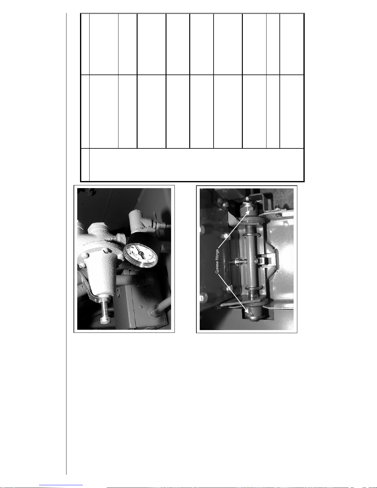
ÎFIGURE 19
(MSSM0201CE)
ÎWater Pressure Regulator and Gauge
(42" machine shown)
ÎFIGURE 20
(MSSM0201CE)
ÎTilt Wheels
(42"and 48" tilt machines only)
LUBRICATION AND PREVENTIVE MAINTENANCE
FOR HYDRO-CUSHION MACHINES MSSM0201CE/9840AV (7 of 11)
 Loading...