

Milnor 48040F7D, 48040F7J, 48040F7B, 48040F7Z Service Manual
Published Manual Number/ECN: MPI48F7ZAE/2018116A
• Publishing System: TPAS2
• Access date: 04/12/2018
• Document ECNs: Latest
Installation and Service
48040F7B, 48040F7D
48040F7J, 48040F7Z
PELLERIN MILNOR CORPORATION POST OFFICE BOX 400, KENNER, LOUISIANA 70063-0400, U.S.A.


Table of Contents
MPI48F7ZAE/18116A
Page Description Document
1 Limited Standard Warranty BMP720097/2008272A
2 How to Get the Necessary Repair Components BIUUUD19/20081231
3 Trademarks BNUUUU02/2017285A
5 1. Installation
6 Safety—Tilting Washer-Extractors BIUUUS27OT/20051111
12 Safety Supports: 48040F_ Air-tilt Washer-extractors BIIFLM18/20090331
14 Understanding Tag Guidelines BIUUUI02IF/20160711
18 How To Use the Safety Stands on 48" Air-tilting
Washer-extractors
19 Panels and Covers BMP150010/2015095A
21 Safety Placards and Locations ISO: 48040F7J, 48040F7W,
48040F7J(AZ), 48040F7Z (AZ)
23 Safety Placards and Locations ISO: 48040F7B, 48040F7N,
48040F7B (AZ), 48040F7D (AZ)
25 Foot Guard Assembly BMP150011/2015095A
26 48040F_, 48040H_, & 68036H_ Washer Extractor
Installation
31 Prevent Damage from Chemical Supplies and Chemical
Systems
36 About the Forces Transmitted by Milnor®
Washer-extractors
BIUUUS06F4/20060106
BIIFLM02/20150219
BIIFLM03/20150219
BIIFLI01AC/20140321
BIWUUI03/2017353A
BIWUUI02/20001108
39 2. Service and Maintenance
40 Service Connections BIIFUI01/20091215
43 Torque Requirements for Fasteners BIUUUM04/20180109
51 Disc Brake Maintenance BIEUUM01/2012266A
63 2.1. Drive Assemblies
64 Drive Components and Belt Installation BIIFLM32/20150219
67 Cylinder and Bearing Installation MWF100, 4840F BPWMEB01/2017466A
70 Bearing Assembly MWF100, 4840F BPWMEB02/2017466A
76 Air Injection Components BMP150013/2015095A
78 Brake Components BMP150014/2015095A
81 Air Cylinder Components and Installation BIIFLM11/2015176A
83 2.2. Suspension
84 Suspension Components BMP150015/2015095A
87 2.3. Tilt Assemblies
88 Air Tilt BMP150016/2015095A
91 2.4. Door Assemblies
92 Manual Door BMP150017/2015095A

Table of Contents, continued
MPI48F7ZAE/18116A
Page Description Document
97 Door Latch BIIFGM19/2010285A
99 2.5. Water, Steam & Drain
100 Water and Steam Schematics and Components BMP150018/2015095A
102 Water Inlet Components and Installation BMP150019/2015095A
105 Water Inlet Components for Tilt Washers BMP150020/2015095A
108 Steam Inlet Components and Installation BMP150021/2015095A
110 Drain Valve Body with One Valve BMP150022/2015095A
111 Drain Valve Body with Two Valves BMP150023/2015095A
113 2.6. Chemical Supply Assemblies
114 Soap Chute BMP150024/2015095A
116 Peristaltic Chemical inlets BMP150025/2015095A
119 2.7. Pneumatic Assemblies
120 Pneumatic Schematic 48040F7B, F7D, F7J, F7Z (AZ) BMP150026/2018116A
123 3. Reference
125 3.1. Dimensional Drawings
127 Dimensional Drawing - 4840F7J, 4840F7Z Non-Tilt Washer
Extractor
128 Dimensional Drawing - 4840F7J, 4840F7Z Options BD4840F7DB/2017145D
129 Dimensional Drawing - 4840F7B, 4840F7D Tilt Washer
Extractor
130 Dimensional Drawing - 4840F7B, 4840F7D Tilt Options BD4840FTDB/2014184D
131 Dimensional Drawing - Pedestal Base 4840F7J, F7W, F7B,
F7N
BD4840F7DE/2017145D
BD4840FTDE/2017145D
BD4840BSAE/2011354D

PELLERIN MILNOR CORPORATION
LIMITED STANDARD WARRANTY
We warrant to the original purchaser that MILNOR machines including electronic
hardware/software (hereafter referred to as “equipment”), will be free from defects in material and
workmanship for a period of one year from the date of shipment (unless the time period is specifically
extended for certain parts pursuant to a specific MILNOR published extended warranty) from our
factory with no operating hour limitation. This warranty is contingent upon the equipment being
installed, operated and serviced as specified in the operating manual supplied with the equipment,
and operated under normal conditions by competentoperators.
Providing we receive written notification of a warranted defect within 30 days of its discovery, we
will at our option repair or replace the defective part or parts, FOB our factory. We retain the right to
require inspection of the parts claimed defective in our factory prior to repairing or replacing same.
We will not be responsible, or in any way liable, for unauthorized repairs or service to our equipment,
and this warranty shall be void if the equipment is tampered with, modified, or abused, used for
purposes not intended in the design and construction of the machine, or is repaired or altered in any
way without MILNOR's written consent.
Parts damaged by exposure to weather, to aggressive water, or to chemical attack are not covered by
this warranty. For parts which require routine replacement due to normal wear such as gaskets,
contact points, brake and clutch linings, belts, hoses, and similar parts the warranty time period is 90
days.
We reserve the right to make changes in the design and/or construction of our equipment (including
purchased components) without obligation to change anyequipmentpreviouslysupplied.
ANY SALE OR FURNISHING OF ANY EQUIPMENT BY MILNOR IS MADE ONLY UPON
THE EXPRESS UNDERSTANDING THAT MILNOR MAKES NO EXPRESSED OR IMPLIED
WARRANTIES OF MERCHANTABILITY OR FITNESS FOR ANY PARTICULAR USE OR
PURPOSE
LIMITED TO REDHIBITION
DAMAGES ACTUALLY INCURRED OR REQUIRED AS A RESULT OF: THE FAILURE OF
ANY OTHER PERSON OR ENTITY TO PERFORM ITS RESPONSIBILITIES, FIRE OR
OTHER HAZARD, ACCIDENT, IMPROPER STORAGE, MIS-USE, NEGLECT, POWER OR
ENVIRONMENTAL CONTROL MALFUNCTIONS, DAMAGE FROM LIQUIDS, OR ANY
OTHER CAUSE BEYOND THE NORMAL RANGE OF USE. REGARDLESS OF HOW
CAUSED, IN NO EVENT SHALL MILNOR BE LIABLE FOR SPECIAL, INDIRECT,
PUNITIVE, LIQUIDATED, OR CONSEQUENTIAL COSTS OR DAMAGES, OR ANY COSTS
OR DAMAGES WHATSOEVER WHICH EXCEED THE PRICE PAID TO MILNOR FOR THE
EQUIPMENT ITSELLSORFURNISHES.
THE PROVISIONS ON THIS PAGE REPRESENT THE ONLY WARRANTY FROM MILNOR
AND NO OTHER WARRANTY OR CONDITIONS, STATUTORY OR OTHERWISE, SHALL
BE IMPLIED.
OR ANY OTHER WARRANTY IMPLIED BY LAW INCLUDING BUT NOT
. MILNOR WILL NOT BE RESPONSIBLE FOR ANY COSTS OR
WE NEITHER ASSUME, NOR AUTHORIZE ANY EMPLOYEE OR OTHER PERSON TO
ASSUME FOR US, ANY OTHER RESPONSIBILITY AND/OR LIABILITY IN CONNECTION
WITH THE SALE OR FURNISHING OF OUR EQUIPMENT TOANYBUYER.
BMP720097/2008272A
1

How to Get the Necessary Repair Components
BIUUUD19 (Published) Book specs- Dates: 20081231 / 20081231 / 20081231 Lang: ENG01 Applic: UUU
How to Get the Necessary Repair Components
This document uses Simplified Technical English.
Learn more at http://www.asd-ste100.org.
You can get components to repair your machine from the approved supplier where you got this
machine. Your supplier will usually have the necessary components in stock. You can also get
®
components from the Milnor
factory.
Tell the supplier the machine model and serial number and this data for each necessary component:
• The component number from this manual
• The component name if known
• The necessary quantity
• The necessary transportation requirements
• If the component is an electrical component, give the schematic number if known.
• If the component is a motor or an electrical control, give the nameplate data from the used
component.
To write to the Milnor factory:
Pellerin Milnor Corporation
Post Office Box 400
Kenner, LA 70063-0400
UNITED STATES
Telephone: 504-467-2787
Fax: 504-469-9777
Email: parts@milnor.com
— End of BIUUUD19 —
PELLERIN MILNOR CORPORATION
2

BNUUUU02 / 2017285A BNUUUU02 0000158094 A.3 7/13/17 1:53 PM Released
Trademarks
BNUUUU02.R01 0000158093 A.2 7/13/17 1:11 PM Released
These words are trademarks of Pellerin Milnor Corporation and other entities:
Table 1 Trademarks
AutoSpot™ GreenTurn™
CBW®
Drynet™
E-P Express®
GreenFlex™ MilMetrix® PurePulse®
Hydro-cushion™ MilTouch™ Ram Command™
Linear Costa Master™ MilTouch-EX™ RecircONE®
Milnor® PulseFlow®
E-P OneTouch® Linear Costo™ Miltrac™ RinSave®
E-P Plus®
Gear Guardian® Mildata®
Mentor®
MultiTrac™ SmoothCoil™
PBW™
End of document: BNUUUU02
Staph Guard®
Pellerin Milnor Corporation
3


Installation 1
5

Safety—Tilting Washer-Extractors
BIUUUS27 (Published) Book specs- Dates: 20051111 / 20051111 / 20060323 Lang: ENG01 Applic: EOT
Safety—Tilting Washer-Extractors
1. General Safety Requirements—Vital Information for
Management Personnel
Incorrect installation, neglected preventive maintenance, abuse, and/or improper repairs, or
changes to the machine can cause unsafe operation and personal injuries, such as multiple
fractures, amputations, or death. The owner or his selected representative (owner/user) is
responsible for understanding and ensuring the proper operation and maintenance of the machine.
The owner/user must familiarize himself with the contents of all machine instruction manuals.
The owner/user should direct any questions about these instructions to a Milnor® dealer or the
Milnor® Service department.
Most regulatory authorities (including OSHA in the USA and CE in Europe) hold the owner/user
ultimately responsible for maintaining a safe working environment. Therefore, the owner/user
must do or ensure the following:
• recognize all foreseeable safety hazards within his facility and take actions to protect his
personnel, equipment, and facility;
• work equipment is suitable, properly adapted, can be used without risks to health or safety,
and is adequately maintained;
• where specific hazards are likely to be involved, access to the equipment is restricted to those
employees given the task of using it;
• only specifically designated workers carry out repairs, modifications, maintenance, or
servicing;
• information, instruction, and training is provided;
• workers and/or their representatives are consulted.
[Document BIUUUS04]
Work equipment must comply with the requirements listed below. The owner/user must verify
that installation and maintenance of equipment is performed in such a way as to support these
requirements:
• control devices must be visible, identifiable, and marked; be located outside dangerous zones;
and not give rise to a hazard due to unintentional operation;
• control systems must be safe and breakdown/damage must not result in danger;
• work equipment is to be stabilized;
• protection against rupture or disintegration of work equipment;
• guarding, to prevent access to danger zones or to stop movements of dangerous parts before
the danger zones are reached. Guards to be robust; not give rise to any additional hazards; not
be easily removed or rendered inoperative; situated at a sufficient distance from the danger
zone; not restrict view of operating cycle; allow fitting, replacing, or maintenance by
restricting access to relevant area and without removal of guard/protection device;
• suitable lighting for working and maintenance areas;
• maintenance to be possible when work equipment is shut down. If not possible, then
protection measures to be carried out outside danger zones;
• work equipment must be appropriate for preventing the risk of fire or overheating; discharges
of gas, dust, liquid, vapor, other substances; explosion of the equipment or substances in it.
PELLERIN MILNOR CORPORATION
6

Safety—Tilting Washer-Extractors
y
y
r
r
1.1. Laundr
Facilit
—Provide a supporting floor that is strong and rigid enough to support–with
a reasonable safety factor and without undue or objectionable deflection–the weight of the fully
loaded machine and the forces transmitted by it during operation. Provide sufficient clearance fo
machine movement. Provide any safety guards, fences, restraints, devices, and verbal and/or
posted restrictions necessary to prevent personnel, machines, or other moving machinery from
accessing the machine or its path. Provide adequate ventilation to carry away heat and vapors.
Ensure service connections to installed machines meet local and national safety standards,
especially regarding the electrical disconnect (see the National Electric Code). Prominently post
safety information, including signs showing the source of electrical disconnect.
1.2. Personnel—Inform personnel about hazard avoidance and the importance of care and
common sense. Provide personnel with the safety and operating instructions that apply to them.
Verify that personnel use proper safety and operating procedures. Verify that personnel
understand and abide by the warnings on the machine and precautions in the instruction manuals.
1.3. Safety Devices—Ensure that no one eliminates or disables any safety device on the machine
or in the facility. Do not allow machine to be used with any missing guard, cover, panel or door.
Service any failing or malfunctioning device before operating the machine.
1.4. Hazard Information—Important information on hazards is provided on the machine safety
placards, in the Safety Guide, and throughout the other machine manuals. Placards must be kept
clean so that the information is not obscured. They must be replaced immediately if lost or
damaged. The Safety Guide and other machine manuals must be available at all times to
the appropriate personnel. See the machine service manual for safety placard part numbers.
Contact the Milnor Parts department for replacement placards or manuals.
1.5. Maintenance—Ensure the machine is inspected and serviced in accordance with the norms of
good practice and with the preventive maintenance schedule. Replace belts, pulleys, brake
shoes/disks, clutch plates/tires, rollers, seals, alignment guides, etc. before they are severely
worn. Immediately investigate any evidence of impending failure and make needed repairs (e.g.,
cylinder, shell, or frame cracks; drive components such as motors, gear boxes, bearings, etc.,
whining, grinding, smoking, or becoming abnormally hot; bending or cracking of cylinder, shell,
frame, etc.; leaking seals, hoses, valves, etc.) Do not permit service or maintenance by
unqualified personnel.
2. Safety Alert Messages—Internal Electrical and Mechanical
Hazards
[Document BIUUUS11]
The following are instructions about hazards inside the machine and in electrical enclosures.
WARNING 1 : Electrocution and Electrical Burn Hazards—Contact with electric powe
can kill or seriously injure you. Electric power is present inside the cabinetry unless the main
machine power disconnect is off.
• Do not unlock or open electric box doors.
• Do not remove guards, covers, or panels.
• Do not reach into the machine housing or frame.
• Keep yourself and others off of machine.
• Know the location of the main machine disconnect and use it in an emergency to remove
all electric power from the machine.
PELLERIN MILNOR CORPORATION
7
Safety—Tilting Washer-Extractors
r
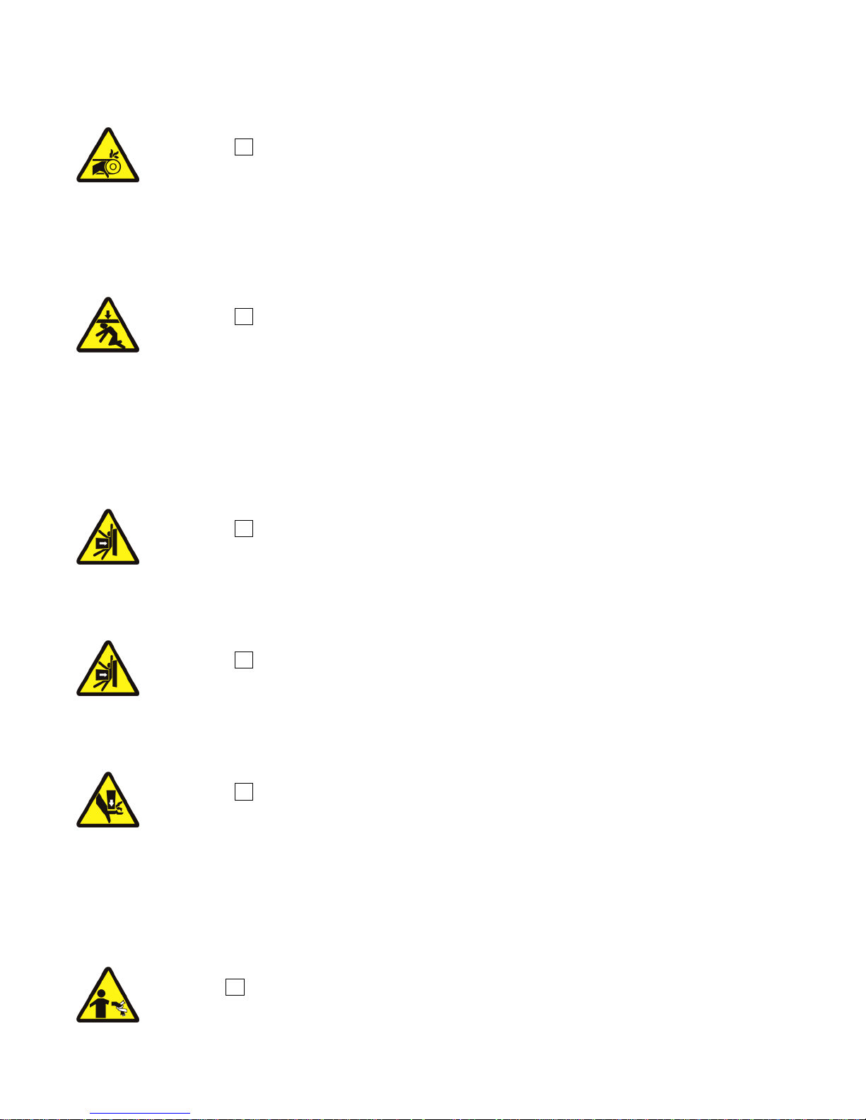
WARNING 2 : Entangle and Crush Hazards—Contact with moving components normally
isolated by guards, covers, and panels, can entangle and crush your limbs. These components
move automatically.
• Do not remove guards, covers, or panels.
• Do not reach into the machine housing or frame.
• Keep yourself and others off of machine.
• Know the location of all emergency stop switches, pull cords, and/or kick plates and use
them in an emergency to stop machine motion.
WARNING 3 : Crush Hazards—Tilting machines only—The machine housing will crush
your body or limbs if it descends or falls while you are under it. Housing can descend with powe
off or on. Manual operation of tilting valves overrides safety interlocks. Improper operation of
manual tilting valves may cause the housing to descend.
• Do not remove guards, covers, or panels.
• Do not reach into the machine housing or frame.
3. Safety Alert Messages—External Mechanical Hazards [Document
BIUUUS12]
The following are instructions about hazards around the front, sides, rear or top of the machine.
WARNING 4 : Strike and Crush Hazards—Machines with power operated door—The
moving door can strike you or crush or pinch your limbs if caught between the door and machine.
Some doors move automatically.
• Keep yourself and others clear of movement areas and paths.
• Keep both hands on the controls while operating.
• Do not operate the machine with malfunctioning two-hand manual controls.
WARNING 5 : Crush Hazards—Tilting machines only—The machine can crush your body
or limbs if you are caught between the tilting housing and a stationary object. Some machines tilt
automatically.
• Keep yourself and others clear of movement areas and paths.
• Keep both hands on the controls while operating.
• Do not operate the machine with malfunctioning two-hand manual controls.
WARNING 6 : Crush Hazards—Suspended machines only—Spaces between the shell and
housing can close and crush or pinch your limbs. The shell moves within the housing during
operation.
• Do not reach into the machine housing or frame.
• Keep yourself and others clear of movement areas and paths.
4. Safety Alert Messages—Cylinder and Processing Hazards
[Document BIUUUS13]
The following are instructions about hazards related to the cylinder and laundering process.
DANGER 7 : Entangle and Sever Hazards—Contact with goods being processed can
cause the goods to wrap around your body or limbs and dismember you. The goods are normally
isolated by the locked cylinder door.
PELLERIN MILNOR CORPORATION
8
Safety—Tilting Washer-Extractors
• Do not attempt to open the door or reach into the cylinder until the cylinder is stopped.
• Do not touch goods inside or hanging partially outside the turning cylinder.
• Do not operate the machine with a malfunctioning door interlock.
• Open pocket machines only—Do not jog the cylinder and pull the goods at the same time.
• Open pocket machines only—Keep yourself and others clear of cylinder and goods during
jogging operation.
• Do not operate the machine with malfunctioning two-hand manual controls.
• Know the location of all emergency stop switches, pull cords, and/or kick plates and use
them in an emergency to stop machine motion.
• Know the location of the main machine disconnect and use it in an emergency to remove
all electric power from the machine.
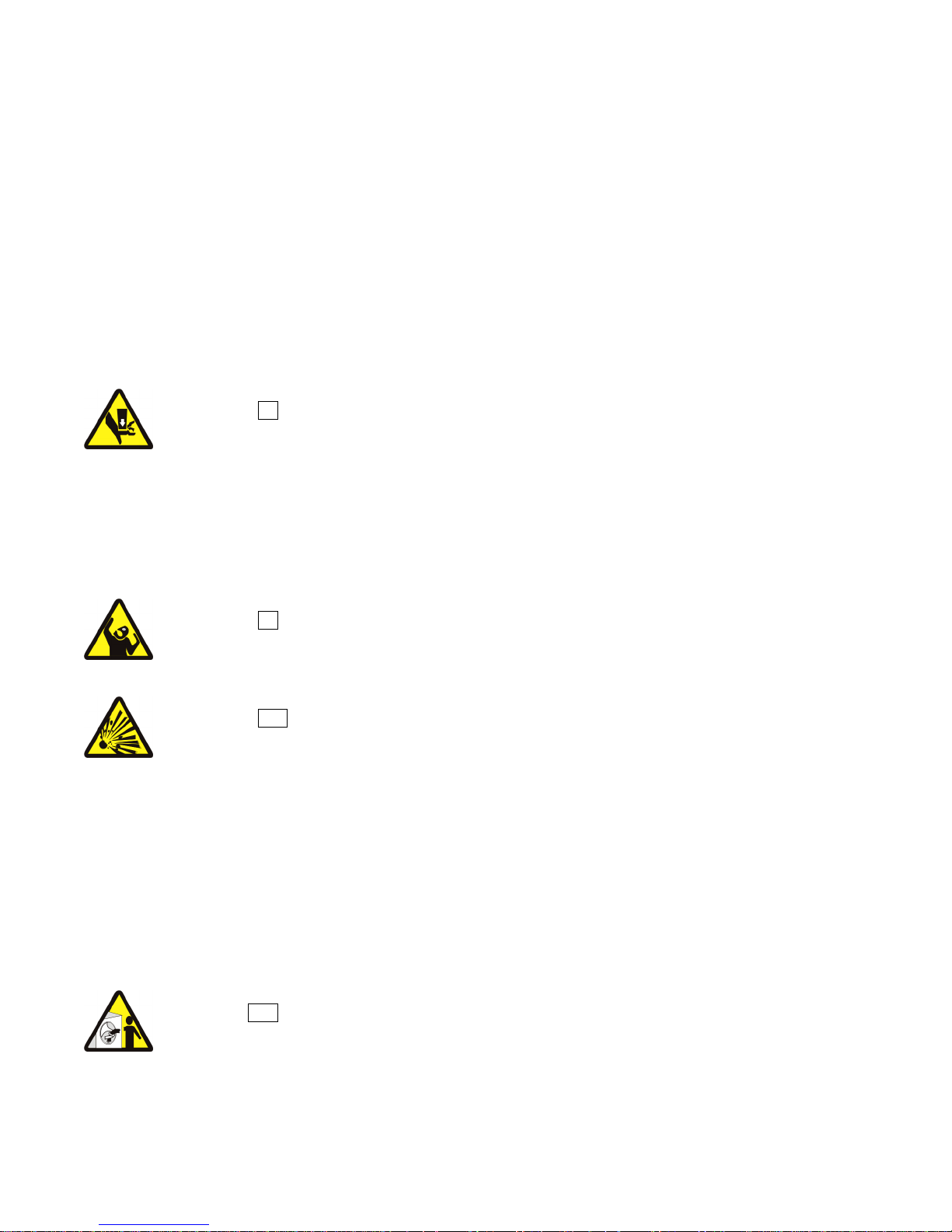
WARNING 8 : Crush Hazards—Contact with the turning cylinder can crush your limbs. The
cylinder will repel any object you try to stop it with, possibly causing the object to strike or stab
you. The turning cylinder is normally isolated by the locked cylinder door.
• Do not attempt to open the door or reach into the cylinder until the cylinder is stopped.
• Do not place any object in the turning cylinder.
• Do not operate the machine with a malfunctioning door interlock.
• Open pocket machines only—Keep yourself and others clear of cylinder and goods during
jogging operation.
• Do not operate the machine with malfunctioning two-hand manual controls.
WARNING 9 : Confined Space Hazards—Confinement in the cylinder can kill or injure
you. Hazards include but are not limited to panic, burns, poisoning, suffocation, heat prostration,
biological contamination, electrocution, and crushing.
• Do not attempt unauthorized servicing, repairs, or modification.
WARNING 10 : Explosion and Fire Hazards—Flammable substances can explode or
ignite in the cylinder, drain trough, or sewer. The machine is designed for washing with water,
not any other solvent. Processing can cause solvent-containing goods to give off flammable
vapors.
• Do not use flammable solvents in processing.
• Do not process goods containing flammable substances. Consult with your local fire
department/public safety office and all insurance providers.
5. Safety Alert Messages—Unsafe Conditions [Document BIUUUS14]
Damage and Malfunction Hazards
5.1.
5.1.1. Hazards Resulting from Inoperative Safety Devices
DANGER 11 : Entangle and Sever Hazards—Cylinder door interlock—Operating the
machine with a malfunctioning door interlock can permit opening the door when the cylinder is
turning and/or starting the cycle with the door open, exposing the turning cylinder.
• Do not operate the machine with any evidence of damage or malfunction.
PELLERIN MILNOR CORPORATION
9
Safety—Tilting Washer-Extractors
(
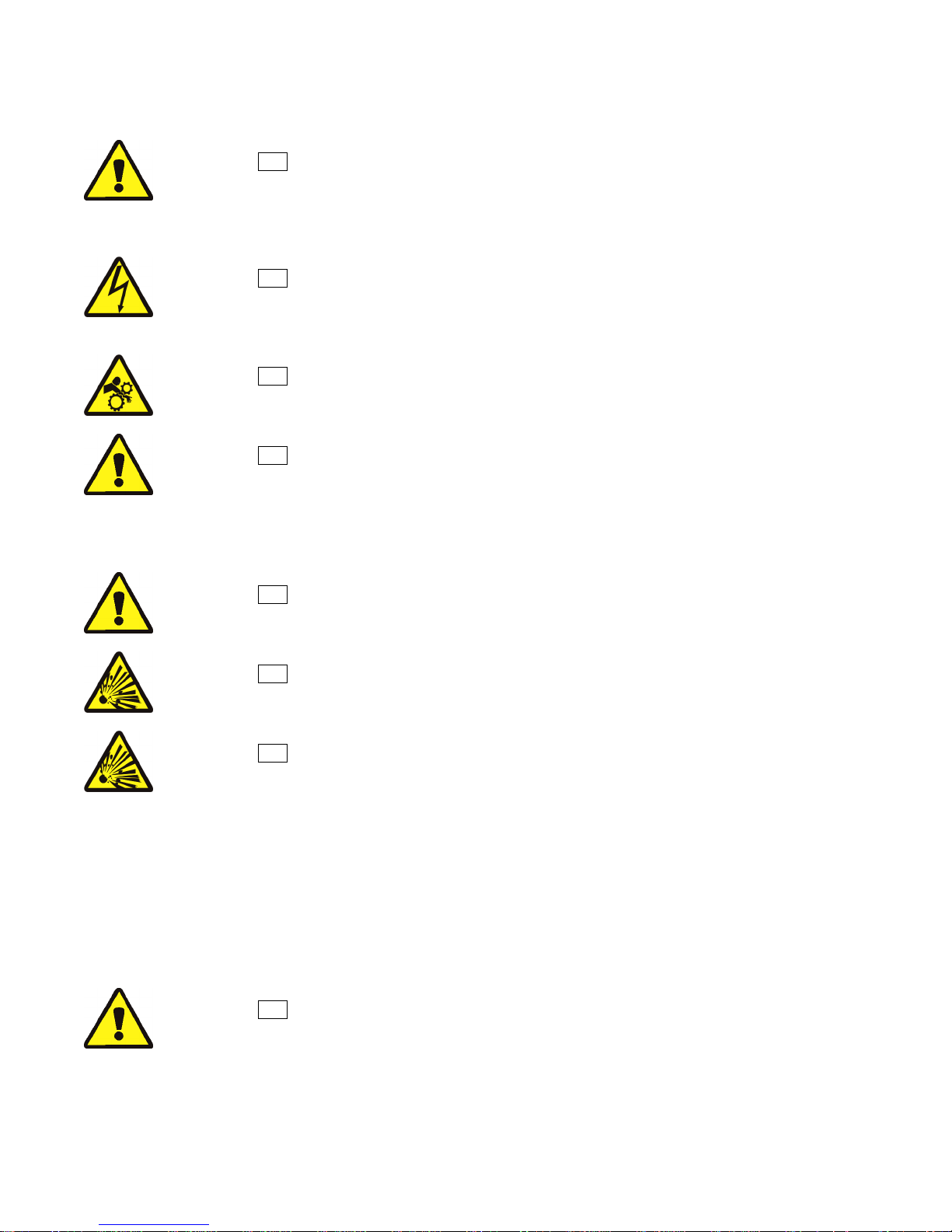
WARNING 12 : Multiple Hazards—Operating the machine with an inoperative safety device
can kill or injure personnel, damage or destroy the machine, damage property, and/or void the
warranty.
• Do not tamper with or disable any safety device or operate the machine with a
malfunctioning safety device. Request authorized service.
WARNING 13 : Electrocution and Electrical Burn Hazards—Electric box doors—
Operating the machine with any electric box door unlocked can expose high voltage conductors
inside the box.
• Do not unlock or open electric box doors.
WARNING 14 : Entangle and Crush Hazards—Guards, covers, and panels—Operating
the machine with any guard, cover, or panel removed exposes moving components.
• Do not remove guards, covers, or panels.
WARNING 15 : Crush Hazards—Down limit switches (machines with front and rear tilt
cylinders)—Failure of both front or both rear limit switches allows the seated tilt wheels on a
tilted machine to lift from their cradles. The housing will fall and lunge forward or rearward.
• Do not operate the machine with any evidence of damage or malfunction.
5.1.2. Hazards Resulting from Damaged Mechanical Devices
WARNING 16 : Multiple Hazards—Operating a damaged machine can kill or injure
personnel, further damage or destroy the machine, damage property, and/or void the warranty.
• Do not operate a damaged or malfunctioning machine. Request authorized service.
WARNING 17 : Explosion Hazards—Cylinder—A damaged cylinder can rip apart during
extraction, puncturing the shell and discharging metal fragments at high speed.
• Do not operate the machine with any evidence of damage or malfunction.
WARNING 18 : Explosion Hazards—Clutch and speed switch (multiple motor
machines)—A damaged clutch or speed switch can permit the low speed motor to engage during
extract. This will over-speed the motor and pulleys and can cause them to rip apart, discharging
metal fragments at high speed.
• Stop the machine immediately if any of these conditions occur: • abnormal whining sound
during extract • skidding sound as extract ends • clutches remain engaged or re-engage
during extract
5.2. Careless Use Hazards
5.2.1. Careless Operation Hazards—Vital Information for Operator Personnel
operator hazards throughout manual)
WARNING 19 : Multiple Hazards—Careless operator actions can kill or injure personnel,
damage or destroy the machine, damage property, and/or void the warranty.
• Do not tamper with or disable any safety device or operate the machine with a
malfunctioning safety device. Request authorized service.
• Do not operate a damaged or malfunctioning machine. Request authorized service.
• Do not attempt unauthorized servicing, repairs, or modification.
see also
PELLERIN MILNOR CORPORATION
10
Safety—Tilting Washer-Extractors
r
• Do not use the machine in any manner contrary to the factory instructions.
• Use the machine only for its customary and intended purpose.
• Understand the consequences of operating manually.
5.2.2. Careless Servicing Hazards—Vital Information for Service Personnel (see also
service hazards throughout manuals)
WARNING 20 : Electrocution and Electrical Burn Hazards—Contact with electric
power can kill or seriously injure you. Electric power is present inside the cabinetry unless the
main machine power disconnect is off.
• Do not service the machine unless qualified and authorized. You must clearly understand
the hazards and how to avoid them.
• Abide by the current OSHA lockout/tagout standard when lockout/tagout is called for in
the service instructions. Outside the USA, abide by the OSHA standard in the absence of
any other overriding standard.
WARNING 21 : Entangle and Crush Hazards—Contact with moving components
normally isolated by guards, covers, and panels, can entangle and crush your limbs. These
components move automatically.
• Do not service the machine unless qualified and authorized. You must clearly understand
the hazards and how to avoid them.
• Abide by the current OSHA lockout/tagout standard when lockout/tagout is called for in
the service instructions. Outside the USA, abide by the OSHA standard in the absence of
any other overriding standard.
WARNING 22 : Crush Hazards—Tilting machines only—The machine housing will crush
your body or limbs if it descends or falls while you are under it. Housing can descend with powe
off or on. Manual operation of tilting valves overrides safety interlocks. Improper operation of
manual tilting valves may cause the housing to descend.
• Secure both red safety supports in accordance with the instructions furnished, then lock
out and tag out power at the main machine disconnect before working under the tilted
machine.
• Do not operate the manual tilt valves with anyone under the machine.
• Do not operate the tilt controls with anyone under the machine.
WARNING 23 : Crush Hazards—Tilting machines with front and rear tilt cylinders—The
housing will fall and lunge forward or rearward if the tilt wheels on the non-tilted end lift out of
their cradles, even with safety supports in place.
• Understand the consequences of operating manually.
WARNING 24 : Confined Space Hazards—Confinement in the cylinder can kill or injure
you. Hazards include but are not limited to panic, burns, poisoning, suffocation, heat prostration,
biological contamination, electrocution, and crushing.
• Do not enter the cylinder until it has been thoroughly purged, flushed, drained, cooled,
and immobilized.
— End of BIUUUS27 —
PELLERIN MILNOR CORPORATION
11
BIIFLM18 (Published) Book specs- Dates: 20090331 / 20090917 / 20090917 Lang: ENG01 Applic: IFL
Safety Supports: 48040F_ Air-tilt Washer-extractors
This document uses Simplified Technical English.
Learn more at http://www.asd-ste100.org.
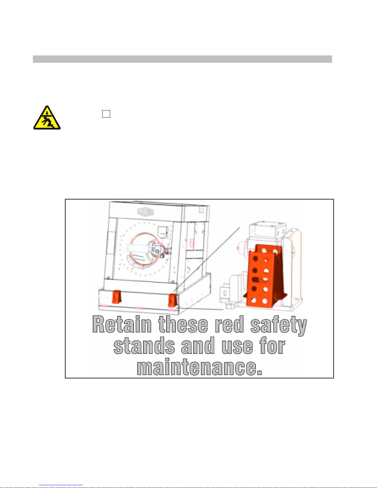
Milnor supplies safety supports with this machine.This document shows the safety supports,
identifies the safety support components, and tells how to install them.
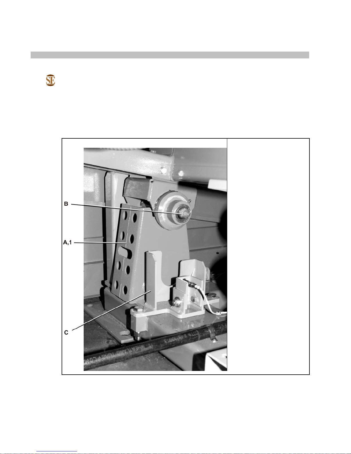
1. Safety Support Component Identification
Figure 1: Safety Supports: 48040F_ Air-tilt Washer-extractors
Detailed view Legend
A. Safety Stand. Used in two
front locations or two rear
locations.
B. Wheel. Used in four
locations.
C. Cradle. Used in four
locations.
.
PELLERIN MILNOR CORPORATION
12

Safety Supports: 48040F_ Air-tilt Washer-extractors
Table 1: Parts List—Safety Supports: 48040F_ Air-tilt Washer-extractors
Find the assembly for your machine and the letter shown in the "Item" column. The components for your
machine will show this letter or the word "all" in the "Used In" column. The numbers shown in the "Item"
column are those shown in the illustrations.
Used In Item Part Number Description/Nomenclature Comments
Assemblies
none
Components
all 1 W2 21822 Weldment, Safety stand, 4840F
2. How to Use the Safety Supports
Safety supports have a red color. You must keep and use safety supports for maintenance as
told in this document.
WARNING 2 : Crush Hazard—The mechanism can fall if there is a mechanical problem.
• Always install the safety supports and remove power from the machine before you do
maintenance in the machine.
• Do not hit the safety supports while you do maintenance.
• Replace damaged safety supports.
• Stow the safety supports properly.
Install the safety supports as follows:
1. Operate the Manual controls to lift the mechanism sufficiently to put the safety supports in
their positions.
2. Put each support in its position from the nearest side of the machine. Do not go across the
machine. Install the supports as shown in the figure. Use all supports.
3. Carefully operate the Manual controls to lower the mechanism until it touches the safety
supports. Immediately release the controls when the components touch.
4. Remove electrical power from the machine.
— End of BIIFLM18 —
PELLERIN MILNOR CORPORATION
13

Tag Guidelines for the Models Listed Below
This information may apply to models in addition to those listed above. It applies to
BIUUUI02IF (Published) Book specs- Dates: 20160711 / 20160711 / 20160711 Lang: ENG01 Applic: IFL
Tag Guidelines for the Models Listed Below
48040F7A 48040F7B 48040F7D 48040F7J 48040F7N 48040F7W 48040F7Z
Notice 1 :
paper tags. It does not apply to the vinyl or metal safety placards, which must remain
permanently affixed to the machine and replaced if no longer readable.
Paper tags on the machine provide installation guidelines and precautions. The tags can be tie-on
or adhesive. You can remove tie-on tags and white, adhesive tags after installation. Yellow
adhesive tags must remain on the machine.
14
PELLERIN MILNOR CORPORATION
Tag Guidelines for the Models Listed Below
This tag is usually wrapped around a motor housing. If the motor
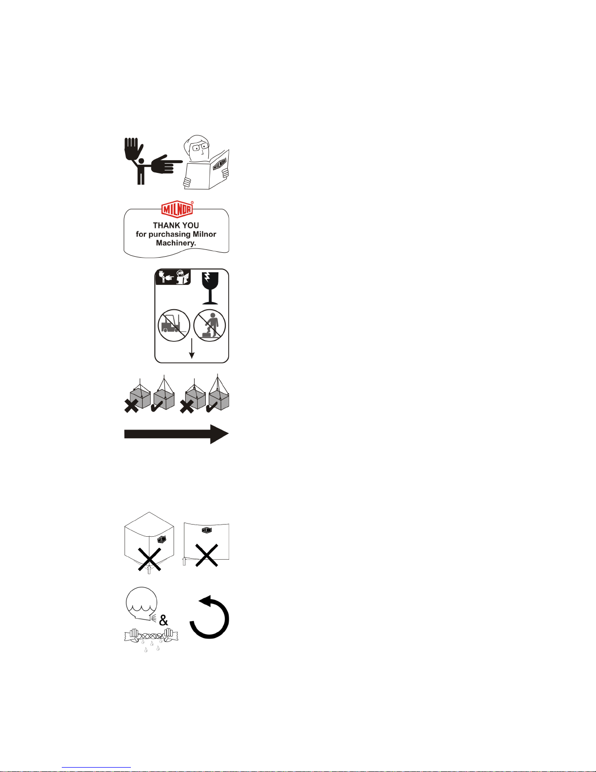
The following entries explain the installation tags. Each entry includes: 1) the tag illustration, 2)
the tag part number displayed st the bottom of the tag, and 3) the meaning of the tag.
Display or Action Explanation
Read the manuals before proceeding. This symbol appears on
most tags. The machine ships with safety, operator, and routine
maintenance guides for customer use. Milnor dealer manuals for
installing, servicing, and commissioning this machine are also
available from the Milnor Parts department.
B2TAG88005: This carefully built product was tested and
inspected to meet Milnor® performance and quality standards by
(identification mark of tester).
B2TAG94078: Do not forklift here; do not jack here; do not step
here—whichever applies.
B2TAG94079: Rig for crane lifting (either 3-point or 4-point,
depending on the number of lifting eyes provided) using a steep
angle on the chains (closer to vertical than horizontal).
B2TAG94081: Motor must rotate in this direction. On single
motor washer-extractors and centrifugal extractors, the drive
motor must turn in this direction during draining and extraction.
turns in the opposite direction when the machine is first tested,
the electrical hookup is incorrect and must be reversed as
explained in the schematic manual.
B2TAG94084: Do not lift from one corner of the machine, as
this can cause the frame to rack, damaging it.
B2TAG94097: The cylinder must rotate counterclockwise
during draining and extraction (spin) when viewed from here
(rear of machine). Otherwise, reverse the electric power
connections, as explained in the schematic manual.
PELLERIN MILNOR CORPORATION
15
may twist components, such as valves, damaging
Tag Guidelines for the Models Listed Below
Display or Action Explanation
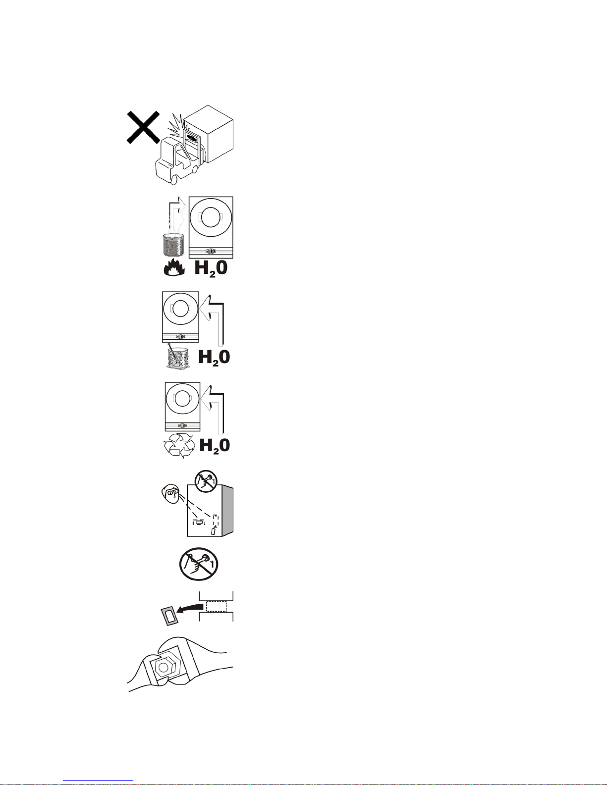
B2TAG94118: Do not strike shipping container during forklifting. Fragile components inside.
B2T2001013: Hot water connection.
B2T2001014: Cold water connection.
B2T2001015: Reuse (third) water connection.
B2T2001028: Look for tags inside the machine. These tags may
identify shipping restraints to be removed or components to be
installed. Do not start the machine until these actions are
completed.
B2T2002013: Do not start the machine until shipping restraints
are removed. This tag will appear on the outside of the machine
to alert you to the presence of internal shipping restraints. A tag
will also appear on the restraint to help identify it. Most, but not
all shipping restraints display the color red. Some shipping
restraints are also safety stands. Do not discard these.
B2T2003001: Hold the side of the connection stationary with a
wrench as you tighten the connection with another wrench.
Otherwise, you
them.
PELLERIN MILNOR CORPORATION
16

Tag Guidelines for the Models Listed Below
mount as shown. If this tag is present, the motor mount had to be
Display or Action Explanation
B2T2007015: Applies to 48040F7 models only. Adjust motor
lowered for shipment and must be raised before operating the
machine. The indicated dimension will result in the needed belt
tension.
— End of BIUUUI02 —
PELLERIN MILNOR CORPORATION
17
BIUUUS06 (Published) Book specs- Dates: 20060106 / 20060106 / 20060106 Lang: ENG01 Applic: 48040F7B 48040F7N
How To Use the Safety Stands on 48" Air-tilting Washerextractors
These machines are provided with two safety stands (painted red) for maintenance. After the
housing is tilted up, the stands are placed under the raised tilt wheels (front or rear). Use the
safety stands to perform maintenance on the machine while it is tilted.
WARNING 1 : Crush Hazard—The safety stands provide protection against the un-powered
descent of the housing during maintenance in the event of a leak in the pneumatic system. Such a
condition can cause the housing to fall quickly.
• Never work under the raised housing unless both safety stands are installed and power is
locked out/tagged out. Do not work near the raised housing with power on unless both
safety stands are installed.
• Install these safety components using the procedure prescribed in this document.
• Maintain these safety components in good condition.
• Designate a convenient, secure area to stow these safety components when not in use.
Figure 1: Safety Stands for 48" Air-tilting Washer-extractors
Install the safety stands as follows:
1. At the controls, tilt the machine as in normal operation. Tilt up only as far as needed to insert
the stands securely.
2. Referring to the figure, place the safety stands under the tilt wheels. Always use both stands.
3. At the controls, carefully lower the housing just until it is resting on the stands.
4. Lock out/tag out power to the machine.
— End of BIUUUS06 —
PELLERIN MILNOR CORPORATION
18
BMP150010/2015095A
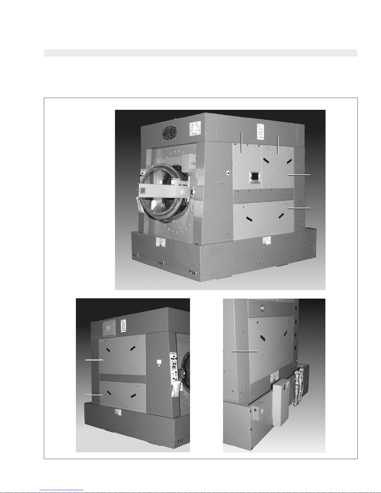
Panels & Covers
48040F7B, F7D, F7J, F7Z (AZ)
Page (1 / 2)
4
3
2
1
1
1
1
PELLERIN MILNOR CORPORATIONPELLERIN MILNOR CORPORATION
19
BMP150010/2015095A
Panels & Covers
48040F7B, F7D, F7J, F7Z (AZ)
6
5
Page (2 / 2)
7
5
Parts List—Panels & Covers
Find the correct assembly first, then find the needed components.The item letters (A, B, C, etc.) assigned to assemblies are referred to in the
"Used In" column to identify which components belong to an assembly. The item numbers (1, 2, 3, etc.) assigned to components relate the
parts list to theillustration.
Used In
-------------------------------------------------------------------COMPONENTS------------------------------------------------------------------
all 1 98CF22110 ASSY=LOWER SIDE DOOR, 4840F CSM
all 2 98CF22110B ASSY=UPPER SIDE DOOR, PNL-B, 4840F CSM
all 3 98CF22110C ASSY=UPPER SIDE DOOR, PNL-C, 4840F CSM
all 4 98CF22115A SIDE DOOR=PLASTIC SOAP CHUTE, 4840F CSM
all 5 98CF22124 ASSY=FRONT FOOT GUARD, 4840F CSM
all 6 98CX489258 RUBBER BUMPER, FOOT GUARD, 4840F CSM
all 7 98CX773680 BUMPER 2+1/2OD, CSM
Item
Part Number
Description
Comments
20
PELLERIN MILNOR CORPORATION
PELLERIN MILNOR CORPORATIONPELLERIN MILNOR CORPORATION
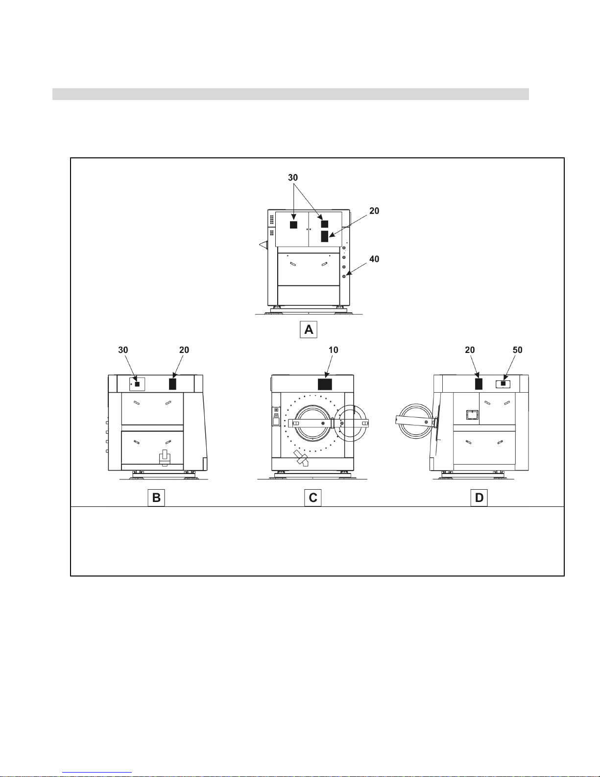
Figure 1: Safety Placards and Locations—ISO—48040F7J, 48040F7W, 48040F7J(AZ), 48040F7Z(AZ)
BIIFLM02 (Published) Book specs- Dates: 20150219 / 20150305 / 20150305 Lang: ENG01 Applic: IFL
Safety Placards and Locations—ISO—48040F7J, 48040F7W,
48040F7J (AZ), 48040F7Z (AZ)
General Views
A. Rear view
B. Left side view
C. Front view
D. Right side view
.
• This document is for placards that agree with: ISO
• If the placard is removed or you cannot read it, replace the placard immediately.
• If the placard is aluminum, the mounting holes are on the machine. Use #8 self-tapping
screws. If the placard is vinyl, put the placard in the approximate location shown.
Legend
21
PELLERIN MILNOR CORPORATION
Safety Placards and Locations—ISO—48040F7J, 48040F7W, 48040F7J (AZ), 48040F7Z (AZ)
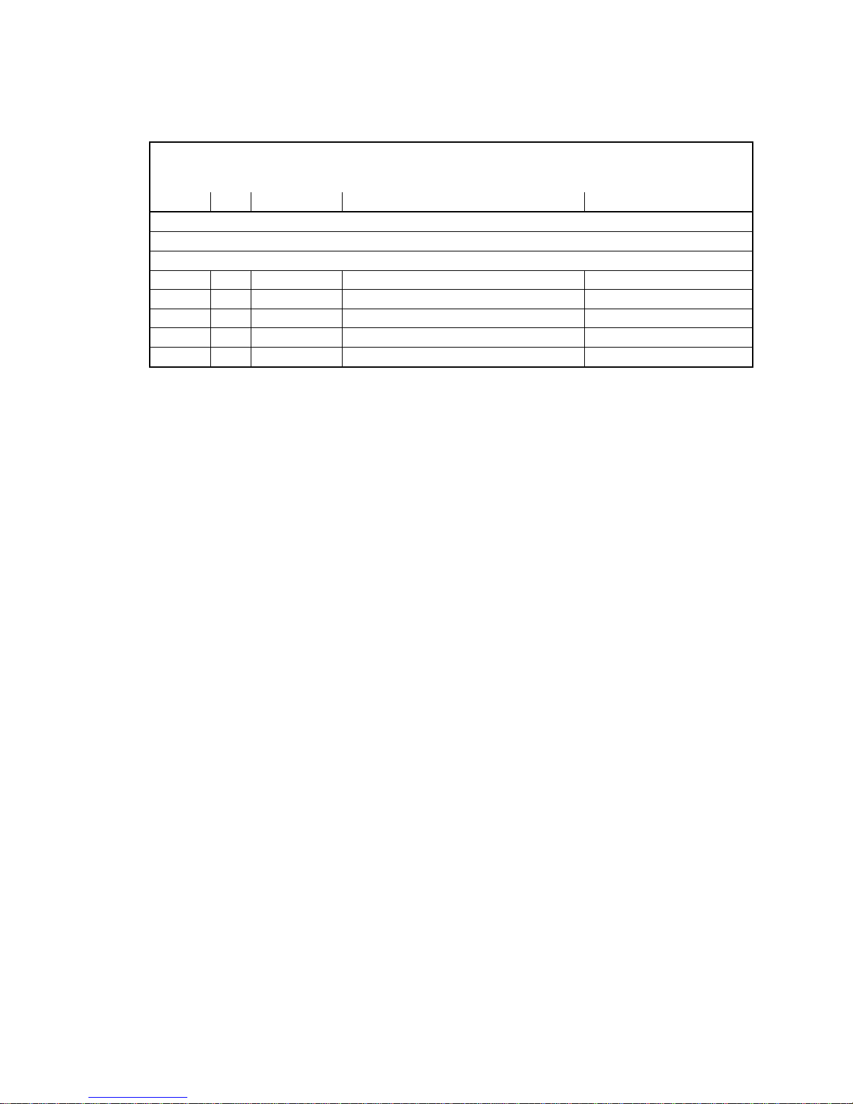
Table 1: Parts List—Safety Placards and Locations—ISO
Find the assembly for your machine and the letter shown in the "Item" column. The components for your
machine will show this letter or the word "all" in the "Used In" column. The numbers shown in the "Item"
column are those shown in the illustrations.
Used In
all
all
all
all
all
Item
10
20
30
40
50
Part Number
01 10631X
01 10628X
01 10377
01 10649X
01 10375
Dataplate, Hazard
Dataplate, Hazard
Dataplate, Hazard
Dataplate, Hazard
Dataplate, Hazard
Description/Nomenclature
Components
Assemblies
none
Comments
— End of BIIFLM02 —
PELLERIN MILNOR CORPORATION
22
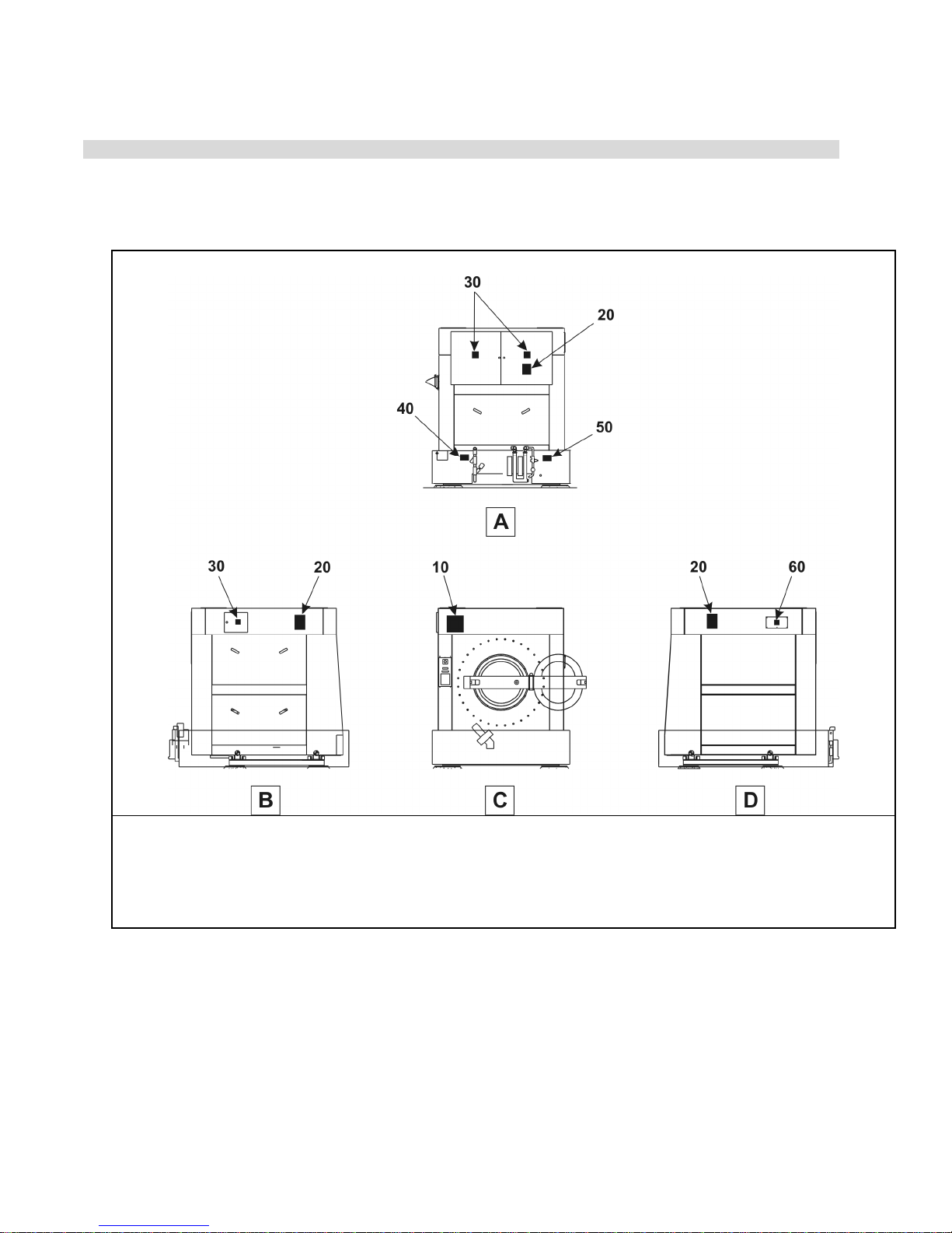
Figure 1: Safety Placards and Locations—ISO—48040F7B, 48040F7N, 48040F7B(AZ), 48040F7D(AZ)
BIIFLM03 (Published) Book specs- Dates: 20150219 / 20150305 / 20150305 Lang: ENG01 Applic: IFL
Safety Placards and Locations—ISO—48040F7B, 48040F7N,
48040F7B (AZ), 48040F7D (AZ)
General Views
A. Rear view
B. Left side view
C. Front view
D. Right side view
.
• This document is for placards that agree with:ISO
• If the placard is removed or you cannot read it, replace the placard immediately.
• If the placard is aluminum, the mounting holes are on the machine. Use #8 self-tapping
screws. If the placard is vinyl, put the placard in the approximate location shown.
Legend
23
PELLERIN MILNOR CORPORATION
Safety Placards and Locations—ISO—48040F7B, 48040F7N, 48040F7B (AZ), 48040F7D (AZ)
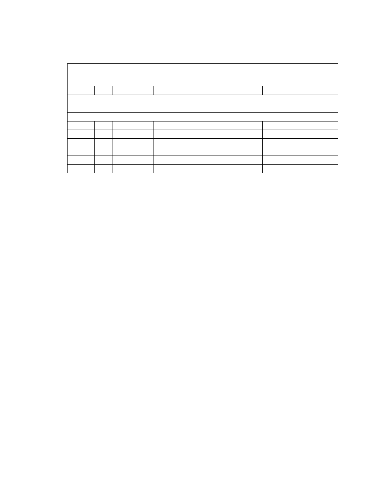
Table 1: Parts List—Safety Placards and Locations—ISO
Find the assembly for your machine and the letter shown in the "Item" column. The components for your
machine will show this letter or the word "all" in the "Used In" column. The numbers shown in the "Item"
column are those shown in the illustrations.
Used In
all
all
all
all
all
all
Item
10
20
30
40
50
60
Part Number
01 10629Y
01 10630X
01 10377
01 10649X
01 10648X
01 10375
Dataplate, Hazard
Dataplate, Hazard
Dataplate, Hazard
Dataplate, Hazard
Dataplate, Hazard
Dataplate, Hazard
Description/Nomenclature
Components
Assemblies
none
Comments
— End of BIIFLM03 —
PELLERIN MILNOR CORPORATION
24
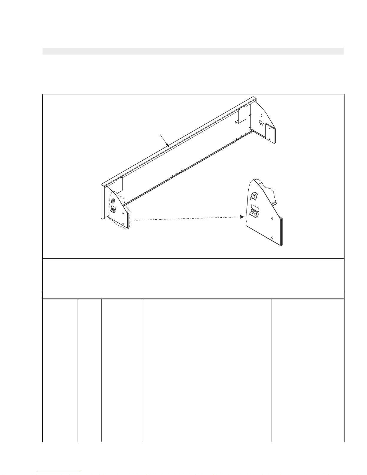
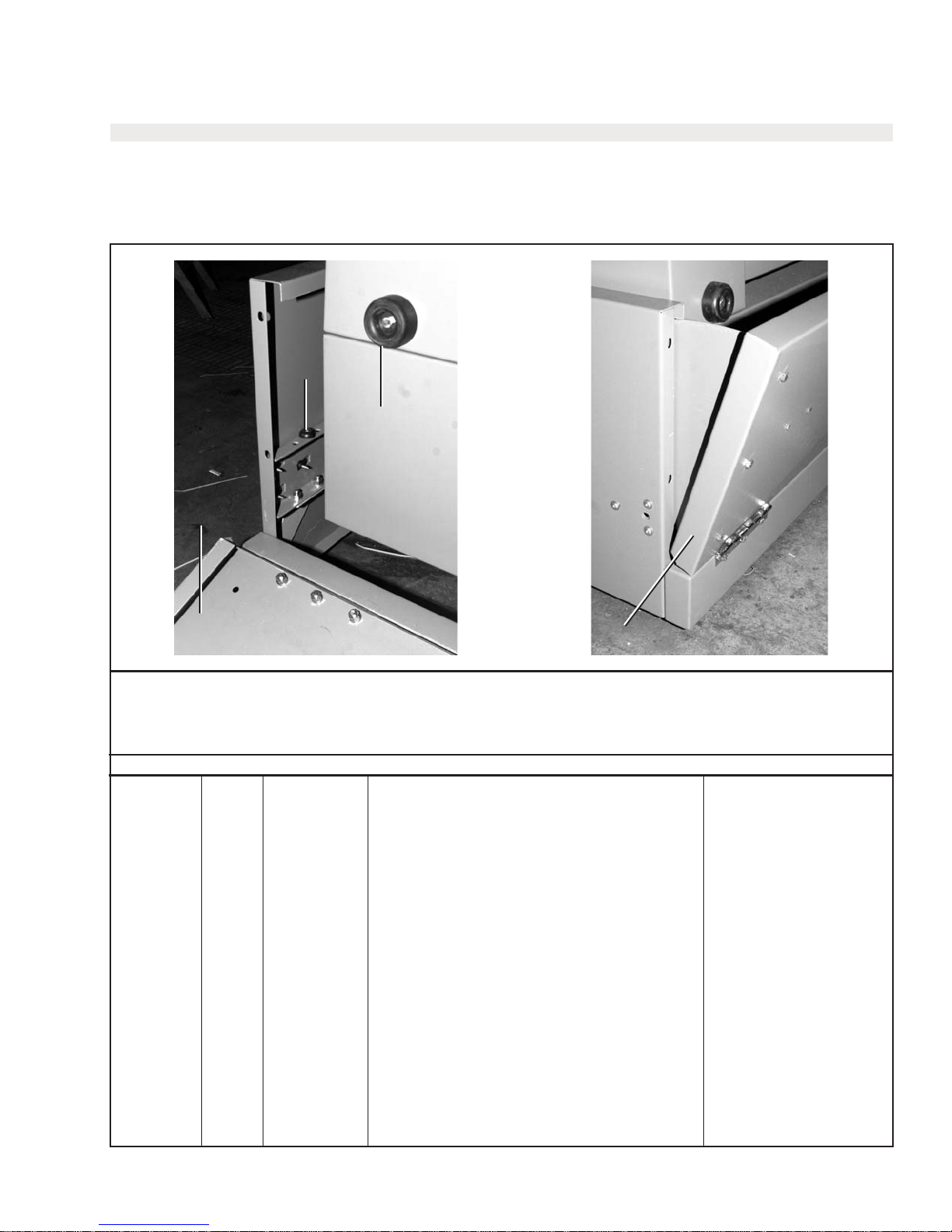
Foot Guard Assembly
48040F7B, F7D (AZ)
Page (1 / 1)BMP150011/2015095A
1
Find the correct assembly first, then find the needed components.The item letters (A, B, C, etc.) assigned to assemblies are referred to in the
Parts List—Foot Guard Assembly
"Used In" column to identify which components belong to an assembly. The item numbers (1, 2, 3, etc.) assigned to components relate the
parts list to theillustration.
Used In
-------------------------------------------------------------------------------------------COMPONENTS--------------------------------------------------------------------------
all 1 98CF22124 ASSY=FRONT FOOT GUARD, 4840F CSM
Item
Part Number
Description
Comments
PELLERIN MILNOR CORPORATION
25
BIIFLI01 (Published) Book specs- Dates: 20140321 / 20140321 / 20140321 Lang: ENG01 Applic: IFL IHU
48040F_, 48040H_ & 68036H_ Washer Extractor Installation
1. Handling
Note 1: Once the machine is given to the carrier for delivery, it is solely the responsibility of the carrier to
ensure that no damage occurs during transit. In addition to readily apparent damage, carriers are liable for
concealed damage. Do not hesitate to file a claim with the carrier if the machine is damaged in any way
during shipment. Milnor will be glad to assist you in filing your claim, but is not responsible for any
shipping damage to the machine once it has been delivered to the carrier in good condition.
1. Remove the protective coverings (leaving the machine on shipping skids) and examine
carefully for possible shipping damage. If the machine is damaged, notify the transportation
company immediately.
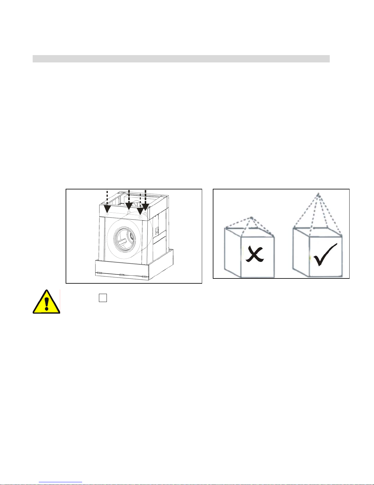
2. Locate the lift points as shown in Figure 1.
3. Attach chains as shown in Figure 2.
Figure 1: Where To Lift Figure 2: Rigger liable for damages
CAUTION 1 : Machine damage hazard—Improper placement of pickup chains can cause
direct or indirect damage to machine.
• Use a 4 point pickup (as shown in Figure 2)
• Use long pickup chains to prevent racking and/or twisting machine frame
2. Moving the Machine into Place
1. Use skids for fork lifting. If possible, leave the machine on shipping skids until it is near its
final position. Once skids are removed, carefully place forks under base. Do not allow the
forks to come in contact with valves, piping, motors, etc., located under the machine. Do not
push or hit the shell front when uncrating or installing the machine as it may cause the door to
leak.
2. Never push, pull, lift, jack, or exert pressure on any components that protrude from the
machine frame (shell front, door, electric boxes, controls, guards, conduits, conveyors,
piping, valves, drains, vents, tilt frames, etc.).
3. Do not pull on door conduit to help move the machine as the door switch may require
readjustment.
PELLERIN MILNOR CORPORATION
26
 Loading...