

Milnor 36021V5Z, 36026V5Z, 36021V7Z, 36026V7Z, 42030V6Z Service Manual
...
Published Manual Number/ECN: MAP36VXXEE/2019226A
• Publishing System: TPAS2
• Access date: 06/10/2019
• Document ECNs: Latest
Service
36021V5Z, 36026V5Z,
36021V7Z, 36026V7Z,
42026V6Z, 42030V6Z
Washer-Extractors
PELLERIN MILNOR CORPORATION POST OFFICE BOX 400, KENNER, LOUISIANA 70063-0400, U.S.A.


Table of Contents
MAP36VXXEE/19226A
Page Description Document
1 Limited Standard Warranty BMP720097/2019036
2 How to Get the Necessary Repair Components BIUUUD19/20081231
3 Trademarks BNUUUU02/2017285A
4 Safety—Rigid Washer Extractors BIUUUS27RU/20051111
9 Guards & Covers 36021V5Z, 36026V5Z BPWOCM02/2019177A
11 Guards & Covers 36021V7Z, 36026V7Z, 42026V6Z,
42030V6Z
13 About the Forces Transmitted by Milnor® Washer-extractors BIWUUI02/20001108
15 Installation Tag Guide Lines - 36021 & 36026V5Z, V7Z;
42026 & 42030V6Z
18 Prevent Damage from Chemical Supplies and Chemical
Systems
23 Safety Placard Use and Placement - 36021CPE, NSP, V5J,
V5Z & 36026V5J, V5Z
25 Safety Placard Use and Placement ISO - 36021CPE, NSP,
V5J, V5Z & 36026V5J, V5Z
27 Safety Placard Use and Placement 3621V7J, V7Z,
36026V7J,W, V7Z & 42026V6J,W, V7Z, 42030V6J,V6Z
29 Safety Placard Use and Placement ISO 36021V7J, V7Z,
36026V7J,W, V7Z, 42026V6J,W, V6Z, 42030V6J,V6Z
BPWOCM01/2019177A
BNWOAI01/2018212A
BIWUUI03/2017353A
BMP020109/2014356B
BMP020110/2014356B
BMP020111/2014385B
BMP020112/2014385B
31 1. Service and Maintenance
32 Torque Requirements for Fasteners BIUUUM04/20180109
41 2. Drive Assemblies
42 Drive Chart 36021V5J/V5Z, 36026V5J/V5Z BMP120027/2019177B
43 Drive Chart 36021V7J/V7Z, 36026V7J/V7Z BMP000010/2019177B
44 Drive Chart 42026V6J/V6Z, 42030V6J/V6Z BMP000011/2013352B
45 Motor Mount BMP000008/2013352B
49 3. Bearing Assemblies
50 Main Bearing, Shell, Cylinder Installation 36021V5Z,
36026V5Z with Starplate
BMP120028/2019177B
53 Bearing Assembly 36021V5Z, 36026V5Z with Starplate BMP120029/2019177B
55 Main Bearing, Shell, and Cylinder Installation 36021V7Z,
36026V7Z, 42026V6Z, 42030V6Z
BPWOCB02/2019177A
58 Bearing Assembly 36021V7Z, 36026V7Z, 42026V6Z,
42030V6Z
BPWOCB01/2019177A
61 4. 20 Inch Door Assemblies after 8/2016
62 20" Flat Front Door BMP160021/2017183A
65 Door Lock Mechanism BMP130002/2016434A

Table of Contents, continued
MAP36VXXEE/19226A
Page Description Document
68 Door Handle and Lock Actuator BIIFBM13/20140327
71 5. Chemical and Supply Devices
72 Soap Chute BPWOCC01/2019177A
73 Peristaltic Supply Assembly BMP190003/2019184A
76 5 Compartment Supply BPWOCC02/2019177A
79 6. Water Piping Assemblies
80 Schematic Symbols Key BMP920008/2000302V
81 Water Schematic BMP190004/2019177A
83 Water Inlet Assemblies BMP190002/2019177A
87 Steam Inlet BMP190005/2019177A
89 Drain Valve BMP190006/2019177A
91 3 Inch Electric Drain Valve BMP920017/2014155A
93 7. Control and Sensing Assemblies
94 Vibration Safety Switch Adjustments MSSMA408BE/199273BV
96 Vibration Safety Switch BMP910038/2012383B
97 Temperature Probe BMP180074/2018484A
98 Level Sensing BMP180079/2018484A

PELLERIN MILNOR CORPORATION
LIMITED STANDARD WARRANTY
We warrant to the original purchaser that MILNOR machines including electronic hardware/software
(hereafter referred to as “equipment”), will be free from defects in material and workmanship for a
period of one year from the date of shipment (unless the time period is specifically extended for
certain parts pursuant to a specific MILNOR published extended warranty) from our factory with no
operating hour limitation. This warranty is contingent upon the equipment being installed, operated
and serviced as specified in the operating manual supplied with the equipment, and operated under
normal conditions by competent operators.
Providing we receive written notification of a warranted defect within 30 days of its discovery, we
will—at our option—repair or replace the defective part or parts, EX Factory (labor and freight
specifically NOT included). We retain the right to require inspection of the parts claimed defective in
our factory prior to repairing or replacing same. We will not be responsible, or in any way liable, for
unauthorized repairs or service to our equipment, and this warranty shall be void if the equipment is
tampered with, modified, or abused, used for purposes not intended in the design and construction
of the machine, or is repaired or altered in any way without MILNOR's written consent.
Parts damaged by exposure to weather, to aggressive water, or to chemical attack are not covered
by this warranty. For parts which require routine replacement due to normal wear—such as gaskets,
contact points, brake and clutch linings, belts, hoses, and similar parts—the warranty time period is
90 days.
We reserve the right to make changes in the design and/or construction of our equipment (including
purchased components) without obligation to change any equipment previously supplied.
ANY SALE OR FURNISHING OF ANY EQUIPMENT BY MILNOR IS MADE ONLY UPON THE EXPRESS
UNDERSTANDING THAT MILNOR MAKES NO EXPRESSED OR IMPLIED WARRANTIES OF
MERCHANTABILITY OR FITNESS FOR ANY PARTICULAR USE OR PURPOSE OR ANY OTHER
WARRANTY IMPLIED BY LAW INCLUDING BUT NOT LIMITED TO REDHIBITION. MILNOR WILL NOT
BE RESPONSIBLE FOR ANY COSTS OR DAMAGES ACTUALLY INCURRED OR REQUIRED AS A RESULT
OF: THE FAILURE OF ANY OTHER PERSON OR ENTITY TO PERFORM ITS RESPONSIBILITIES, FIRE
OR OTHER HAZARD, ACCIDENT, IMPROPER STORAGE, MIS-USE, NEGLECT, POWER OR
ENVIRONMENTAL CONTROL MALFUNCTIONS, DAMAGE FROM LIQUIDS, OR ANY OTHER CAUSE
BEYOND THE NORMAL RANGE OF USE. REGARDLESS OF HOW CAUSED, IN NO EVENT SHALL
MILNOR BE LIABLE FOR SPECIAL, INDIRECT, PUNITIVE, LIQUIDATED, OR CONSEQUENTIAL COSTS
OR DAMAGES, OR ANY COSTS OR DAMAGES WHATSOEVER WHICH EXCEED THE PRICE PAID TO
MILNOR FOR THE EQUIPMENT IT SELLS OR FURNISHES.
THE PROVISIONS ON THIS PAGE REPRESENT THE ONLY WARRANTY FROM MILNOR AND NO OTHER
WARRANTY OR CONDITIONS, STATUTORY OR OTHERWISE, SHALL BE IMPLIED.
WE NEITHER ASSUME, NOR AUTHORIZE ANY EMPLOYEE OR OTHER PERSON TO ASSUME FOR US,
ANY OTHER RESPONSIBILITY AND/OR LIABILITY IN CONNECTION WITH THE SALE OR FURNISHING
OF OUR EQUIPMENT TO ANY BUYER.
BMP720097/19036
1

How to Get the Necessary Repair Components
BIUUUD19 (Published) Book specs- Dates: 20081231 / 20081231 / 20081231 Lang: ENG01 Applic: UUU
How to Get the Necessary Repair Components
This document uses Simplified Technical English.
Learn more at http://www.asd-ste100.org.
You can get components to repair your machine from the approved supplier where you got this
machine. Your supplier will usually have the necessary components in stock. You can also get
®
components from the Milnor
factory.
Tell the supplier the machine model and serial number and this data for each necessary component:
• The component number from this manual
• The component name if known
• The necessary quantity
• The necessary transportation requirements
• If the component is an electrical component, give the schematic number if known.
• If the component is a motor or an electrical control, give the nameplate data from the used
component.
To write to the Milnor factory:
Pellerin Milnor Corporation
Post Office Box 400
Kenner, LA 70063-0400
UNITED STATES
Telephone: 504-467-2787
Fax: 504-469-9777
Email: parts@milnor.com
— End of BIUUUD19 —
PELLERIN MILNOR CORPORATION
2

BNUUUU02 / 2017285A BNUUUU02 0000158094 A.3 7/13/17 1:53 PM Released
Trademarks
BNUUUU02.R01 0000158093 A.2 7/13/17 1:11 PM Released
These words are trademarks of Pellerin Milnor Corporation and other entities:
Table 1 Trademarks
AutoSpot™ GreenTurn™
CBW®
Drynet™
E-P Express®
GreenFlex™ MilMetrix® PurePulse®
Hydro-cushion™ MilTouch™ Ram Command™
Linear Costa Master™ MilTouch-EX™ RecircONE®
Milnor® PulseFlow®
E-P OneTouch® Linear Costo™ Miltrac™ RinSave®
E-P Plus®
Gear Guardian® Mildata®
Mentor®
MultiTrac™ SmoothCoil™
PBW™
End of document: BNUUUU02
Staph Guard®
Pellerin Milnor Corporation
3

Safety—Rigid Washer Extractors
BIUUUS27 (Published) Book specs- Dates: 20051111 / 20051111 / 20060322 Lang: ENG01 Applic: RUU
Safety—Rigid Washer Extractors
1. General Safety Requirements—Vital Information for
Management Personnel
Incorrect installation, neglected preventive maintenance, abuse, and/or improper repairs, or
changes to the machine can cause unsafe operation and personal injuries, such as multiple
fractures, amputations, or death. The owner or his selected representative (owner/user) is
responsible for understanding and ensuring the proper operation and maintenance of the machine.
The owner/user must familiarize himself with the contents of all machine instruction manuals.
The owner/user should direct any questions about these instructions to a Milnor® dealer or the
Milnor® Service department.
Most regulatory authorities (including OSHA in the USA and CE in Europe) hold the owner/user
ultimately responsible for maintaining a safe working environment. Therefore, the owner/user
must do or ensure the following:
• recognize all foreseeable safety hazards within his facility and take actions to protect his
personnel, equipment, and facility;
• work equipment is suitable, properly adapted, can be used without risks to health or safety,
and is adequately maintained;
• where specific hazards are likely to be involved, access to the equipment is restricted to those
employees given the task of using it;
• only specifically designated workers carry out repairs, modifications, maintenance, or
servicing;
• information, instruction, and training is provided;
• workers and/or their representatives are consulted.
[Document BIUUUS04]
Work equipment must comply with the requirements listed below. The owner/user must verify
that installation and maintenance of equipment is performed in such a way as to support these
requirements:
• control devices must be visible, identifiable, and marked; be located outside dangerous zones;
and not give rise to a hazard due to unintentional operation;
• control systems must be safe and breakdown/damage must not result in danger;
• work equipment is to be stabilized;
• protection against rupture or disintegration of work equipment;
• guarding, to prevent access to danger zones or to stop movements of dangerous parts before
the danger zones are reached. Guards to be robust; not give rise to any additional hazards; not
be easily removed or rendered inoperative; situated at a sufficient distance from the danger
zone; not restrict view of operating cycle; allow fitting, replacing, or maintenance by
restricting access to relevant area and without removal of guard/protection device;
• suitable lighting for working and maintenance areas;
• maintenance to be possible when work equipment is shut down. If not possible, then
protection measures to be carried out outside danger zones;
• work equipment must be appropriate for preventing the risk of fire or overheating; discharges
of gas, dust, liquid, vapor, other substances; explosion of the equipment or substances in it.
PELLERIN MILNOR CORPORATION
4

Safety—Rigid Washer Extractors
y
y
r
r
1.1. Laundr
Facilit
—Provide a supporting floor that is strong and rigid enough to support–with
a reasonable safety factor and without undue or objectionable deflection–the weight of the fully
loaded machine and the forces transmitted by it during operation. Provide sufficient clearance fo
machine movement. Provide any safety guards, fences, restraints, devices, and verbal and/or
posted restrictions necessary to prevent personnel, machines, or other moving machinery from
accessing the machine or its path. Provide adequate ventilation to carry away heat and vapors.
Ensure service connections to installed machines meet local and national safety standards,
especially regarding the electrical disconnect (see the National Electric Code). Prominently post
safety information, including signs showing the source of electrical disconnect.
1.2. Personnel—Inform personnel about hazard avoidance and the importance of care and
common sense. Provide personnel with the safety and operating instructions that apply to them.
Verify that personnel use proper safety and operating procedures. Verify that personnel
understand and abide by the warnings on the machine and precautions in the instruction manuals.
1.3. Safety Devices—Ensure that no one eliminates or disables any safety device on the machine
or in the facility. Do not allow machine to be used with any missing guard, cover, panel or door.
Service any failing or malfunctioning device before operating the machine.
1.4. Hazard Information—Important information on hazards is provided on the machine safety
placards, in the Safety Guide, and throughout the other machine manuals. Placards must be kept
clean so that the information is not obscured. They must be replaced immediately if lost or
damaged. The Safety Guide and other machine manuals must be available at all times to
the appropriate personnel. See the machine service manual for safety placard part numbers.
Contact the Milnor Parts department for replacement placards or manuals.
1.5. Maintenance—Ensure the machine is inspected and serviced in accordance with the norms of
good practice and with the preventive maintenance schedule. Replace belts, pulleys, brake
shoes/disks, clutch plates/tires, rollers, seals, alignment guides, etc. before they are severely
worn. Immediately investigate any evidence of impending failure and make needed repairs (e.g.,
cylinder, shell, or frame cracks; drive components such as motors, gear boxes, bearings, etc.,
whining, grinding, smoking, or becoming abnormally hot; bending or cracking of cylinder, shell,
frame, etc.; leaking seals, hoses, valves, etc.) Do not permit service or maintenance by
unqualified personnel.
2. Safety Alert Messages—Internal Electrical and Mechanical
Hazards
[Document BIUUUS11]
The following are instructions about hazards inside the machine and in electrical enclosures.
WARNING 1 : Electrocution and Electrical Burn Hazards—Contact with electric powe
can kill or seriously injure you. Electric power is present inside the cabinetry unless the main
machine power disconnect is off.
• Do not unlock or open electric box doors.
• Do not remove guards, covers, or panels.
• Do not reach into the machine housing or frame.
• Keep yourself and others off of machine.
• Know the location of the main machine disconnect and use it in an emergency to remove
all electric power from the machine.
PELLERIN MILNOR CORPORATION
5

Safety—Rigid Washer Extractors
WARNING 2 : Entangle and Crush Hazards—Contact with moving components normally
isolated by guards, covers, and panels, can entangle and crush your limbs. These components
move automatically.
• Do not remove guards, covers, or panels.
• Do not reach into the machine housing or frame.
• Keep yourself and others off of machine.
• Know the location of all emergency stop switches, pull cords, and/or kick plates and use
them in an emergency to stop machine motion.
3. Safety Alert Messages—Cylinder and Processing Hazards
[Document BIUUUS13]
The following are instructions about hazards related to the cylinder and laundering process.
DANGER 3 : Entangle and Sever Hazards—Contact with goods being processed can
cause the goods to wrap around your body or limbs and dismember you. The goods are normally
isolated by the locked cylinder door.
• Do not attempt to open the door or reach into the cylinder until the cylinder is stopped.
• Do not touch goods inside or hanging partially outside the turning cylinder.
• Do not operate the machine with a malfunctioning door interlock.
• Know the location of all emergency stop switches, pull cords, and/or kick plates and use
them in an emergency to stop machine motion.
• Know the location of the main machine disconnect and use it in an emergency to remove
all electric power from the machine.
WARNING 4 : Crush Hazards—Contact with the turning cylinder can crush your limbs. The
cylinder will repel any object you try to stop it with, possibly causing the object to strike or stab
you. The turning cylinder is normally isolated by the locked cylinder door.
• Do not attempt to open the door or reach into the cylinder until the cylinder is stopped.
• Do not place any object in the turning cylinder.
• Do not operate the machine with a malfunctioning door interlock.
WARNING 5 : Confined Space Hazards—Confinement in the cylinder can kill or injure
you. Hazards include but are not limited to panic, burns, poisoning, suffocation, heat prostration,
biological contamination, electrocution, and crushing.
• Do not attempt unauthorized servicing, repairs, or modification.
WARNING 6 : Explosion and Fire Hazards—Flammable substances can explode or ignite
in the cylinder, drain trough, or sewer. The machine is designed for washing with water, not any
other solvent. Processing can cause solvent-containing goods to give off flammable vapors.
• Do not use flammable solvents in processing.
• Do not process goods containing flammable substances. Consult with your local fire
department/public safety office and all insurance providers.
PELLERIN MILNOR CORPORATION
6
Safety—Rigid Washer Extractors
4. Safety Alert Messages—Unsafe Conditions [Document BIUUUS14]
Damage and Malfunction Hazards
4.1.
4.1.1. Hazards Resulting from Inoperative Safety Devices
DANGER 7 : Entangle and Sever Hazards—Cylinder door interlock—Operating the
machine with a malfunctioning door interlock can permit opening the door when the cylinder is
turning and/or starting the cycle with the door open, exposing the turning cylinder.
• Do not operate the machine with any evidence of damage or malfunction.
WARNING 8 : Multiple Hazards—Operating the machine with an inoperative safety device
can kill or injure personnel, damage or destroy the machine, damage property, and/or void the
warranty.
• Do not tamper with or disable any safety device or operate the machine with a
malfunctioning safety device. Request authorized service.
WARNING 9 : Electrocution and Electrical Burn Hazards—Electric box doors—
Operating the machine with any electric box door unlocked can expose high voltage conductors
inside the box.
• Do not unlock or open electric box doors.
WARNING 10 : Entangle and Crush Hazards—Guards, covers, and panels—Operating
the machine with any guard, cover, or panel removed exposes moving components.
• Do not remove guards, covers, or panels.
4.1.2. Hazards Resulting from Damaged Mechanical Devices
WARNING 11 : Multiple Hazards—Operating a damaged machine can kill or injure
personnel, further damage or destroy the machine, damage property, and/or void the warranty.
• Do not operate a damaged or malfunctioning machine. Request authorized service.
WARNING 12 : Explosion Hazards—Cylinder—A damaged cylinder can rip apart during
extraction, puncturing the shell and discharging metal fragments at high speed.
• Do not operate the machine with any evidence of damage or malfunction.
WARNING 13 : Explosion Hazards—Clutch and speed switch (multiple motor
machines)—A damaged clutch or speed switch can permit the low speed motor to engage during
extract. This will over-speed the motor and pulleys and can cause them to rip apart, discharging
metal fragments at high speed.
• Stop the machine immediately if any of these conditions occur: • abnormal whining sound
during extract • skidding sound as extract ends • clutches remain engaged or re-engage
during extract
PELLERIN MILNOR CORPORATION
7

4.2. Careless Use Hazards
(
Safety—Rigid Washer Extractors
4.2.1. Careless Operation Hazards—Vital Information for Operator Personnel
see also
operator hazards throughout manual)
WARNING 14 : Multiple Hazards—Careless operator actions can kill or injure personnel,
damage or destroy the machine, damage property, and/or void the warranty.
• Do not tamper with or disable any safety device or operate the machine with a
malfunctioning safety device. Request authorized service.
• Do not operate a damaged or malfunctioning machine. Request authorized service.
• Do not attempt unauthorized servicing, repairs, or modification.
• Do not use the machine in any manner contrary to the factory instructions.
• Use the machine only for its customary and intended purpose.
• Understand the consequences of operating manually.
4.2.2. Careless Servicing Hazards—Vital Information for Service Personnel (see also
service hazards throughout manuals)
WARNING 15 : Electrocution and Electrical Burn Hazards—Contact with electric
power can kill or seriously injure you. Electric power is present inside the cabinetry unless the
main machine power disconnect is off.
• Do not service the machine unless qualified and authorized. You must clearly understand
the hazards and how to avoid them.
• Abide by the current OSHA lockout/tagout standard when lockout/tagout is called for in
the service instructions. Outside the USA, abide by the OSHA standard in the absence of
any other overriding standard.
WARNING 16 : Entangle and Crush Hazards—Contact with moving components
normally isolated by guards, covers, and panels, can entangle and crush your limbs. These
components move automatically.
• Do not service the machine unless qualified and authorized. You must clearly understand
the hazards and how to avoid them.
• Abide by the current OSHA lockout/tagout standard when lockout/tagout is called for in
the service instructions. Outside the USA, abide by the OSHA standard in the absence of
any other overriding standard.
WARNING 17 : Confined Space Hazards—Confinement in the cylinder can kill or injure
you. Hazards include but are not limited to panic, burns, poisoning, suffocation, heat prostration,
biological contamination, electrocution, and crushing.
• Do not enter the cylinder until it has been thoroughly purged, flushed, drained, cooled,
and immobilized.
— End of BIUUUS27 —
PELLERIN MILNOR CORPORATION
8

BPWOCM02 / 2019177A
BPWOCM02 0000238963 A.2 5/20/19 2:42 PM Released
Guards & Covers
36021V5Z, 36026V5Z.
Figure 1.
1 of 2
BPWOCM02.R01 0000238962 A.2 5/20/19 2:41 PM Released
Pellerin Milnor Corporation
9
BPWOCM02 / 2019177A
BPWOCM02 0000238963 A.2 5/20/19 2:42 PM Released
Guards & Covers
36021V5Z, 36026V5Z.
Table 1. Parts List—
Find the assembly for your machine and the letter shown in the "Item" column. The components for your machine will show this
letter or the word "all" in the "Used In" column. The numbers shown in the "Item" column are those shown in the illustrations.
Used In Item Part Number
A GGS14811 INST=GUARD+COVER 36V5 LARGE DOOR
all 1 AGS14811 ASSY=FRONT COVER 36V5 LARGE DOOR
all 2 AGS14807A TOP COVER ASSY 36' STARPLATE
all 3 02 14815B COVER=SHELL ADJ BRKT
all 4 03 11082 BELTGRD-UPPER 3021/26 V5J
all 5 03 11083 BELTGRD-LOWER 3021/26 V5J
all 5 03 11083D BELTGUARD-LOWER DUAL
all 6 15P200 TRDCUT-F HXWASHD 3/8-16X3/4NIK
Description/Nomenclature
Assemblies
Components
Comments
2 of 2
10

BPWOCM01 / 2019177
BPWOCM01 0000233920 A.3 4/25/19 3:59 PM Released
Guards & Covers
36021V7Z, 36026V7Z, 42026V6Z, 42030V6Z
Figure 1. Front Covers
1 of 2
BPWOCM01.R01 0000233919 A.3 4/25/19 3:59 PM Released
Pellerin Milnor Corporation
11
BPWOCM01 / 2019177
BPWOCM01 0000233920 A.3 4/25/19 3:59 PM Released
Guards & Covers
36021V7Z, 36026V7Z, 42026V6Z, 42030V6Z
Figure 2. Rear Covers
2 of 2
Table 1. Parts List—Guards & Covers
Find the assembly for your machine and the letter shown in the "Item" column. The components for your machine will show this
letter or the word "all" in the "Used In" column. The numbers shown in the "Item" column are those shown in the illustrations.
Used In Item Part Number
A GGS14812 INST=GUARDS+COVERS 36V7 LARGE DOOR 36021V7Z,36026V7Z
B GGS119008 INST=GUARD+COVERS 42V LARGE DOOR 42026V6Z, 42030V6Z
A 1 AGS14812 ASSY=FRONT COVER ASSY 36V7 LARGE DOOR
B 1 AGS119008 FRONT COVER ASSY 42V LARGE DOOR
all 2 02 14815B COVER=SHELL ADJ BRKT
all 3 12P015B TRW BLK NYL PUSH FAST
all 4 03 11069 COVUPREAR CNTLBOX 36V7/42V6
all 5 03 11071 REAR COVER UP 36V7/42V6
A 6 03 11070 REAR COVER LOW 36V7/42V6
B 6 03 11070B REAR COVER LOW 4230V
A 7 03 11070A REARCOV LOW DUAL 36V/42V MK2
B 7
03 11070C REAR COVER LOW DUAL 4230V
Description/Nomenclature
Assemblies
Components
Comments
12

BIWUUI02 (Published) Book specs- Dates: 20001108 / 20001108 / 20100609 Lang: ENG01 Applic: WUU
About the Forces Transmitted by Milnor® Washer-extractors
During washing and extracting, all washer-extractors transmit both static and dynamic (cyclic)
forces to the floor, foundation, or any other supporting structure. During washing, the impact of
the goods as they drop imparts forces which are quite difficult to quantify. Size for size, both
rigid and flexibly-mounted machines transmit approximately the same forces during washing.
During extracting, rigid machines transmit forces up to 30 times greater than equivalent flexiblymounted models. The actual magnitude of these forces vary according to several factors:
• machine size,
• final extraction speed,
• amount, condition, and type of goods being processed,
• the liquor level and chemical conditions in the bath preceding extraction, and
• other miscellaneous factors.
®
Estimates of the maximum force normally encountered are available for each Milnor
model and
size upon request. Floor or foundation sizes shown on any Milnor® document are only for ongrade situations based only on previous experience without implying any warranty, obligation, or
responsibility on our part.
1.
Rigid Machines
Size for size, rigid washer-extractors naturally require a stronger, more rigid floor, foundation, or
other supporting structure than flexibly-mounted models. If the supporting soil under the slab is
itself strong and rigid enough and has not subsided to leave the floor slab suspended without
support, on grade installations can often be made directly to an existing floor slab if it has enough
strength and rigidity to safely withstand our published forces without transmitting undue
vibration. If the subsoil has subsided, or if the floor slab itself has insufficient strength and
rigidity, a deeper foundation, poured as to become monolithic with the floor slab, may be
required. Support pilings may even be required if the subsoil itself is “springy” (i.e., if its
resonant frequency is near the operating speed of the machine). Above-grade installations of rigid
machines also require a sufficiently strong and rigid floor or other supporting structure as
described below.
2.
Flexibly-mounted Machines
Size for size, flexibly-mounted machines generally do not require as strong a floor, foundation, or
other supporting structure as do rigid machines. However, a floor or other supporting structure
having sufficient strength and rigidity, as described in Section 3, is nonetheless vitally important
for these models as well.
3.
How Strong and Rigid?
Many building codes in the U.S.A. specify that laundry floors must have a minimum live load
capacity of 150 pounds per square foot (732 kilograms per square meter). However, even
compliance with this or any other standard does not necessarily guarantee sufficient rigidity. In
any event, it is the sole responsibility of the owner/user to assure that the floor and/or any other
supporting structure exceeds not only all applicable building codes, but also that the floor and/or
any other supporting structure for each washer-extractor or group of washer-extractors actually
has sufficient strength and rigidity, plus a reasonable factor of safety for both, to support the
weight of all the fully loaded machine(s) including the weight of the water and goods, and
including the published 360º rotating sinusoidal RMS forces that are transmitted by the
machine(s). Moreover, the floor, foundation, or other supporting structure must have sufficient
PELLERIN MILNOR CORPORATION
13
About the Forces Transmitted by Milnor® Washer-extractors
rigidity (i.e., a natural or resonant frequency many times greater than the machine speed with a
reasonable factor of safety); otherwise, the mentioned 360º rotating sinusoidal RMS forces can be
multiplied and magnified many times. It is especially important to consider all potential vibration
problems that might occur due to all possible combinations of forcing frequencies (rotating
speeds) of the machine(s) compared to the natural frequencies of the floor and/or any other
supporting structure(s). A qualified soil and/or structural engineer must be engaged for this
purpose.
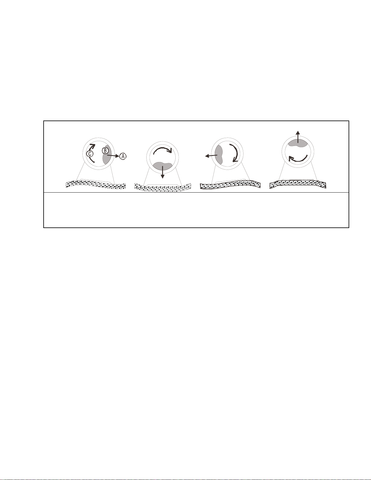
Figure 1: How Rotating Forces Act on the Foundation
Typical Machine
Legend
A. Direction of force
B. Load
C. Rotation (Frequency = RPM / 60)
.
Figure 1 above is intended to depict both on-grade and above-grade installations and is equally
applicable to flexibly-mounted washer-extractors, as well as to rigid models installed either
directly on a floor slab or on a foundation poured integrally with the slab. Current machine data is
®
available from Milnor
upon request. All data is subject to change without notice and may have
changed since last printed. It is the sole responsibility of every potential owner to obtain written
confirmation that any data furnished by Milnor® applies for the model(s) and serial number(s) of
the specific machines.
— End of BIWUUI02 —
PELLERIN MILNOR CORPORATION
14
IBNWOAI01 / 2018212
BNWOAI01 0000170412 A.2 5/21/18 3:17 PM Released
Installation Tag Guidelines
BNWOAI01.R01 0000187126 A.2 5/21/18 3:17 PM Released
36021V5Z 36021V7Z 36026V5Z 36026V7Z
42026V6Z 42030V6Z
NOTICE: This information may apply to models in addition to those listed above. It
applies to paper tags. It does not apply to the vinyl or metal safety placards, which must
remain permanently affixed to the machine and replaced if no longer readable.
Paper tags on the machine provide installation guidelines and precautions. The tags can be tie-on
or adhesive. You can remove tie-on tags and white, adhesive tags after installation. Yellow adhesive tags must remain on the machine.
The following entries explain the installation tags. Each entry includes: 1) the tag illustration, 2)
the tag part number at the bottom of the tag, and 3) the meaning of the tag.
Display or Action Explanation
Read the manuals before proceeding. This symbol appears on
most tags. The machine ships with safety, operator, and routine
maintenance guides for customer use. Milnor dealer manuals for
installing, commissioning, and servicing the machine are also
available from the Milnor Parts department.
B2TAG88005: This carefully built product was tested and inspected to meet Milnor performance and quality standards by
(identification mark of tester).
B2TAG93013: This bearing housing was lubricated at the Milnor
factory before shipment. (Only used on 36” V models. Not used
on 42” V models.)
B2TAG94078: Do not forklift here; do not jack here; do not step
here—whichever applies.
B2TAG94081: Motor must rotate in this direction. On single motor washer-extractors and centrifugal extractors, the drive motor
must turn in this direction during draining and extraction. This tag
is usually wrapped around a motor housing. If the motor turns in
the opposite direction when the machine is first tested, the electrical hookup is incorrect and must be reversed as explained in the
schematic manual.
Pellerin Milnor Corporation
15
Installation Tag Guidelines
B2TAG94097: The cylinder must rotate counterclockwise during
draining and extraction (spin) when viewed from here (rear of machine). Otherwise, reverse the electric power connections, as explained in the schematic manual.
B2TAG94099: Do not strike the shell door when fork-lifting. This
can cause the door to leak.
B2T2001013: Hot water connection.
B2T2001014: Cold water connection.
B2T2001015: Reuse (third) water connection. (Optional)
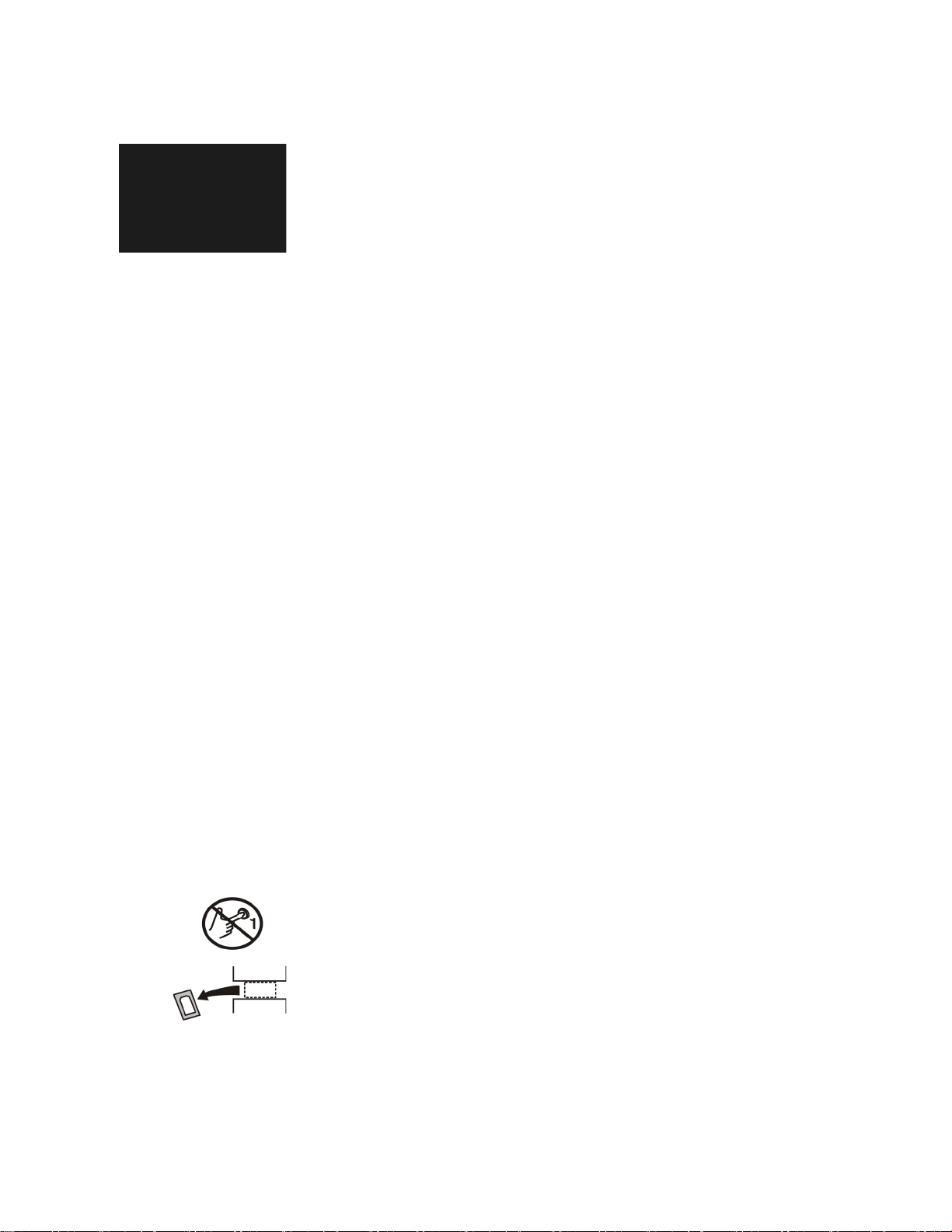
B2T2001028: Look for tags inside the machine. These tags may
identify shipping restraints to be removed or components to be installed. Do not start the machine until these actions are completed.
B2T2002013: Do not start the machine until shipping restraints
are removed. This tag will appear on the outside of the machine to
alert you to the presence of internal shipping restraints. A tag will
also appear on the restraint to help identify it. Most, but not all
shipping restraints display the color red. Some shipping restraints
are also safety stands. Do not discard these.
16
Pellerin Milnor Corporation

Installation Tag Guidelines
B2T2003001: Hold the side of the connection stationary with a
wrench as you tighten the connection with another wrench. Otherwise, you may twist components, such as valves, damaging them.
B2T2004027: Steam connection. (Optional)
End of document: BNWOAI01
Pellerin Milnor Corporation
17

BIWUUI03 / 2017353A BNUUUR02 0000160550 A.2 8/29/17 3:22 PM Released
Prevent Damage from Chemical Supplies and Chemical Systems
BNUUUR02.C01 0000160549 A.2 8/29/17 3:22 PM Released
All Milnor®washer-extractors and CBW®tunnel washers use stainless steel with the AISI 304
specification. This material gives good performance when chemical supplies are correctly applied. If chemical supplies are incorrectly applied, this material can be damaged. The damage can
be very bad and it can occur quickly.
Chemical supply companies usually:
• supply chemical pump systems that put the supplies in the machine,
• connect the chemical pump system to the machine,
• write wash formulas that control the chemical concentrations.
The company that does these procedures must make sure that these procedures do not cause damage. Pellerin Milnor Corporation accepts no responsibility for chemical damage to the ma-
chines it makes or to the goods in a machine.
1. How Chemical Supplies Can Cause Damage
Dangerous Chemical Supplies and Wash Formulas
Some examples that can cause damage are:
• a very high concentration of chlorine bleach,
BNUUUR02.R01 0000160548 A.2 A.4 8/30/17 3:15 PM Released
• a mixture of acid sour and hypo chlorite,
• chemical supplies (examples: chlorine bleach, hydrofluosilicic acid) that stay on the stainless
steel because they are not quickly flushed with water.
The book “Textile Laundering Technology” by Charles L. Riggs gives data about correct chemical supplies and formulas.
Incorrect Configuration or Connection of Equipment
Many chemical systems:
• do not prevent a vacuum in the chemical tube (for example, with a vacuum breaker) when the
pump is off,
• do not prevent flow (for example, with a valve) where the chemical tube goes in the machine.
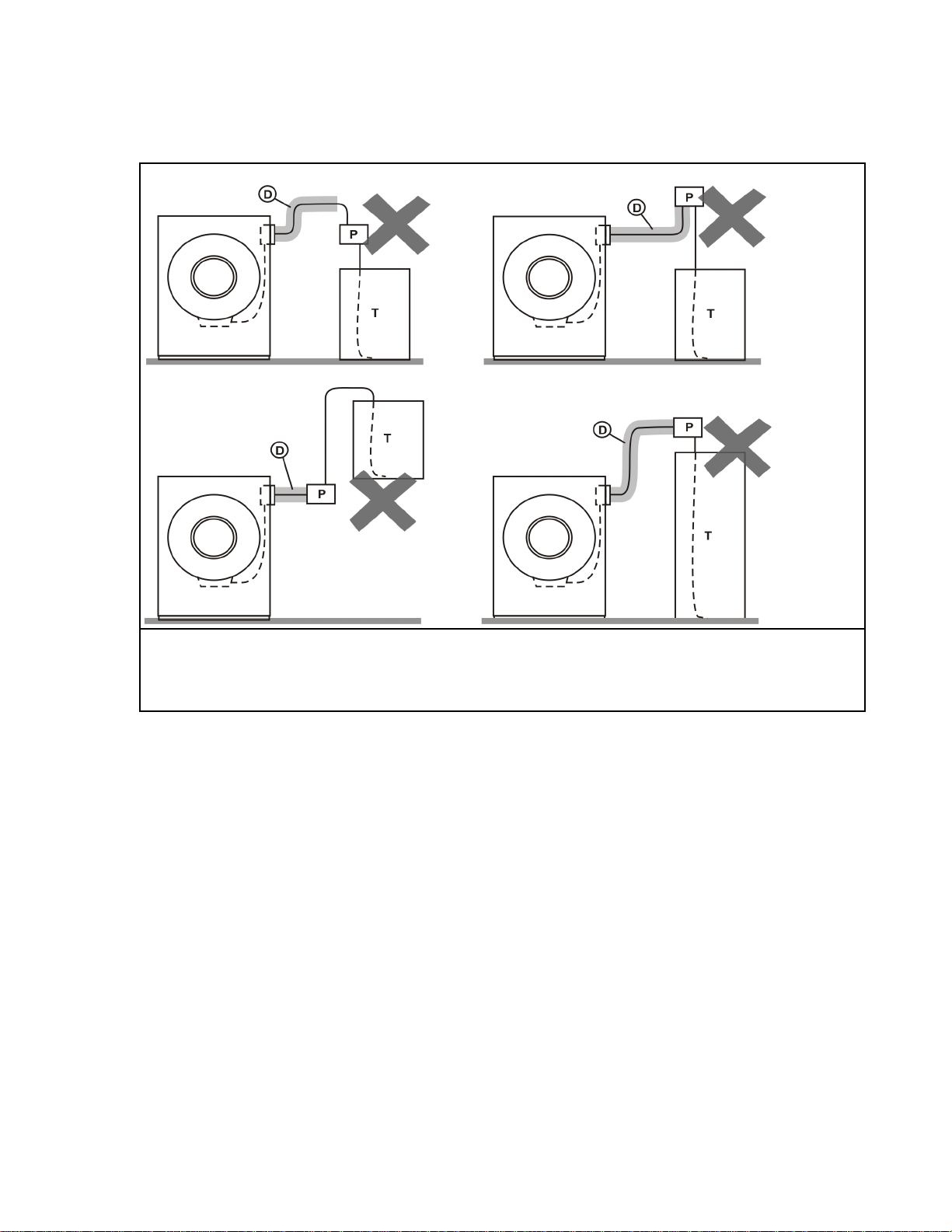
Damage will occur if a chemical supply can go in the machine when the chemical system is off.
Some configurations of components can let the chemical supplies go in the machine by a siphon
(Figure 1. Incorrect Configurations That Let the Chemical Supply Go In the Machine by a Si-
phon). Some can let chemical supplies go in the machine by gravity (Figure 2. Incorrect Configurations That Let the Chemical Supply Go In the Machine by Gravity).
Pellerin Milnor Corporation
18
Prevent Damage from Chemical Supplies and Chemical Systems
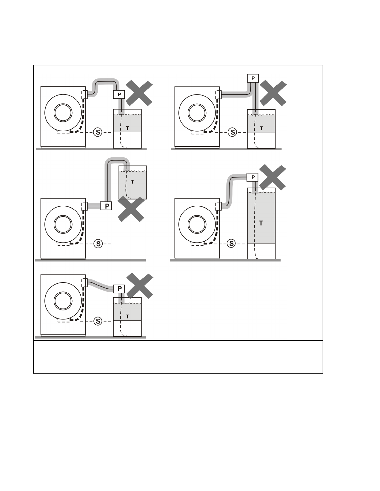
Figure 1. Incorrect Configurations That Let the Chemical Supply Go In the Machine by a Siphon
Schematic Views
Legend
P. Pump
T. Chemical tank
S. The siphon occurs above here. Liquid in the gray parts of the chemical tube and tank can go in the machine.
Pellerin Milnor Corporation
19
Prevent Damage from Chemical Supplies and Chemical Systems
Figure 2. Incorrect Configurations That Let the Chemical Supply Go In the Machine by Gravity
Schematic Views
Legend
P. Pump
T. Chemical tank
D. Chemical tube. Liquid in the gray areas can go in the machine.
2. Equipment and Procedures That Can Prevent Damage
BNUUUR02.R02 0000160545 A.2 A.8 8/30/17 3:28 PM Released
Use the chemical manifold supplied.
There is a manifold on the machine to attach chemical tubes from a chemical pump system. The
manifold has a source of water to flush the chemical supplies with water.
Pellerin Milnor Corporation
20
Prevent Damage from Chemical Supplies and Chemical Systems
Figure 3. Examples of Manifolds for Chemical Tubes. Your equipment can look different.
Close the line.
If the pump does not always close the line when it is off, use a shutoff valve to do this.
Do not let a vacuum occur.
Supply a vacuum breaker in the chemical line that is higher than the full level of the tank.
Flush the chemical tube with water.
If the liquid that stays in the tube between the pump and the machine can flow in the machine,
flush the tube with water after the pump stops.
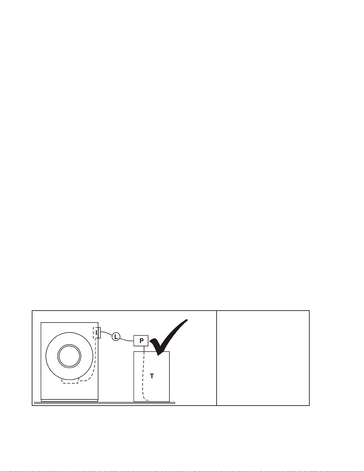
Put the chemical tube fully below the inlet.
It is also necessary that there is no pressure in the chemical tube or tank when the system is off.
Figure 4. A Configuration that Prevents Flow in the Machine When the Pump is Off (if the chemical
tube and tank have no pressure)
Schematic View
I. Chemical inlet on the
L. Chemical tube
P. Pump
T. Chemical tank
Legend
machine
21
Pellerin Milnor Corporation

Prevent Damage from Chemical Supplies and Chemical Systems
Prevent leaks.
When you do maintenance on the chemical pump system:
• Use the correct components.
• Make sure that all connections are the correct fit.
• Make sure that all connections are tight.
End of document: BNUUUR02
Pellerin Milnor Corporation
22
(Sheet 1 of 2)
BMP020109/2014356B
Litho in U.S.A.
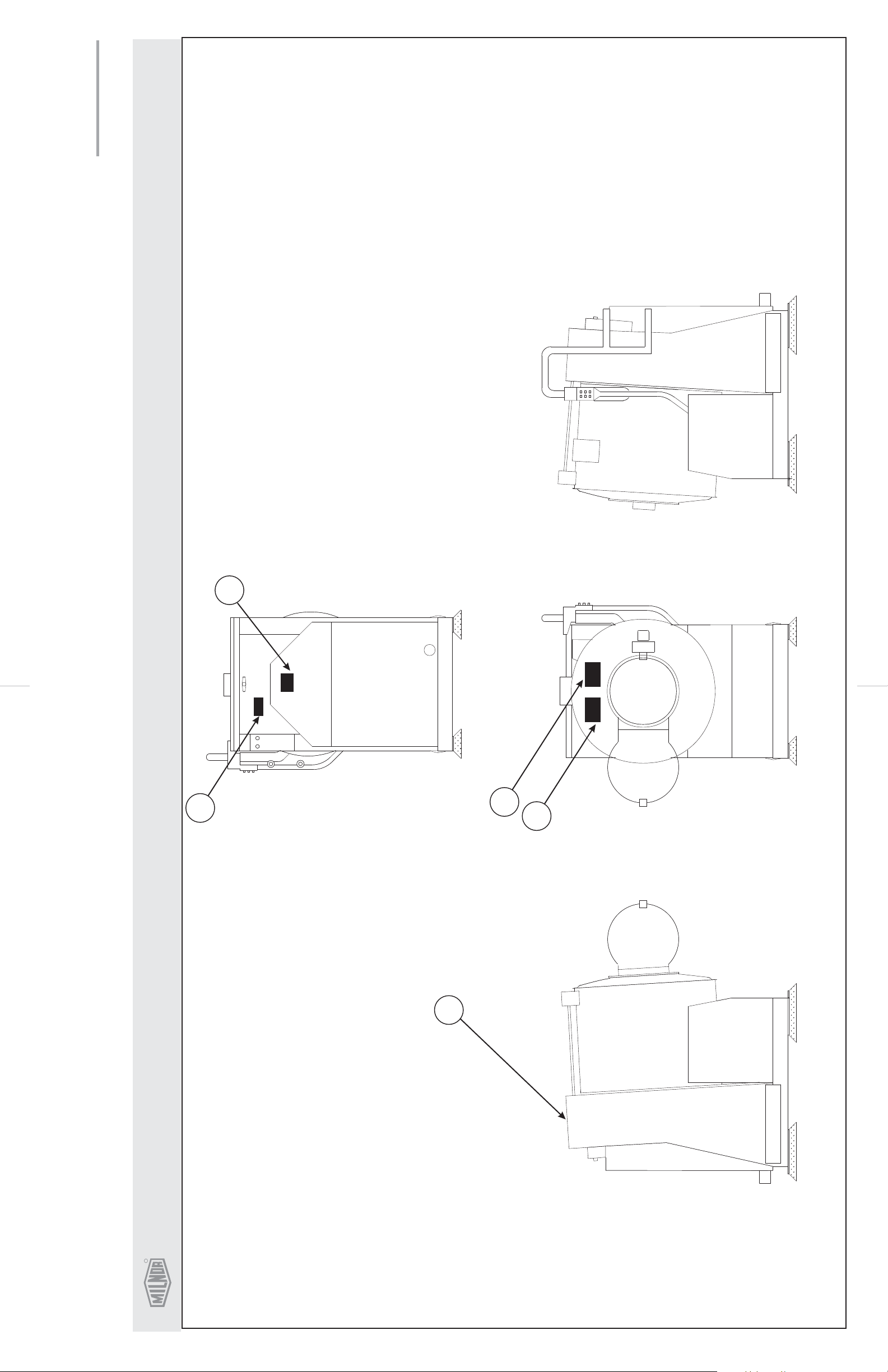
RIGHT VIEW
60
40
REAR VIEW
FRONT VIEWLEFT VIEW
10
50
P. O. Box 400, Kenner, LA70063-0400
Pellerin Milnor CorporationPellerin Milnor Corporation
R
unreadable.
. Replace placard immediately, if removed or
Notes:
1
Mounting holes are provided on machine.
If aluminum placard use #8 self-tapping screws.
. Approximate locations of placards are shown.
2
On Top
20
Safety Placard Use and Placement
36021CPE, NSP, V5J, V5Z & , V5Z36026V5J
23
R
Pellerin Milnor CorporationPellerin Milnor Corporation
P. O. Box 400, Kenner, LA70063-0400
BMP020109/2014356B
(Sheet 2 of 2)
Litho in U.S.A.
Find the correct assembly first, then find the needed components. The item letters (A, B, C, etc.) assigned to
Parts List—Safety Placard Placement
assemblies are referred to in the "Used In" column to identify which components belong to an assembly. The item
numbers(1,2, 3,etc.)assignedtocomponentsrelatethe partslisttothe illustration.
Used In
.
---------------------------------------------------------------------ASSEMBLIES------------------------------------------------------------------
-------------------------------------------------------------------COMPONENTS-----------------------------------------------------------------all 10 01 10635A NPLT:SHELL FRONT RIDGID-TCA TA
all 20 01 10375B NPLT:ELEC HAZARD SMALL-TCATA
all 40 01 10689A NPLT:BELT HAZARD SM TCATA
all 50 01 10699A NPLT:SERV HZRD-PLYEST-TCATA
all 60 01 10377A NPLT:ELEC HAZARD LG-TCATA
Item
Part Number
Description
none
Comments
24
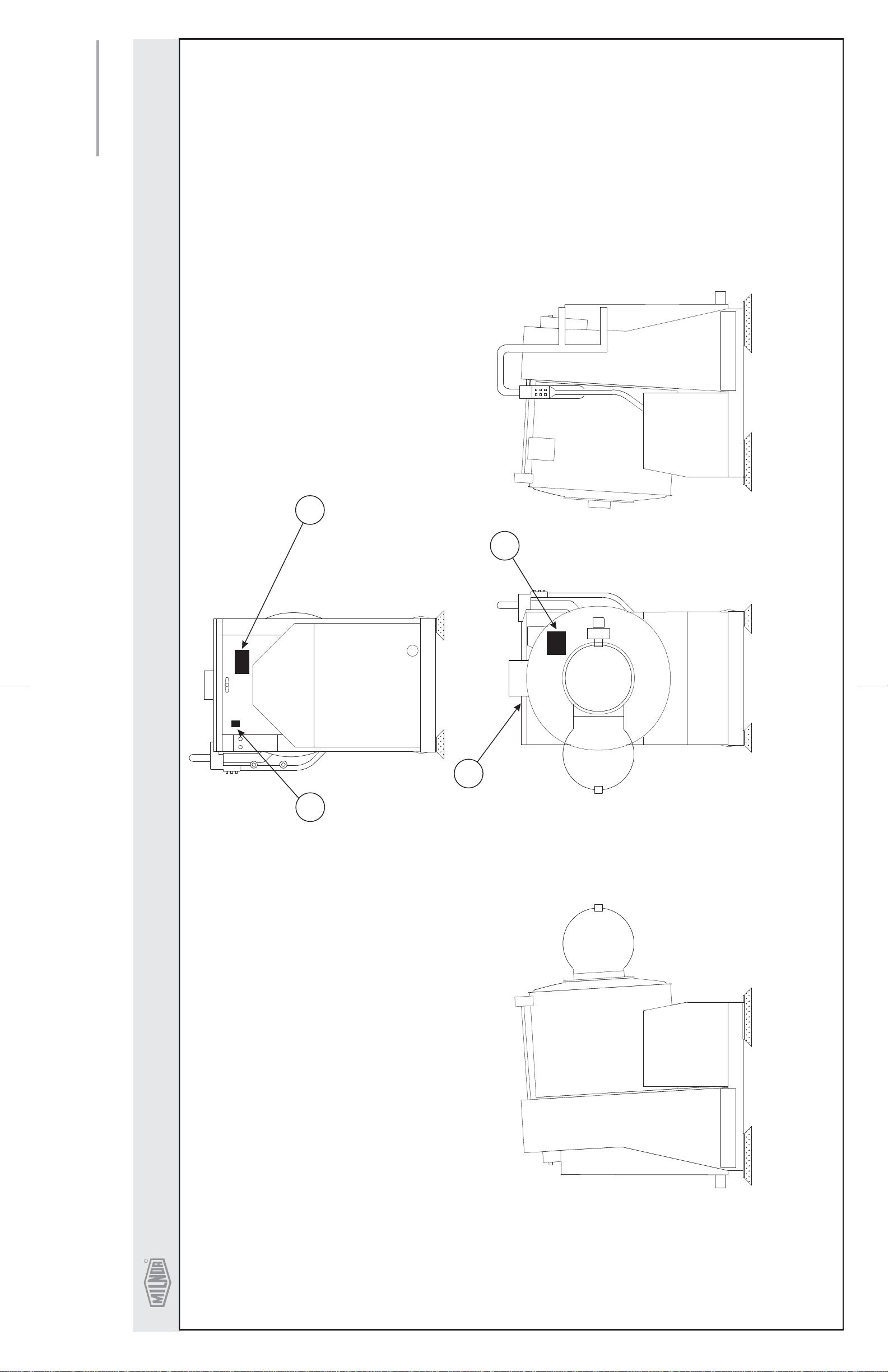
(Sheet 1 of 2)
BMP020110/2014356B
Litho in U.S.A.
10
30
REAR VIEW
20
40
FRONT VIEWLEFT VIEW RIGHT VIEW
Safety Placard Use and Placement ISO
36021CPE, NSP V5J, , V5Z & 36026V5J, V5Z
P. O. Box 400, Kenner, LA70063-0400
Pellerin Milnor CorporationPellerin Milnor Corporation
R
. Replace placard im-
Notes:
ISO Placards
shown on this page
1
mediately, if removed
of placards are shown.
or unreadable.
. Approximate locations
2
Mounting holes are
provided on machine.
If aluminum placard
use #8 self-tapping
screws.
25

R
Pellerin Milnor CorporationPellerin Milnor Corporation
P. O. Box 400, Kenner, LA70063-0400
BMP020110/2014356B
(Sheet 2 of 2)
Litho in U.S.A.
Find the correct assembly first, then find the needed components. The item letters (A, B, C, etc.) assigned to
Parts List—Safety Placard Placement
assemblies are referred to in the "Used In" column to identify which components belong to an assembly. The item
numbers(1,2, 3,etc.)assignedtocomponentsrelatethe partslisttothe illustration.
Used In
---------------------------------------------------------------------ASSEMBLIES------------------------------------------------------------------
-------------------------------------------------------------------COMPONENTS-----------------------------------------------------------------all 10 01 10632X NPLT:WE1 RIGID WARNINGS FR
all 20 01 10375 NPLTE:"W ARNING" 2X2
all 30 01 10377 NPLTE:"W ARNING" 4X4
all 40 01 10632Y NPLT:WE1 RIGID WARNINGS POL Y
Item
Part Number
Description
none
Comments
26
 Loading...