

Milnor 36026X8J, 42, 36, 42032X7J, 36026X8R Maintance Manual
...
Published Manual Number/ECN: MQMXBM01UU/2017264A
• Publishing System: TPAS2
• Access date: 06/28/2017
• Document ECNs: Latest
36026X8J, X8R, X8W
42026 & 42032X7J, X7R, X7W
PELLERIN MILNOR CORPORATION POST OFFICE BOX 400, KENNER, LOUISIANA 70063-0400, U.S.A.


MQMXBM01UU/17264A
1 1. English
3 Maintenance Guide—36- and 42-series, Rubber Spring-hung
Washer-extractor
35 2. Deutsch
37 Wartung—36- und 42-Serie, Waschschleudermaschine mit
Gummifederaufhängung
69 3. Português
71 Manutenção —Séries 36 e 42, Lavadora Extratora com
Suspensão
103 4. Français
105 Maintenance—Laveuse-essoreuse sur ressorts en
caoutchouc, séries 36 et 42
141 5. Español
143 Mantenimiento—Lavadora-extractora con sujeción por
muelles de goma, series 36 y 42
MQMXBM01EN/20120626
MQMXBM01DE/20120626
MQMXBM01PT/20120626
MQMXBM01FR/20120626
MQMXBM01ES/20120626


English 1
1

Published Manual Number: MQMXBM01EN
• Specified Date: 20120626
• As-of Date: 20120626
• Access Date: 20140801
• Depth: Detail
• Custom: n/a
• Applicability: MXB MXC MXD
• Language Code: ENG01, Purpose: publication, Format: 1colA
Maintenance Guide—
36- and 42-series,
Rubber Spring-hung
Washer-extractor
PELLERIN MILNOR CORPORATION POST OFFICE BOX 400, KENNER, LOUISIANA 70063 - 0400, U.S.A.
3

Applicable Milnor® products by model number:
36026X8J 36026X8R 36026X8W 42026X7J 42026X7R 42026X7W 42032X7J
42032X7R 42032X7W
4

Table of Contents
Table of Contents
Sections Figures, Tables, and Supplements
Chapter 1. Machine Description, Identification, and
Certification
1.1. About This Milnor® Machine—36- and 42-series, Rubber
Spring-hung Washer-extractor
1.1.1. Functional Description
1.1.2. Machine Identification Figure 1: Machine Data Plate
1.2. General Content of the EC-Declaration of Conformity
(Document BIWUUL01)
(Document BIUUUF01)
Chapter 2. Safety
2.1. Safety— (Document BIUUUS27)
2.1.1. General Safety Requirements—Vital Information for
Management Personnel
2.1.1.1. Laundry Facility
2.1.1.2. Personnel
2.1.1.3. Safety Devices
2.1.1.4. Hazard Information
2.1.1.5. Maintenance
2.1.2. Safety Alert Messages—Internal Electrical and
Mechanical Hazards
2.1.3. Safety Alert Messages—External Mechanical Hazards
(Document BIUUUS12)
2.1.4. Safety Alert Messages—Cylinder and Processing
Hazards
2.1.5. Safety Alert Messages—Unsafe Conditions (Document
BIUUUS14)
2.1.5.1. Damage and Malfunction Hazards
2.1.5.1.1. Hazards Resulting from Inoperative Safety
2.1.5.1.2. Hazards Resulting from Damaged Mechanical
2.1.5.2. Careless Use Hazards
2.1.5.2.1. Careless Operation Hazards—Vital Information
2.1.5.2.2. Careless Servicing Hazards—Vital Information
(Document BIUUUS13)
Devices
Devices
for Operator Personnel (see also operator hazards
throughout manual)
for Service Personnel (see also service hazards
throughout manuals)
(Document BIUUUS04)
(Document BIUUUS11)
2.2. Prevent Damage From Chemical Supplies and Chemical
Systems
(Document BIWUUI06)
PELLERIN MILNOR CORPORATION
5

Table of Contents
Sections Figures, Tables, and Supplements
2.2.1. How Chemical Supplies Can Cause Damage
2.2.1.1. Dangerous Chemical Supplies and Wash Formulas
2.2.1.2. Incorrect Configuration or Connection of Equipment Figure 2: Incorrect Configurations That
Let the Chemical Supply Go In the
Machine by a Siphon
Figure 3: Incorrect Configurations That
Let the Chemical Supply Go In the
Machine by Gravity
2.2.2. Equipment and Procedures That Can Prevent Damage
2.2.2.1. Use the Chemical Manifold Supplied. Figure 4: Examples of Manifolds for
Chemical Tubes. Your equipment can
look different.
2.2.2.2. Close the line.
2.2.2.3. Do not let a vacuum occur.
2.2.2.4. Flush the chemical tube with water.
2.2.2.5. Put the chemical tube fully below the machine inlet. Figure 5: A Configuration that Prevents
Flow in the Machine When the Pump
is Off (if the chemical tube and tank
have no pressure)
2.2.2.6. Prevent leaks.
Chapter 3. Routine Maintenance
3.1. Routine Maintenance—36- and 42-series, Rubber
Spring-hung Washer-extractor
3.1.1. How To Show the Maintenance On a Calendar Table 1: Where to Put Marks On a
3.1.2. Maintenance Summary Table 2: Guards and Related Components
3.1.3. How to Remove Contamination Table 8: Contamination Types, Cleaning
3.1.4. Lubricant Identification and Procedures Table 9: Lubricant Identification
3.1.4.1. Grease Gun Procedures
3.1.4.2. Procedures for Bearing Components Connected to a
Grease Plate
(Document BIUUUM09)
Calendar
Table 3: Filters, Screens, and Sensitive
Components
Table 4: Components that Become Worn
Table 5: Bearings and Bushings. See Table
6 for Motors.
Table 6: Motor Grease Schedule. Use the
data in Section 3.1.4.3 to complete this
table.
Table 7: Mechanisms and Settings
Agents, and Procedures
PELLERIN MILNOR CORPORATION
6

Table of Contents
Sections Figures, Tables, and Supplements
3.1.4.3. Procedures for Motors Figure 6: Motor Grease Maintenance
3.1.5. Maintenance Components—Machines and Controls
(Document BIUUUM10)
Group
3.1.6. Maintenance Components—Large Extractors (Document
BIWUUM03)
Conditions
Table 10: Motor Grease Intervals and
Quantities. Use grease EM (Table 9)
Supplement 1: How to Examine Belts and
Pulleys
Figure 7: Belt and Pulley Conditions To
Look For. See Supplement 1.
Figure 8: Electric Box and Inverter. These
are examples. Your machine can look
different.
Figure 9: Chemical Inlet Manifolds for
Chemical Pump Systems. See caution
statement 25 . These are examples.
Your machine can look different.
Figure 10: Soap Chute and Optional
5-compartment Supply Injector.
These are examples. Your machine
can look different.
Figure 11: Air Tube for the Water Level
Sensor. These are examples. Your
machine can look different.
Figure 12: Steam Inlet Strainer. These are
examples. Your machine can look
different.
Figure 13: Compressed Air Inlet Strainers.
These are examples. Your machine
can look different.
Figure 14: Grease Ports for Grease-only
Bearing Assembly
Figure 15: Suspension Components on
Each Side of Rubber Spring-Hung
Washer-extractors
PELLERIN MILNOR CORPORATION
7

Chapter 1. Machine Description, Identification, and Certification
Chapter 1
Machine Description, Identification,
and Certification
BIUUUF01 (Published) Book specs- Dates: 20120626 / 20120626 / 20140801 Lang: ENG01 Applic: MXB MXC MXD
1.1. About This Milnor® Machine—36- and 42-series, Rubber
Spring-hung Washer-extractor
This manual applies to the Milnor products whose model numbers are listed inside the front cover
and which are in the families of machines defined below.
1.1.1. Functional Description
Washer-extractors wash linen using water and nonvolatile chemicals and remove excess water
by centrifugal force.
Rubber Spring-hung Washer-extractor models are suspended washer-extractors with a
housing in which the shell hangs from rubber springs. These models are for use in OPL,
commercial, and industrial applications.
1.1.2. Machine Identification
Find the model number and other data for your machine on the machine data plate affixed to the
machine. See the figure that follows.
PELLERIN MILNOR CORPORATION
8
Chapter 1. Machine Description, Identification, and Certification
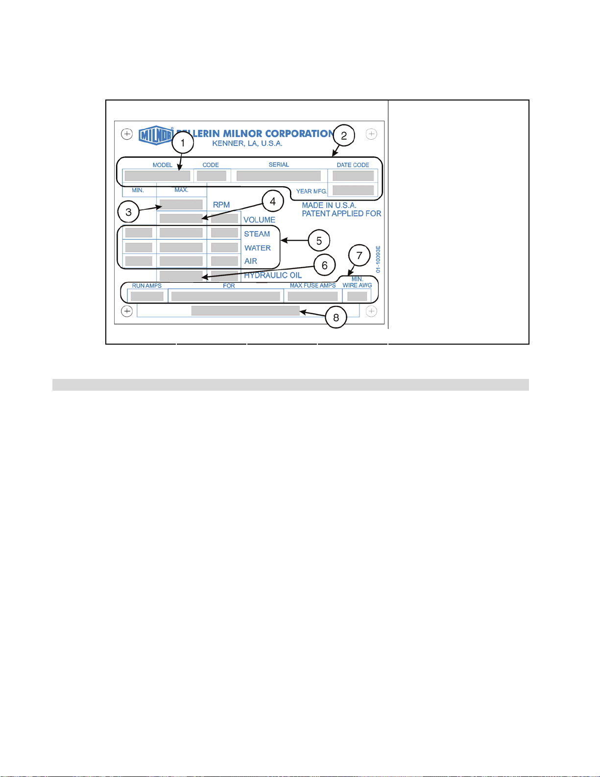
Figure 1: Machine Data Plate
View of Data Plate (English text shown) Legend
1. Model number. See
inside the front cover of
this manual.
2. Data that uniquely
identifies your machine
3. Cylinder maximum
rotation speed in
revolutions per minute, if
applicable
4. Cylinder volume in the
units of measure shown,
if applicable
5. Piped utility requirements
6. Hydraulic oil pressure, if
applicable
7. Electrical requirements
8. Part number for
.
multi-unit machine, if
applicable.
1.2. General Content of the EC-Declaration of Conformity
BIWUUL01 (Published) Book specs- Dates: 20120626 / 20120626 / 20140801 Lang: ENG01 Applic: MXB MXC MXD
— End of BIUUUF01 —
Manufacturer: Pellerin Milnor Corporation
Hereby we declare under our sole responsibility that the machinery
Type (see the declaration for your machine)
Serial no (see the declaration for your machine)
Manufacturing date (see the declaration for your machine)
is in conformity with the provisions of
2006/42/EC (17 May 2006) - Machinery
2004/108/EC (15 December 2004) - Electromechanical compatibility
2006/95/EC (12 December 2006) - Low voltage
Pellerin Milnor Corporation certifies that the machine(s) listed above, manufactured in Kenner,
Louisiana, 70063, USA conform(s) as stipulated by schedule of verification of
ISO 10472-1:1997 - Safety requirements for industrial laundry machinery - Part 1: Common
requirements
ISO 10472-2:1997 - Safety requirements for industrial laundry machinery - Part 2: Washing
machines and washer-extractors
ISO 13857:2008 - Safety of machinery - Safety distances to prevent hazard zones being
reached by upper and lower limbs
EN 61000-6-3:2007/A1:2011 - Emission standard for residential, commercial and
light-industrial environments
EN 61000-6-4:2007/A1:2011 - Emission standard for industrial environments
EN 60204-1:2006/A1:2009 - Safety of machinery - Electrical equipment of machines, Part
One, General requirements.
PELLERIN MILNOR CORPORATION
9

Chapter 1. Machine Description, Identification, and Certification
Safety compliance to the standard is described in detail in MILNOR manual (see the declaration
for your machine).
This letter confirms that the machine(s) only meets the required aforementioned standards. It is
the responsibility of the installer/owner of the machine(s) to ensure compliance with all
requirements for on-site preparation, installation, and operation.
Our conformance to the above listed standards is certified with exceptions listed in MILNOR
Conformance Report (see the declaration for your machine).
Place Kenner, Louisiana, 70063, USA
Date of first issue of above mentioned machine type
Signature Kenneth W. Gaulter Engineering Manager
Signature Russell H. Poy Vice President, Engineering
— End of BIWUUL01 —
PELLERIN MILNOR CORPORATION
10

Chapter 2. Safety
Chapter 2
Safety
2.1. Safety—
BIUUUS27 (Published) Book specs- Dates: 20120626 / 20120626 / 20140801 Lang: ENG01 Applic: MXB MXC MXD
2.1.1. General Safety Requirements—Vital Information for
Management Personnel
Incorrect installation, neglected preventive maintenance, abuse, and/or improper repairs, or
changes to the machine can cause unsafe operation and personal injuries, such as multiple
fractures, amputations, or death. The owner or his selected representative (owner/user) is
responsible for understanding and ensuring the proper operation and maintenance of the machine.
The owner/user must familiarize himself with the contents of all machine instruction manuals.
The owner/user should direct any questions about these instructions to a Milnor® dealer or the
Milnor® Service department.
Most regulatory authorities (including OSHA in the USA and CE in Europe) hold the owner/user
ultimately responsible for maintaining a safe working environment. Therefore, the owner/user
must do or ensure the following:
• recognize all foreseeable safety hazards within his facility and take actions to protect his
personnel, equipment, and facility;
• work equipment is suitable, properly adapted, can be used without risks to health or safety,
and is adequately maintained;
• where specific hazards are likely to be involved, access to the equipment is restricted to those
employees given the task of using it;
• only specifically designated workers carry out repairs, modifications, maintenance, or
servicing;
• information, instruction, and training is provided;
• workers and/or their representatives are consulted.
[Document BIUUUS04]
Work equipment must comply with the requirements listed below. The owner/user must verify
that installation and maintenance of equipment is performed in such a way as to support these
requirements:
• control devices must be visible, identifiable, and marked; be located outside dangerous zones;
and not give rise to a hazard due to unintentional operation;
• control systems must be safe and breakdown/damage must not result in danger;
• work equipment is to be stabilized;
• protection against rupture or disintegration of work equipment;
PELLERIN MILNOR CORPORATION
11

Chapter 2. Safety
• guarding, to prevent access to danger zones or to stop movements of dangerous parts before
the danger zones are reached. Guards to be robust; not give rise to any additional hazards; not
be easily removed or rendered inoperative; situated at a sufficient distance from the danger
zone; not restrict view of operating cycle; allow fitting, replacing, or maintenance by
restricting access to relevant area and without removal of guard/protection device;
• suitable lighting for working and maintenance areas;
• maintenance to be possible when work equipment is shut down. If not possible, then
protection measures to be carried out outside danger zones;
• work equipment must be appropriate for preventing the risk of fire or overheating; discharges
of gas, dust, liquid, vapor, other substances; explosion of the equipment or substances in it.
2.1.1.1. Laundry Facility—Provide a supporting floor that is strong and rigid enough to support–with
a reasonable safety factor and without undue or objectionable deflection–the weight of the fully
loaded machine and the forces transmitted by it during operation. Provide sufficient clearance for
machine movement. Provide any safety guards, fences, restraints, devices, and verbal and/or
posted restrictions necessary to prevent personnel, machines, or other moving machinery from
accessing the machine or its path. Provide adequate ventilation to carry away heat and vapors.
Ensure service connections to installed machines meet local and national safety standards,
especially regarding the electrical disconnect (see the National Electric Code). Prominently post
safety information, including signs showing the source of electrical disconnect.
2.1.1.2. Personnel—Inform personnel about hazard avoidance and the importance of care and
common sense. Provide personnel with the safety and operating instructions that apply to them.
Verify that personnel use proper safety and operating procedures. Verify that personnel
understand and abide by the warnings on the machine and precautions in the instruction manuals.
2.1.1.3. Safety Devices—Ensure that no one eliminates or disables any safety device on the machine
or in the facility. Do not allow machine to be used with any missing guard, cover, panel or door.
Service any failing or malfunctioning device before operating the machine.
2.1.1.4. Hazard Information—Important information on hazards is provided on the machine safety
placards, in the Safety Guide, and throughout the other machine manuals. Placards must be kept
clean so that the information is not obscured. They must be replaced immediately if lost or
damaged. The Safety Guide and other machine manuals must be available at all times to
the appropriate personnel. See the machine service manual for safety placard part numbers.
Contact the Milnor Parts department for replacement placards or manuals.
2.1.1.5. Maintenance—Ensure the machine is inspected and serviced in accordance with the norms of
good practice and with the preventive maintenance schedule. Replace belts, pulleys, brake
shoes/disks, clutch plates/tires, rollers, seals, alignment guides, etc. before they are severely
worn. Immediately investigate any evidence of impending failure and make needed repairs (e.g.,
cylinder, shell, or frame cracks; drive components such as motors, gear boxes, bearings, etc.,
whining, grinding, smoking, or becoming abnormally hot; bending or cracking of cylinder, shell,
frame, etc.; leaking seals, hoses, valves, etc.) Do not permit service or maintenance by
unqualified personnel.
PELLERIN MILNOR CORPORATION
12
Chapter 2. Safety
2.1.2. Safety Alert Messages—Internal Electrical and Mechanical
Hazards
The following are instructions about hazards inside the machine and in electrical enclosures.
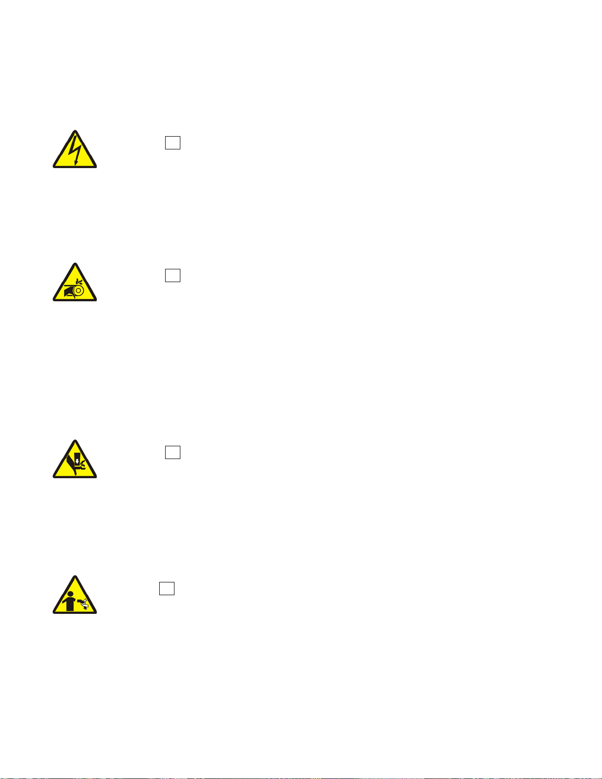
WARNING 1 : Electrocution and Electrical Burn Hazards—Contact with electric
power can kill or seriously injure you. Electric power is present inside the cabinetry unless the
main machine power disconnect is off.
• Do not unlock or open electric box doors.
• Do not remove guards, covers, or panels.
• Do not reach into the machine housing or frame.
• Keep yourself and others off of machine.
• Know the location of the main machine disconnect and use it in an emergency to remove
all electric power from the machine.
WARNING 2 : Entangle and Crush Hazards—Contact with moving components
normally isolated by guards, covers, and panels, can entangle and crush your limbs. These
components move automatically.
• Do not remove guards, covers, or panels.
• Do not reach into the machine housing or frame.
• Keep yourself and others off of machine.
• Know the location of all emergency stop switches, pull cords, and/or kick plates and use
them in an emergency to stop machine motion.
[Document BIUUUS11]
2.1.3. Safety Alert Messages—External Mechanical Hazards [Document
BIUUUS12]
The following are instructions about hazards around the front, sides, rear or top of the machine.
WARNING 3 : Crush Hazards —Suspended machines only—Spaces between the shell and
housing can close and crush or pinch your limbs. The shell moves within the housing during
operation.
• Do not reach into the machine housing or frame.
• Keep yourself and others clear of movement areas and paths.
2.1.4. Safety Alert Messages—Cylinder and Processing Hazards
[Document BIUUUS13]
The following are instructions about hazards related to the cylinder and laundering process.
DANGER 4 : Entangle and Sever Hazards —Contact with goods being processed can
cause the goods to wrap around your body or limbs and dismember you. The goods are normally
isolated by the locked cylinder door.
• Do not attempt to open the door or reach into the cylinder until the cylinder is stopped.
• Do not touch goods inside or hanging partially outside the turning cylinder.
• Do not operate the machine with a malfunctioning door interlock.
• Know the location of all emergency stop switches, pull cords, and/or kick plates and use
them in an emergency to stop machine motion.
• Know the location of the main machine disconnect and use it in an emergency to remove
all electric power from the machine.
PELLERIN MILNOR CORPORATION
13
Chapter 2. Safety
WARNING 5 : Crush Hazards —Contact with the turning cylinder can crush your limbs.
The cylinder will repel any object you try to stop it with, possibly causing the object to strike or
stab you. The turning cylinder is normally isolated by the locked cylinder door.
• Do not attempt to open the door or reach into the cylinder until the cylinder is stopped.
• Do not place any object in the turning cylinder.
• Do not operate the machine with a malfunctioning door interlock.
WARNING 6 : Confined Space Hazards—Confinement in the cylinder can kill or injure
you. Hazards include but are not limited to panic, burns, poisoning, suffocation, heat prostration,
biological contamination, electrocution, and crushing.
• Do not attempt unauthorized servicing, repairs, or modification.
WARNING 7 : Explosion and Fire Hazards—Fla mmable substances can explode or
ignite in the cylinder, drain trough, or sewer. The machine is designed for washing with water,
not any other solvent. Processing can cause solvent-containing goods to give off flammable
vapors.
• Do not use flammable solvents in processing.
• Do not process goods containing flammable substances. Consult with your local fire
department/public safety office and all insurance providers.
2.1.5. Safety Alert Messages—Unsafe Conditions [Document BIUUUS14]
2.1.5.1. Damage and Malfunction Hazards
2.1.5.1.1. Hazards Resulting from Inoperative Safety Devices
DANGER 8 : Entangle and Sever Hazards —Cylinder door interlock—Operating the
machine with a malfunctioning door interlock can permit opening the door when the cylinder is
turning and/or starting the cycle with the door open, exposing the turning cylinder.
• Do not operate the machine with any evidence of damage or malfunction.
WARNING 9 : Multiple Hazards—Operating the machine with an inoperative safety device
can kill or injure personnel, damage or destroy the machine, damage property, and/or void the
warranty.
• Do not tamper with or disable any safety device or operate the machine with a
malfunctioning safety device. Request authorized service.
WARNING 10 : Electrocution and Electrical Burn Hazards—Electric box
doors—Operating the machine with any electric box door unlocked can expose high voltage
conductors inside the box.
• Do not unlock or open electric box doors.
WARNING 11 : Entangle and Crush Hazards—Guards, covers, and panels—Operating
the machine with any guard, cover, or panel removed exposes moving components.
• Do not remove guards, covers, or panels.
PELLERIN MILNOR CORPORATION
14

Chapter 2. Safety
2.1.5.1.2. Hazards Resulting from Damaged Mechanical Devices
2.1.5.2. Careless Use Hazards
2.1.5.2.1. Careless Operation Hazards—Vital Information for Operator Personnel (see also
WARNING 12 : Multiple Hazards—Operating a damaged machine can kill or injure
personnel, further damage or destroy the machine, damage property, and/or void the warranty.
• Do not operate a damaged or malfunctioning machine. Request authorized service.
WARNING 13 : Explosion Hazards—Cylinder—A damaged cylinder can rip apart during
extraction, puncturing the shell and discharging metal fragments at high speed.
• Do not operate the machine with any evidence of damage or malfunction.
operator hazards throughout manual)
WARNING 14 : Multiple Hazards—Careless operator actions can kill or injure personnel,
damage or destroy the machine, damage property, and/or void the warranty.
• Do not tamper with or disable any safety device or operate the machine with a
malfunctioning safety device. Request authorized service.
• Do not operate a damaged or malfunctioning machine. Request authorized service.
• Do not attempt unauthorized servicing, repairs, or modification.
• Do not use the machine in any manner contrary to the factory instructions.
• Use the machine only for its customary and intended purpose.
• Understand the consequences of operating manually.
2.1.5.2.2. Careless Servicing Hazards—Vital Information for Service Personnel (see also
service hazards throughout manuals)
WARNING 15 : Electrocution and Electrical Burn Hazards—Contact with electric
power can kill or seriously injure you. Electric power is present inside the cabinetry unless the
main machine power disconnect is off.
• Do not service the machine unless qualified and authorized. You must clearly understand
the hazards and how to avoid them.
• Abide by the current OSHA lockout/tagout standard when lockout/tagout is called for in
the service instructions. Outside the USA, abide by the OSHA standard in the absence of
any other overriding standard.
WARNING 16 : Entangle and Crush Hazards—Contact with moving components
normally isolated by guards, covers, and panels, can entangle and crush your limbs. These
components move automatically.
• Do not service the machine unless qualified and authorized. You must clearly understand
the hazards and how to avoid them.
• Abide by the current OSHA lockout/tagout standard when lockout/tagout is called for in
the service instructions. Outside the USA, abide by the OSHA standard in the absence of
any other overriding standard.
WARNING 17 : Confined Space Hazards—Confinement in the cylinder can kill or injure
you. Hazards include but are not limited to panic, burns, poisoning, suffocation, heat prostration,
biological contamination, electrocution, and crushing.
• Do not enter the cylinder until it has been thoroughly purged, flushed, drained, cooled,
PELLERIN MILNOR CORPORATION
15

Chapter 2. Safety
and immobilized.
— End of BIUUUS27 —
BIWUUI06 (Published) Book specs- Dates: 20120626 / 20120626 / 20140801 Lang: ENG01 Applic: MXB MXC MXD
2.2. Prevent Damage From Chemical Supplies and Chemical
Systems
This document uses Simplified Technical English.
Learn more at http://www.asd-ste100.org.
All Milnor® washer-extractors and CBW® tunnel washers use stainless steel with the AISI 304
specification. This material gives good performance when chemical supplies are correctly applied.
If chemical supplies are incorrectly applied, this material can be damaged. The damage can be
very bad and it can occur quickly.
Chemical supply companies usually:
• supply chemical pump systems that put the supplies in the machine,
• connect the chemical pump system to the machine,
• write wash formulas that control the chemical concentrations.
The company that does these procedures must make sure that these procedures do not cause
damage. Pellerin Milnor Corporation accepts no responsibility for chemical damage to the
machines it makes or to the goods in a machine.
2.2.1. How Chemical Supplies Can Cause Damage
2.2.1.1. Dangerous Chemical Supplies and Wash Formulas—Some examples that can
cause damage are:
• a very high concentration of chlorine bleach,
• a mixture of acid sour and hypo chlorite,
• chemical supplies (examples: chlorine bleach, hydrofluosilicic acid) that stay on the stainless
steel because they are not quickly flushed with water.
The book “Textile Laundering Technology” by Charles L. Riggs gives data about correct
chemical supplies and formulas.
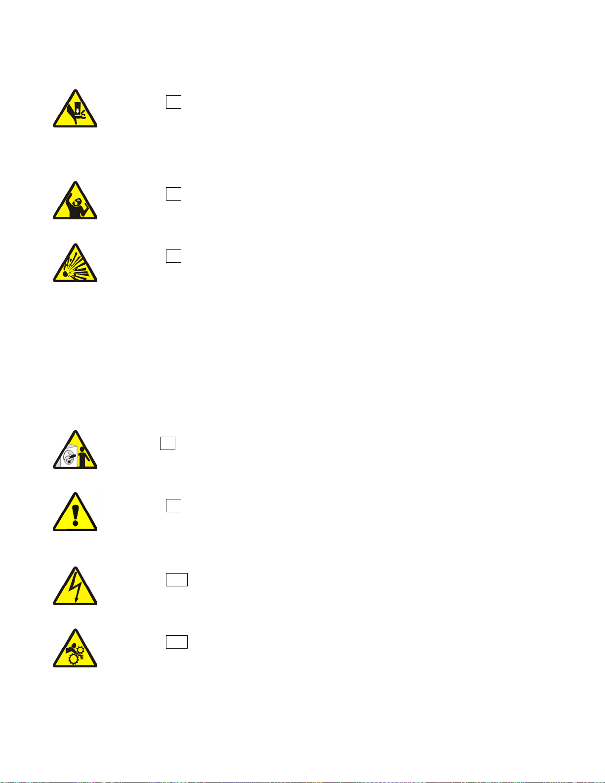
2.2.1.2. Incorrect Configuration or Connection of Equipment—Many chemical systems:
• do not prevent a vacuum in the chemical tube (for example, with a vacuum breaker) when the
pump is off,
• do not prevent flow (for example, with a valve) where the chemical tube goes in the machine.
Damage will occur if a chemical supply can go in the machine when the chemical system is off.
Some configurations of components can let the chemical supplies go in the machine by a siphon
(Figure 2). Some can let chemical supplies go in the machine by gravity (Figure 3).
PELLERIN MILNOR CORPORATION
16
Chapter 2. Safety
Figure 2: Incorrect Configurations That Let the Chemical Supply Go In the Machine by a Siphon
Schematic Views
Legend
P. Pump
T. Chemical tank
S. The siphon occurs above here. Liquid in the gray parts of the chemical tube and tank can go in
.
the machine.
PELLERIN MILNOR CORPORATION
17
Chapter 2. Safety
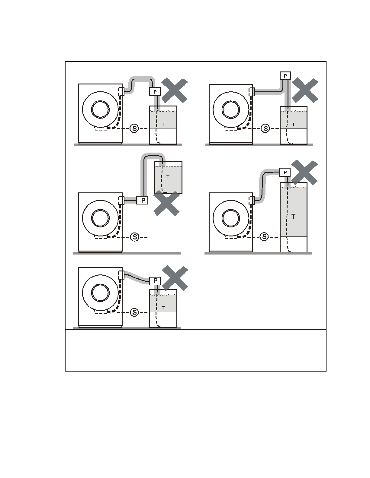
Figure 3: Incorrect Configurations That Let the Chemical Supply Go In the Machine by Gravity
Schematic Views
Legend
P. Pump
T. Chemical tank
D. Chemical tube. Liquid in the gray areas can go in the machine.
.
2.2.2. Equipment and Procedures That Can Prevent Damage
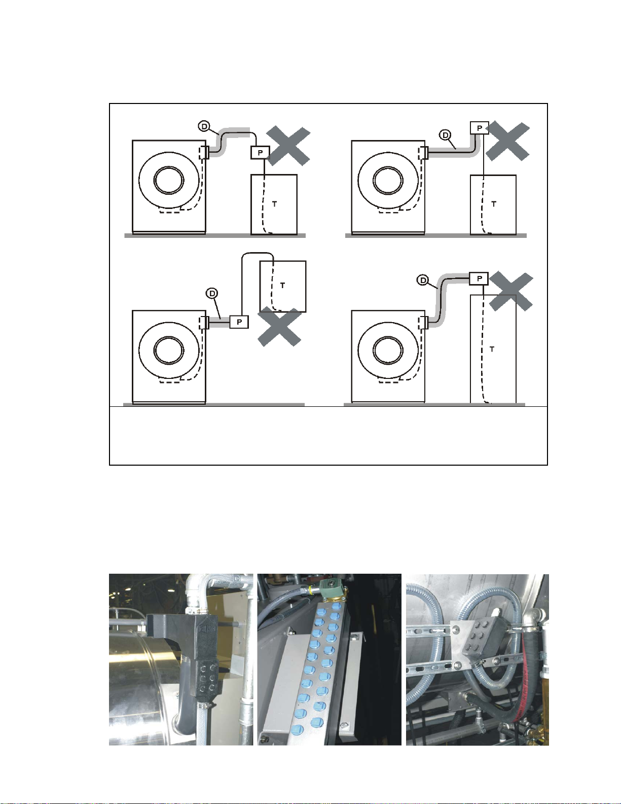
2.2.2.1. Use the Chemical Manifold Supplied.—There is a manifold on the machine to attach
chemical tubes from a chemical pump system. Figure 3 shows examples. The manifold has a
source of water to flush the chemical supplies with water.
Figure 4: Examples of Manifolds for Chemical Tubes. Your equipment can look different.
PELLERIN MILNOR CORPORATION
18
Chapter 2. Safety
2.2.2.2. Close the line.—If the pump does not always close the line when it is off, use a shutoff valve
to do this.
2.2.2.3. Do not let a vacuum occur.—Supply a vacuum breaker in the chemical line that is higher
than the full level of the tank.
2.2.2.4. Flush the chemical tube with water.—If the liquid that stays in the tube between the
pump and the machine can flow in the machine, flush the tube with water after the pump stops.
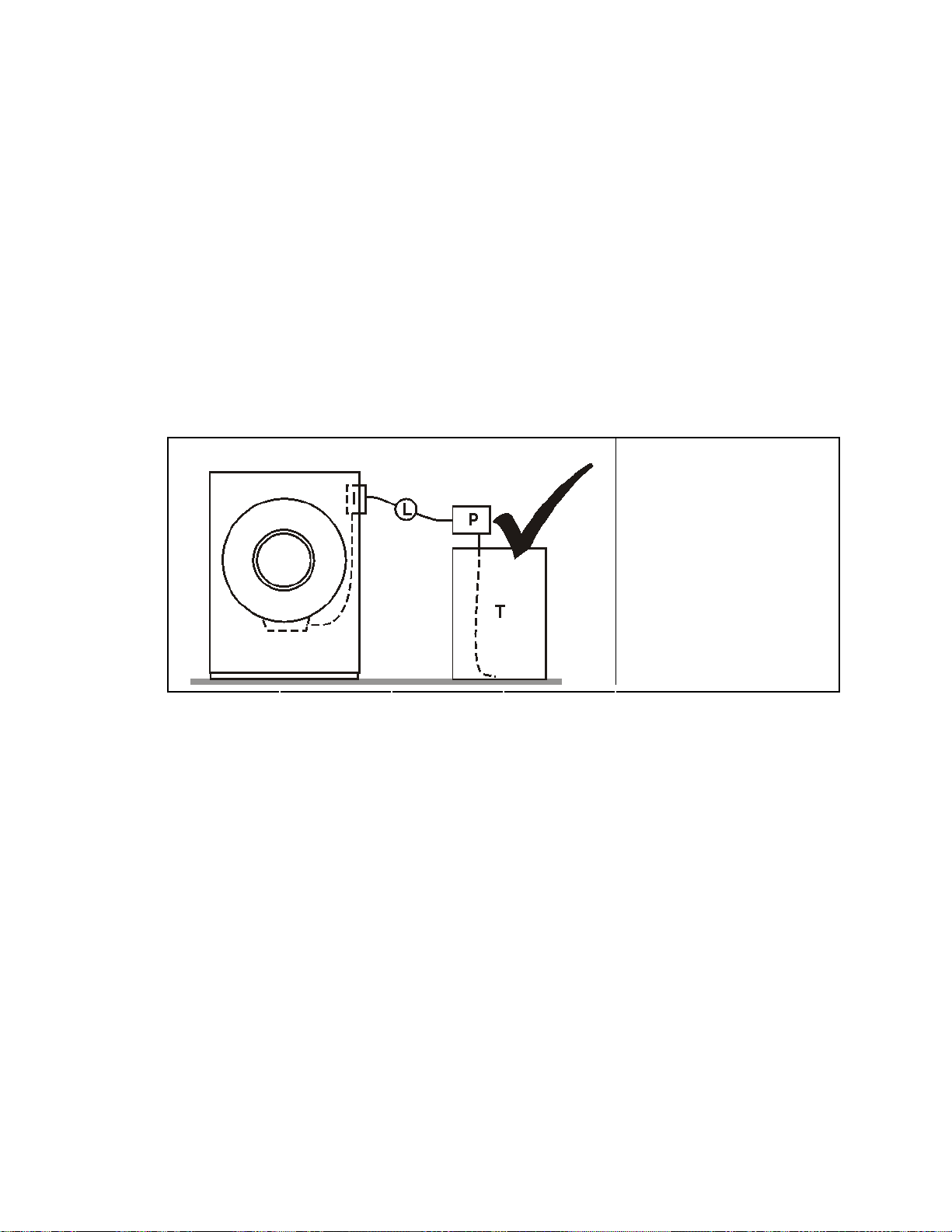
2.2.2.5. Put the chemical tube fully below the machine inlet.—It is also necessary that
there is no pressure in the chemical tube or tank when the system is off. Figure 5 shows this
configuration.
Figure 5: A Configuration that Prevents Flow in the Machine When the Pump is Off (if the chemical
tube and tank have no pressure)
Schematic View Legend
I. Chemical inlet on the
machine
L. Chemical tube
P. Pump
T. Chemical tank
.
2.2.2.6. Prevent leaks.—When you do maintenance on the chemical pump system:
• Use the correct components.
• Make sure that all connections are the correct fit.
• Make sure that all connections are tight.
— End of BIWUUI06 —
PELLERIN MILNOR CORPORATION
19
Chapter 3. Routine Maintenance
Chapter 3
Routine Maintenance
BIUUUM09 (Published) Book specs- Dates: 20120626 / 20120626 / 20140801 Lang: ENG01 Applic: MXB MXC MXD
3.1. Routine Maintenance—36- and 42-series, Rubber Spring-hung
Washer-extractor
This document uses Simplified Technical English.
Learn more at http://www.asd-ste100.org.
Do the maintenance in Section 3.1.2 “Maintenance Summary” to make sure that the machine is
safe, keeps the warranty, and operates correctly. This will also decrease repair work and
unwanted shutdowns. Speak to your dealer or Milnor if repairs are necessary.
WARNING 20 : Risk of severe injury—Mechanisms can pull in and mutilate your body.
• You must be approved by your employer for this work.
• Use extreme care when you must examine components in operation. Remove power from
the machine for all other work. Obey safety codes. In the USA, this is the OSHA
lockout/tagout (LOTO) procedure. More local requirements can also apply.
• Replace guards and covers that you remove for maintenance.
3.1.1. How To Show the Maintenance On a Calendar
If you use software to keep the maintenance schedule for your plant, add the items in Section
3.1.2 to that schedule. If not, you can put marks on a calendar that work with the tables in Section
3.1.2. The marks are the numbers 2, 3, 4, 5, and 6. It is not necessary to show the number 1 (items
you do each day) on the calendar. The number 2 = items you do each 40 to 60 hours, 3 = each
200 hours, 4 = each 600 hours, 5 = each 1200 hours, and 6 = each 2400 hours. These are the
"Mark" numbers at the top of the narrow columns on the left of each table in Section 3.1.2.
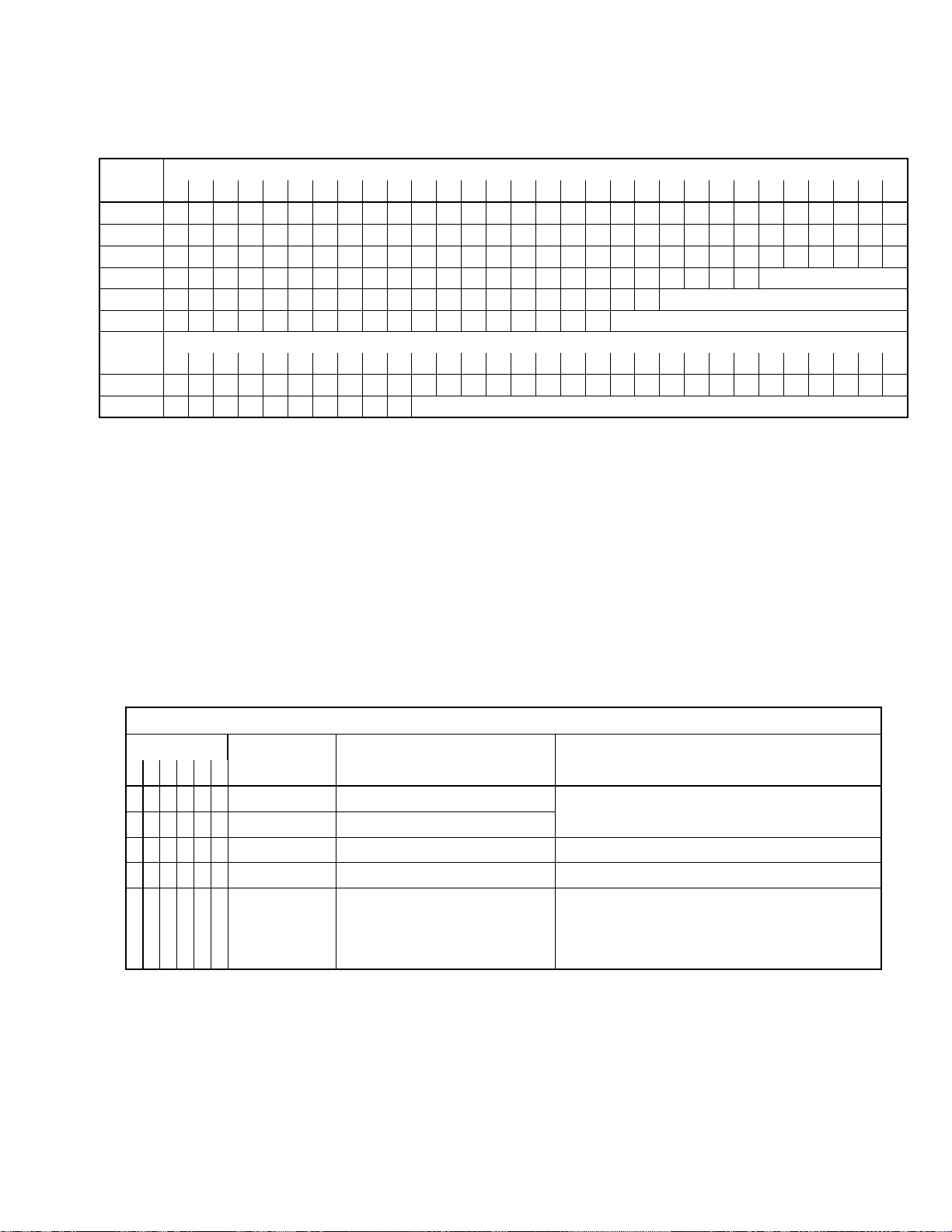
Table 1 shows where to put the marks on a calendar. For example, if your machine operates
between 41 and 60 hours each week, the first three marks are 2, 2, and 3. Put these marks on the
first, second, and third weeks after the machine starts operation. If you do routine maintenance on
a given day of the week, put the mark on that day of each week. Continue to put marks on the
subsequent weeks. It can be necessary to do the 40 to 60 hour (2) maintenance more than one
time each week. If the machine operates between 61 and 100 hours, put a 2 on two days of the
week. If the machine operates 101 or more hours, put a 2 on three days of the week.
On each date with a 3, do the items with an x in the 3 or the 2 column of each table in Section
3.1.2. On each date with a 4, do the items with an x in the 4, 3, or 2 column. Continue this
pattern.
PELLERIN MILNOR CORPORATION
20
Chapter 3. Routine Maintenance
Table 1: Where to Put Marks On a Calendar
Hours /
Week
Up to 40
41 - 60
61 - 80
81 - 100
101 - 120
121 - 140
Hours /
Week
Up to 40
41 - 60
2
3
4
5
6
7
8
1
2
2
2
2
2
2
3
3
3
32
2
2
3
3
2
2
2
33
2
3
2
2
2
2
2
31
2
2
3.1.2. Maintenance Summary
2
2
3
3
3
34
2
2
3
2
3
2
4
4
35
3
2
2
2
2
3
2
4
4
2
2
3
3
2
36
37
2
2
2
3
2
2
2
3
2
3
38
2
2
9
2
2
2
2
3
5
39
2
2
The tables in this section give the routine maintenance items for your machine. Each table is for
one type of procedure (example: apply grease to bearings and bushings). The top of the table
gives the general procedure. The "More Data" column gives special instructions if necessary.
10
3
4
3
3
5
2
40
3
6
Week Number
11
12
13
14
15
16
17
18
19
20
21
22
23
24
25
26
27
28
29
2
2
2
2
4
2
2
2
2
3
2
2
2
2
3
2
2
3
2
2
2
3
2
2
5
2
2
2
3
2
5
2
3
2
5
2
2
3
3
2
41
42
2
2
3
2
3
3
4
Week Number, continued
43
44
2
2
2
3
4
2
3
2
45
46
4
2
2
2
4
3
2
3
6
47
48
2
2
2
3
2
3
3
6
49
50
2
3
2
2
51
2
repeat
2
4
3
52
2
3
2
2
53
2
2
2
6
repeat
54
2
2
3
repeat
55
3
2
2
2
56
2
2
3
2
repeat
57
2
2
2
3
58
2
30
2
5
2
4
2
6
59
60
2
6
* If the machine operates more than 12 hours each day, do the "day" items two times each day.
Do the other items at the given hours or on the days that you show on a calendar (see Section 1).
Do all items in all tables for the maintenance intervals that apply (for example, day, 40 to 60
hours, and 200 hours).
Tip: The sections that follow the maintenance summary give more data about the maintenance items.
After you know this data, it is only necessary to look at the summary to do the maintenance.
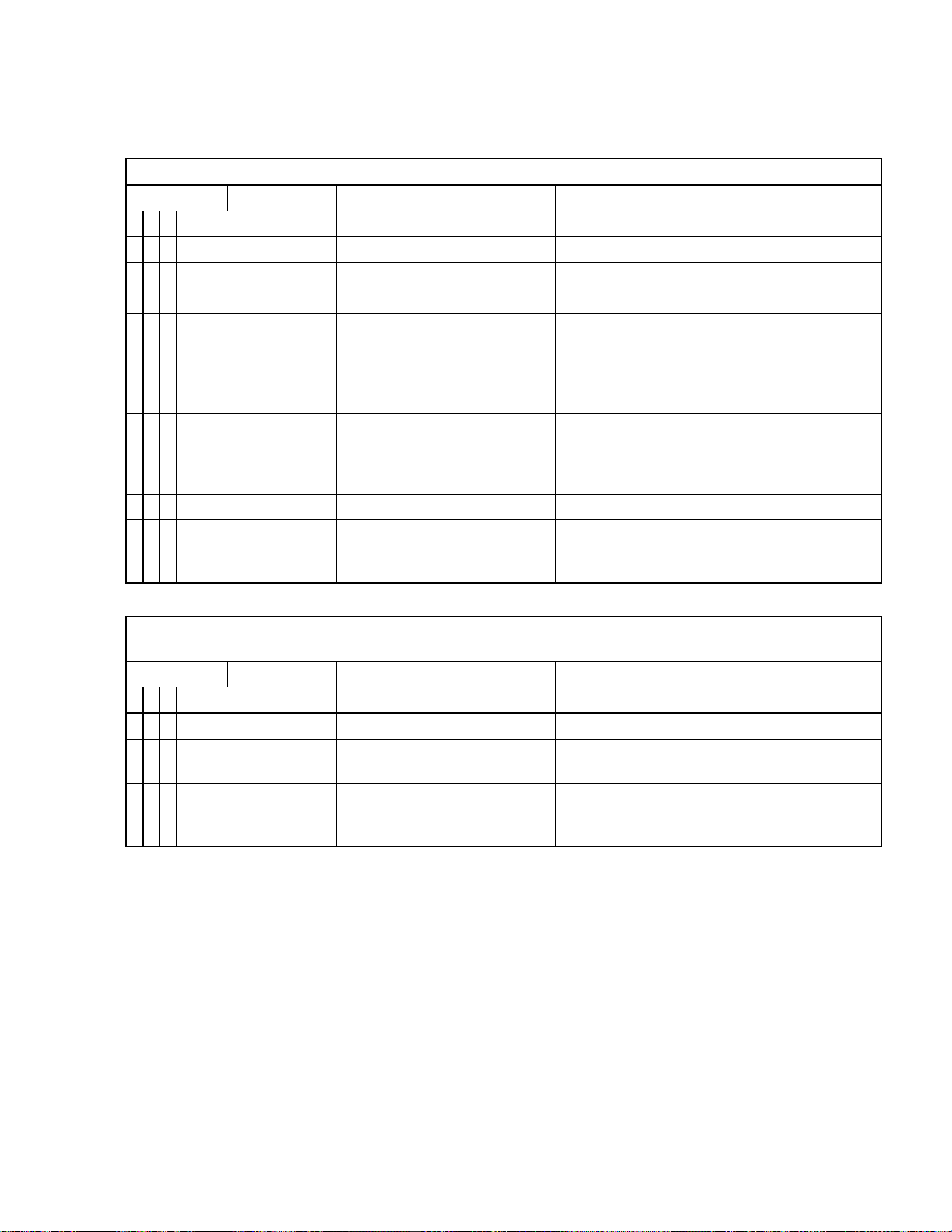
Table 2: Guards and Related Components
Examine. If a component is damaged, missing, or not set, correct this immediately to prevent injury.
Mark
2
3
x
x
4
1
x
x
x
5
6
Do this each
day*
day*
200 hours
200 hours
day*
guards, covers
safety placards
fasteners
anchor bolts and grout
door interlock
Component
More Data
Speak to your dealer or Milnor for
replacement components.
Fasteners must be tight.
Grout must be good. Bolts must be tight.
If the machine operates with the door open:
Immediately remove power.
Do not permit operation.
Speak to your dealer or Milnor.
PELLERIN MILNOR CORPORATION
21
Chapter 3. Routine Maintenance
Table 3: Filters, Screens, and Sensitive Components
Remove contamination from these components to prevent damage and unsatisfactory performance.
1
x
Mark
2
3
x
Do this each
4
x
5
6
40 to 60 hours
600 hours
x
2400 hours
day*
inverter fans, vents, filters
motors
entire machine
chemical inlet areas
Component
More Data. See also Section 3.1.3 “How
See Figure 8. Keep good air flow.
Keep good air flow.
Remove excessive dust and dirt.
to Remove Contamination”
Some chemical supplies that stay on machine
surfaces will cause corrosion damage. See
Figure 9 and Section 2.2. “Prevent Damage
From Chemical Supplies and Chemical
Systems”
x
2400 hours
strainer in water regulator for
optional supply injector and
See Figure 10
pumped chemicals on some
models.
x
x
200 hours
200 hours
Table 4: Components that Become Worn
strainer(s) for air inlet
strainer for steam inlet.
(Steam is optional on some
models.)
See Figure 13
See Figure 12
Examine. Tighten or replace if necessary, to prevent shutdowns and unsatisfactory performance.
1
Mark
2
3
x
x
x
Do this each
5
6
200 hours
200 hours
200 hours
4
Speak to your dealer for replacement parts
drive belts and pulleys
tubes and hoses
rubber springs and shock
absorbers
Component
See Supplement 1 and Figure 7
Examine hoses and hose connections for
leaks.
See Figure 15. It is necessary to replace worn
components. Speak to your dealer or Milnor.
This is not routine maintenance.
More Data
PELLERIN MILNOR CORPORATION
22
Chapter 3. Routine Maintenance
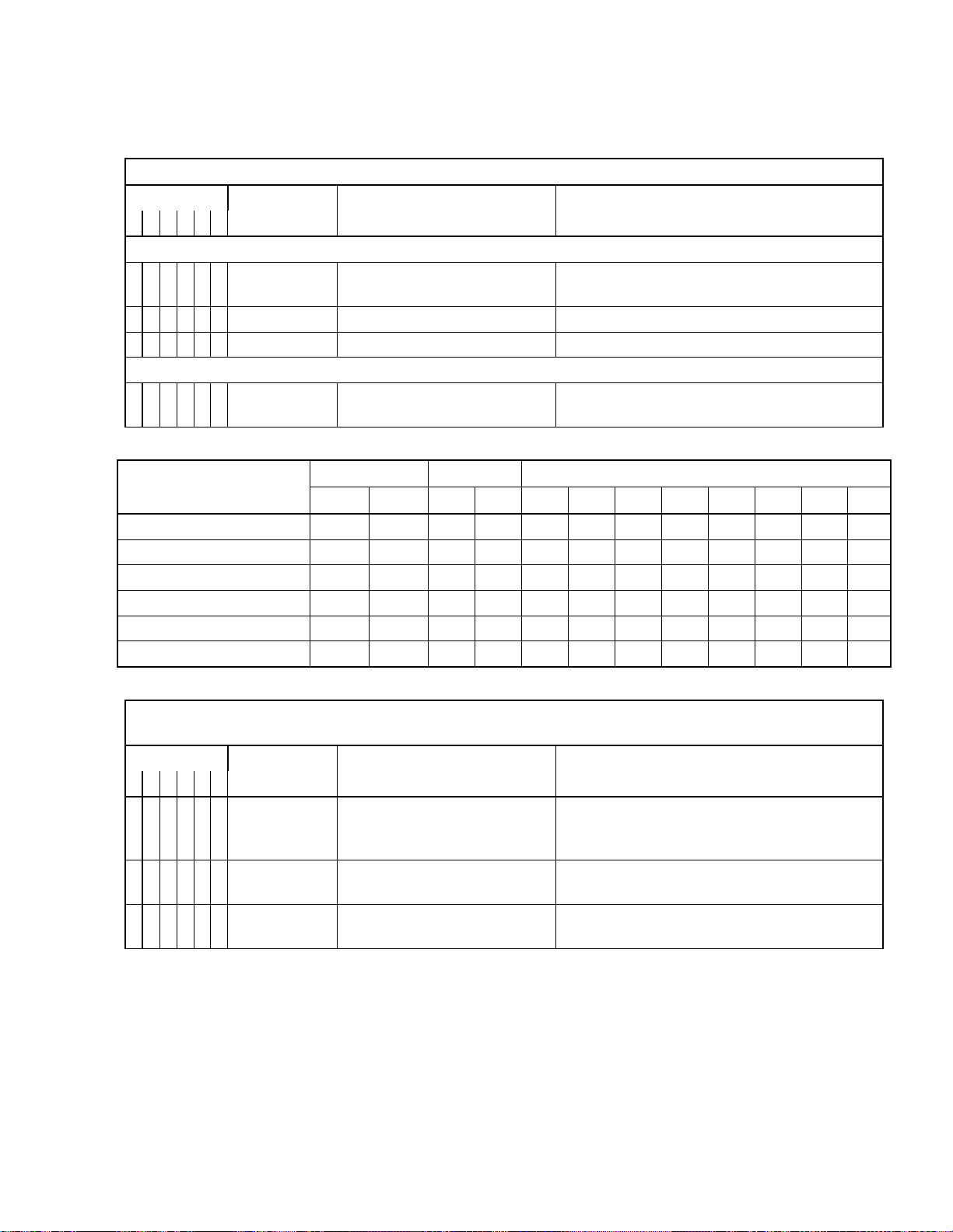
Table 5: Bearings and Bushings. See Table 6 for Motors.
Mark
2
3
4
x
x
x
x
1
Grease plate 01 10025Z for bearing housing. See Figure 14 and Section 3.1.4.2.
5
6
Do this each
200 hours
200 hours
200 hours
200 hours
Table 6: Motor Grease Schedule. Use the data in Section 3.1.4.3 to complete this table.
Motor Identification
(example: main drive)
Table 7: Mechanisms and Settings
Make sure mechanisms are serviceable and settings are correct to prevent unsatisfactory
Mark
1
2
3
x
x
4
5
6
x
Do this each
2400 hours
200 hours
200 hours
Apply grease to these components to prevent damage.
seal
rear bearing
front bearing
ball bushings on suspension
shafts
Interval
Years
controller circuitry
water pressure regulator for
optional supply injector
bath level sensor that uses air
pressure
Component
Hours
Component
Other Grease Ports
Quantity
fl oz
performance.
mL
More Data. See also Section 3.1.4
“Lubricant Identification and Procedures”
Add 0.06 oz. (1.8 mL) of grease EPLF2
(Table 9)
Add 0.12 oz. (3.6 mL) of grease EPLF2
Add 0.12 oz. (3.6 mL) of grease EPLF2
See Figure 15. Add 0.06 oz. (1.8 mL) of
grease EPLF2 (Table 9).
Dates When Grease is Added
Examine wiring and connections in electrical
boxes. Look for corrosion, loose connections.
See Section 3.1.3
See Figure 10. Value: 28 PSI (193 kPa).
Examine the air tube and connections. See
Figure 11
More Data
.
PELLERIN MILNOR CORPORATION
23

Chapter 3. Routine Maintenance
3.1.3. How to Remove Contamination
Table 8: Contamination Types, Cleaning Agents, and Procedures
Material or
Component
machine housing
fins and vents on
electrical
components
electric box interior
electrical
connections
electronic sensors
stainless steel
300 series stainless
steel
painted metal,
unpainted aluminum
rubber
clear plastic, acrylic
glass
soft air filter, lint
filter,
rigid strainers,
screens for water,
steam
rigid strainers,
screens for oil
Usual
Contamination
dust, dirt
dust
dust
corrosion,
varnish
dust
dirt
chemical spill
chemical
corrosive attack
dust, dirt, grease
dirt, oil, grease
discoloration
(yellowing)
discoloration
(yellowing)
dust, lint
mineral particles
metal shavings
Example
—
motors, inverters,
braking resistors
all electric boxes
spade connector,
molex connector,
plug-in relay
photoeye lens,
reflector, laser,
proximity switch,
temperature
probe
shell, supply
injector
shell interior,
cylinder
frame members
drive belts, hoses
compressed air
filter bowl, visual
flow meter
door glass, site
glass
on inverter
electric box door,
in air line filter
bowl, in dryers
in water line,
y-strainer
in hydraulic line
Cleaning Agent
compressed air or
shop vacuum
shop vacuum, soft
bristle brush, canned
air for electrical
components
spray solvent for
electrical components
none
warm water with
soap, then water flush
water
pickling and
passivation
warm water with
soap, then water to
flush
warm water with
soap, then water to
flush
warm water with
soap, then water to
flush, then acrylic
cleaner. Do not use
ammonia.
ammonia and water
solution and water
rinse then acetone
shop vacuum
water
carburetor cleaner or
equivalent solvent
Air—no more than 30 psi (207 kpa). Do not
push dust in mechanisms.
Do not push dust in mechanisms.
Disconnect then connect it again. Use solvent if
the bad connection continues.
Use a clean, soft, dry cloth.
Use clean, soft cloths.
Use a hose to flush the chemical supply from the
surface fully. Do not get water on electrical
components or mechanisms.
Speak to your dealer or Milnor.This is not
routine maintenance.
Use clean cloths. Do not get water in electrical
components.
Use clean cloths. Flush fully. Oil or soap must
not stay on drive belts. Make sure that drive
belts are serviceable.
Use only the necessary cleaning agents. Wash
and rinse with clean, soft cloths. Follow
instructions on acrylic cleaner.
Use clean, soft cloths. Use only the necessary
cleaning agents. If necessary, soak in cleaner.
Replace the used with a new filter when the
vacuum cannot remove contamination.
Use a rigid bristle brush. Flush with a flow of
water.
Soak. Use a rigid bristle brush.
More Data
3.1.4. Lubricant Identification and Procedures
Table 9 identifies the lubricant for each lubricant code given in the maintenance summary. Get
these or equivalent lubricants from from your local lubricant supplier.
PELLERIN MILNOR CORPORATION
24
Chapter 3. Routine Maintenance
When you add grease, always use the procedures given in Section 3.1.4.1. When you add grease
to motors, also use the procedures given in Section 3.1.4.3.
CAUTION 21 : Risk of damage—Bad lubricant will decrease the life of components.
• Make sure that all equipment and fittings used to apply lubricants are clean.
• Use only the given lubricants or equivalent lubricants that have the same specifications.
Table 9: Lubricant Identification
Code
EM
EPLF2
Type
grease
grease
Mobil Polyrex EM or as given on
the motor nameplate
Shell Alvania EP (LF) Type 2
Trademark Name
motor bearings
drive shaft bearings and bushings,
ball joints
Application Example
3.1.4.1. Grease Gun Procedures
CAUTION 22 : Risk of damage—Hydraulic pressure can push out seals and push grease
into unwanted areas (example: motor windings).
• Use a hand grease gun. A power grease gun gives too much pressure.
• Know the quantity of grease your grease gun gives each cycle (each stroke).
• Operate the grease gun slowly (10 to 12 seconds for one cycle).
• Add only the specified quantity. Stop if new grease come out of a drain port or other
opening.
• Remove spilled grease from belts and pulleys.
The tables give grease quantities in fluid ounces (fl oz) and milliliters (mL). You can also use
grease gun cycles (strokes). A cycle is each time that you pull the trigger. One cycle is usually
approximately 0.06 fl oz (1.8 mL). Your grease gun can give more or less than this. Measure the
output of your grease gun as follows:
1. Make sure that the grease gun operates correctly.
2. Operate the grease gun to put grease into a small container with fluid ounce or milliliter
increments. Pull the trigger fully and slowly.
3. Add a sufficient quantity of grease to measure accurately. Count the number of cycles of the
grease gun (the number of times that you pull the trigger).
4. Calculate the quantity for each cycle of the grease gun.
Example: 2 fl oz / 64 cycles = 0.031 fl oz for each cycle
Example: 59 mL / 64 cycles = 0.92 mL for each cycle
3.1.4.2. Procedures for Bearing Components Connected to a Grease Plate—Your
machine has a grease plate on the machine housing or the shell. You add grease to components of
the bearing housing at this location. The correct procedure is to add grease when the cylinder
turns at wash speed, but obey these precautions:
• For all other grease maintenance, add grease with power removed from the machine.
• If the grease plate on your machine is not serviceable (if you must add grease at a different
location), add grease with power removed from the machine.
• If you must remove a guard to get access to the grease plate, prevent access to the machine by
other personnel.
PELLERIN MILNOR CORPORATION
25

Chapter 3. Routine Maintenance
If you obey these precautions, use the Manual mode to operate the machine at wash speed. Then
add grease at the grease plate.
3.1.4.3. Procedures for Motors—If a motor on your machine does not have grease fittings, no
grease maintenance is necessary. If a motor on your machine has grease fittings, it is necessary to
add grease. But the interval is usually longer than for other maintenance. Table 10 gives motor
grease intervals and quantities for motors with specified frame sizes and speeds. You get this data
from the motor nameplate. Use Table 6 in Section 3.1.2 to record the data for the motors on your
machine.
PELLERIN MILNOR CORPORATION
26
 Loading...