

Page 1
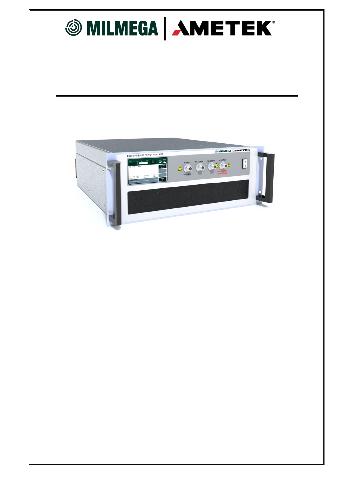
AS SERIES POWER AMPLIFIER
Manual number H012649
Any disclosure to third parties, or reproduction by any
means of any part of this manual without the written
Operation Manual
Revision: 1
First edition published 26th April 2018
consent of Milmega, is prohibited.
Page 2
For Sales
China
AMETEK Commercial Enterprise
(Shanghai) Co. Ltd.
Beijing Branch
Western Section, 2nd Floor
Jing Dong Fang Building (B10)
Chaoyang District
Beijing, China, 100015
T +86 10 8526 2111
chinasales@teseq.com
Shanghai Office:
Part A1, A4, 2nd floor, Building No. 1
No. 526 Fute 3rd Road East
Pilot Free Trade Zone, Shanghai 200131,
China
T +86 21 5868 5111
Guangzhou Office:
Room 1410-12, Yian Plaza
33 Jian She Liu Ma Road
Guangzhou, China
T +86 20 8363 4768
Germany
AMETEK CTS Germany GmbH
Lünener Straße 211
59174 Kamen, Deutschland
T +49 2307 26070-0
sales.cts.de@ametek.com
service.rf.cts@ametek.com
Great Britain
AMETEK CTS (UK)
Milmega
Park Road
Ryde
Isle of Wight PO33 2BE
Great Britain
T +44 1983 618004
milmega.sales@ametek.com
Japan
AMETEK Co. Ltd.
Tokyo office
3rd floor, Shiba NBF Tower,
1-1-30 Shiba-Daimon, Minato-ku
Tokyo, 105-0012, Japan
T +81 3 6809 2401
cts-japan.sales@ametek.com
Nagoya Office
1-329 Kifune Meito-ku Nagoya-shi
Aichi-ken, 465-0058, Japan
T +81 52 709 5501
Poland
AMETEK CTS Germany GmbH
Biuro w Polsce
ul. Ogrodowa 31/35
00-893 Warszawa, Polen
T +48 518 643 512
infopolska.cts@ametek.com
Singapore
AMETEK Singapore Pte. Ltd.
No. 43 Changi South Avenue 2
#04-01 Singapore 486164
T +65 6484 2388
singaporesales.cts@ametek.com
Taiwan
AMETEK Taiwan Corp. Ltd.
10F-5, No. 120, Sec 2,
GongDaoWu Rd.,
Hsinchu City 30072, Taiwan
T +886 3 57 5099
taiwan.sales.cts@ametek.com
USA
Teseq Inc. / AMETEK CTS
52 Mayfield Avenue
Edison, New Jersey 08837, USA
T +1 732 417 0501
Toll free: +1 888 417 0501
usasales.cts@ametek.com
usasupport.cts@ametek.com
AS Series Manual: H012649 Rev: 1
2
Page 3

Table of Contents
1.
INTRODUCTION 5
1.1
About this manual 5
1.2
Amplifier description 5
2.
SAFETY 6
2.1
General 6
2.2
Safety symbols and terms 6
2.3
Safety precautions 7
3.
INSTALLATION 9
3.1
General 9
3.2
Connecting the line cord 10
3.3
Connecting the chassis ground cable 10
3.4
Connecting the RF cables 10
3.5
Connecting the Safety interlock 10
4.
PROTECTION CIRCUITS 11
4.1 Over Heat Protection 11
4.2 Input Protection 11
4.3 Power Supply Faults 11
4.4
Mismatch Protection 11
5.
AMPLIFIER OPERATION 12
5.1
Safety interlock Operation 12
5.2
Switching on line supply 12
5.3 Cooling Fan Operation 13
5.4
General 13
5.5
Standby / RF On 13
5.6 Reset 14
5.7
Local 14
5.8 Gain Control 14
5.9
GPIB 15
6.
INDICATORS & FUNCTIONS 15
6.1
General 15
6.2 Touch Screen Indication 15
7.
CONNECTIONS 16
7.1
General 16
7.2
RF input, N Type connector 16
7.3
RF output N-Type or 7/16 (Model Dependent) 17
7.4
Sample Ports, N-TYPE Female 17
7.5
Line supply input connector 18
7.6
Safety interlock 18
7.7 IEEE-488 Convector 19
7.8
Ethernet 19
7.9
RS232 Connection 19
7.10 USB Connection 20
7.11 Ground post (8-32 thread) 20
AS Series Manual: H012649 Rev: 1
3
Page 4

8.
REMOTE CONTROL CONNECTIONS & OPERATIONS. 21
8.1
Connectors 21
8.2 IEEE 488 Operation 21
8.3 RS-232 Operation 21
8.4
Ethernet Connection 22
8.5 USB Connection 22
8.6
Remote Command Set 23
9.
ROUTINE MAINTENANCE 25
9.1
General cleaning 25
9.2
RF connectors 25
9.3
Air-filter cleaning. 25
10. FAULT FINDING 26
10.1 General checks 26
10.2 Fault indications 27
11. WARRANTY 29
11.1 Definitions 29
11.2 Scope 29
11.3 Terms and conditions 29
11.4 Transfer of Warranty 30
11.5 Protection of Warranty 30
11.6 Repair form 31
12. DECLARATION OF CONFORMITY 32
13. DRAWING SPECIFICATIONS 33
13.1 Fig 1, 4U front Panel & Outline Drawing 33
13.2 Fig 2, 7U Front Panel & Outline Drawing 34
14. DATASHEET SPECIFICATIONS 35
14.1 0.8 to 6.0GHz 30 Watts 35
14.2 0.8 to 6.0GHz 50 Watts 35
14.3 0.8 to 6.0GHz 100 Watts 35
14.4 0.8 to 6.0GHz 200 Watts 35
AS Series Manual: H012649 Rev: 1
4
Page 5

to install or operate the amplifier.
1. INTRODUCTION
1.1 About this manual
♦CAUTION! This Operation Manual contains important information for
the user of the amplifier. It details important safety information and
hazards that can be encountered by the user, and recommends
precautions that should be taken to prevent damage to the amplifier or
associated equipment. It is important that this Operation Manual
(including any information in the Appendices) is read before attempting
This operation manual contains information that details installation, routine
maintenance and amplifier operation. It does not contain information needed for
servicing or calibration.
1.2 Amplifier description
The Ametek CTS AS amplifier range is designed for laboratory use. The form factor
ranges from 4U and 7U bench top units up to rack mountable 16U or 20U amplifiers.
An AS series amplifier can be remotely controlled via the built in RS232, IEEE 488,
USB or Ethernet amplifier controller. Local control is via a front panel touch screen and
in addition also displays the amplifier status when controlled remotely.
A comprehensive performance and status indicating system is included. These
circuits monitor:
• Interlock circuit status
• Forward power indication
• Reflected power indication
• High VSWR indication
• RF baseplate temperature
• Ambient temperature
• Power supply DC voltage
• Power supply DC current
• Overall status of the amplifier
Visual indications are given. If a fault is detected, the amplifier automatically reverts
into a latched STANDBY condition. It remains in this condition until the fault has been
cleared and the fault latch is reset via the front panel touch screen.
The design of the amplifier is subject to continuous improvement. Consequently, the
amplifier may incorporate minor changes in detail from the information contained in
this manual.
AS Series Manual: H012649 Rev: 1
5
Page 6
manual that deals with a non
-
ionising radiation hazard.
inlet connector.
2. SAFETY
2.1 General
The amplifier described in this manual is designed to be used only by qualified
personnel. Use of the amplifier in a manner not specified in this manual may impair
the protection provided by the amplifier. Before use, inspect the amplifier for damage
which may impair safety.
There are no user-serviceable parts inside the amplifier, and any warranty is rendered
void if the seals on any covers are broken.
The following safety information is intended to protect all installers and operators, and
to prevent damage to the amplifier. It should be read and understood before installing
and operating the amplifier
2.2 Safety symbols and terms
♦CAUTION! statements identify conditions or practices that could result in damage to
the amplifier or other property.
♦WARNING! statements identify conditions or practices that could result in personal
injury or loss of life.
♦Note statements inform the user of important general information.
♦Hints and tips statements inform the user of useful information and operational
short cuts.
The following symbols appear on the amplifier and in this manual:
When used on the amplifier, warns the user of a non-ionising radiation
hazard. When used in this operation manual, alerts the user to the part of the
or
AS Series Manual: H012649 Rev: 1
When used on the amplifier, directs the user to refer to the operation manual.
When used in this operation manual, alerts the user to ♦WARNING! and
♦CAUTION! statements.
Warns personnel to observe correct lifting practices.
Ground terminal. Connect this terminal to a clean ground to improve EMC
immunity. Although it provides an extra measure of safety, this is not a
protective earth ground. The protective earth ground is the pin on the line
6
Page 7

2.3 Safety precautions
Observe all the following precautions to ensure personal safety and prevent damage
to the amplifier or equipment connected to it.
♦WARNING! Properly dispose of the amplifier.
The RF amplifier modules in this equipment contain Beryllium Oxide, and other
components contain PTFE. The appropriate precautions and regulations must be
observed concerning the disposal of this amplifier and certain internal components.
Do not crush or incinerate.
♦Note: Beryllium Oxide is a material used in the manufacture of RF devices. Toxic
dust is given off when crushed.
♦Note: PTFE is a material used in the manufacture of certain components within the
amplifier. PTFE gives off toxic gasses when incinerated.
♦WARNING! Do not touch the inner conductor of the RF-output connector.
High voltages can occur on the inner conductor of the RF output connector, or on
cables or antennas connected to it. These can cause RF burns if touched.
♦WARNING! Ground the amplifier.
The amplifier conforms with IEC Safety class 1, meaning that it is provided with a
protective grounding terminal. This is through the line supply cord to the centre pin of
the power inlet connector. To maintain this protection, the line supply cord must
always be connected to the source of line supply via a socket with a grounded contact.
Do this before making connections to the RF-input or RF-output connectors of the
amplifier.
Without the protective ground connection, all parts of the amplifier constitute a
potential shock hazard.
♦WARNING! Use the correct power cord.
Use only the line supply cord and connector specified for the amplifier. Use only a line
supply cord that is in good condition.
♦WARNING! Do not remove covers or panels.
To avoid personal injury, do not operate the amplifier without the panels or covers in
place.
♦WARNING! Do not operate in explosive atmospheres.
The amplifier provides no explosive protection from static discharges or arcing
components. Do not operate the amplifier in an atmosphere of explosive gasses.
AS Series Manual: H012649 Rev: 1
7
Page 8
Use the safety interlock facility within danger areas
.
♦CAUTION! Avoid static discharges
The RF input and output connections are static-sensitive and should not be subjected
to static discharge.
♦CAUTION! Use the correct line supply source
It is essential that the amplifier operates from a line supply source that does not apply
voltages and frequencies between the line supply conductors (or between either line
supply conductor and ground) that are outside the range detailed in the specification
sheet.
♦CAUTION! Do not obstruct the circuit breaker.
Ensure that there are no obstructions that impair the operation of the front panel line-
supply circuit breaker(s).
♦CAUTION! Do not obstruct the airflow through the amplifier.
The cooling airflow is drawn in through the front and exhausted at the rear. If this
airflow is obstructed, overheating of the amplifier may occur.
♦CAUTION! Do not operate the amplifier outside its specification.
This may cause the amplifier to malfunction or be damaged.
♦WARNING! Do not touch the exterior of the amplifier (rack mount version)
when in use.
The top and side panels of the amplifier can get hot during use, especially on high
power models.
♦CAUTION! Periodically replace the air-intake filters.
Operating the amplifier with the air filters dirty may cause the amplifier to overheat.
♦CAUTION!
or
Exercise caution when lifting.
The appropriate lifting practices should be observed during transportation, installation,
or removal of the amplifier from its mounting position.
♦WARNING!
Any area where personnel may come into direct contact with high power RF, or be
exposed to non-ionising radiation, should be designated as a danger area. A barrier
should be established around any such area, with a switch in place when the barrier is
broken. This switch can be linked to the safety interlock BNC connector on the
amplifier, thus disabling the amplifier when the barrier is breached. It is the
responsibility of the operator to ensure that the working environment is safe.
The ‘safety interlock’ feature is provided to assist the purchaser in establishing such a
‘safe’ area.
AS Series Manual: H012649 Rev: 1
8
Page 9

is operated in direct sunlight.
3. INSTALLATION
3.1 General
Amplifier models that are very heavy have a caution label on the top cover.
Appropriate lifting practices should be observed during transportation, installation, or
removal of the amplifier from its mounting position. When mounted in a rack, the
amplifier must not be supported by the front panel fixing holes alone. For easier
installation and removal, we recommend that the amplifier is positioned with its top no
more than 1.4 metres above ground level.
♦CAUTION!
or
♦CAUTION!
Do not support the whole weight of the amplifier with the front panel handles
Exercise care when lifting.
These should only be used for sliding the amplifier in and out on the rack.
♦Note: The amplifier may be lifted using the rear protection handles.
The amplifier is designed to be mounted in a 19 inch fixed rack installation. When
mounted in a rack, use a support tray-slider-assembly, especially for heavy amplifier
models. See the section 13 of this manual for details of amplifier dimensions.
♦CAUTION!
Do not obstruct the airflow through the amplifier.
At least 200mm clearance should be allowed behind the amplifier, so that air flow and
connecting cables are not obstructed. An unobstructed area of at least 200mm should
be allowed in front of the amplifier front panel air-intakes.
♦CAUTION!
Even though the ambient air temperature may be within the amplifier’s
specification, the internal temperature may rise above operational limits if it
The cooling airflow is drawn in through the front and exhausted at the rear. If this
airflow is obstructed, overheating of the amplifier may occur. For correct amplifier
operation, airflow through the unit must be maintained.
AS Series Manual: H012649 Rev: 1
9
Page 10

specification sheet.
panel line
-
input circuit breaker(s).
ground pin on the line supply connector(s).
connectors must not be used.
3.2 Connecting the line cord
♦CAUTION!
It is essential that the amplifier operates from a line source that does not
apply voltages and frequencies between the line conductors (or between
either line conductor and ground) that are outside the range detailed in the
♦CAUTION!
Ensure that the line cord does not interfere with the operation of the rear
3.3 Connecting the chassis ground cable
To improve EMC immunity, bond the amplifier to a good ground with a
conductor of 4 sq.mm or the equivalent earth braid, a ground post being
provided for this purpose on the rear panel. Although it provides an extra
measure of safety, this is NOT a protective earth. The protective earth is the
3.4 Connecting the RF cables
♦CAUTION!
Ensure that the RF source is OFF when making connections.
♦CAUTION!
Ensure any cables and connectors mating with the RF input and RF output
connectors are of 50-ohm impedance, and are designed to handle the power
at the frequencies generated by the amplifier. Although very similar, 75-ohm
Use cable with the lowest loss that is practical. The connectors should not be overtightened, and any tightening instructions for the connector should be observed.
Ensure that any bends in cables conform to the recommended minimum-bend-radius
of those cables, especially where the cables enter the RF connectors.
3.5 Connecting the Safety interlock
♦WARNING!
Use the safety interlock facility within danger areas.
If the amplifier is to be connected to an antenna, personnel may be exposed to nonionising radiation. In such systems, the safety interlock function should be used.
Connection (via the rear panel) is with a BNC-type connector. We recommend that
shielded cable is used for all interlock connections to ensure EMC immunity.
The current in the safety-interlock circuit is less than 1mA, so cable with a low current
capacity is suitable.
AS Series Manual: H012649 Rev: 1
10
Page 11
If you do not need this function, fit the supplied BNC shorting-link in place. Failure to
do this will result in the amplifier latching in an “Interlock Open” status which switches
the amplifier into standby mode.
4. PROTECTION CIRCUITS
4.1 Over Heat Protection
The AS series amplifier sub components produce heat and are air cooled by fans.
Should an over heat condition occur for any reason, the amplifer contains heat
sensors that will shut down the system via the amplifier control system. If the inlet and
outlet openings are obstructed, clear the obstruction and allow the amplifier to remain
in standby so that the internal fans can cool the amplifier down. Once the amplifier has
reached an acceptable temperature, depress the ”Fault Reset” soft key on the
touchscreen and the amplifier will operate normally.
4.2 Input Protection
The AS series is designed to achieve the specified output power level (see applicable
datasheet) for an input level of 0 dBm or less (1.0mW) however, to prevent overdriving
the amplifier, the Input Protection circuit will activate if the input signal exceeds 10
dBm and will automatically compensate for the increased input signal by reducing the
gain of the preamplifier. Even though the amplifier has an Input Protection Circuit,
overdriving the amplifier is not recommended.
IMPORTANT NOTE:
The amplifier Sample Port connectors must be either connected to a 50Ω
measurement system or terminated with the supplied 50Ω load. If the amplifier is
operated without 50Ω impedance on the Sample ports, the metering and output
protection may be inaccurate, which may result in damaging the amplifier and voiding
the unit’s warranty.
4.3 Power Supply Faults
The Power Supply Fault circuit monitors the voltage and current of system power
supplies and produces a fault indication should any voltage or current level deviate
from normal operating parameters. Each power supply voltage output is monitored
and displayed to indicate the power supplies are operating within design parameters.
4.4 Mismatch Protection
The amplifier is not damaged by using it into a load that has a poor 50Ω match. While
operating into a load that has a poor 50Ω match generating high VSWR the amplifier
can be driven at full power without requiring any input folded back or suffer any
damage.
AS Series Manual: H012649 Rev: 1
11
Page 12

before operating the amplifier.
RF input connector(s).
5. AMPLIFIER OPERATION
♦CAUTION!
Ensure that all the installation procedures detailed in Section 3 are complete
♦CAUTION!
Ensure that before connecting or turning the RF source ON, the input-source
peak output level is set to less than the maximum level detailed adjacent to the
5.1 Safety interlock Operation
♦WARNING!
Use the safety interlock function within danger areas.
Any area where personnel may come into direct contact with high power RF, or
be exposed to non-ionising radiation, should be designated as a danger area.
A barrier should be established around this area, with a switch opening when
the barrier is broken. This should be linked to the safety interlock connector,
disabling the amplifier when the barrier is breached. (It is the responsibility of
the operator to ensure a safe working environment).
Safety interlock connections are via a BNC connector on the rear panel. This should
be used with an appropriate switching or control arrangement so that the amplifier is
disabled when any barrier to a dangerous area is broken. Once the interlock
connection is broken the amplifier will default to standby mode. Once the interlock
connection is remade the interlock fault will clear and the amplifier will return to, “RF
Standby” mode. RF output will be resumed when the amplifier receives either a
manual (touch screen) or remote command instructing to amplifier to switch to, “RF
On” Mode.
5.2 Switching on line supply
After ensuring that the amplifier front panel rocker switch is in the down position (off)
ensure the mains lead is connected to the correct AC line source.
1 Switch the rear panel 3 phase circuit breaker to the “On” position. The rear
panel circuit breaker provides AC overcurrent protection. There will be no
amplifier indication as a result of this step.
2 Switch the front panel rocker switch to the Up (On) position. The touchscreen
will indicate that the boot up process has begun.
♦Hints and tips: This switch can remain in the ON position all the time, but it is best
set to OFF when the amplifier is not being used for long periods.
AS Series Manual: H012649 Rev: 1
12
Page 13
5.3 Cooling Fan Operation
Once the amplifier has been turned on, the power supply fan will start along with the
rear panel cooling fans. The AS series uses a forced air cooling system where air is
drawn in to the front grill and exhausted out of the rear of the amplifier. Temperature
sensitive fan circuits are used for optimal audible noise when the amplifier is in use.
When in standby mode the fans will operate at their slowest speed, once the amplifier
is set to, “Operate” mode, the RF modules will be enabled and start to generate heat.
The fans will slowly increase in speed until the amplifier has reached thermal
equilibrium.
♦Hints and tips: The air intake/exhaust should be kept clear at all times. If they are
blocked for any reason the amplifier will overheat and fault latch. Once the internal
amplifier temperature has cooled to within normal operating conditions the fault can be
reset and normal operation resumed.
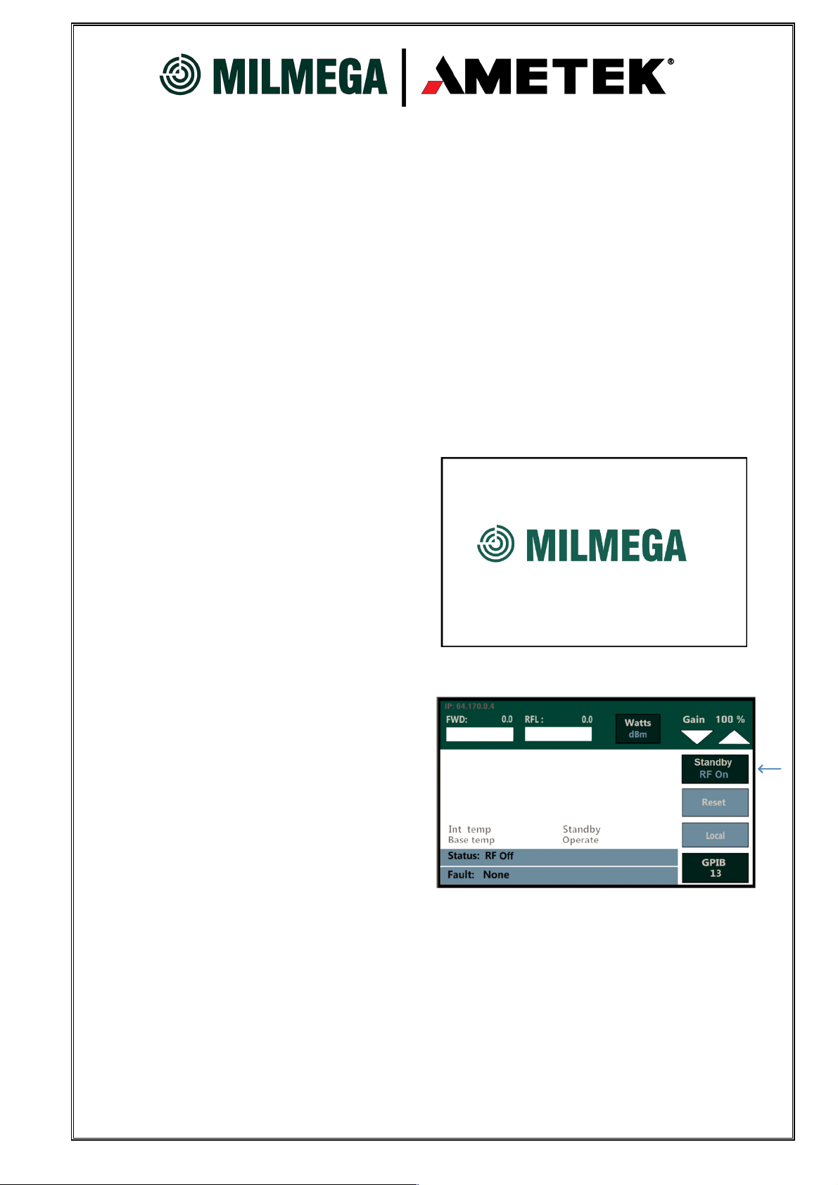
5.4 General
When the front panel rocker switch is
switched Up to the, “ON” position the
Milmega splash screen will appear on
the touch screen display. The amplifier
will remain in this state for a maximum
of 45 seconds while the amplifier
controller completes its boot sequence.
5.5 Standby / RF On
The “Standby / RF On” button controls
the RF On/Off function of the amplifier.
In standby the DC power supply is in
the, “Off” state and the amplifier is in
standby mode (RF Off).
Once pressed the, “RF On” will
illuminate white. This will indicate the
DC power supply has energised
supplying voltage to the power
modules and the amplifier is in, RF On mode
AS Series Manual: H012649 Rev: 1
13
Page 14

5.6 Reset
The “Reset” button will illuminate
Red when a fault is detected and
the amplifier returned to standby
mode. Once the fault is
removed/fixed depressing the
Reset button will clear the fault
indication so that normal operation
of the amplifier can resumed.
5.7 Local
When the amplifier receives a
remote command the remote
button will illuminate blue.
Depressing the button will restore
the amplifier to local operation
5.8 Gain Control
The gain control button allows for
gain adjustments over the entire
operating frequency of the
amplifier over a range of 20dB in
100 steps via the touch screen.
255 steps via the remote
command function.
AS Series Manual: H012649 Rev: 1
14
Page 15

Display
Indication
Display
Function
indication
reflected power in watts
2 PSU voltage and current
VDC PSU in Amps & Volts status
3 Internal Temperatures
Internal and baseplate temperature status
ho
urs
5 Status. Operate/Standby
Operate and standby indication
6 Fault status.
Thermal, PSU or Interlock fault status
5.9 GPIB
The GPIB address can be changed
by pressing the GPIB button.
Pressing the button will cycle
through the available addresses.
6. INDICATORS & FUNCTIONS
6.1 General
♦Note: The front panel touch screen shows the amplifier status for both local and
remote-control conditions.
6.2 Touch Screen Indication
Forward and reflected power
1
Hours of operation Elapsed time indication of STBY/OPRT
4
Mismatch load conditions as forward and
AS Series Manual: H012649 Rev: 1
15
Page 16

Front Panel
Rear Panel
Function
Comment
Function
Comment
Breaker
Breaker
Local/Remote Switch
interconnect.
RF On/Off Switch
Touch Screen
AC Power Connector
Fault/Reset Switch
Touch Screen
Interlock, BNC
Display Status
Gain Control,
Touch Screen
Ethernet
RS232
USB
Ground Post
Front or Rear Panel
RF Connectors
Function
Comment
RF I
nput & Output
Configuration Dependent
FWD/RFL Sample Ports
Configuration Dependent
zero.
7. CONNECTIONS
7.1 General
The AS series has an RF In, RF Out and a built in dual directional coupler with N-Type
forward and reflected connections. These are available in two configurations, either all
on the front or all on the rear of the amplifier. The AS series are equipped with either a
N-Type or a 7/16th RF output connecter (model dependent, see applicable datasheet)
but the same standard shall still apply; all RF connections are either on the rear or on
the front of the amplifier. The interlock, remote connections, AC connector, and
interconnecting cables are always located on the rear panel.
Summary
Amplifier Mains
Colour Touch Screen
7.2 RF input, N Type connector
3 Phase Main
Model Dependent
Amplifier Tray &
Touch Screen
PSU Tray DC Power
Model Dependent
Touch Screen IEEE 488, Connector
♦CAUTION!
The maximum input level detailed in the specification sheet and on the
amplifier front panel must not be exceeded. Do not expose the centre pin of
the RF-input connector to static discharge. The signal source must be at DC
Refer to the specification sheet for details of RF input levels. The nominal input
impedance is 50 ohms.
♦Hints and tips: Don’t forget that modulated or complex signals may have a peak
power that may not be indicated on the signal source. Always ensure that the peak
level of the input signal is within the limits specified in the applicable datasheet.
AS Series Manual: H012649 Rev: 1
16
Page 17

I
mpedance (ohms)
Level (Watts)
Level (dBc)
(dB)
50 <
700
46 +/- 3
50 > 700
50 +/- 3
Female N
-
Type RF Connector
Female 7/16 RF Connector
7.3 RF output N-Type or 7/16 (Model Dependent)
♦WARNING!
High RF voltages can occur on the inner conductor of the RF-out
connector, which could cause RF burns if touched. Do not expose
the centre pin to static discharge.
The nominal RF output impedance of the amplifier is 50 ohms, but it will safely drive a
load with an input impedance other than 50 ohms (resistive or reactive), but will deliver
less power. Refer to the specification sheet for details of RF output power.
7.4 Sample Ports, N-TYPE Female
These allow monitoring of both the incident power (Pi) and the reflected power (Pr)low
level. The nominal output impedance is 50 ohms, and each output should be
connected to a 50Ω test system or terminated with 50Ω load supplied with the
amplifier.
Nominal Output
Amplifier Power
Nominal Output
Flatness
The above parts can be supplied as spares or replacement items. The part number
must be quoted when ordering.
AS Series Manual: H012649 Rev: 1
17
Page 18

13A Power Conn
32A Power Conn’
Three Phase Star Distribution
Three Phase Delta Distribution
7.5 Line supply input connector
The As series amplifier power supply is equipped with a IEC or Neutrik Powercon inlet
for single phase models and a high current 3 phase, 5 wire Star configuration (184-264
VAC line to neutral) or 4 wire Delta configuration (184-264 VAC line to line) MS
connector for high power models. The amplifier systems are supplied with mating
power cords.
Rear Panel Single Phase
Rear Panel Single Phase
♦Note: Mains inlet connectors are model dependent.
7.6 Safety interlock
Rear Panel mounted BNC jack receptacle.
50Ω impedance.
+5 Volts (current limited)
This connector is supplied with a shorting-link for use when
the safety interlock function is not required.
AS Series Manual: H012649 Rev: 1
18
Page 19

Pin Signal
Pin Signal
Pin Signal
Pin Signal
7.7 IEEE-488 Convector
24 Way IEEE Bulkhead Connector.
1 Data IO1 13 Data IO5
2 Data IO2 14 Data IO6
3 Data IO3 15 Data IO7
4 Data IO4 16 Data IO8
5 End or Identify 17 Remote Enable
6 Data Valid 18 GND
7 Not Ready for Data 19 GND
8 No Data Accepted 20 GND
9 Interface Clear 21 GND
10 Service Request 22 GND
11 Attention 23 GND
12 Shield 24 GND Logic
7.8 Ethernet
RJ45 remote interface with signalling LED’s
1 Transmit (TX+)
2 Transmit (TX-)
3 Receive (RX+)
4 NC
5 NC
6 Receive (RX-)
7 NC
8 NC
7.9 RS232 Connection
Pin Female D-Type
1 Data Carrier Detected
2 Receive (RX)
3 Transmit (TX)
4 Data Terminal Ready
5 Signal Ground
6 Data Set Ready
7 Request to Send
8 Clear to send
9 Ring Indicator
AS Series Manual: H012649 Rev: 1
19
Page 20

Pin Signal
1 VDC (5V)
2 Receive (RX)
3 Transmit (TX)
7.10 USB Connection
USB-B device connector
4 Data Terminal Ready
7.11 Ground post (8-32 thread)
To improve EMC immunity, bond the amplifier to a clean ground with a
conductor of 4 sq.mm or the equivalent braid, to this post. Although it
provides an extra measure of safety, this is not a protective earth. The
protective earth is the ground pin on the line inlet connector.
AS Series Manual: H012649 Rev: 1
20
Page 21

8. REMOTE CONTROL CONNECTIONS & OPERATIONS.
8.1 Connectors
IEEE 488.2 24 Way IEEE connector
RS232 9 pin female D-type
LAN RJ45 with signalling LED’s
USB USB-B device connector
8.2 IEEE 488 Operation
The AS Series Amplifiers can be operated remotely from a computer having an IEEE488 interface. This interface allows the amplifier to be remotely controlled over the
General-Purpose Interface Bus (GPIB) by sending commands to the amplifier.
Additionally, amplifier status and forward and reverse power readings may be read
over the GPIB. All functions can be controlled by coded messages sent over the
interface bus via the 24-pin socket connector on the rear panel of the unit. The GPIB
command codes for the amplifier series are discussed on subsequent pages and, for
ease of identification; the command codes are identified within the text by bold capital
characters. For full information on the IEEE protocols and syntax the IEEE-488.2
Standard should be consulted
.
When the amplifier receives a command over the GPIB, it automatically switches to
REMOTE operation, pressing the LOCAL key on the front panel returns the unit to
normal manual local operation. The initial state of the amplifier after power-on is the
full attenuation condition.
♦Note: The ZEROATT command must be set in order for the amplifier to be able to
generate output power.
The GPIB address of the amplifier is set by via the Front panel using the touch screen
control button.
8.3 RS-232 Operation
For operation of the serial port a terminal application is required to be configured with
the following port configuration. Connect the RS232 cable and power the amplifier up.
♦Note: To determine which COM port is being used for a specific protocol, navigate to
CONTROL PANEL and double-click on the SYSTEM icon. Once under System
Properties, navigate to the HARDWARE tab and select DEVICE MANAGER. Scroll
down until you see PORTS (COM & LPT) and expand the drop-down menu. The
associated port should be listed.
♦Note: Ametek CTS doesn’t recommend the use of USB to serial adaptors unless the
adaptor contains an FTDI chip set.
AS Series Manual: H012649 Rev: 1
21
Page 22

RS-232 / USB Configuration Settings
RS-
232
USB
Bits per second
9600
9600
Data Bits
8 8
Parity
None
None
Stop Bits
1 1
Flow Control
None
None
STATIC IP
Y/N
STATIC IP Value
XXX.XXX.X.XX
SAVE SETTINGS
Y/N
Configure the selected Port as per the below settings.
To place the amplifier in remote operation type in a valid command such as
“STATUS”. The amplifier will then go into remote operation and the status will be
displayed on the computer.
8.4 Ethernet Connection
With the amplifier powered down connect via an Ethernet cable to the network. Power
the amp up and wait (5/10 seconds) for the amplifier to acquire an IP address
dynamically. The acquired IP address will then be displayed on the touch screen in the
top right-hand corner.
♦Note: The port number is 10001 and a DCHP server is required to address the
amplifier.
To assign a static IP to the amplifier, you must first establish a remote connection. Once
connected, type the command SETTINGS to enter the USER SETTINGS MODE. Once
in this mode, you can enter the command EDIT to begin configuring the static IP
settings. The EDIT SETTINGS VALUES are as follows:
8.5 USB Connection
♦Note: A USB cable with an FTDI chip set is required for this form of communication.
FTDI drivers are required to assign the USB interface a virtual com port. If these are
not installed on the PC in use they can be downloaded from,
http://www.ftdichip.com/FTDrivers.htm
Ensure the drivers are loaded and installed on the PC in use before connecting via
USB. With the amplifier powered down connect to the USB interface. Power the
amplifier up and the interface will be assigned a virtual com port. The COM Port
number can be discovered as per the RS232 method (8.3). Again, a terminal
application will be required to communicate with the amplifier using the same setting
as per the RS232 method (8.3)
AS Series Manual: H012649 Rev: 1
22
Page 23

Amplifier Status Commands
MODEL
Display Unit Model
SN
Display Unit Serial Number
*IDN?
Model, S/N, Firmware Version
*RST
Restarts the Amplifier
STATUS
Display Amplifier Status Message
FAULT
Display Amplifier Fault
RESET, RE
Reset Amplifier Fault
*SCREENSHOT
Takes a screenshot of the display
Amplifier Operate Commands
ON, OP, OPRT, RFOP, RFON
Turns the Amplifier On
OFF, STBY, OF, STB, RFOF
Turns the Amplifier Off
BAND_STATUS
Query Current Amplifier Band
BAND1
Switch to Band 1
BAND2
Switch to Band 2
Amplifier Pulse Commands
PULSEW
Display Pulse Width
DUTYCYC
Display Duty Cycle
FRQNCY
PERIOD
CW_ON
Switch to CW Operation
PLS_ON
Switch to Pulse Operation
PLS/CW_STATUS
Query current mode
Amplifier Temperature Metering Commands
Temperature
Temperature
Amplifier Elapsed Time Metering Commands
TOTALH
Total Amplifier ON Hours
OPERATEH
Total Amplifier OPERATE Hours
8.6 Remote Command Set
TEMP-BASE Query the Amplifiers Base Plate
TEMP-AMB Query the Amplifiers Ambient
AS Series Manual: H012649 Rev: 1
23
Page 24

Amplifier RF Power Metering Commands
POWERFWD
Report FWD Power (Watts)
POWERFWDDB
Report FWD Power (dBm)
POWERRFL
Report RFL Power (Watts)
POWERRFLDB
Report RFL Power (dBm)
RP
Report Power (FWD, RFL)
Amplifier Gain Control
GAIN
Display Gain Level
SETGAINxxx
Set specific gain level
ZEROATTN
Set Gain to 100%
FULLATTN
Set Gain to 0%
ATTUxxx
Attenuation Up
ATTDxxx
Attenuation
Amplifier Power Supply Metering Commands
PS1V
Power Supply 1 Voltage
PS1I
Power Supply 1 Current
PS2V
Power Supply 2 Voltage
PS2I
Power Supply 2 Current
PS3V
Power Supply 3 Voltage
PS3I
Power Supply 3 Current
PS4V
Power Supply 4 Voltage
PS4I
Power Supply 4 Current
Amplifier Power Supply Metering Commands
PAIALL
Display all PA Currents
PA
1I Module 1 Current
PA2I
Module 2
Current
PA3I
Module 3
Current
PA4I
Module 4
Current
PA5I
Module 5
Current
PA6I
Module 6
Current
PA7I
Module 7
Current
PA8I
Module 8 Current
IPAIALL
Display all IPA Currents
IPA1I
Intermediate
P
ower Module
1 Current
IPA2I
Intermediate
P
ower Module
2 Current
AS Series Manual: H012649 Rev: 1
24
Page 25

cleaning the RF connectors, as this seriously degrades their performance.
to
overheat.
9. ROUTINE MAINTENANCE
9.1 General cleaning
For cleaning the front panel, use an anti-static foam cleaner and a soft lint-free cloth or
tissue. Using abrasive materials or strong solvents may damage the surface finish or
the front panel overlay.
9.2 RF connectors
If the RF connectors are used frequently, or left disconnected for long periods, there is
a tendency for dirt and oxide deposits to build up. This increases the contact
resistance and creates localised heating of the RF OUT connector pin, which may
cause damage on high power models. Periodically inspect the inner pins of the RF
connectors for damage or deposits, and carefully clean if required.
♦CAUTION!
Do not use cleaning materials that leave a residue or that are abrasive for
When storing the amplifier for long periods, the RF connectors should be protected
with the plastic covers provided.
9.3 Air-filter cleaning.
♦CAUTION!
Operating the amplifier with the air-filter clogged, may cause the amplifier
The air-intake-filter on the amplifier front panel should periodically be checked for
cleanliness. If it is seen to be obstructed with any dust or debris this should be cleaned
away before the amplifier is operated.
AS Series Manual: H012649 Rev: 1
25
Page 26

10. FAULT FINDING
10.1 General checks
These are simple checks the user can perform to establish the cause of any amplifier
malfunction. The following procedures are by no means comprehensive, and do not
disclose any obscure fault with the amplifier or any system it may form a part of.
Amplifier Won’t Power Up at Mains Switch on.
• Ensure that the line cord is properly installed.
• Ensure that the line cord or connector is not damaged.
• Ensure that the 3-phase line circuit-breaker (model dependent) and front panel
rocker switch is switched on.
• Ensure that the line circuit-breaker is not in the tripped condition.
♦Note: If the line circuit-breaker trips, there is a fault with the power supply and the
amplifier must be returned to Milmega for repair. There are no user-replaceable fuses
in the amplifier.
No RF Output
• Ensure that the correct safety interlock signal is present. If the Interlock facility is
not used, ensure that the Interlock shorting-link (rear panel) is inserted.
• Ensure that the touch screen Operate/Standby button is illuminated green.
• Ensure that the RF cables and connectors are mated correctly.
• Ensure that there is no damage to any of the RF connectors or cables, especially
where the cable enters the connector.
• Ensure that the touch screen FLT/RST fault light is not illuminated red.
• Ensure that the RF input level is within specification.
RF present but at reduced level
• Ensure that the gain control is set to 100%
• Ensure that the RF cables and connectors are mated correctly.
• Ensure that the inner pins of the RF connectors are clean.
• Ensure that the RF load is 50 ohms.
• Ensure that there is no damage to any of the RF connectors or cables, especially
where the cable enters the connector.
• Ensure that the RF input level is within specification and that the gain adjustment is
set as expected.
♦Note: If the above checks have been done and the RF output is still at reduced level,
there is probably a fault with the RF modules, in which case the amplifier must be
returned to Milmega for repair.
AS Series Manual: H012649 Rev: 1
26
Page 27

Amplifier not responding to remote commands
• Ensure that the remote connector is mated properly.
• Ensure that the ‘REMOTE’ indicator is illuminated on the touch screen. If not, send
a, “OPRT” command.
• Ensure that there is no damage to the remote connector or cable, especially
around where the cable enters the connector.
10.2 Fault indications
HIGH VSWR
High VSWR is seen when high levels of output power are reflected into the amplifier.
The internal diagnostics determine if this state exists.
♦Note: The amplifier will not be damaged by using it with a high VSWR. It might be
that the load naturally has a poor VSWR – this just means that the full output power of
the amplifier cannot be delivered to the load. The function of the indication is not to
protect the amplifier. It is there to alert the operator that there has been a change in
the system operating conditions.
• Ensure that the RF cables and connectors are mated correctly.
• Ensure that the RF load is 50 ohms.
• Ensure that the inner pins of the RF connectors are clean.
• Ensure that there is no damage to any of the RF connectors or cables, especially
around where the cable enters the connector.
Interlock
Is indicated on the display in the amplifier status section when the continuity of the
safety interlock circuit is broken, or the interlock control signal is not present.
• Ensure that there is continuity through the safety interlock switch and wiring (if
used).
• Ensure that the safety interlock connector or shorting-link is properly mated.
• Ensure that the safety interlock control signal is present.
♦Note: If no external safety interlock switch or control signal is used, connect the
safety interlock shorting-link (rear panel).
Power Supply fault
When the power supply voltage or current is outside operational limits, a power supply
fault is illuminated and the system enters standby mode.
• Ensure that the power supply air-filter insert is not clogged or obstructed. Clean as
necessary.
• Ensure that the ambient temperature is within the amplifier specification.
• Ensure that there is at least the recommended clearance around the front and rear
panel air vents.
AS Series Manual: H012649 Rev: 1
27
Page 28

• Ensure that for amplifier models with multiple line-input connectors, all connectors
are connected to the line supply.
• Ensure that for models with more than one power supply, that all the rear panel
circuit breakers are set to the ON position.
♦Note: If the supply fault indicator is due to a high-temperature condition, cool the
power-supply by leaving the amplifier in, “STANDBY” mode. The power-supply
cooling fan (internal to the power-supply) can then reduce the power-supply
temperature. If the supply fault indicator remains illuminated when the power-supply
has cooled down, return the amplifier to Milmega for repair.
Thermal Fault
A thermal fault is indicated on the display in the amplifier fault section when the
temperature of the modules has risen above operational limits.
• Ensure that both rear panel fans are operating and not obstructed.
• Ensure that the air-filter inserts are not clogged or obstructed. Clean or replace if
necessary.
• Ensure that the amplifier is not operating in direct sunlight.
• Ensure that the ambient temperature is within the amplifier specification.
•
Ensure that there is at least the recommended clearance around the front and rear
panel air vents.
♦Note: To cool the RF modules down, leave the amplifier in the RF STANDBY
condition so the cooling fans can reduce the RF module temperature. If the fans are
not operating, or this indicator remains illuminated when the RF modules have cooled
down, return the amplifier to Milmega for repair.
If, after fault-finding, problems persist, contact Milmega by telephone, fax or E-mail. It
may be necessary to return the equipment to Milmega for repair. See the Appendix 2
for details on how to do this.
AS Series Manual: H012649 Rev: 1
28
Page 29

11. WARRANTY
Milmega Ltd. Warrants that this product is free from defects in materials and
workmanship for a period of:
• Five years on standard products
• one year on specifically designed products
11.1 Definitions
“Standard” means Milmega commercial product which, from time to time, appears in
its official marketing literature. It precludes product specifically designed to a customer
requirement.
11.2 Scope
Milmega warrants to the owner of any standard, AS Series, power amplifier product,
purchased from Milmega, its authorised dealers or resellers, that it will be free from
defects in material and workmanship for a period of 5 years from the date of original
shipment.
Should you encounter a problem within your first 5 years of ownership, we will have
the unit collected and guarantee to apply our reasonable endeavours to have it
repaired, and available for return, within 48 hours (6 working days) following receipt at
our facility. All costs associated with the activity will be borne by Milmega Ltd.
It is necessary for Customers to comply with the terms and conditions laid out below
so that they may enjoy the benefits of the warranty.
In order to obtain service under this warranty, the Customer must notify Milmega. (or
one of its agents) of the defect before the expiration of the warranty period, using the
‘Returns Form’ from this handbook (or a photocopy of it).
11.3 Terms and conditions
Milmega, or one of its authorised service centres, will, at its option, repair or replace
any unit or component covered by this warranty which becomes defective, or
malfunctions, under normal use / service during the period of this warranty, at no
charge for parts, labour or shipping to the owner.
Components, or units, replaced under the terms of the warranty shall continue to have
the benefit of the unexpired portion of the warranty only.
AS Series Manual: H012649 Rev: 1
29
Page 30

This warranty does not cover damage from customer accidents, misuse, abuse,
misapplication, operation with incorrect AC voltage, operation with faulty associated
equipment, unauthorised use by third parties other than the original customer,
modification or alteration without prior factory approval, service by an unauthorised
Service Centre and performance deterioration which will occur due to normal usage.
Units on which the serial number, or anti-tamper labels, has been removed or defaced
are not eligible for warranty service. Evidence of alteration, erasing, or forgery of
proof-of-purchase documents will be cause to void the warranty.
Units damaged due to the absence of routine maintenance, as defined by Milmega in
the product handbook, are not eligible for warranty service.
When product is to be returned for warranty service a return authorisation number
must first be obtained from Milmega. A description of the problem, as specific as
possible, should be attached to the request for the return authorisation number.
11.4 Transfer of Warranty
This warranty can be transferred to any new owner by informing Milmega within 30
days of ownership transfer.
Milmega may, at its discretion, request that the amplifier is first returned to the factory,
freight prepaid, to establish the condition of the amplifier and suitability for continuing
warranty cover. Failure to notify Milmega Ltd within 30 days will be cause to void the
warranty.
11.5 Protection of Warranty
To protect your warranty, we recommend you:
• Ensure the product is serviced in accordance with the guidance laid out in the
product handbook.
• Avoid unauthorised modifications to the product
Report any faults to Milmega, or the nearest authorised dealer, as soon as they
occur.
AS Series Manual: H012649 Rev: 1
30
Page 31

Milmega ltd
Teseq Inc / AMETEK CTS
Park Ro
ad 52 Mayfield Avenue
Ryde, Isle of Wight, PO33 2BQ
Edison, New Jersey, 08837, USA
Telephone: +4
4 1983 61800
4 Telephone: +1 732 417 0501
milmega.sales@ametek.com
usasupport.cts@ametek.com
11.6 Repair form
NAME OF DISTRIBUTOR: AMPLIFIER BEING RETURNED FROM:
MODEL No: SERIAL No:
RETURN OF EQUIPMENT TO Milmega
REPAIR DETAIL
PART No:
SHIPPING AGENT BEING USED: EXPECTED DATE OF ARRIVAL AT Milmega:
NATURE OF FAULT:
WHEN DID THE FAILURE OCCUR:
For Milmega Use Only:
Returns No:
Works Order No:
Please use this form for ALL amplifiers being returned for repair. Please give as many
details as possible.
AS Series Manual: H012649 Rev: 1
31
Page 32

12. DECLARATION OF CONFORMITY
Milmega Ltd., of Park Road, Ryde, Isle of Wight, as manufacturer and supplier of the
equipment specified below, hereby declare that the said equipment meets the intent of
Directive 2014-35-EU (Low Voltage Directive) and Directive 2014-30-EU
(Electromagnetic Compatibility) as defined by the standards listed below.
Date of Issue: 19th April 2016
Equipment type: High power, solid state amplifier, for industrial and laboratory
applications
Standards: BS EN 61326-1:2013
Electrical Equipment for Measurement, Control
And Laboratory Use – EMC Requirements
Class A
BS EN 61010-1:2011
Safety Requirements for Electrical Equipment For
Measurement, Control and Laboratory Use
Signed:
Mr Achim Gerstner, Managing Director
for and on behalf of Milmega Ltd.
AS Series Manual: H012649 Rev: 1
32
Page 33

13. DRAWING SPECIFICATIONS
13.1 Fig 1, 4U front Panel & Outline Drawing
AS Series Manual: H012649 Rev: 1
33
Page 34

13.2 Fig 2, 7U Front Panel & Outline Drawing
AS Series Manual: H012649 Rev: 1
34
Page 35

14. DATASHEET SPECIFICATIONS
14.1 0.8 to 6.0GHz 30 Watts
AS0860-30
14.2 0.8 to 6.0GHz 50 Watts
AS0860-50
14.3 0.8 to 6.0GHz 100 Watts
AS0860-100
14.4 0.8 to 6.0GHz 200 Watts
AS0860-200
AS Series Manual: H012649 Rev: 1
35
 Loading...