

Page 1

XLS/XLTTRANSDUCERS
S/
S
UC
S
Instruction Manual PL-522 January 2001
ER
D
33455220
Rev. 2.1
XLTTRAN
L
Page 2

Safety Guideline s
Warning notices must be obser ved to ensure personal safety as well as that of others, and to
protect the product and the connected equipment. These warning notice s ar e accomp anied
by a clarification of the level of caution to be observed.
Qualified Personnel
This device/system may only be set up and oper ated in conjunction with this manu al.
Qualified personn el ar e only authorized to insta ll and op erate this equipment in accordance
with established safety practices and standards.
Warning: This product can only function properly and safely if it is correctly transported,
stored, installed, set up , operated, and maintained.
Note: Always use p r od uct in accordance with specifications.
Copyright Siemens Milltronics Process
Disclaimer of Liability
Instruments Inc. 2000. All Rights Reserved
This document is available in bound version and in
electronic version. We encourage users to
purchase authorized bound manuals, or to view
electronic versions as designed and authored by
Siemens Milltronics Process Instruments Inc.
Siemens Milltronics Process Instruments Inc. will
not be responsible for t he contents of partial or
whole reproductions of eit her bound or electronic
versions.
MILLTRONICS®is a register ed trademark of Siemens Milltronics Pr ocess Instruments Inc.
Contact SMPI Technical Publications at the following address:
Technical Publicat ions
Siemens Milltronics Process Instruments Inc.
1954 Technology Drive, P.O. Box 4225
Peterborough, Ontari o, Canada, K9J 7B1
Email: techpubs@milltronics.com
While we have verified the contents of
this manual for agreement w it h t h e
instrumentation described, variations
remain possible. Thus we cannot
guarantee full agreement. The
contents of this manual are regularly
reviewed and corrections are included
in subsequent editions. We welcome
all suggestions for improvement.
Technical data subject to change.
For the library of SMPI instr uction manuals, visit our Web site: www.milltronics.com
© Siemens Milltronics Process Instruments Inc. 2001
Page 3

Table of Contents
Table of Contents....................................................................................3
Specifications..........................................................................................5
About the Transduce r..............................................................................7
General Guid e lines.............................................................................8
Outline and Dimensions ..........................................................................9
Mounting................................................................................................11
Recommendations............................................................................11
Solids Applications............................................................................11
Liquid App lications............................................................................12
Interconnection......................................................................................13
Recommendations............................................................................14
Applications...........................................................................................15
Solids...............................................................................................15
Liquids..............................................................................................16
Maintenance...........................................................................................18
Installation Diagrams.............................................................................19
Connection Diagram .........................................................................19
Interconnection Diagram ...................................................................20
PL-522 XLS/XLT Series Transducers Page 3
Page 4

Page 4 XLS/XLT Series Transducers PL-522
Page 5

Specifications
Beam Angle
• 5°
Environmental
Location
• indoor / outdoor
Altitude
• 2000 m maximum
Pollution Degree :
• 4
Ambient Pressure:
• 800 kPa (8 Bar, 120 PSI)
Construction
Exposure
• aluminum, 304 stainless steel and silicone
Mounting
• 1" NPT conduit connection
Cable
• 2 wire sh ielded / t wisted, 0. 5 m m2 (2 0 AWG)
Specifications
Supply Source
•
transdu c er s h a ll only be supplie d by Millt ro nic s ce rt ified controller s
Separation :
• 365 m (1200 ft) from t r ansducer
Approvals :
• CE
• see nameplate or consult Milltr onics for current approvals
1,
CSA, FM, SIRA/CENELEC
1
EMC perf ormanc e av ai lable up on r e qu es t
PL-522 XLS/XLT Series Transducers Page 5
Page 6

XLS - 60
Measurement Range
• 1.8 – 60 m (6 - 200 ft)
Frequency
• 13 kHz
Environmental
Specifications
Ambient Temp
• – 40 to 90 °C (– 40 to 195 °F )
Construction
Cable
• PVC jacket
Weight
2
• 4.3 kg (9.5 lb)
XLT - 30
Measurement Range
• 0.9 - 30 m (3 - 100 ft)
Frequency
• 22 kHz
Environmental
Ambient Temp
• – 40 to 150 °C ( – 40 to 300 °F )
Construction
Cable
• Silicone jacket
Weight
2
• 6.6 kg (14.5 lb)
XLT - 60
Measurement Range
• 1.8 - 60 m (6 - 200 ft)
Frequency
• 13 kHz
Environmental
Ambient Temp
• – 40 to 150 °C ( – 40 to 300 °F )
Construction
Cable
• Silicone jacket
Weight
Page 6 XLS/XLT Series Transducers PL-522
2
• 6.6 kg (14.5 lb)
Page 7
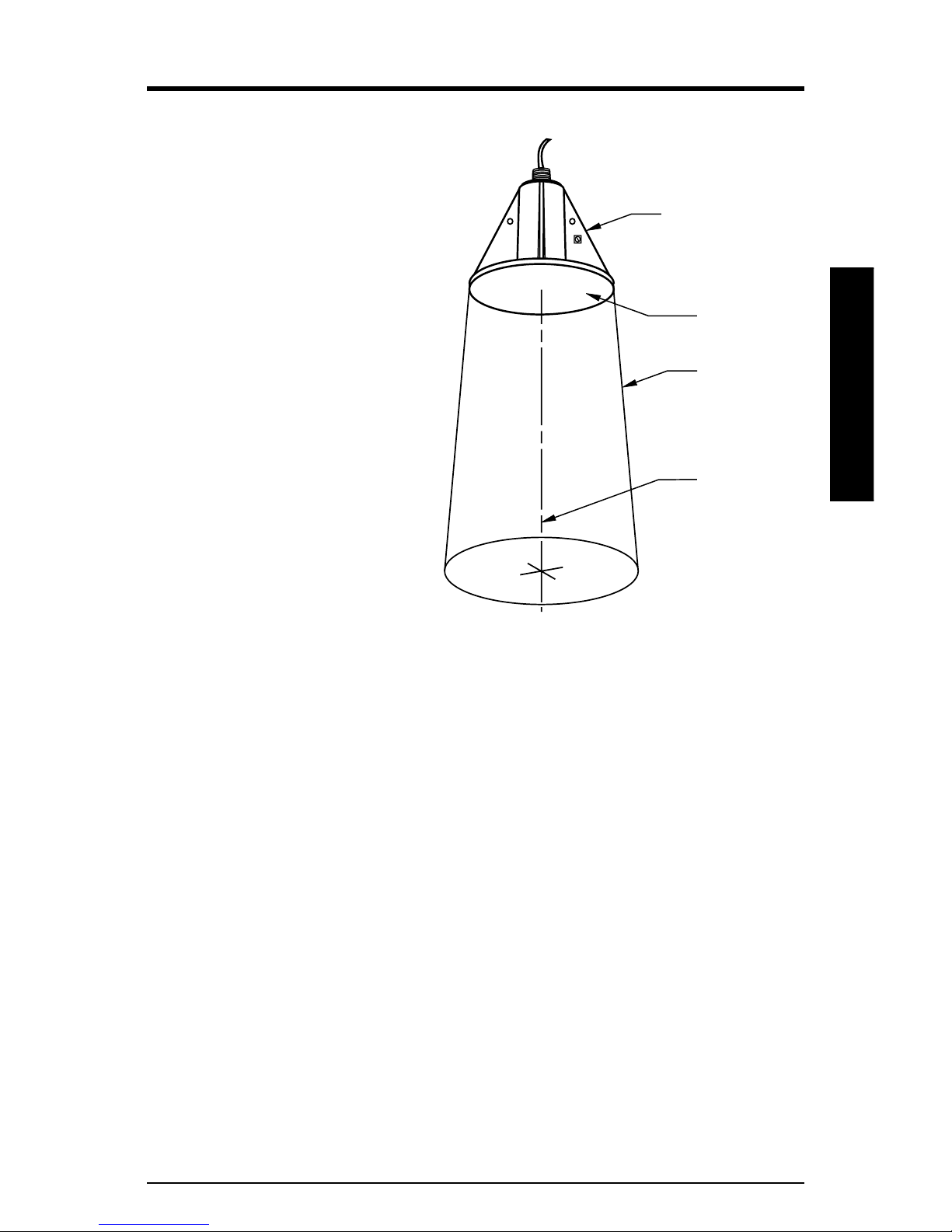
About the Transducer
The Echomax XLS / XLT series of
transducers operates in
association with Milltronics
ultrasonic level monitoring
products.
The transducer converts the
electrical energy of the transmit
pulse from the transceiver into
acoustical energy. It then
converts the acoustical energy
of the echo back into electrical
energy for the transceiver
receive period.
The effective acoustical
energy is emitted from the
transducer face and radiated
outward, decreasing in
amplitude at a rate inversely
proportional to the square of
the distance. Maximum
power is radiated axially
(perpendicular) from the
transducer face in a line referred to as the axis of transmission. Where
power is reduced by half ( – 3 dB), a conical boundary def ining the sound
beam, centered about the axis of transmission, is established. The diametric
measurement of the cone in degrees defines the beam angle. Impedance
matching techniques are used to optimize the transfer of pow er from the
transducer into air and vice versa.
transducer
transducer
face
-3db
boundary
axis of
transmission,
perpendicular
to transducer
face
About the Transducer
The XLS / XLT transducers incorporate an integral temperature sensor that
reports the air temperature at the transducer to the transceiver. The
connection is transparent, in that both the ultrasonic and temperature
components of the transducer use the same wires.
PL-522 XLS/XLT Series Transducers Page 7
Page 8

General Guidelines
The equipment may be used in all hazardous areas with all gases with
temperature classes T1, T2, T3, T4, and T5 for the XLS-30 and XLS-6 0, and
T1, T2, and T3 for the XLT-30 and XLT-60. The XLS series is only certified
for use in ambient temperatures in the range of -40°C to 90°C and the XLT
series is only certified for use in an ambient range of -40°C to 150°C. Neither
should be used outside their respective temperature ranges.
• Installation shall be carried out in accordance with the applicable code of
practice, and by suitably trained personnel.
• These devices should only be supplied from a circuit containing a suitablyrated fuse that has a breaking capacity of 4000A. This fuse is included in
Milltronics’ transceivers.
• Repair of this equipment shall be carried out in accordance with the
applicable code of practice.
About the Transducer
• The certification of the XLS and XLT range of transducers rely upon the
following materials used in its construction:
Enclosure: Aluminum
Encapsulant: Durapot 861-F3 / 864
• Manual override can be accomplished by using the disconnect switch
provided in the building installation of the associated controller.
Page 8 XLS/XLT Series Transducers PL-522
Page 9

Outline and Dimensions
safety connection
9 mm (3/8") dia.
hole (2 places)
1” NPT
earth connection
screw clamp
(1 place)
h
(nominal)
Outline & Dimensions
d
XLS / XLT - 30 XLS / XLT - 60
h 249 mm (9.8") 324 mm (12.75")
d 264 mm (10.4") 335 mm (13.2")
PL-522 XLS/XLT Series Transducers Page 9
Page 10

Outline & Dimensions
Page 10 XLS/XLT Series Transducers PL-522
Page 11

Mounting
Recommendations
• Mount the transducer so that it is above the maximu m material level by at
least the blanking value. Refer to the associated transceiver manual.
• On liquid applications, the transducer must be mounted so that the axis of
transmission is perpendicular to the liquid surface.
• On solids applications, a Milltronics Easy Aimer should be used to facilitate
aiming of the transducer.
• Secure installation by connecting a safety chain from the transducer to a
structural member.
• Consider the optional temperature sensor when mounting the transducer.
Notes:
• Wear proper ear protection in the vicinity of the operating transducer.
The XLS/XLT 60 transducers could emit hazardous sound
pressure. They sha ll be installed in such a manner that the
sound pressure will be reduced to a non-hazardous level.
Solids Applications
Easy Aimer
(typical model)
to nearest earth
Mounting
PL-522 XLS/XLT Series Transducers Page 11
safety chain
earth connection
Page 12

Liquid Applications
Flexible Conduit
flexible conduit
coupling
safety chain
transducer
Blind Flange
nipple welded to blind flange
coupling
to nearest earth
to nearest earth
Mounting
safety chain
Flange, gasket and hardware supplied by customer.
Refer to Standpipes on page 16.
Page 12 XLS/XLT Series Transducers PL-522
coupling
Page 13

Interconnection
Direct Connection
blk
wht
Milltronics transceiver
(typical)
blk/hot
wht/shld
2 Wire Extension
Coaxial Extension
blk
wht
junction
box
drain/shield
extend cable using 18 AWG
shielded / twisted pair
Note:
Grounding transducer as shown is mandatory per safety regulations,
and for isolation against elec tr ical interference.
PL-522 XLS/XLT Series Transducers Page 13
extend cable using RG – 62 A/U
coax for optimum signal to noise ratio
Interconnection
Page 14

Recommendations
Note:
Installation shall only be performed by qualified personnel and in
accordance with local gove rning regulations.
For best results follow these installation rules:
• Do not route cable openly, instead run cable separately in a grounded metal
conduit to p rotect it from ambient electrical noise.
• Seal all thread connections to prevent the ingress of moisture.
• Do not run cable near high voltage or current runs, contactors or SCR
control drives.
Interconnection
Page 14 XLS/XLT Series Transducers PL-522
Page 15

Applications
Notes:
• The transducer is to be used only in the manner outlined in this
instruction manual.
• This transducer requires no maintenance, and is recommended for use
with liquids only.
Solids
Applications
1
bin wall seams
2
filling profile
emptying profile
1. Transducer angled to avoid wall seams, and
aimed at discharge in order to read empty bin.
2. Avoid intersecting bin wall seams, structural
members an d wall irregularities. Otherwise,
refer to transceiver manual
Easy Aimer
3
3. Transducer too close to materi al inlet.
Falling material will intersect sound beam
and cause erroneous readings or loss of
echo.
4
4. On fluid-like sol ids, aim transducer
perpendic ular to material s urface
PL-522 XLS/XLT Series Transducers Page 15
transducer
5
minimal angle
of repose
discharge
5. On dual discharge bins, aim each
transduc er at the discharge point.
Page 16

Liquids
Standpipes
In many applications, access must be made via a standpipe. In such cases
the transducer is hung from a blind flange.
Applications
The standpipe length should be as short and the diameter as large as
possible. As a rule of thumb, the -3 dB cone of the sound beam should not
intersect the standpipe wall in applications opening into a vessel or larger
area. Otherwise, additional blanking will be required to compensate for the
interference zone created by the opening.
nipple welded
into blind flange
transducer
no
intersection
no additional blanking required.no additional blanking required.
sound beam
intersects
no additional blanking required.
reflection at
interference
zone created
by opening
near blanking extension of 150 mm (6") past end of
standpipe may be required.
Page 16 XLS/XLT Series Transducers PL-522
Page 17

Volume
Maintain full
fluid level for
full or offset
calibration.
Do not allow
material to
enter blanking
zone.
‘B’
‘A’
‘C’
Applications
2
3
span:
corresponds to
beam
angle
tank
manufacturer’s
empty level
Empty level for ‘B’
location. Below this
level, echo would
reflect away from
the transducer.
rise
run
1
discharge
4
tank
manufacturer’s
empty level
A. Primary location. This is the preferred location and should be used
whenever possible. The centre of the tank generally gives the most reliable
readings because there are fewer obstructions to provide false echos.
B. Alternate location. This location is used if the centre of the tank is already
in use or if the tank roof is too weak to hold the transducer safely.
C. Poor location. This is a poor installation location. The echos are shown
reflecting away from the transducer face.
PL-522 XLS/XLT Series Transducers Page 17
Page 18

Notes
1. Beam should not detect bin bottom.
If this occurs, use range extension parameters (on transceivers where
available) to omit false echoes. A 5° beam angle represents a rise:run ratio
of approximately 20:1. In most tanks the transducer should be centred as
Applications
much as possible (without interference from inlet) for optimum reading
range.
2. Sound beam must be perpendicular to liquid surface.
When mounting the standpipe and flange you must ensure that the
transducer face will be parallel with the liquid’s surface.
3.
Echo has missed an improperly levelled transducer.
As in 2, ensure that the standpipe and flange are mounted to set the
transducer face level with the measured liquid.
4.
Calibrate under normal conditions.
When performing an empty or full calibration, the tank must contain its
normal vapour and be at its normal temperature.
Maintenance
This transducer requires no maintenance, but if performance changes are
observed, shut down the system and promptly inspect the complete system
including the transducer.
Page 18 XLS/XLT Series Transducers PL-522
Page 19

Installation Diagrams
Connection Diagram
Installation Diagrams
PL-522 XLS/XLT Series Transducers Page 19
Page 20

Interconnection Diagram
Installation Diagrams
Page 20 XLS/XLT Series Transducers PL-522
Page 21

*7ml19981al01*
 Loading...