

Page 1
EXTERNAL MODEM KIT
Instruction Manual
October 2002
Page 2

Safety Guidelines
Warning notices must be observed to ensure personal safety as well as that of others, and to
protect the product and the connected equipment. These warning notices are accompanied
by a clarification of the level of caution to be observed.
Qualified Personne l
This device/system may only be set up and operated in conjunction with this manual.
Qualified personnel are only authorized to install and operate this equipment in accordance
with established safety practices and standards.
Warning: This product can only function properly and safely if it is correctly transported,
stored, installed, set up, operated, and maintained.
Note: Always use product in accordance with specifications.
Copyright Siemens Milltronics Process
Disclaimer of Liability
Instruments Inc. 2002. All Rights Reserved
This document is available in bound version and in
electronic version. We encourage users to
purchase authorized bound manuals, or to view
electronic versions as designed and authored by
Siemens Milltronics Process Instruments Inc.
Siemens Milltronics Process Instruments Inc. will
not be responsible for the contents of partial or
whole reproductions of either bound or electronic
versions.
MILLTRONICS®is a registered trademark of Siemens Milltronics Process Instruments Inc.
Contact SMPI Tech nical Publications at the follo win g address:
Technical Publications
Siemens Milltronics Process Instruments Inc.
1954 Technology Drive, P.O. Box 4225
Peterborough, Ontario, Canada, K9J 7B1
Email: techpubs@siemens-milltronics.com
While we have verified the contents of
this manual for agreement with the
instrumentation described, variations
remain possible. Thus we cannot
guarantee full agreement. The
contents of this manual are regularly
reviewed and corrections are included
in subsequent editions. We welcome
all suggestions for improvement.
Technical data subject to change.
For the library of SMPI instruction manuals, visit our Web site: www.siemens-milltronics.com
© Siemens Milltronics Process Instruments Inc. 2002
Page 3

Table of Contents
Specifications...................................................................................................................... 1
RS-232 Modem Kit................................................................................................................................... 1
RS-485 Modem Kit................................................................................................................................... 1
Warranty............................................................................................................................... 1
The External Modem Kit.................................................................................................... 2
Components.............................................................................................................................................. 2
Dimensions .......................................................................................................................... 3
RS-232 Modem ...............................................................................................................................3
RS-485 Modem ...............................................................................................................................3
Power Supply .................................................................................................................................4
Assembly Instructions....................................................................................................... 5
Configuring External Modem........................................................................................... 6
Configuring Instrument...................................................................................................... 9
RS-232 Modem Kit Instruments........................................................................................................... 9
EnviroRanger ERS 500 ..................................................................................................................9
Accumass BW500/SF500: .........................................................................................................10
AiRanger with SmartLinx®Modbus RTU card ....................................................................11
Open Channel Meter OCM III ...................................................................................................12
RS-232 Modem to PC Connection..................................................................................................... 12
RS-485 Modem Kit Instruments......................................................................................................... 13
Modem Dip Switch Settings .....................................................................................................13
MultiRanger 100/200, HydroRanger 200 ................................................................................13
IQ Radar 300 .................................................................................................................................14
AiRanger with SmartLinx®Modbus RTU Card (for multidrop applications) ................14
EnviroRanger ERS 500 ................................................................................................................15
Configuring Internal Modem.......................................................................................... 17
Communicating using Modbus ................................................................................................17
Communicating using Flow Reporter .....................................................................................18
7ML19981DP02 External Modem Kit – INSTRUCTION MANUAL Page i
Page 4

Page ii External Modem Kit – INSTRUCTION MANUAL 7ML19981DP02
Page 5

Specifications
RS-232 Modem Kit
Modem:
• VT-Modem-1 WW, SIXNET external modem, DIN rail or flat panel mountable
• refer to SIXNET modem manual and CD
Power Supply:
• Siemens 120 V AC/230V AC input, 24V/1.3A output, DIN rail or flat panel mountable
• refer to Siemens power supply manual
Compatible Instruments:
• EnviroRanger ERS 500, Accumass BW500/SF500, AiRanger with SmartLinx®
Modbus RTU card, OCM III Open Channel Meter
Note: The RS-232 Modem Kit can be used as a modem connected to the PC as well.
RS-485 Modem Kit
Modem:
• VT-Modem-3 WW, SIXNET external modem, DIN rail or flat panel mountable
• refer to SIXNET modem manual and CD
Power Supply:
• Siemens 120 V AC/230V AC input, 24V/1.3A output, DIN rail or flat panel mountable
• refer to Siemens power supply manual
Compatible Instruments:
• MultiRanger 100, MultiRanger 200, HydroRanger 200, IQ Radar 300, AiRanger with
Smartlinx®Modbus RTU card (for multi-drop applications), EnviroRanger ERS 500
with option card (for multi-drop applications)
Warranty
All components of the external modem kit are covered by their individual manufacturer’s
warranties. Siemens Milltronics Process Instruments Inc. does not provide warranty on
any of the modem kit components, separately or together.
7ML19981DP02 External Modem Kit – INSTRUCTION MANUAL Page 1
Page 6

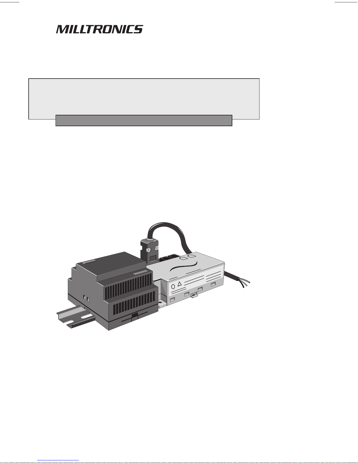
The External Modem Kit
The External Modem Kit is assembled to assist users connecting external modems to
Milltronics brand products. While any modem can work with Siemens Milltronics brand
products, the VT-Modem by SIXNET is easy to use and reliable. For best results, use the
RS-232 Modem Kit for the PC side and RS-232 and RS-485 Modem kit for device side.
When connecting to the OCM III, Siemens Milltronics recommends using Flow Reporter
software. When working with Modbus RTU, we recommend the Modbus Serial driver by
Kepware (www.kepware.com).
Components
RS-232 Modem Kit RS-485 Modem Kit
SIXNET VT-Modem-1 WW Modem SIXNET VT-Modem-3 WW Modem
modem programming cable (DB-9) modem programming cable (DB-9)
Siemens power supply, 24V/1.3A Siemens power supply, 24V/1.3A
2-wire power transfer cable 2-wire power transfer cable
3-wire custom communication cable RS-485 cable (3 ft)
Page 2 External Modem Kit – INSTRUCTION MANUAL 7ML19981DP02
Page 7
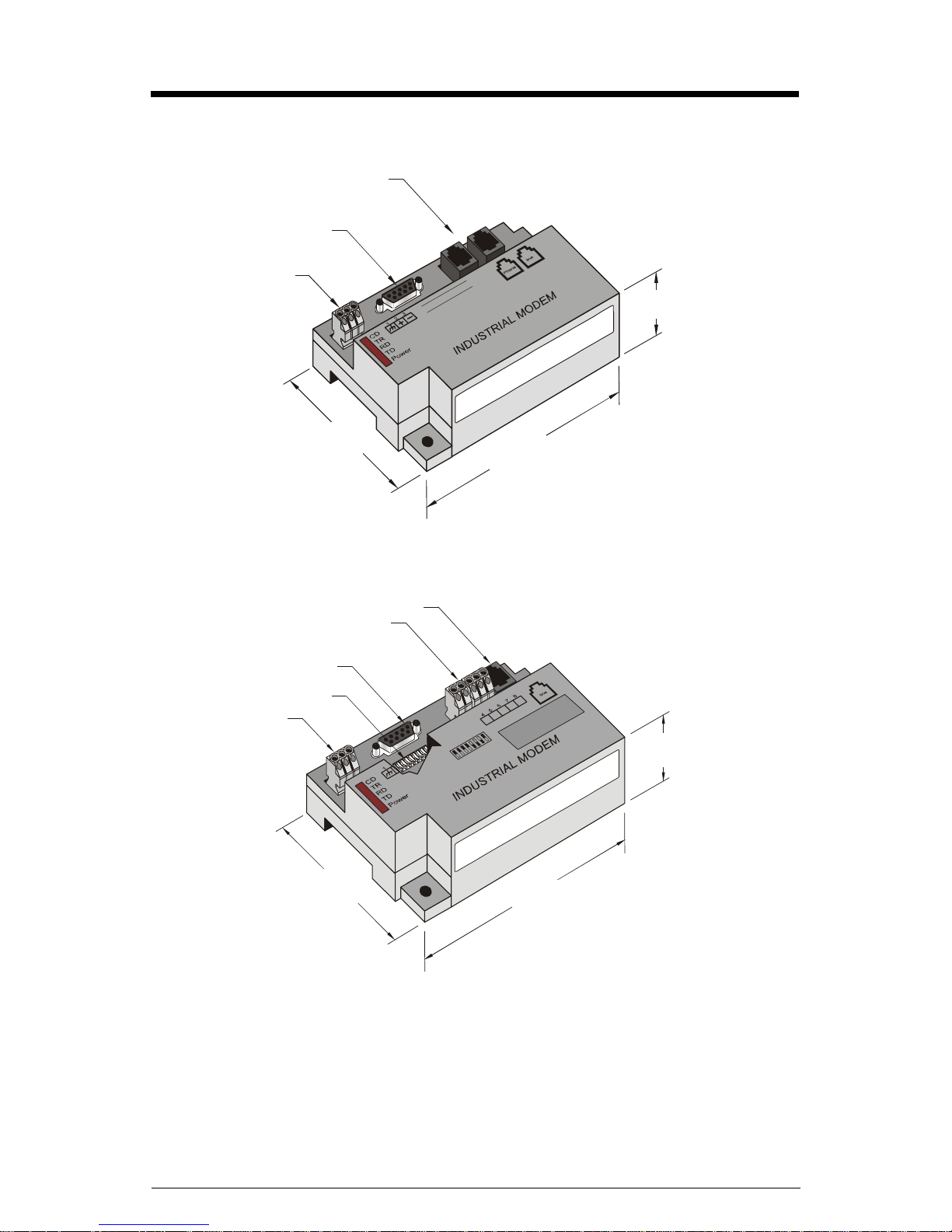
Dimensions
RS-232 Modem
RJ-11 jack
DB-9
connector
power terminal
block
74.2mm
(2.92")
80.5mm
(3.11")
120.7mm
(2.92")
RS-485 Modem
RS-485 terminal block
DB-9 connector
dip switches
power terminal
block
74.2 mm
(2.92")
RJ-11 jack
80.5 mm
(3.11")
120.7 mm
(4.75")
7ML19981DP02 External Modem Kit – INSTRUCTION MANUAL Page 3
Page 8
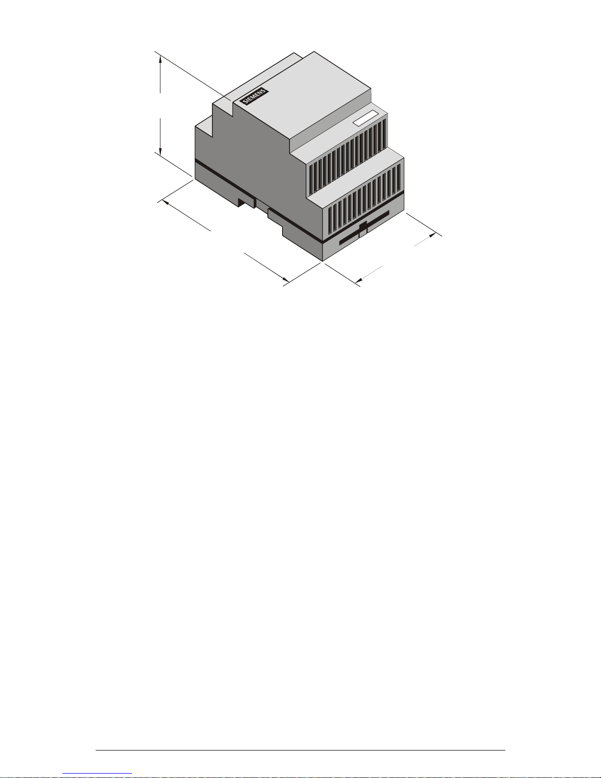
Power Supply
57.2mm
(2.25")
88.9mm
(3.50")
69.8mm
(2.75")
Page 4 External Modem Kit – INSTRUCTION MANUAL 7ML19981DP02
Page 9

Assembly Instructions
Note: Customer supplied required parts and tools:
• power cable
• cabinet ground wire
•ohmmeter
• RJ-11 phone cord
1. Turn off the main AC power supply. Connect the AC power cable to the AC power
connection on the power supply marked as N and L1.
2. Connect the power transfer cable to the power supply and modem as follows:
• +V on power supply to terminal 2 (+) on modem using clear wire.
• –V on power supply to terminal 3 (-) on modem using black wire.
Connect the ground on the modem to the cabinet ground (wire not provided).
3. Turn on power to the power supply. Connect modem programming cable to modem’s
DB-9 connector and then to an available port on a PC (eg. Com 1).
4. Configure external modem. See detailed instructions on page 6.
Disconnect the programming cable when finished.
5. Connect the Siemens Milltronics product to the external modem using the
appropriate wiring code (see Configuring Instruments on page 9).
6. Program the Siemens Milltronics product using the correct parameters listed in
Configuring Instruments section. Connect external modem to analog phone line
using RJ-11 telephone cable in the modem’s line jack.
7. Configure the internal modem in laptop or desktop PC using Windows 95 or 98 to
communicate using Modbus RTU protocol. (See Configuring Internal Modem on
page 17.)
8. Dial in to Siemens Milltronics product using internal modem.
Note: When modem and power supply are mounted in an external enclosure,
ensure they are not exposed to the elements, dust, or debris.
Communications Cable
-
321
N
--
+++
L1
7ML19981DP02 External Modem Kit – INSTRUCTION MANUAL Page 5
Black Clear
Power connection
Page 10

Configuring External Modem
Install SIXNET Modem Setup Wizard from SIXNET CD. After installation, run the SIXNET
Setup Wizard. When configuring the VT-Modem-1, choose default options after changing
country of installation (See Step 2).
1*
2
3
1. Open configuration file and choose the file for your application.
File Name Associated Product
SMPI_modbus232.6ms EnviroRanger ERS 500, Accumass BW500, Accumass
SF500, AiRanger with Smartlinx Modbus RTU Card
SMPI_OCM.6ms OCM III
SMPI_modbus485.6ms MultiRanger 100 / 200, HydroRanger 200,
IQ Radar 300, AiRanger with Smartlinx Modbus RTU Card
(multi-drop applications)
SMPI_ocm_master.6ms PC connecting to OCM III (via FlowReporter)
SMPI_modbus_master.6ms PC connecting to Siemens Milltronics Modbus devices
Notes
• If the files listed above are not on the SIXNET CD, they can be found on the
Siemens Milltronics web site at www.siemens-milltronics.com
• The SIXNET Modem Setup Wizard screens will differ slightly according to the
configuration file shown. The example shown is for Modbus RS-232
communication.
2. Choose country from drop-down list if installation is outside North America.
3. Click Next.
Page 6 External Modem Kit – INSTRUCTION MANUAL 7ML19981DP02
Page 11

4. Choose the COM port for your computer.
5. Click Next.
4
5
6. Click Next.
7ML19981DP02 External Modem Kit – INSTRUCTION MANUAL Page 7
6
Page 12

7
8
9
7. Save Configuration file.
8. After connecting the modem programming cable to modem’s DB-9 connector and
the designated port on your PC, and setting the dip switches (RS-485 modem only),
write configuration file to the modem.
9. Click Finish.
The external modem is now configured for 9600 baud communication.
For communication from the PC, use either the RS-232 Modem Kit (see page 12 for PC
connection) or use an internal PC modem.
The internal modem (Modbus Master) must be set up for:
•Modbus RTU
•8 data bits
•1 stop bit
• no parity
• no flow control
(See Configuring Internal Modem on page 17)
Page 8 External Modem Kit – INSTRUCTION MANUAL 7ML19981DP02
Page 13

Configuring Instrument
RS-232 Modem Kit Instruments
EnviroRanger ERS 500, Accumass BW500, Accumass SF500,
AiRanger with SmartLinx® Modbus RTU card, OCM III
EnviroRanger ERS 500
Port 2 set-up parameters:
Parameter Description
P770 (2)* = 3 Modbus RTU slave
P771 (2) = 1 Modbus slave address of 1
P772 (2) = 9.6 9600 baud
P773 (2) = 0 no parity
P774 (2) = 8 8 data bits
P775 (2) = 1 1 stop bit
P776 (2) = 0 no flow control
P777 (2) = 0 no key up delay
P778 (2) = 1 answer only
P779 (2) = 300 Modem inactivity timeout = 300
*(2) refers to the primary index (secondary index 0).
Wiring Diagram for Connection to EnviroRanger ERS 500 (Rack and P anel Mount)
1. Use an ohmmeter to rung out the communication cable. Determine which pin
connects with each wire of the cable.
2. Connect the communication cable to the ERS 500 as follows:
ERS 500
TERMINAL
BLOCK
RXD RXD
38
TXD TXD
39
40
GND GND
41
62153487
DB-9
CONNECTOR
7ML19981DP02 External Modem Kit – INSTRUCTION MANUAL Page 9
Page 14

Wiring Diagram for Connection to EnviroRanger ERS 500 (Wall Mount):
R
ERS 500
TERMINAL
BLOCK
RXD RXD
19
TXD TXD
20
21
GND GND
22
62153487
DB-9
CONNECTO
Accumass BW500/SF500:
Port 1 set-up parameters:
Parameter Description
P770 (1)* = 3 Modbus RTU slave
P771 (1) = 1 Modbus slave address of 1
P772 (1) = 2 9600 baud
P773 (1) = 0 no parity
P774 (1) = 8 8 data bits
P775 (1) = 1 1 stop bit
P778 (1) = 1 modem attached
P779 (1) = 300 Modem inactivity timeout = 300
*(1) refers to the primary index (secondary index 0)
Note: After setting Port 1 parameters for the BW500 and SF500, you must cycle
power to the unit for them to take effect.
Page 10 External Modem Kit – INSTRUCTION MANUAL 7ML19981DP02
Page 15

Wiring Diagram for Connection to Accumass BW500/SF500:
1. Use an ohmmeter to rung out the communication cable. Determine which pin
connects with each wire of the cable.
2. Connect the communication cable to the BW500/SF500 as follows
BW 500
TERMINAL
BLOCK
TX
31
COM
32
RX
33
34
TX
COM
RX
CONNECTOR
AiRanger with SmartLinx®Modbus RTU card
Port 1 set-up parameters:
Parameter Description
P751 = 3 9600 baud
P752 = 0 no parity
P753 = 1 station address 1
P758 = 15 interframe spacing = 15 ms
62153487
DB-9
Wiring Diagram for Connection to AiRanger with SmartLinx® Modbus RTU card
1. Use an ohmmeter to rung out the communication cable. Determine which pin
connects with each wire of the cable.
2. Connect the communication cable to the AiRanger as follows:
AIRANGER WITH
SMARTLINX MODBUS
TM
RTU CARD
1
2
3
4
RX RX
TX TX
GND
GND
CONNECTOR
62153487
DB-9
7ML19981DP02 External Modem Kit – INSTRUCTION MANUAL Page 11
Page 16

Open Channel Meter OCM III
OCM III Configuration Parameters
Parameter Description
P37 = 5 9600 baud
Wiring Diagram for connection to OCM III:
OCM III
TERMINAL
BLOCK
TXD
11
RXD
12
GND SG
13
*
1
2
345
89
67
Jumper Pins
RXD
TXD
62153487
DB-9
CONNECTOR
*Note: Jumpers are required for communication with the OCM III. The jumpers are
included in communications cable supplied with Siemens Milltronics RS-232 External
Modem Kit.
To configure the OCM III and Flow Reporter software for modem communication, you
must use an external modem kit or configure your internal modem using settings for Flow
Reporter. See page 18 for more information.
RS-232 Modem to PC Connection
Connect the PC to the modem using the modem programming cable.
To configure your RS-232 Modem and PC:
1. Connect the modem to PC serial port 1 or 2.
2. On the Start Menu, click SETTINGS and click CONTROL PANEL.
3. Double-click MODEMS.
4. Click Add Modem.
5. Check "Don’t detect my modem: I will select it form a list" and click NEXT.
6. Select Manufacturers: (Standard Modem) and then select Modem: Standard 9600
bps Modem.
7. Select all the defaults until modem is installed.
Page 12 External Modem Kit – INSTRUCTION MANUAL 7ML19981DP02
Page 17

RS-485 Modem Kit Instruments
MultiRanger 100, MultiRanger 200, HydroRanger 200, IQ Radar 300,
AiRanger with Smartlinx Modbus RTU Card (multidrop applications)
Modem Dip Switch Settings
Set the Modem dip switches as follows:
1 2345678
MultiRanger 100/200, HydroRanger 20 0
Port 2 set-up parameters:
Parameter Description
P770 (2)* = 3 Modbus RTU slave
P771 (2) = 1 Modbus slave address of 1
P772 (2) = 9.6 9600 baud
P773 (2) = 0 no parity
P774 (2) = 8 8 data bits
P775 (2) = 1 1 stop bit
P778 (2) = 1 modem attached
P779 (2) = 300 Modem inactivity timeout = 300
on
off
*(2) refers to the primary index (secondary index 0).
Wiring Diagram for Connection to MultiRanger 100/200, HydroRanger 200
1. Connect the communication cable to the MultiRanger 100/200 or HydroRanger 200
as follows:
MultiRanger 100/200,
HydroRanger 200
Terminal Block
COM GND
34
A- TD
35
36
B
+ TD
4
RS-485 Modem
Terminal Block
6
5
7ML19981DP02 External Modem Kit – INSTRUCTION MANUAL Page 13
Page 18

IQ Radar 300
k
Port 2 set-up parameters:
Parameter Description
P770 = 3 Modbus RTU slave
P771 = 1 Modbus slave address of 1
P772 = 9.6 9600 baud
P773 = 0 no parity
P774 = 8 8 data bits
Wiring Diagram for Connection to IQ Radar 300
1. Connect the communication cable to the IQ Radar 300 as follows:
IQ Radar 300
Terminal Block
3
B
4
COM
5
TD -
TD +
GND
4
5
RS-485 Modem
Termi nal Bloc
6
AiRanger with SmartLinx®Modbus RTU Card (for
multidrop applications)
SmartLinx Modbus RTU Card port configuration (for RS-485 transmission):
ON
AiRanger Port 1 set-up parameters:
Parameter Description
P751 = 3 9600 baud
P752 = 0 no parity
P753 = 1 station address 1
P758 = 15 interframe spacing = 15 ms
Page 14 External Modem Kit – INSTRUCTION MANUAL 7ML19981DP02
18
Page 19

Wiring Diagram for Connection to AiRanger with SmartLinx® Modbus RTU card
1. Connect the communication cable to the AiRanger as follows:
AIRANGER WITH
SMARTLINX MODBUS RTU CARD
(MULTI-DROP APPLICATIONS)
TM
GND
3
ATD -
4
B
5
6
EnviroRanger ERS 500
Port 3 set-up parameters:
Parameter Description
P770 (3) = 3* Modbus RTU slave
P771 (3) = 1 Modbus slave address of 1
P772 (3) = 9.6 9600 baud
P773 (3) = 0 no parity
P774 (3) = 8 8 data bits
P775 (3) = 1 1 stop bit
P776 (3) = 0 no flow control
P777 (3) = 0 no key-up delay
P778 (3) = 1 modem attached
P779 (3) = 300 modem inactivity timeout = 300
GND
TD +
4
5
RS-485 MODEM
TERMINAL BLOCK
6
*(3) refers to the primary index (secondary index 0).
7ML19981DP02 External Modem Kit – INSTRUCTION MANUAL Page 15
Page 20

Wiring Diagram for Connection to EnviroRanger ERS 500
Connect the communication cable to the EnviroRanger ERS 500 Wall Mount as follows:
Enviroranger ERS 500
(Wall Mount)
Term i n a l Bl o ck
B
101
ATD -
102
COM GND
103
TD +
5
4
RS-485 Modem
Ter mi n a l St r i p
6
Connect the communication cable to the EnviroRanger ERS 500 Rack and Panel Mount as
follows:
Enviroranger ERS 500
(Rack Mount)
Ter mina l B l o ck
B
49
ATD -
50
COM GND
51
TD +
5
4
RS-485 Modem
Terminal Strip
6
Page 16 External Modem Kit – INSTRUCTION MANUAL 7ML19981DP02
Page 21

Configuring Internal Modem
Communicating using Modbus
The internal modem communicating with the external modem and Siemens Milltronics
instrument must communicate using the Modbus RTU serial protocol.
Setting up internal modem using Windows:
1. On the Start Menu, click SETTINGS and click CONTROL PANEL.
2. Double-click MODEMS.
3. Highlight the internal modem being used and then click PROPERTIES.
4. Select the GENERAL tab. Set speed to 9600 using Maximum Speed dropdown menu.
5. Select the CONNECTION tab. Under Connection Preferences, set data bits to 8,
parity to NONE, stop bits to 1.
6. Click ADVANCED at bottom right of Connection screen.
7. Verify the Use error control and Use flow control boxes are not checked.
8. Verify Modulation type is Standard.
9. Save changes and exit.
10. Reboot computer.
Modem configuration:
•Modbus RTU
•9600 baud
•8 data bits
•1 stop bit
• no parity
• no flow control
7ML19981DP02 External Modem Kit – INSTRUCTION MANUAL Page 17
Page 22

Communicating using Flow Reporter
Configuring Flow Reporter:
– Select Port from the Flow Reporter main menu and select Modem.
– In the Modem Port box, select your modem’s COM port.
Configuring the internal PC modem when using Flow Reporter software and
OCM III:
1. On the Start Menu, click SETTINGS and click CONTROL PANEL.
2. Double-click MODEMS.
3. Highlight the internal modem being used and then click PROPERTIES.
4. Select the GENERAL tab. Set speed to 9600 using Maximum Speed dropdown menu.
5. Select the CONNECTION tab. Under Connection Preferences, set data bits to 8,
parity to NONE, stop bits to 1.
6. Click ADVANCED at bottom right of Connection screen.
7. Verify the Use error control box is not checked
8. Verify that the Use flow control box is checked and that XON/XOFF is selected.
9. Verify Modulation type is Standard.
10. Reselect the CONNECTION tab. Choose PORT settings and verify that the Use FIFO
buffers box is checked.
11. Save changes and exit.
12. Reboot computer.
Page 18 External Modem Kit – INSTRUCTION MANUAL 7ML19981DP02
Page 23

Page 24

2
Rev. 2.1
*7ml19981dp02*
 Loading...