

Page 1

Instruction Manual
PL-590
XRS-5 Transducer
Page 2
t Milltronics, we endeavour
Ultrasonic level
Capacitance
Radar
Point level
A
to design equipment that is
simple to use and reliable in its
operation, with the aim of
satisfying our customers' needs.
Milltronics has been designing
and manufacturing electronics
based process measurement
equipment since 1954. Our
fields of expertise include
continuous and point level
measurement, weighing and
feeding systems and motion
sensing.Technologies include
ultrasonic, capacitance and
microwave radar.
Communications
Weigh feeders
Motion sensing
Belt scales
Flowmeters
Acoustic sensing
Milltronics sells and markets
world wide through
subsidiaries, distributors and
representatives. Through
continuous improvement, we
are striving to provide our
customers with first rate sales
information, engineering
assistance and after sales
support.
For more details on our
products and services, please
contact us and we will provide
you with a listing of the offices
or representatives nearest you.
Page 3

Table of Contents
Specifications
About the Transducer ..................................................................................7
General Guidelines .................................................................................8
Installation.....................................................................................................9
Outline and Dimensions ..........................................................................9
Mounting .....................................................................................................11
Recommendations ................................................................................ 11
Applications................................................................................................ 13
Open Channel Meter............................................................................. 13
Standpipes and Stilling Wells................................................................14
Water / Wastewater............................................................................... 15
Transducer Placement ..........................................................................16
Locations............................................................................................... 16
Interconnection
Direct Connection.................................................................................. 19
Coaxial Connection ...............................................................................20
2-Wire Extension (for EnviroRanger ERS 500 only) .............................20
Maintenance
..............................................................................................5
..........................................................................................19
...............................................................................................20
Installation Diagram ...................................................................................21
PL-590 XRS-5 Transducer Page 3
Page 4

Page 4 XRS-5 Transducer PL-590
Page 5

Specifications
Specifications
Process Application:
{
Measurement Range{0.3 to 5m (1 to 15 ft) typical
{
Vessel Pressure
Operation:
{
Beam Angle
{
Frequency
{
Temperature Sensor
{
Supply Source
Environmental
{
Location
{
Ambient temperatures{-20 to 65 °C (-4 to 149 °F)
{
Altitude
{
Pollution degree
:
Construction:
{
Housing
{
Mounting
{
liquids and slurries
(may depend on application variables)
{
vented to atmosphere
{
10°
{
43 KHz
{
internal
{
transducer shall only be supplied by Milltronics
certified controller
{
indoor / outdoor
{
2000 m maximum
{
4
2
{
Kynar Flex®1 body and Hypalon
{
1” NPT conduit connection
face
Cable:
{
2 wire shielded / twisted, 0.5 mm2 (18 AWG) PVC jacket
Ingress protection:
{
IP-68
Weight
Options
3
:
{
1.2 Kg (2.6 lb)
:
{
factory flanged to suit ANSI , DIN or JIS standard
{
split flange (field mount) to suit ANSI, DIN or JIS standard
{
submergence shield (flooding applications)
Cabling (maximum run):
{
365 m (1200 ft) using RG-62 A/U coaxial cable
{
365 m (1200 ft) using 2-wire twisted pair / braided and foil shielded 20
AWG (0.5 mm
Approvals
{
CE4, CSA, FM, CENELEC, ATEX, see device nameplate
:
2
), PVC jacket (EnviroRanger ERS 500 only)
1
Kynar Flex® is registered trade mark of ELF Atochem.
2
Hypalon® is a registered trademark of Du Pont
3
approximate weight of transducer with standard cable length
4
EMC performance available upon request
PL-590 XRS-5 Transducer Page 5
Page 6

Specifications
Page 6 XRS-5 Transducer PL-590
Page 7
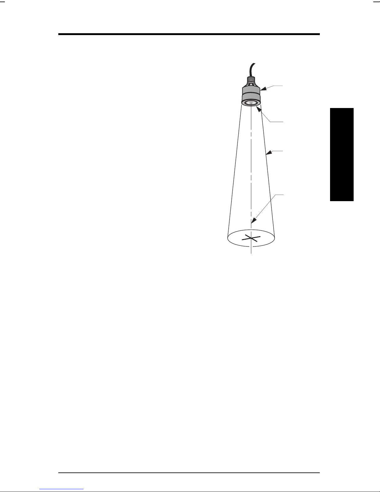
About the Transducer
The Echomax XRS-5 transducer works with Milltronics transceivers and
provides the ultrasonic pulse and echo reception
that these devices require.
The transducer converts electrical pulses
provided by the transceiver to ultrasonic pulses
used for measurement and then converts the
ultrasonic echoes back to an electrical signal.
This signal is interpreted by the Milltronics
tranceiver using the patented Sonic
Intelligence™ algorithms. The ultrasonic pulse
reduces in power by 3dB in a 10° cone from the
transducer face. It is important to keep objects
out of this cone to reduce the chance of false
echos being recorded.
The XRS-5 transducer incorporates an
integral temperature sensor that reports the
ambient temperature to the transceiver. The
connection is transparent in that both the
ultrasonic and temperature components of
the transducer use the same leads. This
ensures that the Milltronics transceiver can
automatically compensate the speed of
sound constant for varying temperatures.
transducer
transducer
face
-3db
boundary
axis of
transmission,
perpendicular
to transducer
face
About this …
PL-590 XRS-5 Transducer Page 7
Page 8

General Guidelines
The equipment may be used in all hazardous zones with all gases with
temperature classes T1, T2, T3, T4, T5 and T6. The equipment is only
certified for use in ambient temperatures in the range of -20°C to +65°C and
should not be used outside this range.
• Installation shall be carried out in accordance with the applicable code of
practice by suitably trained personnel.
• The apparatus shall only be supplied from a circuit containing a suitably-
rated fuse having a breaking capacity of 4000A. This fuse is included in
Milltronics’ transceivers.
• Repair of this equipment shall be carried out in accordance with the
applicable code of practice.
• The certification of this equipment relies on the following materials used in its
About this …
construction:
Enclosure: Kynar Flex 2800-02 (former designation 2820) /
Chlorosulfonated polyethylene / Nitrile / Ethylene propylene
/ Chloroprene
Encapsulant: LA-9823-76
• Manual override can be accomplished by using the disconnect switch
provided in the building installation of the associated controller.
Page 8 XRS-5 Transducer PL-590
Page 9

Installation
Outline and Dimensions
Standard Flange (optional)
127mm
(5.0”)
89mm
(3.5”)
ANSI, DIN or JIS
standards
Submergence Shield Split Flange (optional)
155mm
(6.1”)
127mm
(5.0”)
Installation
133mm
(5.2”)
nominal
124mm
(4.9”)
Refer to Milltronics
instruction manual PL-530.
PL-590 XRS-5 Transducer Page 9
ANSI, DIN or JIS
standards
Page 10

Installation
Page 10 XRS-5 Transducer PL-590
Page 11

Mounting
Recommendations
• Mount the transducer so that it is above the maximum material level by more
than the blanking value to ensure that accurate results are achieved. Refer
to the associated transceiver manual for information on setting the blanking
value.
• The transducer must be mounted so that the axis of transmission is
perpendicular to the liquid’s surface.
• Do not over tighten mounting. Hand tightening of the mounting hardware is
sufficient.
• Consider the optional temperature sensor when mounting the transducer.
Suspended Conduit Bracket
flexible conduit
rigid metal
conduit
steel channel
coupling
transducer
Flexible conduit transducer should not be
subjected to wind, vibration or jarring.
Submersible Plywood
rigid metal
conduit
coupling
coupling
Mounting
coupling
Submersible transducer, used in
applications where flooding is possible.
PL-590 XRS-5 Transducer Page 11
submergence
shield
Plywood mounting provides excellent
isolation, but must be rigid enough to
avoid flexing if subjected to loading.
Page 12

Blind Flange
nipple welded
to bind flange
coupling
Mounting
Face Flange
coupling
factory flanged
transducer
bolt
gasket
customer flanged,
flat face only
nut
Page 12 XRS-5 Transducer PL-590
Page 13

Applications
Notes:
• The transducer is to be used only in the manner outlined in this
instruction manual.
• This transducer requires no maintenance, and is recommended for use
with liquids only.
Open Channel Meter
refer to Milltronics
transceiver manual for
minimum distance above
maximum head.
Refer to OCM manufacturer specification for proper point of head
measurement.
The use of an external temperature sensor provides better temperature
tracking in applications where the temperature can change quickly.
PL-590 XRS-5 Transducer Page 13
typical flume or weir
Applications
Page 14

Standpipes and Stilling Wells
In many applications, access must be made via a standpipe. In such cases,
Milltronics can provide factory flanged transducers or split flange kit that will
readily mate to the flanged standpipe. Another option is to hang the
transducer from a blind flange.
The standpipe length should be as short and the diameter as large as
possible. As a rule of thumb, the -3 dB cone of the sound beam should not
intersect the standpipe wall in applications opening into a vessel or larger
area. Otherwise, additional blanking will be required to compensate for the
interference zone created by the opening.
flanged
transducer
vent
no
intersection
vessel
no additional blanking required no additional blanking required
blind flange
mounting
transducer
can read
level inside
or below
standpipe
no
vessel
blind flange
mounting
transducer
sound beam
intersects
no additional blanking required
Applications
Page 14 XRS-5 Transducer PL-590
standpipe
end cut on a
45° angle
typically
vessel
reflection at
interference
zone created
by opening
near blanking extension of 150 mm (6”)
past end of standpipe may be required.
Page 15

Water / Wastewater
Differential Level
Pump Control
Sewage Lift
PL-590 XRS-5 Transducer Page 15
Applications
Page 16

Transducer Placement
r
r
The following graphic shows the best placement of the XRS-5 transducer.
‘B’
Maintain full fluid
level for full o
offset calibration.
Do not allow
material to ente
blanking zone.
‘A’
‘C’
Empty level for ‘B’
location. Below this
level, echo would
reflect away from
the transducer.
may require target to
obtain empty reading
Locations
rise
run
discharge
beam
angle
span:
distance between
Empty and Full
levels in the
measured process
tank
manufacturer’s
empty level
Primary location.
A.
whenever possible. The centre of the tank generally gives the most reliable
readings because there are fewer obstructions to provide false echos.
Alternate location.
B.
in use or if the tank roof is too weak to hold the transducer safely.
Poor location.
C.
This is a poor installation location. The echos are shown
reflecting away from the transducer face.
Applications
Page 16 XRS-5 Transducer PL-590
This is the preferred location and should be used
This location is used if the centre of the tank is already
Page 17

Notes
Beam should not detect bin bottom.
1.
If this occurs, use range extension parameters (on
transceivers where available) to omit false echoes.
The XRS-5 transducer operates with a beam
angle of 10° and has a rise:run ratio of
approximately 12:1. This means that for every 1m
(3.3’) of tank height, the transducer projects a
circular area over the material surface with a
radius of 83mm (32.7”). In most tanks the
transducer should be centred as much as
possible (without interference from inlet) for
optimum reading range.
Sound beam must be perpendicular to
2.
liquid surface.
When mounting the standpipe and flange you must ensure that the
transducer face will be parallel with the liquid’s surface.
Echo has missed an improperly levelled transducer.
3.
1m
83mm
As 2, ensure that the standpipe and flange are mounted to set the
transducer face level with the measured liquid.
Calibrate under normal conditions.
4.
When performing an empty or full calibration, the tank must contain its
normal vapour and be at its normal temperature.
PL-590 XRS-5 Transducer Page 17
Applications
Page 18

Applications
Page 18 XRS-5 Transducer PL-590
Page 19

Interconnection
k
Note:
Installation shall only be performed by qualified personnel and in
accordance with local governing regulations.
Dos and Don’ts
For best results follow these installation rules:
• Do not route cable openly, instead run cable separately in a grounded metal
conduit to protect it from ambient electrical noise.
• Seal all thread connections to prevent the ingress of moisture.
• Do not run cable near high voltage or current runs, contactors or SCR
control drives.
In all of the following examples the terminal blocks on the transceiver are
described in the transceiver manual.
Interconnection
Direct Connection
Connect the transducer directly to the Milltronics transceiver via the 2
conductor shielded cable.
bl
Note:
When connecting to an EnviroRanger ERS 500, the white, black, and
shield wires are all connected separately. Do not tie the white and shield
wires together
wht
drain / shield
PL-590 XRS-5 Transducer Page 19
Page 20

Coaxial Connection
Connect the transducer to the Milltronics transceiver via a junction box and
RG–62 A/U coaxial cable. This setup is effective for combined runs up to
365m (1200’).
Interconnection
Note:
When connecting to an EnviroRanger ERS 500, do NOT use coaxial
cable, see diagram below for proper procedure.
extend cable using
RG – 62 A/U coax
2-Wire Extension
wht
Maintenance
(for EnviroRanger ERS 500 only)
blk
junction box
drain / shield
extend cable using 18 AWG
shielded / twisted pair
The XRS-5 requires no special maintenance.
Page 20 XRS-5 Transducer PL-590
Page 21

Installation Diagram
Installation Diagram
PL-590 XRS-5 Transducer Page 21
Page 22

Installation Diagram
Page 22 XRS-5 Transducer PL-590
Page 23

CANADA
GERMANY
SWITZERLAND
AUSTRALIA
BELGIUM
ENGLAND
FRANCE
HONG KONG
MEXICO
THE NETHERLANDS
1954 Technology Dr., P.O. Box 4225,
Peterborough, Ontario, Canada K9J 7B1
Tel.: (705) 745-2431 Fax: (705) 741-0466
August van de Wielelei 97, 2100 Deurne, Antwerp, Belgium
Tel.: +32(0)3326 45 54 Fax: +32(0)3326 05 25
Parc de la Sainte Victoire, Bât. 5, 13590, Meyreuil, France
Tel.: +33 4 42 65 69 00 Fax: +33 4 42 58 63 95
Amores No. 1155, Col. Del Valle, 03100, Mexico D.F., Mexico
Tel.: +52 5 575-27-28 Fax: +52 5 575-26-86
Nikkelstraat 10, NL-4823 AB Breda, The Netherlands
Tel.: +31(0)76 542 7 542 Fax: +31(0)76 542 8 542
182 Normanby Rd., Box 339, South Melbourne, Australia
Tel.: +011-613-9695-2400 Fax: +011-613-9695-2450
Century House, Bridgwater Road, Worcester, England WR4 9ZQ
Tel: +44 1905 450500 Fax: +44 1905 450501
Friedrichstrasse 69, D-76703, Kraichtal, Germany
Tel: +49 (0) 7251/9642-0 Fax: +49 (0) 7251/9642-15
1 Hoi Wan Street, Suite 602, Quarry Bay, Hong Kong
Tel.: +011 852-2856-3166 Fax: +011 852-2856-2962
CP 168, Crêt de Plan 23, CH-1095 LUTRY
Tel. +41 21 791 58 28 Fax. +41 21 791 58 40
 Loading...