

Page 1

XPS 10 F Series Transducer
33455510
Rev 1.0
Instruction Manual
PL-551
April 1998
Technology based. Customer driven.
Page 2

hank you for purchasing Milltronics products. We endeavour to design
T
equipment that is simple to use and reliable in its operation, with the aim
of satisfying our customers' needs.
Milltronics has been designing and manufacturing process equipment since
1954. Our fields of expertise include ultrasonic and capacitance level
measurement, in-line weighing of dry bulk solids and motion sensing.
Milltronics is established world wide through associate offices and
representatives. Our network is continually being refined to provide our
customers with first rate sales information, engineering assistance and after
sales support.
For more details on our products and service, please contact us and we will
provide you with a listing of the offices or representatives nearest you.
Page 3
ABOUT THE TRANSDUCER
The Echomax XPS F series of transducers
operates in association with Milltronics ultrasonic
level monitoring products.
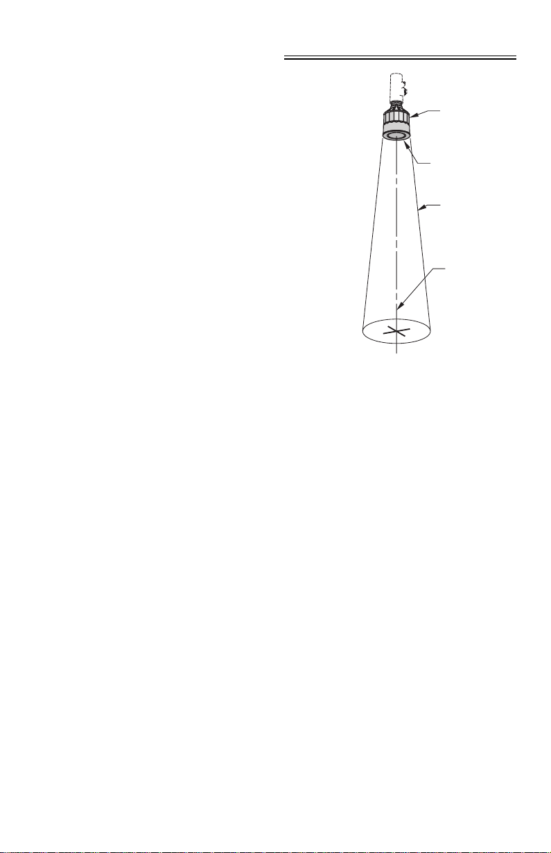
The transducer converts the electrical energy of the
transmit pulse from the transceiver into acoustical
energy. It then converts the acoustical energy of
the echo back into electrical energy for the
transceiver receiv e period.
The effective acoustical energy is emitted from
the transducer face and radiated outward,
decreasing in amplitude at a rate inversely
proportional to the square of the distance.
Maximum power is radiated axially (perpendicular)
from the transducer face in a line referred to as
the axis of transmission. Where power is reduced
by half (– 3 dB), a conical boundary defining the
sound beam, centered about the axis of transmission,
is established. The diametric measurement of the
cone in degrees defines the beam angle. Impedance
matching techniques are used to optimize the transfer of
power from the transducer into air and vice versa.
The XPS F series transducers incorporate an integral temperature sensor that reports the air
temperature at the transducer to the transceiver. The connection is transparent, in that both
the ultrasonic and temperature components of the transducer use the same leads.
transducer
transducer face
– 3 db
boundary
axis of
transmission,
perpendicular to
transducer face
Hazardous seal supplied by others to suit hazardous area classificaton.
PL-551 3
Page 4

SPECIFICATIONS
Model : XPS - 10 F
Measurement Range, m
( ft ) :
Frequency (kHz) : 43
Beam Angle : 12°
Environmental :
- location : indoor / outdoor
- altitude : 2000 m maximum
- ambient temp :
- pollution degree : 4
Construction :
- exposure : Kynar
- colour : slate gray
- mounting : 1" NPT conduit connection
- options : » factory flange to suit ANSI standard
» submergence shield, where flooding can occur
» split flange for field mounting to suit ANSI standard
- cable : 2 wire shielded / twisted, 0.5 mm
Supply Source : transducer shall only be supplied by a Milltronics certifi ed controller
Weight *, kg (lb) : 0.8 (1.7)
Separation : 365 m (1200 ft) from transducer
Approvals : FM Class 1 Div 1, Group A, B, C and D
FM Class 2 Div 1, Group E, F and G
see nameplate or consult Milltronics for current approvals
0.3 - 10
( 1 - 33 )
– 20 to 95 °C ( – 4 to 203 °F )
®
2
(20 AWG) PVC jacket
* approximate shipping weight of transducer with standard cable length
®
is registered trade mark of ELF Atochem
Kynar
PL-551 4
Page 5
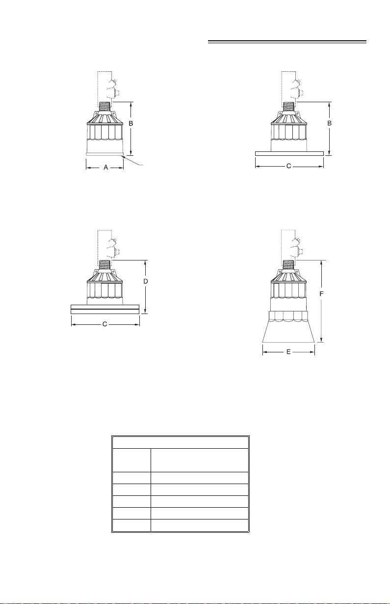
OUTLINE AND DIMENSIONS
radiating face
standard
optional flange
refer to associated
instructions
optional split flange
refer to associated instructions
Hazardous seal supplied by others to suit hazardous area classificaton.
Model
Dimension XPS - 10 F
A 86 mm (3.4")
B 122 mm (4.8")
C to suit ANSI standard
D* 128 mm (5.0")
E 124 mm (4.9")
F 152 mm (6.0")
* nominal
PL-551 5
optional submergence shield
refer to associated instructions
Page 6
MOUNTING
DO’S AND DON’TS
Mount the transducer so that it is
value
. Refer to the associated transceiver manual.
On liquid applications, the transducer must be mounted so that the axis of transmission is
perpendicular to the liquid surface.
On solids applications, a Milltronics Easy Aimer should be used to facilitate aiming of
the transducer.
Do not overtighten mounting
Secure installation by connecting a safety chain from the transducer to a structural member.
Consider the optional
temperature sensor
above the maximum material level by at least the blanking
. Hand tightening of the mounting hardware is sufficient.
when mounting the transducer.
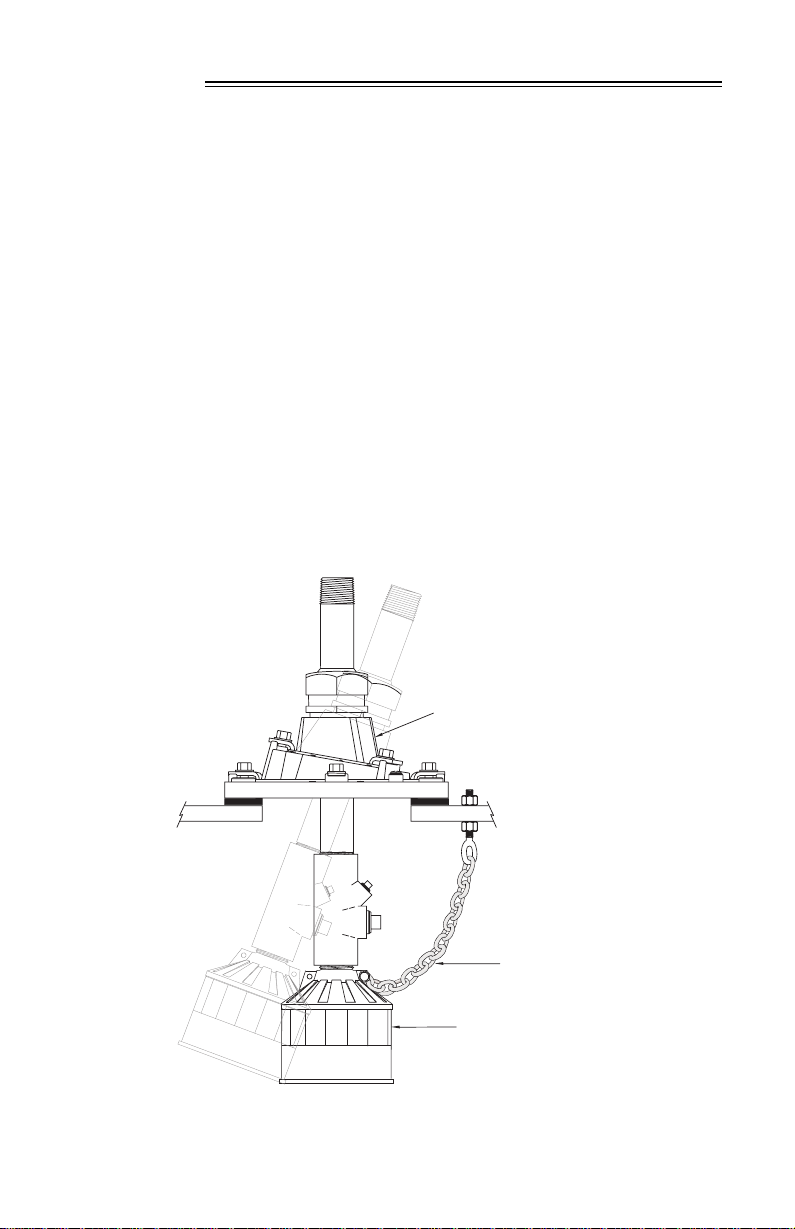
MOUNTING - SOLIDS APPLICATIONS
Easy Aimer
(typical model)
Hazardous seal supplied by others to suit hazardous area classificaton.
PL-551 6
safety chain
transducer
Page 7

MOUNTING - LIQUID APPLICATIONS
Flexible Conduit
safety
chain
Flexible conduit mounted transducer should
not be subjected to wind, vibration or jarring.
Bracket
flexible
conduit
steel channel
hazardous
seal
transducer
Submersible
rigid metal conduit
safety
chain
Submersible transducer, used in
applications where flooding is possible.
PL-551 7
hazardous seal
submergence
shield
Page 8

MOUNTING - LIQUID APPLICATIONS (cont’d)
Blind Flange
Flange, gasket, hazardous seal and hardware supplied by
customer. Refer to Liquid \ Applications - Standpipes.
nipple welded to blind flange
hazardous seal
Flanged
Customer flanged standpipe. If a metal flange must be welded
to pipe, refer to Liquid \ Applications - Standpipes.
PL-551 8
hazardous seal
factory flanged transducer
bolt
gasket
customer flange, flat face only
nut
Page 9

INTERCONNECTION
Milltronics transceiver ( typical )
Direct Connection
blk
2 Wire Extension
blk
wht
extend cable using 18
AWG shielded / twisted pair
junction box
Coaxial Extension
wht
drain / shield
drain / shield
PL-551 9
extend cable using RG - 62 A/U coax
for optimum noise immunity
Page 10

DO’S AND DON’TS
Installation shall only be performed by qualified personnel and
in accordance with local governing regulations.
Do not route cable openly.
For optimum isolation against electrical noise, run cable separately in a grounded
metal conduit.
Seal all thread connections to prevent ingress of moisture.
Do not run cable near high voltage or current runs, contactors and SCR control drives.
PL-551 10
Page 11

APPLICATIONS
The transducer is to be used only in the manner outlined in this instruction manual.
The transducer requires no cleaning or maintenance.
LIQUID APPLICATIONS - STILLING WELL / OCM
blind flange
air vent
TS-3 *
transducer
standpipe
bracing
standpipe inlet
primary element
stilling well inlet
Refer to Liquid \ Applications - Standpipes.
*
the use of a TS-3 temperature sensor provides better temperature tracking
stilling well
in applications where the temperature can change quickly.
PL-551 11
Page 12

LIQUID APPLICATIONS - SUBMERGENCE
In applications where flooding is possible the transducer▼ can be fitted with a submergence
shield. The shield acts as a bell to create an air pocket in front of the transducer face. The
associated transceiver
▼
interprets this as a flooding condition, and reacts accordingly.
Refer to transceiver manual for programming requirements.
hazardous seal
transducer
refer to associated instruction manual for assembly details.
*
▼
on applicable models.
PL-551 12
submergence shield
air pocket
*
Page 13

LIQUID APPLICATIONS - STANDPIPES
In many applications access must be made via a standpipe. In such cases, Milltronics can
provide factory bonded flanged transducers or split flange kit that will readily mate to the
flanged standpipe. Another option is to hang the transducer from a blind flange.
The standpipe length should be as short and the diameter as large as possible. As a rule of
thumb, the -3 dB cone of the sound beam should not intersect the standpipe wall in
applications opening into a vessel or larger area. Otherwise, additional blanking will be
required to compensate for the interference zone created by the opening.
flanged
transducer
no vessel
no
intersection
vessel
no additional blanking
transducer
can read
level inside
or below
standpipe
no additional blanking
required
nipple welded into
a blind flange
transducer
standpipe
end cut on a
45 ° angle
typically
required
PL-551 13
no additional blanking
vessel
near blanking extension
of 150 mm (6") past end of
standpipe may be required.
required
nipple welded into
blind flange
transducer
sound beam
intersects
reflection at
interference zone
created by opening
Page 14

LIQUID APPLICATIONS - VOLUME
‘ Alternate ’
‘ Preferred ’
‘ Bad ’
Maintain full level
for full calibration.
Above this level
erroneous readings
will result as level
has entered
blanking zone.
(shaded area)
Empty level for
‘alternate’ location.
Below this level, echo
would reflect away
from the transducer.
rise
beam
angle
tank
manufacturer’s
full level
span : corresponds to
tank manufacturer’s
empty level.
tank manufacturer’s
empty level
may require target to
obtain empty reading
discharge
1. Beam should not detect bin bottom. If this occurs use range extension parameters
(on transceivers where available) to omit false echoes. A 6° beam angle represents a
rise : run of about 20 : 1 (10 : 1 for 12°). In most tanks, the transducer should be
centered as much as possible (without interference from inlet) for optimum reading range.
2. Sound beam must be perpendicular to liquid surface.
If standpipe is used, refer to Liquid / Applications - Standpipes.
3. Echo has missed improperly leveled transducer.
4. When performing an empty or full calibration, the tank must contain its normal vapour and
be at its normal temperature.
5. Hazardous seal supplied by others to suit hazardous area classification.
PL-551 14
Page 15

LIQUID APPLICATIONS - WATER / WASTEWATER
DIFFERENTIAL LEVEL
PUMP CONTROL
PL-551 15
SEWAGE LIFT
Page 16

SOLIDS APPLICATIONS - TYPICAL
1
2
1. Transducer angled to avoid
seams in bin wall and aimed at
discharge in order to read bin
when empty.
2. Avoid intersecting bin wall
seams, structural members and
wall irregularities. Otherwise,
bin wall seams
filling profile
emptying profile
Easy Aimer
transducer
3
3. Transducer too close to material
inlet. Falling material will intersect
sound beam and cause erroneous
readings or loss of echo.
minimal angle
of repose
4
discharge
4. On fluid like solids, aim
transducer perpendicular to
material surface.
PL-551 16
5
5. On dual discharge bins, aim each
transducer at the discharge point.
Page 17

SOLIDS APPLICATIONS - SPECIAL
STORAGE BIN WITH AGITATOR
infeed
agitator
1. Transducer should be kept away from infeed.
2. Where agitators are in use, use the Agitator Discrimination parameter on
transceivers where available.
3. Transducer should be aimed away from wall projections.
4. Hazadous seal supplied by others to suit hazardous classifications,
DRYER - WOOD CHIPS
infeed
drag conveyor
typical low level
1. Transducer should be mounted perpendicular to slope of wood chips.
2. Hazadous seal supplied by others to suit hazardous classifications,
PL-551 17
typical high level
Page 18

PL-551 18
 Loading...