

Page 1

Interface Module
for Allen-Bradley Remote I/O
33455330
Rev 1.0
Instruction Manual
PL-533
March 1997
Technology based. Customer driven.
Page 2

Thank you for purchasing Milltronics’ products. We endeavour to design equipment that
is simple to use and reliable in its operation, with the aim of satisfying our customers’ needs.
Milltronics has been designing and manufacturing process equipment since 1954. Our
fields of expertise include ultrasonic level measurement, in-line weighing of dry bulk solids
and motion sensing.
Milltronics is established world wide through associate offices and representatives. Our network
is continually being refined to provide our customers with first rate sales information, engineering
assistance and after sales support.
For more details on our products and service, please contact us and we will provide you with
a listing of the offices or representatives nearest you.
Canada : 1954 Technology Dr., P.O. Box 4225,
Peterborough, Ontario, Canada K9J 7B1
Tel.: 705-745-2431 Fax: 705-741-0466
U.S.A. : 709 Stadium Drive, Arlington, Texas U.S.A. 76011
Tel.: 817-277-3543 Fax: 817-277-3894
England : Oak House, Bromyard Road, Worcester , England WR2 5XZ
Tel.: 01905-748404 Fax: 01905-748430
France : Parc de la Sainte Victoire, Bât. 5, 13590 Meyreuil, France
Tel.: +33 4 42 65 69 00 Fax: +33 4 42 58 63 95
Belgium : August van de Wielelei 97, 2100 Deurne, Antwerp, Belgium
Tel.: 03/326 45 54 Fax: 03/326 05 25
Mexico : Amores No. 1155, Col. Del Valle, 03100 Mexico D.F., Mexico
Tel.: 575-31-44 / 575-83-13 / 575-27-78 Fax: 575-26-86
Internet : http://www.milltronics.com
Page 3

TABLE OF CONTENTS
About this module . . . . . . . . . . . . . . . . . . . . . . . . . . . . . . . . . . . . . . . . . . . . . . . . . . . 4
Specifications . . . . . . . . . . . . . . . . . . . . . . . . . . . . . . . . . . . . . . . . . . . . . . . . . . . . . . 4
Installation . . . . . . . . . . . . . . . . . . . . . . . . . . . . . . . . . . . . . . . . . . . . . . . . . . . . . . . . . 5
Physical
Hardware Set Up
Software Set Up
Operation . . . . . . . . . . . . . . . . . . . . . . . . . . . . . . . . . . . . . . . . . . . . . . . . . . . . . . . . . 7
Application Layer . . . . . . . . . . . . . . . . . . . . . . . . . . . . . . . . . . . . . . . . . . . . . . . . . . . 8
Parameter Values
Numeric values
“Split values”
Text messages
Relay function codes
Block Transfers
Block Transfer Write
Block Transfer Read
Discrete I/O
Discrete Output Words
Discrete Input Words
Troubleshooting . . . . . . . . . . . . . . . . . . . . . . . . . . . . . . . . . . . . . . . . . . . . . . . . . . . 23
Generally…
Specifically…
==================================================================
3 PL-533
Page 4

ABOUT THIS MODULE
Milltronics SmartLinx module for Allen-Bradley is a ‘plug in’ communications circuit card
designed to interface any Milltronics SmartLinx compatible device to Allen-Bradley
Remote I/O.
The module may have been shipped installed in your unit, or shipped separate for site
installation. Refer to your associated Milltronics device instruction manual for details on
its location or physical installation.
=================================================================
SPECIFICATIONS
Electrical: compatible with any Milltronics SmartLinx compatible device and Allen-
Bradley Remote I/O
Physical: compatible with any Milltronics SmartLinx compatible device
Application: compatible with Allen-Bradley Remote I/O
Connection: 3-position terminal block for wire end
Termination: switch selectable, open or 82 Ω internal
Cable: Belden 9463 ‘Blue Hose’ or equivalent
============================================================================
PL-533 4
Page 5
INSTALLATION
================================================================================
PHYSICAL
Refer to associated Milltronics SmartLinx compatible device instruction manual for
location or installation of the module.
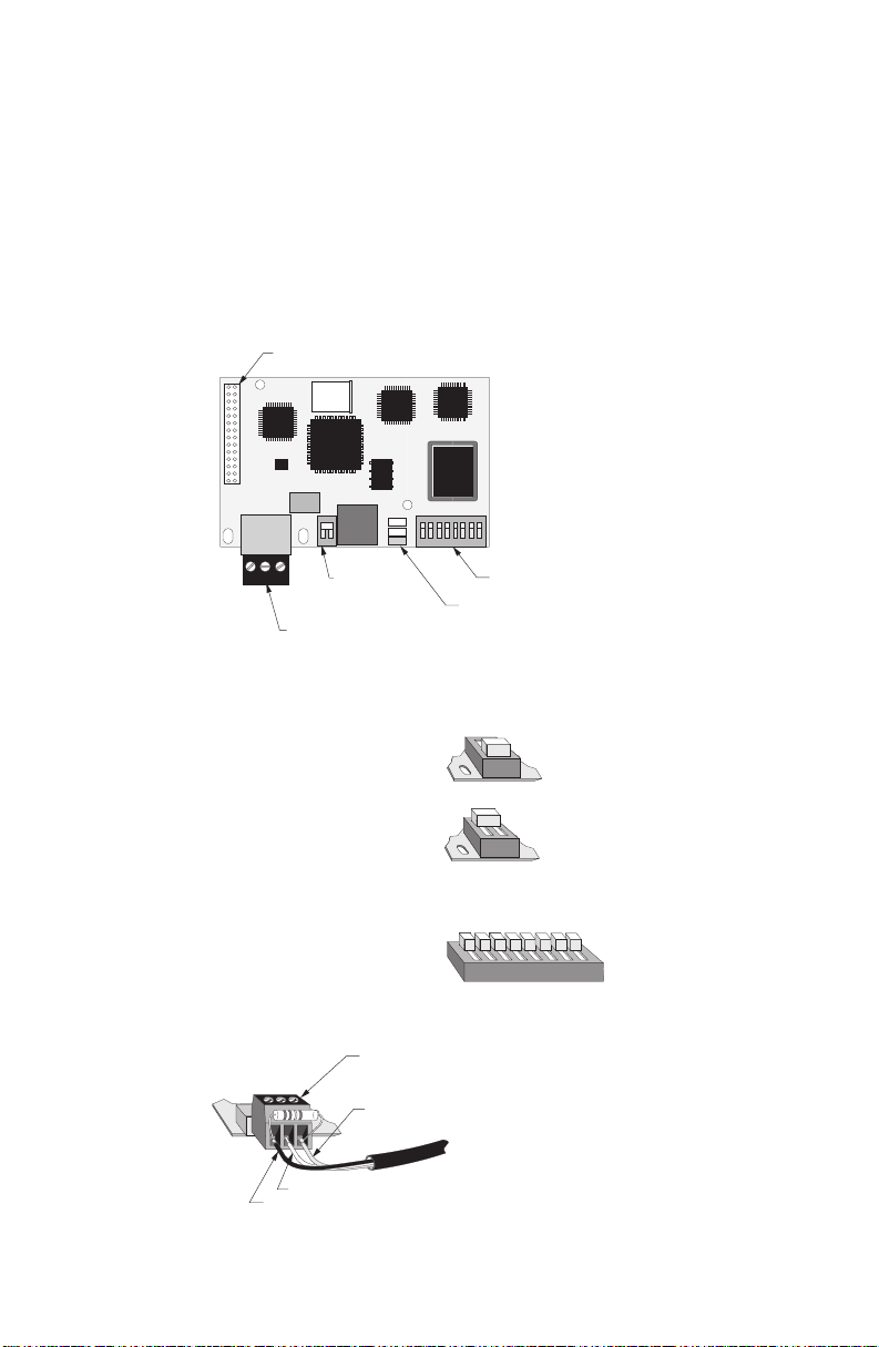
HARDWARE SETUP
SmartLinx module for Allen-Bradley Remote I/O
module connector (underside) to Milltronics device
termination
switch
cable connector
reserved switches
status LEDs (refer to Operation)
TERMINATION SWITCH
termination setting
open off
150 Ω external* off
82 Ω on
RESERVED SWITCH
setting
all on
CABLE CONNECTION
*termination resistor (as required)
clear
shield
blue
Connect using Belden 9463 ‘Blue Hose’ cable or equivalent and terminate (blue/clear)
according to Allen-Bradley specification and conventions.
5 PL-533
Page 6

SOFTWARE SETUP
GENERAL
It is recommended to set up the Milltronics device as a 1⁄4 rack size, to conserve remote
rack space available to the PLC. As discrete I/O operation is very limited when using 1⁄4
rack size configuration, block transfer read and write commands are recommended.
Avoid discrete I/O as it does not provide any advantage over block transfers. (Transfer
speed is not an issue, as transfer rates are much greater than the rate where new
readings are generated by the Milltronics device.)
It is also recommended to exercise caution when deciding how often to trigger the BTR
and BTW instructions. Too often increases the delay of all block transfers on the
Remote I/O link. A recommended guideline is to trigger the BTR and BTW instructions
no faster than every 0.3 seconds.
SPECIFIC PARAMETERS
P751 baud rate
Sets the baud rate for Remote I/O communication between
Milltronics device and Allen-Bradley.
values: 0 = 57.6 kbaud
1 = 115.2 kbaud
2 = 230.4 kbaud
The default value is 0.
P752 rack number
Enter the rack number (octal) that the Milltronics device has been assigned
on the Remote I/O link. The valid range is 01 – 73. Check your PLC manual
for the supported range.
The default value is 2.
P753 starting group
Sets the starting group number for the Milltronics device.
starting group rack size (P754)
values: 0 1, 2, 3 or full
2 1, 2 or 3 /4
4 1 or 2 /4
6 1/4
The default value is 0.
PL-533 6
Page 7

P754 rack size
Sets the discrete I/O address space. Valid settings are 1 to 4 quarter racks,
dependent upon the starting group (P753).
rack size starting group (P753)
values: 1/4 0, 2, 4 or 6
The default value is 0.
P755 last rack
The last rack is defined as the highest numbered rack on the Remote I/O link.
Determine the position of Milltronics device and set this parameter
accordingly.
value: 0 = not last
The default value is 0.
2/4 0, 2 or 4
3/4 0 or 2
full 0
1 = last
OPERATION
Communication on the Remote I/O link is indicated by the SmartLinx LEDs.
=======================================================================================
on module is powered
off no communication between bus and module
flash bus intact, Allen-Bradley PLC in program; or
Milltronics device set to different rack size
than PLC
on active communication
on not being scanned by PLC
7 PL-533
Page 8

APPLICATION LAYER
The application layer is the name given to the organization and format of the discrete
I/O and block transfer communications areas of the Milltronics device . All transactions
between the PLC and the Milltronics device are either reading parameter values from
the Milltronics device, or setting parameter values in the Milltronics device.
This manual refers to a 10 point level instrument; if your device has fewer than 10
points, you should ignore data in registers which represent non-existing points. Those
registers will still be present, but will contain undefined values.
===================================================================
PARAMETER VALUES
The Milltronics device parameters take on many values in various formats, as discussed
in the Milltronics device manual. For the convenience of the PLC programmer, those
values are converted to and from a 16-bit integer number, since those are easily
handled by most PLCs. This section describes that conversion process; later sections
detail where those values are in discrete I/O and block transfer addresses, and how to
get the parameters you need.
Numeric values
Numeric parameter values are by far the most common. For example, parameter P920
(Reading), returns a number representing the current reading (either level or volume,
depending on the Milltronics device configuration).
Numeric values may be requested or set in either units or percent of span, and may be
specified with a number of decimal places.
Numeric values must be in the range -10,000 to +10,000 to be valid. If a parameter is
requested and its value is more than +10,000, the number 32,767 is returned; if it is less
than -10,000, the number -32,768 is returned. If this happens, increase the number of
decimal places for that parameter.
If a parameter cannot be expressed in terms of percent (e.g. span), or has no
meaningful value, the special number 22,222 is returned. Try requesting the parameter
in units, or refer to the Milltronics device manual to understand the requested
parameter.
“Split” Values
Certain parameters are actually a pair of numbers separated by a colon, in the format
xx:yy.
One example is P807, Transducer Noise, where:
xx = the average noise value in dB
yy = the peak noise in dB.
PL-533 8
Page 9

The number which corresponds to xx:yy, either for reading or setting a parameter, is
determined by the following formula:
– for storing to the Milltronics device:
value = (xx + 128) x 256 + (yy + 128)
– for reading from the Milltronics device:
xx = (value / 256) - 128
yy = (value % 256) - 128
where % is the modulus operator. This can be computed by finding
the remainder of an integer divide-by-256.
It may simplify programming to notice:
xx = (most significant byte of value) - 128
yy = (least significant byte of value) - 128
Text messages
If an Milltronics device parameter returns a text message, that message is converted to
a corresponding number shown in the table below:
22222 invalid value
30000 off
30001 on
30002 ≡≡≡≡
30003 [ - - ]
30004 err
30005 err1
30006 open
30007 shrt
30008 pass
30009 fail
30010 hold
30011 lo
30012 hi
30013 de
30014 en
-32768 value is less than -10,000
32767 value is greater than 10,000
9 PL-533
Page 10

Relay function codes (parameter P111 only)
Relay function codes are represented by unique numbers.
.
OFF 0
ALARM 1
LL_ALARM 2
L_ALARM 3
H_ALARM 4
HH_ALARM 5
INSIDE_BAND 6
INSIDE_BAND_1 7
INSIDE_BAND_2 8
OUTSIDE_BAND 9
OUTSIDE_BAND_1 10
OUTSIDE_BAND_2 11
RATE_ALARM 12
RATE_ALARM_1 13
RATE_ALARM_2 14
TEMPERATURE_ALARM 15
LOE_ALARM 20
NON_SEQD 25 (for pump control)
UNKNOWN_MODE 200
PL-533 10
Page 11

BLOCK TRANSFERS
In order to read or write data via block transfers, the PLC has to be programmed
accordingly. Refer to the Allen-Bradley PLC documentation on how to write block
transfer read (BTR) and block transfer write (BTW) rungs in your PLC program.
This section describes the meaning of the data read and written in block transfers to the
Milltronics device.
The data provided by the Milltronics device in a BTR operation to the PLC is set by a
BTW operation.
Block Transfer Write
The words in the block transfer write operation allow access to the Milltronics devices in
two ways: Multiple Parameter Access (MPA) and Single Parameter Access (SPA).
word description
0 point on priority
1 parameter number, MPA
2 parameter index, MPA
3 decimal place, MPA
4 format, MPA
5 parameter number, SPA
6 point number, SPA
7 parameter index, SPA
8 value, SPA
9 decimal place, SPA
10 format, SPA
11 read/write flag, SPA
12 operating mode, SPA
Words 1 to 4 are MPA, allowing continuous monitoring in BTR words 21 – 30 of
selected parameters for points 1 – 10. Using these words does not allow changing of
the parameter value.
Words 5 to 12 are SPA, allowing continuous monitoring or demand programming of a
parameter for a given point, individually selected for each point.
11 PL-533
Page 12

BTW Word 0, Point-on-Priority
Bits 00–11 set the priority status of corresponding points 1–10.
bit 11 10 07 06 05 04 03 02 01 00
point 10 9 8 7 6 5 4 3 2 1
bit status 0 = normal
1 = priority
e.g. bit 11 10 07 06 05 04 03 02 01 00
status 0 0 0 0 0 0 0 1 0 1
points 3 and 1 are on priority scan
All other bits are reserved and should contain 0.
This word is ignored if the Milltronics device is configured as a full rack (P754 Rack Size
set to 4). In that case, use discrete output word 7 to control point-on-priority.
If this word is used to control point-on-priority, then the Milltronics device must be
configured to permit this. Parameter P720 must be set to 1 (manual, BIC-II or
SmartLinx) for each point to permit priority control for that point. To enable priority
control for all points, simply store ‘1’ to parameter P720, point ‘0.’
BTW Word 1: Parameter Number, MPA
Specifies the parameter number for the returned value in BTR words 21–30.
BTW Word 2: Parameter Index, MPA
Specifies the parameter index for the parameter returned in BTR words 21–30. This
word is ignored for parameters which don’t use indices.
Some specific Milltronics device parameters use indices to address the multiple values
stored within the single parameter.
For example, parameters P054 level breakpoints and P055 breakpoint volumes use the
index to specify which breakpoint to read. High-level-language programmers might think
of this index as an array index.
BTW Word 3: Decimal Place, MPA
Specifies the number of decimal places in each of the returned values in BTR words 21–30.
For example, a 1 would mean all returned values would have 1 decimal place, i.e. a
returned value of 5,213 should be interpreted as 521.3. This value may be negative,
indicating trailing zeros; for example if this word were -1, a returned value of 5,213
should be interpreted as 52,130.
BTW Word 4: Format, MPA
Sets the format for the returned values in BTR words 21 – 30.
0 = normal
1 = percent of span
PL-533 12
Page 13

The values written in BTW words 5–11 specify the parameter read
from or written to the Milltronics device. The parameter is written
repeatedly until a 0 is written to word 11.
This would override any keypad entry for the value specified by
BTW words 5–10 while BTW word 11 is set to 1.
BTW Word 5: Parameter, SPA
Specifies the parameter number.
BTW Word 6: Point, SPA
Specifies the point number for the parameter specified by BTW word 5.
BTW Word 7: Index, SPA
Specifies the index for the parameter specified by BTW word 5. This word is ignored for
parameters which don’t use multiple values.
Some specific Milltronics device parameters use indices to address the multiple values
stored within the single parameter.
For example, parameters P054 level breakpoints and P055 breakpoint volumes use the
index to specify which breakpoint to read. High-level-language programmers might think
of this index as an array index.
BTW Word 8: Value, SPA
This word contains the value to be written to the parameter specified by BTW words
5–7, if BTW word 11 is set to 1. If BTW word 11 is set 0, this word is ignored. The
format of this word is specified by BTW words 9–10.
BTW Word 9: Decimal, SPA
This word specifies the number of decimal places for the value in BTW word 8, and also
for the parameter value returned in BTR word 38.
e.g.: given: BTW word 8 = 5,213
BTW word 9 = 1
BTW word 10 = 0
BTW word 11 = 1
then: the value is interpreted as 521.3 units and stored in the
Milltronics device.
13 PL-533
Page 14

given: BTW word 9 = -1
BTW word 10 = 0
BTW word 11 = 0
BTR word 38 = 5,213
then: the returned value in BTR word 38 is interpreted as 52,130.
BTW Word 10: Format, SPA
This word sets the format for the value in BTW word 8.
0 = normal
1 = percent of span
BTW Word 11: Read/Write Flag, SPA
This word instructs the read/write application of word 8.
0 = read parameter as described by words 5, 6, 7, 9 and 10; word 8 ignored
1= set parameter to the value described by words 5–10
BTW Word 12: Operating Mode, SPA
This word sets the operating mode of the Milltronics device. The device changes mode
only when the status of the bit changes.
The operating mode can be equally set via the device keypad.
bit status 0 = run mode
1 = program mode
PL-533 14
Page 15

Block Transfer Read
Values returned in the words in the block transfer read are in response to the block
transfer write to the Milltronics device.
Words 0 through 20 have values with fixed meanings and formats.
Words 21 through 34 have values returned in response to BTW words 1 through 4, for
Multiple Parameter Access (MPA).
Words 35 through 41 are values returned in response to BTW words 5 through 12 for
Single Parameter Access (SPA).
words description
0 point status
1–10 point reading
11–20 point alarm and status
21–30 returned values, MPA
31 decimal place, MPA
32 format, MPA
33 parameter number, MPA
34 parameter index, MPA
35 parameter, SPA
36 transducer, SPA
37 index, SPA
38 value, SPA
39 decimal place, SPA
40 format, SPA
41 read/write flag, SPA
BTR Word 0:
bit description
(octal)
00–11: point status
indicate the operation of the points 1–10.
bit 11 10 07 06 05 04 03 02 01 00
point 10 9 8 7 6 5 4 3 2 1
If a bit status is 1, the corresponding point is deemed to be operational,
based on the criteria defined by BTR words 11–20, bits 00–03. If the bit
status is 0, then the corresponding point is deemed non-operational. To
further diagnose a point’s operation, examine the corresponding word 11
through 20.
If a bit status is 1, then for the corresponding point alarm word 11–20, one or
more of the alarm bits 00–03 must be 1 to indicate the operational problem.
15 PL-533
Page 16

12: operating mode
0 = device in ‘run’ mode
1 = device in ‘program’ mode
13–17: reserved
These bits are reserved and set to 0.
BTR Words 1–10: Point Reading
These words contain the value of parameter P920 (Reading) for points 1–10,
respectively. The reading is expressed as a percent of full scale, multiplied by 100,
giving a range of 0–10,000 which corresponds to 0.00%–100.00%. Refer to the
Milltronics device documentation for a definition of ‘P920’.
Note these values may contain numeric level data for inoperative or malfunctioning
points; refer to BTR word 0, and BTR words 11–20 for the actual operational status of
the measurement points.
BTR Words 11–20: Point Alarm and Status
These words contain the corresponding alarm and status bits for point 1–10,
respectively.
Bit status: 0 = false
1 = true
bit description
(octal)
00 point not in operation
01 point failsafe timer expired
02 point failed (cable shorted, open, or transceiver problem)
03 point temperature sensor failed
04–14 reserved for future use
15 level emptying
16 level filling
17 scan mode priority
BTR Words 21–30: Returned Values, MPA
These words contain values requested by writing to words 1–4. The type of data and
format are specified with that request, and returned in block transfer read words 31–34.
PL-533 16
Page 17

BTR Word 31: Decimal Place, MPA
This word specifies the number of decimal places in each of the returned values in BTR
words 21–30.
e.g.: given: BTR word 21 = 5,213
BTR word 31 = 1
then: the returned value is interpreted as 521.3
given: BTR word 21 = 5,213
BTR word 31 = -1
then: the returned value is interpreted as 52,130
BTR Word 32: Format, MPA
This word sets the format for the returned values.
bit status description
0 normal
1 percent of span
BTR Words 33 and 34: Parameter Number and Index, MPA
These words contain the last values written to block transfer write words 1 and 2,
respectively. These words indicate what information is contained in returned values
1–10 (BTR words 21–30). These words are provided since there can be a delay
between writing a request via a block transfer write, and the appearance of the
requested values 1–10 (BTR words 21–30).
BTR Words 35–37 and 39–41:
Parameter Number/Point/Index and Decimal Place/Format/Flag, SPA
These words contain the last values written to BTW words 5–7 and 9–11, respectively.
They confirm that the parameter value has been written. These words are not updated
until the value has been successfully transferred and stored in the Milltronics device.
BTR Word 38: Value, SPA
This word contains the current value of the parameter identified by BTR words 35–37
and 39–40, regardless of the value of BTW word 11 (write flag).
If this value is different from what was written in BTW word 8, after BTR words 35–37
and 39–40 have been updated and match BTW words 5–7 and 9–10, respectively, then
the parameter was not stored. Try placing the Milltronics device in program mode.
17 PL-533
Page 18

DISCRETE I/O
The values returned in the discrete input words are determined by what has been
written into the discrete output words. By writing the correct words, values stored in
parameters can be accessed.
Discrete I/O does not allow write access to the parameters. That is, parameters cannot
be changed via a Remote I/O. In order to effect this type of operation, communication
must be carried out using Block Transfer. However, output word 7 allows scan point
priority of the Milltronics device to be altered.
The number of discrete input and output words available is determined by the rack size
as configured on the SmartLinx module. Each 1/4 rack allows two words each for
discrete inputs and outputs.
rack size number of discrete input or words
discrete output words
1/4 rack 2 0, 1
1/2 rack 4 0, 1, 2, 3
3/4 rack 6 0, 1, 2, 3, 4, 5
full rack 8 0, 1, 2, 3, 4, 5, 6, 7
In full rack configuration, discrete output word 7 may be used to configure the returned
data in discrete input word 7. This data is written in output word 7, bits 0–9 where each
bit corresponds to a transducer 1–10. The meaning of those bits is determined by
writing to bits 10–15 of output word 7, as described in the following section.
It is convenient to note the similarity between the input and output areas.
Discrete Output Words
output word description
0 communication control
1 point and parameter number, word 1
2 point and parameter number, word 2
3 point and parameter number, word 3
4 point and parameter number, word 4
5 point and parameter number, word 5
6 point and parameter number, word 6
7 point status control
PL-533 18
Page 19

Output Word 0: Communication Control
bits description
(octal)
00–07: reserved
These bits are reserved for PLC use. They may contain any value, and
therefore should not be relied upon to contain any expected value. These bits
should be ignored, or ‘masked off.’
10–11: reserved
These bits are reserved for future Milltronics use and should be set to 0.
12–14: decimal
Contains the value which indicates where the decimal place should be, for all
of the returned values 1–6. For example, a 2 indicates the decimal should be
shifted 2 places to the left or right (as determined by bit 15).
15: decimal shift
Determines the direction of shift for the decimal (bits 12–14):
0 = shift left
1 = shift right
If bits 12–14 are all 0, this bit may be ignored.
16: numerical format
Determines the numerical format for the data returned in discrete input words
1–6: 0 = normal
1 = percent of span
If a parameter isn’t available as a percent of span, the undefined value
(22,222) is returned.
17: echo
The value of this bit is echoed back from the discrete output word 0, bit 17.
This bit is only used for test purposes.
19 PL-533
Page 20

Output Words 1–6: Point and Parameter Numbers, Words 1–6
The words determine what will be returned in discrete input words 1–6. These words
contain both the parameter and the point to be read, as determined by the following
formula:
Word 1–6 = (point x 1,000) + parameter
For example, if it was desired to read the level of transducer 6 back in discrete input
word 1, where level is returned in parameter 920, the value 6,920 decimal would be
written to discrete output word 1.
In this manner, up to 6 values may be read in a full rack, or just 1 value in a quarter
rack. The choice must be made as to how many values must be read simultaneously
(i.e. data transfer bandwidth), and how much rack space may be occupied.
Any combination is possible; for example, with a full rack 6 levels from 6 points can be
read simultaneously, 3 parameters each from 2 points, 6 parameters from 1 transducer,
or any other desired combination of the 6 words available in the full rack configuration.
Output Word 7: Point Status
bits description
(octal)
00–11: point i.d.
Each bit confirms the association of the point(s) identified, to the request for
the point status, bits 12–17.
bit 11 10 07 06 05 04 03 02 01 00
point 10 9 8 7 6 5 4 3 2 1
e.g. bits 11 10 07 06 05 04 03 02 01 00
status 0 0 0 0 0 0 0 1 0 1
points 3 and 1 are identified.
12–17: point status command
Indicates the status of the points identified by bits 00–11:
bits 17 16 15 14 13 12
0 0 0 0 0 0 = point in alarm
0 0 0 0 0 1 = point-on-priority
For example, to put points 1 and 3 on priority scan, store the binary value
0000010000000101 to discrete output word 7; the actual point-on-priority status is
returned in discrete input word 7. For another example, store the value 0 to this word,
and the point alarm status is returned in discrete input word 7.
If this word is used to control point-on-priority, then the Milltronics device must be
configured to permit this. Parameter P720 must be set to 1 (manual, BIC-II or
SmartLinx) for each point to permit priority control for that point. To enable priority
control for all points, simply store ‘1’ to parameter P720, point ‘0.’
PL-533 20
Page 21

Discrete Input Words
input description
word
0 communication status
1 returned value 1
2 returned value 2
3 returned value 3
4 returned value 4
5 returned value 5
6 returned value 6
7 point status
Input Word 0: Communication Status
bits description
(octal)
00–07: reserved
Reserved for PLC use. These may contain any value, and should not be
relied upon to contain any expected value. These bits should be ignored, or
‘masked off.’
10–11: rack size
Contains the rack size as configured: 00 = 1/4 rack
This value may be useful for PLC programs to automatically ‘know’ how
much data is available.
12–14: decimal
Contains the value indicating the decimal place for all of the returned values
1–6. For example, a value of 2 indicates the decimal should be shifted 2
places to the left or right (as determined by bit 15). A zero indicates no shift.
15: decimal shift
Determines the direction of shift for the decimal (bits 12–14):
0 = shift left
1 = shift right
If bits 12–14 are all 0, this bit may be ignored.
16: numerical format
Indicates the numerical format for the returned values:
0 = normal
1 = % of span
01=1/2
10=3/4
11= full
21 PL-533
Page 22

17: echo
The value of this bit is echoed back from the discrete output word 0, bit 17.
This bit is only used for test purposes.
Example:
Input word 0 is 2,048 and input word 1 is 5,123 decimal. Input word 0 expressed in
binary is 0000 1000 0000 0000. Bits 0–7 must be ignored. Bits 10–11 indicate the
Milltronics device is configured as 1/4 rack. Bit 16 indicates the returned value is in
engineering units. Bits 12–14 are binary 010, or 2, indicating two decimal places in the
returned value. Bit 15 is 0, indicating the decimal place of the returned value should be
shifted left. So, the value 5,123 should be read as 51.23 engineering units, as specified
in the Milltronics device.
Input Words 1–6: Returned Values, Words 1–6
These words contain parameter number and value from the Milltronics device, as
determined by the values written to the corresponding discrete output words 1–6.
Returned values are between -10,000 and 10,000 inclusive, otherwise refer to
Troubleshooting.
Input Word 7: Point Status
bits description
(octal)
00–11: point i.d.
Each bit confirms the association of the point(s) identified, to the request for
the point status, bits 12–17.
bit 11 10 07 06 05 04 03 02 01 00
point 10 9 8 7 6 5 4 3 2 1
e.g. bits 11 10 07 06 05 04 03 02 01 00
status 0 0 0 0 0 0 0 1 0 1
points 3 and 1 are identified
12–17: point status
Indicates the status of the points identified by bits 00–11:
bits 17 16 15 14 13 12
0 0 0 0 0 0 = point in alarm
0 0 0 0 0 1 = point-on-priority
Refer to discrete output word 7 for instructions on how to control whether priority or
alarm status is returned in this word.
PL-533 22
Page 23

TROUBLESHOOTING
GENERALLY…
In all cases, first check that the SmartLinx module has passed its on-going built-in self
test (device parameter P790). The result should be PASS .
If FAIL is indicated, either the module is defective, or the module connector on the
Milltronics device is defective.
If “ERR1” is indicated, the Milltronics software doesn’t recognize the ID number of the
installed module. Please contact Milltronics or your distributor for instructions and/or
upgraded Milltronics SmartLinx compatible device software.
SPECIFICALLY…
Q1: I connected the Milltronics device to my remote I/O link. All
communications have stopped, and I have rack fault bits set on all remote
racks in the scan list.
A1.1: Make sure the Milltronics device is connected and terminated correctly and in
agreement with all Allen-Bradley remote I/O wiring practices (please contact your
Allen-Bradley representative for the latest guidelines).
A1.2: Make sure the termination resistor switch on the SmartLinx module is set
correctly. Improper termination can interfere with proper remote I/O operation.
==================================================================
Q2: I connected the Milltronics device to my remote I/O link. Communication
with certain racks has stopped, and I have rack fault bits set on those
remote racks.
A2.1: Make sure the Milltronics device is connected and terminated correctly and in
agreement with all Allen-Bradley remote I/O wiring practices (please contact your
Allen-Bradley representative for the latest guidelines).
A2.2: Make sure the termination resistor switch on the SmartLinx module is set
correctly. Improper termination can interfere with proper remote I/O operation.
A2.3: Check that those remote I/O devices have different rack numbers and starting
groups from the Milltronics device.
Q3: My PLC indicates a rack fault where the Milltronics device is addressed on
the remote I/O link, but all other devices operate properly.
A3.1: Check the baud rate, rack number, starting group, rack size and last rack
settings on the Milltronics device (P751-P755, respectively), and make sure they
match the entry in the PLC’s scan list.
23 PL-533
Page 24

A3.2: Check the rack number (P752) on the Milltronics device; some Allen-Bradley
PLCs can accept only a limited number of racks. Try setting the rack number to a
lower available rack number.
A3.3: Check that no other devices connected to this remote I/O link have been set to
the same rack number and starting group as the Milltronics device.
A3.4: Make sure the Milltronics device is connected and terminated correctly and in
agreement with all Allen-Bradley remote I/O wiring practices (please contact your
Allen-Bradley representative for the latest guidelines).
A3.5: Make sure the termination resistor switch on the SmartLinx module is set
correctly. Improper termination can interfere with proper remote I/O operation.
Q4: Choosing the remote I/O Autoconfigure from my PLC programming
software doesn’t show the Milltronics device on the remote I/O link.
A4.1: Check the baud rate setting (P751) on the Milltronics device; it should match the
baud rate of the remote I/O scanner port on the PLC.
A4.2: Check the rack number (P752) on the Milltronics device; some Allen-Bradley
PLCs may accept only a limited number of racks. Try setting the rack number to
a lower available rack number.
A4.3: Try manually adding the Milltronics device to the PLC remote I/O scan list. If the
problem persists, contact Milltronics technical support.
Q5: The Milltronics device indicates it is being scanned, but the PLC indicates
a rack fault at that address.
A5.1: Check the rack size setting (P754); make sure it matches the rack size in the
PLC’s remote I/O scan list.
Q6: My PLC is scanning the Milltronics device with no rack faults, but the data
I’m reading makes no sense.
A6.1: Make sure the PLC is actually addressing the Milltronics device, and that no
other units are addressed to the same remote I/O rack number and starting
group. The PLC might be reading another device at the same rack number and
starting group.
A6.2: Check the information you’ve written to the discrete output area or block transfer
write area. Most of the information returned depends on what (configuration)
information was written to the Milltronics device.
PL-533 24
Page 25

Q7: I tried to set an Milltronics device parameter using a block transfer write,
but the parameter remains unchanged.
A7.1: Some parameters can only be changed when the Milltronics device isn’t
scanning. Try putting the Milltronics device in program mode, either using the
keypad or the run/program mode bit in the discrete output image table. Its
address is O:xxy/10,
where: xx = Milltronics device rack number and
y = starting group
Q8: No matter what rack number the Milltronics device is set for (P752), the
Milltronics device always appears at another (constant) rack number.
A8.1: The SmartLinx module’s reserved DIP switches 3–8 can override the Milltronics
device rack number setting (P752). Make sure all switches on the ‘reserved’ DIP
on the module are ‘on’.
Q9: No matter what baud rate the Milltronics device is set for (P752), the
Milltronics device always uses another (constant) baud rate.
A9.1: The SmartLinx module’s reserved DIP switches 1–2 can override the Milltronics
device baud rate setting (P752). Make sure all switches on the ‘reserved’ DIP on
the module are ‘on’.
Q10: After connecting the Milltronics device to the remote I/O and programming
block transfer commands, the transfer rate of other block transfers on the
remote I/O is slower.
A10.1: Try triggering the Milltronics device block transfer instructions less frequently, to
allow other block transfers to take place.
25 PL-533
 Loading...