

Page 1
MWL
MilltronicsWeight Lifter
Instruction Manual
June 2001
Page 2

Safety Guidelines
Warning notices must be observed to ensure personal safety as well as that of others, and to
protect the product and the connected eq uip m ent . These w ar ning notices are accompanied
by a clarification of the level of caution to be observed.
Qualified Personnel
This device/system may only be set up and operated in conjunction with this manual.
Qualified personnel are on ly authorized to install and operate this equipment in accordance
with established safety practices and standards.
Warning: This product can only function properly and safely if it is correctly transported,
stored, installed, set up, oper at ed, and maintained.
Note: Always use product in accordance with specifications.
Copyright Siemens Milltronics Process
Disclaimer of Liability
Instruments Inc. 2000. All Rights Reserved
This document is available in bound version and in
electronic version. We encourage users to
purchase authorized bound manuals, or t o view
electronic versions as designed and authored by
Siemens Milltronics Process Instruments Inc.
Siemens Milltronics Process Instruments Inc. will
not be responsible for the content s of partial or
whole reproductions of either bound or electronic
versions.
MILLTRONICS®is a registered t rademark of Siemens Milltronics Process Instruments Inc.
Contact SMPI Technical Publications at the following address:
Technical Publications
Siemens Milltronics Process Instruments Inc.
1954 Technology Drive, P.O. Box 4225
Peterborough, Ontario, Ca nad a, K9J 7B1
Email: techpubs@milltronics.com
While we have verified the contents of
this manual for agreement with t he
instrumentation described, variations
remain possible. Thus we cannot
guarantee full agreement. The
contents of this manual are regularly
reviewed and corrections are included
in subsequent editions. We welc ome
all suggestions for improvement.
Technical data subject to change.
For the library of SMPI instruction manuals, visit our Web site: www.milltronics.com
© Siemens Milltronics Process Instruments Inc. 2001
Page 3

Table of Contents
Milltronics Weight Lifter (MWL): Introduction ..............................................................2
Applications .............................................................................................................................................. 2
MWL Components ..................................................................................................................................3
Calibration Weight Arrangement ..............................................................................................4
Specifications ......................................................................................................................5
Belt Width .....................................................................................................................................5
Idler Spacing ................................................................................................................................5
Calibration Weight Capacity .....................................................................................................5
Crank Arm .....................................................................................................................................5
Calibration Weight Dimensions ..............................................................................................5
Mounting Dimensions ................................................................................................................5
Approvals ......................................................................................................................................5
Installation ........................................................................................................................... 6
Drill left and right crank body mounting holes .....................................................................6
Mount left-handed and right-handed crank body ...............................................................7
Mount torque shaft / Check clearance for conveyor belt .................................................8
Install crank handle ....................................................................................................................9
Test the unloaded MWL / Align crank bodies ...................................................................10
Install calibration weights / Check for clearance .............................................................11
Test the loaded MWL ...............................................................................................................14
Shim the MWL (if required) / Recheck base-bar weight for clearance ......................15
Operation ................ ............................... ................................. ............................... .............17
Applying calibration weights ..................................................................................................17
Storing calibration weights .....................................................................................................17
Storing crank handle ................................................................................................................17
Maintenance Procedures ................................................................................................19
Removing material accumulation ...........................................................................................19
Greasing......................................................................................................................................... 19
Appendix I: Installation Drawings .................................................................................20
MWL Installation Drawing for the MUS-STD Standard Duty Belt Scale ................................20
MWL Installation Drawing for the MUS-HD Heavy Duty Belt Scale .......................................21
Retrofitting an MUS-HD Heavy Duty Belt Scale: ...............................................................22
MWL Installation Drawing for the MSI or MMI Belt Scale ........................................................23
Retrofitting an MSI or MMI Belt Scale: ...............................................................................23
Appendix II: Customer Calculation Sheet .................................................................... 27
Calculation of Total Calibration Weight Mass ...................................................................27
Calculation of Load Reference Values .................................................................................27
Using the Factoring Function of the Belt Scale Integrator .............................................28
7ML19981CR01 Milltronics Weight Lifter MWL – Instruction Manual Page 1
Page 4

Milltronics Weight Lifter (MWL):
Introduction
Note: Please follow the installation and operating procedures to ensure a quick,
trouble-free installation, and to allow for the maximum accuracy and reliability of your
Milltronics Weighing System.
The Milltronics Weight Lifter (MWL) mechanically raises and lowers the static
calibration weights used to calibrate Milltronics belt scales. It stores the weights
securely between the belt strands, above the calibration-weight support arms, and
allows the operator to lower and apply the weights safely without having to lean into the
conveyor.
The MWL is manually operated, and utilizes a high mechanical advantage to enable
weights up to 225 Kg (500 lb) to be applied with very limited effort. The crank handle can
be attached to either the left or right crank body. It uses 4 revolutions for full range of
motion, and can be removed and stored for safety on the locking ball-pin which secures
the MWL when it is not in use.
Two lifting pads support a base-bar weight above the calibration-weight supports of the
belt scale: either flat bar or horseshoe style calibration weights are available. Locating
notches in the base-bar weight engage the calibration weights securely on the lifting pads
in the stored position, and the worm gear drive locks the lifting pads in place. A manuallyapplied locking-pin secures the MWL when the calibration-weights are in the stored
position.
Applications
The MWL is designed to work with the following Milltronics belt scales:
• MUS-STD MIlltronics Standard Universal Scale
• MUS-HD Milltronics Heavy-Duty Universal Scale
• MSI Milltronics Single Idler Scale
• MMI Milltronics Multiple Idler Scale (combination of 2 MSI Scales)
Belt Scale Manuals can be downloaded from the Milltronics website at:
www.Milltronics.com
Page 2 Milltronics Weight Lifter MWL – Instruction Manual 7ML19981CR01
Page 5

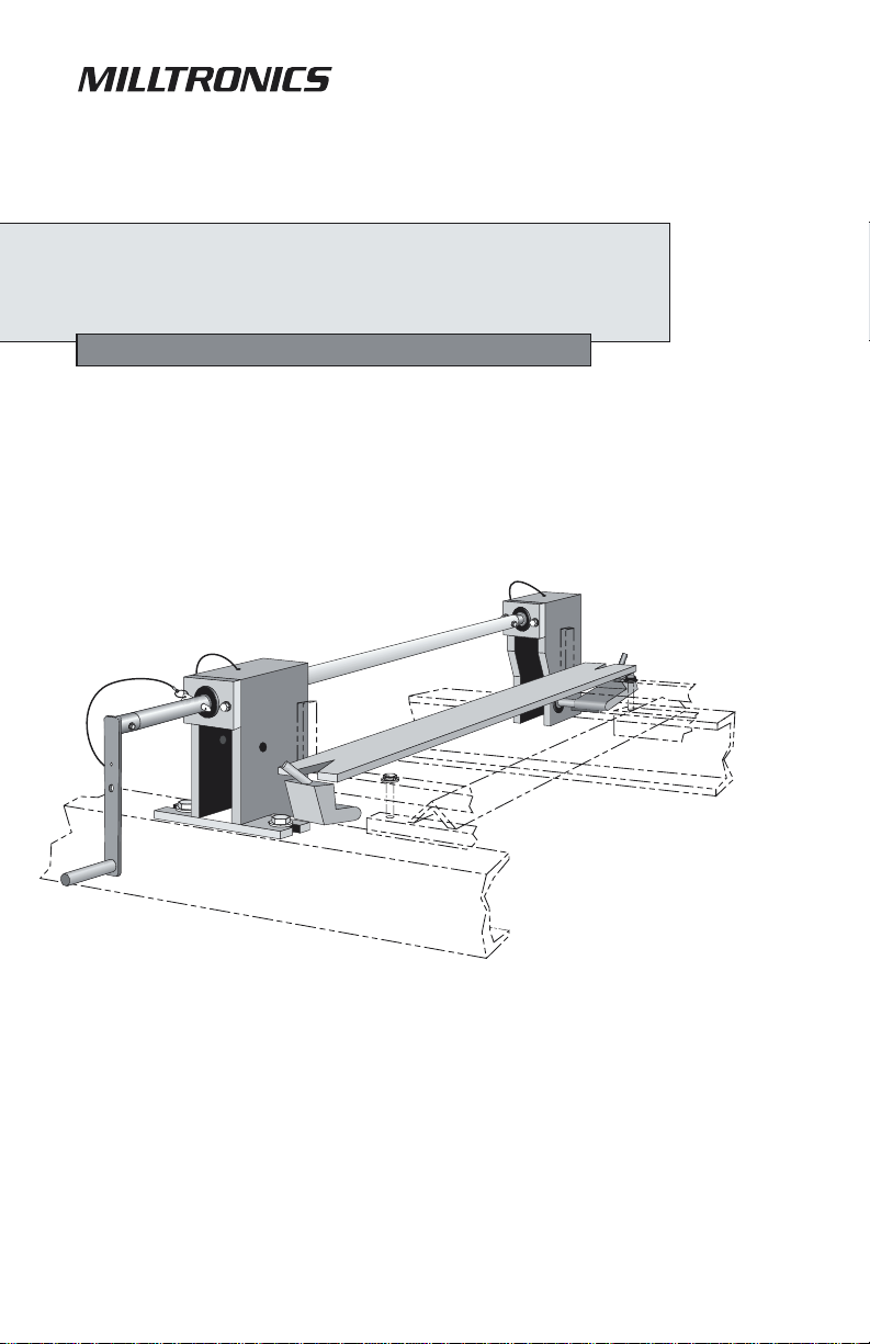
MWL Components
• a left-handed and right-handed crank body, each connected to a lifting-pad with guide-pin
• torque tube, to connect the left and right crank shafts
• crank handle, to be mounted to either the left or right input shaft
• optional shaft extension; adds 102mm (4") to handle shaft length
• base-bar weight (either flat bar or horshoe style) to support other supplied calibration
weights
• U-clamp to secure flat bar calibration weights
Shaft Extension
(optional)
Input Shaft (2)
Crank
Handle
Connecting Shaft
Torq ue Tu be
Torq ue Tu be
Right-handed
Crank Body
Lifting-pad (2)
Guide-pin (2)
Connecting Shaft (2)
Left-handed Crank Body
Base-bar Weight
Cut-away view of Gear Drive
(Left-hand, clockwise-rotating crank-body shown)
Worm Gear
Travel Sto p
Input Shaft
Guide-pin
Lifting-pad (lifts
as it rotates)
Removable
Travel Sto p
Plate Guide
Drive Plate
Output Shaft
Crank Handle
7ML19981CR01 Milltronics Weight Lifter MWL – Instruction Manual Page 3
Page 6
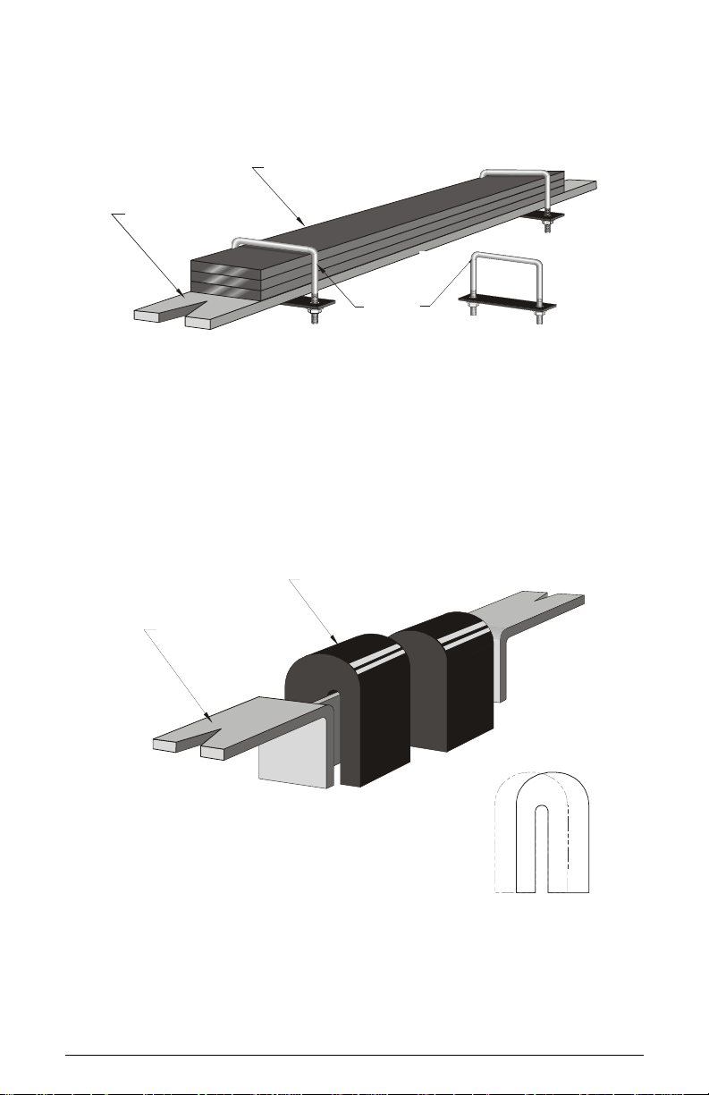
Calibration Weight Arrangement
Flat Bar Style Calibration Weights
Flat Bar Calibration Weights
Flat Bar Base-bar Weight
U-bracket
(supplied with
MWL)
Horseshoe Style Calibration Weights
Horseshoe-style Calibration Weights
Horseshoe-style
Base-bar Weight
The horseshoe weights are not symmetrical:
an offset channel locates them on the base-bar weight.
Rotate alternate weights through 180
are staggered, to stabilize the base-bar weight.
o
so that the weights
offset
Page 4 Milltronics Weight Lifter MWL – Instruction Manual 7ML19981CR01
Page 7

Specifications
Belt Width
• MUS-STD Standard Duty: up to 1000mm; CEMA width 42"
• MUS-HD Heavy Duty: 1200mm and up; CEMA width 48" : can also be applied to
narrower conveyors
• MSI Single Idler: 500 to 2000mm; CEMA width 18" to 84" (prepared for use
with MWL)
• MMI Dual Idler: consists of 2 MSI scales, 2 MWL units are required
Idler Spacing
• Minimum of 610mm (24")
Calibration Weight Capacity
• MUS-STD: up to 175 lb (80 kg)
• MUS-HD: up to 350 lb (160 kg)
• MSI singly, (or MMI system): up to 500 lb (225 kg)
Crank Arm
• Mechanical Advantage: 20:1
• Number of Revolutions required for raising or lowering: 4
Calibration Weight Dimensions
Idler Mounting Stance + 65mm (2.56")
Mounting Dimensions
• See detail installation drawings on page 20, page 21, and page 23, for MUS-STD
Standard Duty, MUS-HD Heavy Duty, and MSI Single Idler belt scales.
Approvals
• The MWL Milltronics Weight Lifter is in compliance with Directive 98/37/EC.
7ML19981CR01 Milltronics Weight Lifter MWL – Instruction Manual Page 5
Page 8

Installation
The Milltronics belt scale must be completely installed before you install the MWL.
Please refer to the belt scale installation manual for installation details.
Note: Check that there will be sufficient clearance for the MWL. (See detail, Check
Clearance for Conveyor Belt: page 8.) Clearance can be created artificially by
shimming the idlers in the scale area.
The MWL installation has eight stages:
• Drilling the crank body mounting holes
• Mounting the crank bodies
• Mounting the torque shaft
• Installing the crank handle
• Testing the unloaded MWL
• Installing the calibration weights
• Testing the loaded MWL
• Shimming the MWL (if required)
1. Drill left and right crank body mounting holes
• Refer to the appropriate MWL installation drawing for your Milltronics belt
scale.
• Measure and mark the locations of the mounting holes for each of the crank
bodies. The left-handed unit turns clockwise to raise weights and the righthanded unit turns counter-clockwise: handing is marked on the crank bodies.
• Drill these holes as specified for 12mm (1/2") mounting hardware.
Page 6 Milltronics Weight Lifter MWL – Instruction Manual 7ML19981CR01
Page 9
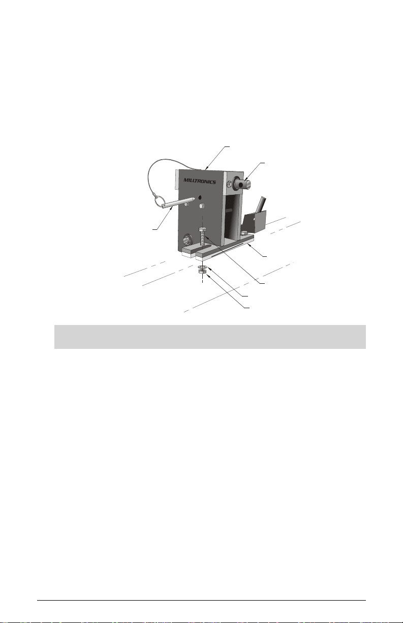
2. Mount left-handed and right-handed crank body
• Refer to the shim thickness tables on page 15 to determine whether you need to
shim the MWL. Shimming is not always required: it is more likely to be required
with the MUS scale, and less likely with the other models.
• If necessary, select and position the appropriate size shim(s).
• Loosely mount each crank body to the conveyor stringers using 12mm (1/2")
bolts, nuts, and washers.
Right-hand (counter-clockwise rotating) Crank Body Shown
Crank body
Input shaft
Locking ballpin tethered
to crank body
Shim (if required)
Bolt
Wash er
Nut
Note: The crank bodies must be left loose to allow for the torque shaft installation.
7ML19981CR01 Milltronics Weight Lifter MWL – Instruction Manual Page 7
Page 10
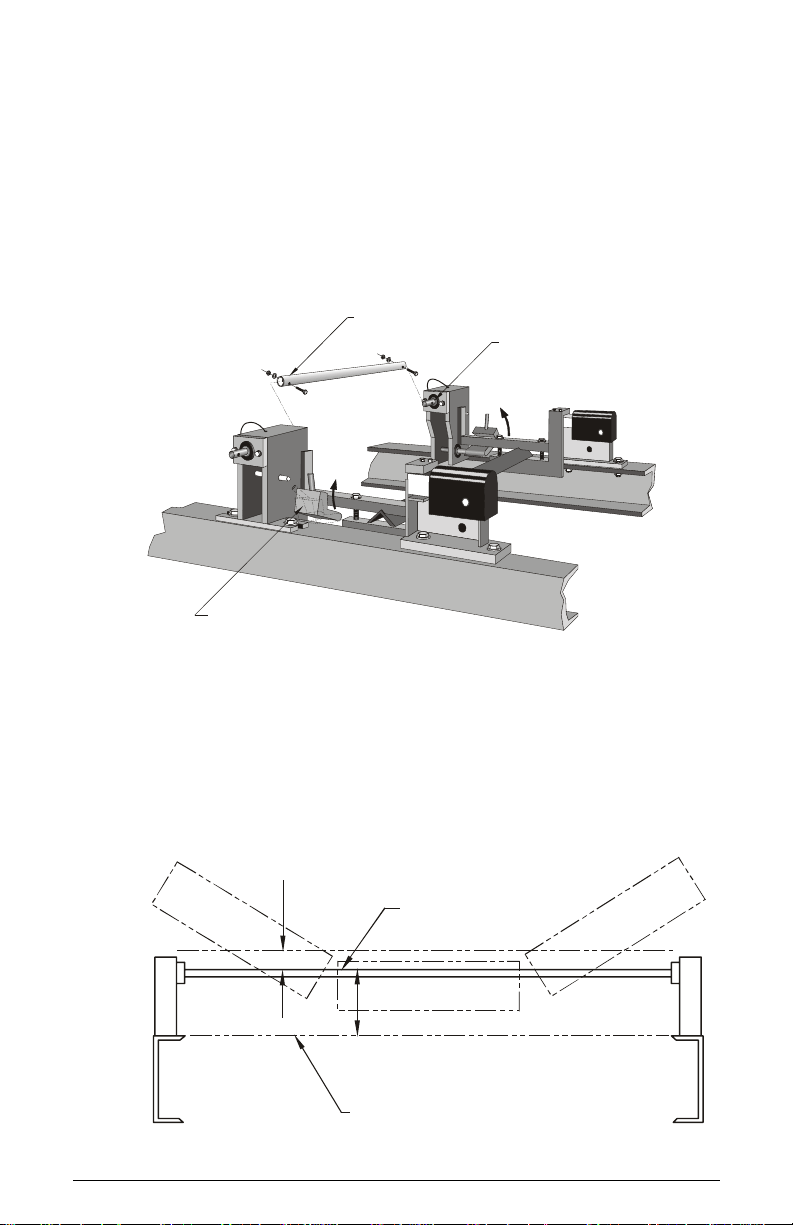
3. Mount torque shaft / Check clearance for conveyor belt
• Leave the locking ball-pins in place to hold the lifting pads of both crank bodies
in the raised position.
• Place the torque tube over the connecting shafts of the left and right crank
bodies.
• Loosely install the bolts, nuts, and washers that hold the torque tube onto the
connecting shafts.
• Hand tighten the bolts, nuts, and washers that mount the crank bodies to the
stringers.
• Hand tighten the bolts, nuts, and washers that hold the torque tube onto the
connecting shafts.
Torq ue Tub e
Connecting shaft (2)
Lifting-pad in raised position (2)
Check Clearance for Conveyor Belt
• Ensure there is 10mm (0.38") minimum clearance from the top of the torque tube
to the underside of the return belt: inadequate clearance will cause the belt to
wear.
• Allow additional clearance for belt sag.
• If necessary, shim the idlers in the scale area until the clearance is adequate.
(See the Belt Scale Instruction Manual for detailed shim procedures.)
Min.10mm (0.38") clearance to underside
of return belt + allowance for belt sag
Top of torque tube
176mm (6.94")
Top of stringers
Page 8 Milltronics Weight Lifter MWL – Instruction Manual 7ML19981CR01
Page 11

4. Install crank handle
• Determine whether it will be more convenient to have the handle attached to the
left-handed or the right-handed crank body, and if the shaft extension is
required.
• Remove the plastic cap from the input shaft on the selected side.
• If the shaft extension is required, slide the female end of the extension over the
exposed input shaft, and secure the extension with a bolt, nut, and washer.
• Slide the female end of the handle over the exposed input shaft (or shaft
extension).
• Secure the handle in place using the tethered locking ball-pin provided.
Locking ball-pin
(tethered to
Crank Body)
(tethered to Crank Handle)
Locking ball-pin
Shaft Extension
Input Shaft
Crank Handle
(female end)
Nut
Hole for storage
on locking ball-pin
Wash er
Bolt
Bolt
7ML19981CR01 Milltronics Weight Lifter MWL – Instruction Manual Page 9
Page 12

5. Test the unloaded MWL / Align crank bodies
• Remove the locking ball-pins from each of the crank bodies. The ball-pin on the
access side will serve as a locking safety pin when the weights are stored.
• Turn the crank handle and watch the lifting pads move up and down.
• Check to see whether any binding occurs during the process. If there is any
binding or hesitation, the crank bodies need to be aligned to each other.
Calibration weight support (2)
Lifting-pads raised
Lifting-pads lowered
Align the crank bodies to each other, if necessary
a. Loosen the two bolts that mount each crank body.
b. Turn the crank handle until the lifting pads have completed at least one
complete cycle from a raised to a lowered position: this process should
automatically align the crank bodies.
c. Retighten the bolts that mount the two crank bodies.
d. Check again, and repeat the process until the MWL operates smoothly, with no
resistance.
Page 10 Milltronics Weight Lifter MWL – Instruction Manual 7ML19981CR01
Page 13

6. Install calibration weights / Check for clearance
Note: Ensure adequate base-bar weight clearance before adding calibration weights.
Base-bar weight
applied
Lifting-pads down
• Turn the crank handle until the lifting pads are fully lowered.
• Place the base-bar weight into position on the calibration-weight supports of
the Milltronics belt scale.
• Ensure there is 10mm (0.38") minimum clearance between the underside of the
base-bar weight and the top of the lowered MWL lifting pads. If necessary, shim
the belt scale and adjacent idlers to achieve this clearance.
Calibration-weight support
Underside of base-bar weight
10mm (0.38") minimum gap
Top surface of lifting-pad
Lifting-pad lowered
7ML19981CR01 Milltronics Weight Lifter MWL – Instruction Manual Page 11
Page 14
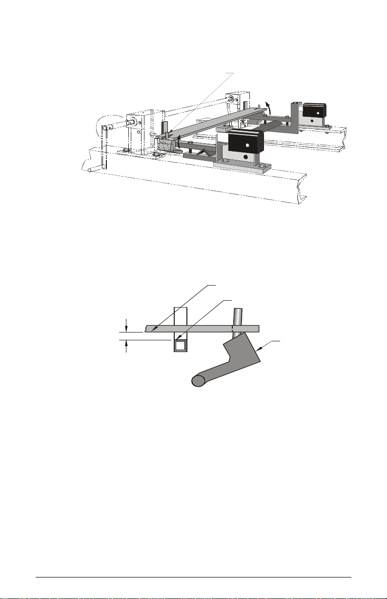
• Gently turn the crank handle until the lifting pads are fully raised: you may need
to guide the notches in the base-bar weight onto the round guide-pin initially.
Round guide pin engages the notch
on the end of the base-bar weight
• Ensure there is 10mm (0.38") minimum clearance between the underside of the
base-bar weight and the top surface of the calibration-weight support when the
lifting pads are fully raised. If necessary, shim the MWL to achieve this
clearance.
Underside of base-bar weight
Top surface of calibration-
weight support
Lifting pad raised
10mm (0.38")
minimum clearance
Page 12 Milltronics Weight Lifter MWL – Instruction Manual 7ML19981CR01
Page 15

• Ensure there is sufficient clearance between the side of the base-bar weight
and the vertical arms of the calibration-weight support arm, or support bracket:
(see dimensions shown below). If necessary, move the two crank bodies further
from the calibration-weight supports to achieve this clearance.
Minimum clearance on MUS Scales: 10mm (0.38")
on MSI Scales: 12.5mm (0.5")
Ver tical a rm
of calibration-weight support
Base-bar weight
• Recheck the crank body alignment: (See “Align the crank bodies to each other, if
necessary” on page 10).
7ML19981CR01 Milltronics Weight Lifter MWL – Instruction Manual Page 13
Page 16

7. Test the loaded MWL
Calibration weights
applied
Calibration-weight support (2)
Lifting pads raised
• Keep the lifting-pads raised, and add the other calibration weights
• Check again to ensure there is 10mm (0.38") minimum clearance between the
side of the stacked weights and the vertical arms of the calibration-weight
supports. If necessary, move the two crank bodies further from the calibrationweight supports to achieve this clearance.
Minimum clearance on MUS scales: 10mm (0.38")
on MSI Scales: 12.5mm (0.5")
Vertical arm of calibrationweight support
Calibration weights
• Recheck the crank body alignment: (See “Align the crank bodies to each other, if
necessary” on page 10)
Page 14 Milltronics Weight Lifter MWL – Instruction Manual 7ML19981CR01
Page 17

8. Shim the MWL (if required) / Recheck base-bar weight for clearance
When the MWL is used with the MUS belt scale, due to the wide variety of idler types
and sizes, it may be necessary to shim the MWL for proper operation.
Note: These tables are provided as a guideline only: shimming is often not required
Shim Tables
Angle Spine:
Angle Size
2" none
2-1/2" 0.31" (8mm) 1
3 " 0.31" (8mm) 2
3-1/2" 0.31" (8mm) 3
4" 0.31" (8mm) 4
• Compare your idler spine to the spine type and size in the tables above, for a
guide to the size of shims you may require.
• Select shims that will allow you to adjust the MWL crank bodies to the correct
level.
• Remove the bolt, nut, and washer on one crank body and position the shim
between the crank body and the conveyor stringer: it should not be necessary to
loosen or remove the torque tube connecting the two crank bodies.
• After the shim is in position, re-install and tighten the bolt, nut, and washer.
• Repeat the same procedure with the other crank body, then recheck the crank
body alignment. (See next page for details.)
Shim
Thickness
Number of
shims
Channel
3" none
4" 0.31" (8mm) 1
5" 0.31" (8mm) 1
6" 0.31" (8mm) 2
Size
Channel Spine:
Shim
Thickness
Number of
shims
Bolt
Shim, if required
Washer
Nut
7ML19981CR01 Milltronics Weight Lifter MWL – Instruction Manual Page 15
Page 18

Recheck crank body alignment
• After shimming, raise and lower the lifting pads to check whether there is any
binding or hesitation. If there is, repeat the alignment procedure on page 10.
• Raise the lifting pads again and check the clearance between the underside of
the base-bar weight and the top surface of the calibration-weight support.
Underside of base-bar weight
Top surface of calibration-
10mm (0.38")
minimum clearance
weight support
Lifting pad raised
• Repeat the shimming procedure until the lifting pads raise the calibration
weights at least 10mm (0.38") above the calibration-weight supports.
• Tighten the torque shaft bolts and the crank-body mounting bolts, then recheck
all clearances.
The MWL installation is now complete.
Page 16 Milltronics Weight Lifter MWL – Instruction Manual 7ML19981CR01
Page 19

Operation
Note: To ensure accurate calibration, you must keep the area between the MWL
lifting pads and the calibration weights clear of buildup during the calibration routine.
(See Maintenance procedures on page 19.)
Applying calibration weights
Simply turn the crank handle until the calibration weights are fully lowered onto the
calibration-weight supports of the belt scale. (Please see the manuals for the Milltronics
Belt Scale and the Integrator, for the appropriate calibration procedures.)
Flat bar calibration
weights applied
Calibration-weight supports (2)
Lifting pads down
Storing calibration weights
After you have completed the scale calibration procedure, turn the crank handle until the
lifting-pads are fully raised.
Crank Handle stored on far side of
Crank Body, with locking ball-pin
Lifting-pads
raised
Storing crank handle
Remove the crank handle and store it. (See next page for details.)
7ML19981CR01 Milltronics Weight Lifter MWL – Instruction Manual Page 17
Page 20

Remove the crank handle and store it, to prevent it from impeding traffic or material when
the conveyor is in operation.
• Remove the locking ball-pin tethered to the crank handle, and remove the handle.
• Use the locking ball-pin tethered to the crank body nearest to the handle to secure
the MWL from unintended use and to store the crank handle.
• Insert the locking ball-pin through the hole in the crank handle, and into the
insertion point in the center of the crank body. Two clips on the side of the crank
body help to hold the handle in position.
• Cover the input shafts with a guard, if they present a hazard to personnel when the
MWL is not in use.
Page 18 Milltronics Weight Lifter MWL – Instruction Manual 7ML19981CR01
Page 21

Maintenance Procedures
Removing material accumulation
To ensure that the belt scale will provide optimal accuracy, periodically inspect the area
around the calibration weights and remove any material build-up.
The calibration weights must remain consistent to calibrate the scale correctly. If material
accumulates on top of them, the added weight will cause the calibration procedure to
produce poor results. The top surface of the calibration-weight supports must also be kept
clean for the scale to produce accurate results.
Material should not accumulate inside the crank body housings under normal operating
conditions, but it is a good idea to inspect them periodically.
Note: Before starting a calibration procedure, be sure to check that there is no
material accumulation in the three areas described below:
1. Top surface of
calibration weights
(Bushed
end-plate)
3. Inside crank body
1. Remove any material build-up from the top of the calibration weights.
2. Remove any material build-up from the top surface of the calibration-weight
supports between the calibration weights and the conveyor scale.
3. Check inside the MWL crank body and inspect the worm gear drive: if material has
accumulated here, remove it with an air stream or other suitable device.
2. Top surface of calibrationweight support
Note: The worm gear and notched plate are normally not accessible to the human
hand: do not force any foreign matter into the area during operation.
Greasing
On both crank bodies, the teeth of the drive plate are greased at the factory. They should
not require further greasing for a number of operations, depending on operating
conditions. Inspect the drive plate periodically, but apply grease only when it is required.
You may need to remove the bushed end-plates temporarily, to gain access to the teeth
and worm gear.
7ML19981CR01 Milltronics Weight Lifter MWL – Instruction Manual Page 19
Page 22

Appendix I: Installation Drawings
MWL Installation Drawing for the MUS-STD
Standard Duty Belt Scale
516mm
(20.30")
14mm (0.56") dia. holes (typ.)
133mm
(5.22")
214mm
(8.43")
Belt Width + 229 mm (9")
or to suit
10mm (0.38") minimum clearance
from vertical arm to weights
Base-bar weight centered
on guide-pin
Belt
Belt Width + 229 mm (9")
Belt
or to suit
Page 20 Milltronics Weight Lifter MWL – Instruction Manual 7ML19981CR01
Page 23

MWL Installation Drawing for the MUS-HD
Heavy Duty Belt Scale
608mm
133mm
(5.22")
246mm
(9.67")
(23.92")
14mm (0.56") dia.
holes (typ.)
Belt width + 229mm (9")
or to suit
10mm (0.38") minimum clearance
from vertical arm to weights
C
Base-bar weight
centered on guide-pin
Belt
Belt
Belt width + 229mm (9")
or to suit
Retrofitting an MUS-HD Heavy Duty Belt Scale:
See next page for details.
7ML19981CR01 Milltronics Weight Lifter MWL – Instruction Manual Page 21
Page 24

Retrofitting an MUS-HD Heavy Duty Belt Scale:
Two new idler clamping brackets are supplied with the MWL. These brackets provide
better clearance for the base-bar weight and the flat bar calibration weights.
• Replace the existing idler clamping brackets with the new idler clamping brackets,
one at a time, re-using the existing bolts, nuts, and washers.
• Tighten the nuts securely while ensuring that the clamping brackets remain parallel
to the run of the conveyor stringers.
Please see the MUS instruction manual for further details.
Page 22 Milltronics Weight Lifter MWL – Instruction Manual 7ML19981CR01
Page 25

MWL Installation Drawing for the MSI or MMI
Belt Scale
14mm (0.56") dia.
holes (typ.)
Belt width + 229mm (9")
or to suit
133mm
(5.22")
265mm
(10.42")
Base-bar weight
centered on guide-pin
Belt width + 229mm (9")
or to suit
Belt
Belt
12.5mm (0.5") minimum clearance
from vertical arm to weights
Retrofitting an MSI or MMI Belt Scale:
Two new calibration-weight brackets are supplied with the MWL to replace the existing
calibration-weight bar. New bolts are supplied, but you will also need a C-clamp, metric
Allen keys, and metric wrenches.
7ML19981CR01 Milltronics Weight Lifter MWL – Instruction Manual Page 23
Page 26

Note: Take care to protect the load cells from impact or prying forces during
installation of the new calibration-weight brackets.
1. Rotate the shipping stops on the MSI into a vertical position, and tighten screws A
to secure the stops in place. This will help to protect the load cells from damage
while the calibration-weight brackets are being installed.
Screws
A
Shipping stop in
free position
Screws
B
Shipping stop in
free position
2. Remove the idler.
Idler removed
Shipping stops in
vertical position
Calibration-weight bar removed
Calibration-weight brackets
Bolts - (step 6)
3. Remove the two socket-head cap-screws that secure the calibration-weight bar,
then remove the calibration-weight bar from the dynamic beam of the belt scale.
Page 24 Milltronics Weight Lifter MWL – Instruction Manual 7ML19981CR01
Page 27

4. Clamp the bottom of the idler support angle-brackets to the dynamic beam, using
two C-clamps.
Angle-bracket
Dynamic beam
C-clamp
Calibration weight
bracket
5. Remove the four socket flat-head bolts that secure the idler support angle-brackets.
6. Mount the new calibration-weight brackets using the same holes as the idler
support angle brackets. Use the new bolts and nuts supplied with the MWL, and
hand-tighten the nuts.
7. Align the new calibration-weight brackets with each other vertically and
horizontally.
8. Tighten the nuts and bolts firmly to secure all four brackets. Torque value = 54.6 Nm
(40 ft-lbs.)
9. Remove the C-clamps.
10. Re-install the idler and check idler alignment as described in the Belt Scale
Instruction Manual.
11. Free the weighing mechanism: loosen screws A and rotate the 2 shipping stops
inward and down, over screws B (See step 1, page 24). Tighten screws A to secure
them in place.
7ML19981CR01 Milltronics Weight Lifter MWL – Instruction Manual Page 25
Page 28

Page 26 Milltronics Weight Lifter MWL – Instruction Manual 7ML19981CR01
Page 29

Appendix II: Customer Calculation Sheet
Calculation of Total Calibration Weight Mass
Record the value of the base bar and weights to be attached. The weights should be
recorded in kilograms or pounds, depending on the units system. In the case of 100mm (4")
flat bar weights, the U-bolts which secure the bars each weigh 0.43 gm. (0.95 lb).
Weight of Base Bar __________________ kg. or lb.
Mass of Calibration Weights ___________________
___________________
___________________
___________________
___________________
___________________
___________________
___________________
___________________
___________________
___________________
___________________
___________________
___________________
___________________
___________________
___________________
___________________
___________________
Grand Total ___________________ kg. or lb.
Calculation of Load Reference Values
Calibration Reference Value in kilograms/metre = Grand Total in kg
Idler Spacing in m
Or
Calibration Reference Value in lb/foot = Grand Total in pounds
Idler Spacing in feet
7ML19981CR01 Milltronics Weight Lifter MWL – Instruction Manual Page 27
Page 30

Using the Factoring Function of the Belt Scale Integrator
If the belt scale system has been pre-calibrated, as in the case of an MWL retrofit, the belt
scale system should be zeroed. The Factor function of the Integrator should be used to
accurately determine the value of the calibration weights in terms of the existing span
calibration. (See the Integrator manual for more detail.)
Page 28 Milltronics Weight Lifter MWL – Instruction Manual 7ML19981CR01
Page 31

*7ML19981CR01*
 Loading...