

Page 1

MULTIRANGER
PLUS
PROGRAMMABLE
LEVEL SYSTEM
Instruction Manual
PL-443
June 1995
33454430
PRR 1.1
Page 2

Page 3

Table of Contents
General Information
Important 1 - 1
MultiRanger Plus 1 - 1
Specifications
MultiRanger Plus 2 - 1
Programmer 2 - 2
Transducer 2 - 2
Temperature Sensor 2 - 2
Current Output Isolator 2 - 2
Cabling 2 - 2
Installation
Multiranger Plus 3 - 1
Outline and Mounting 3 - 1
Circuit Board Layout 3 - 2
Interconnection 3 - 3
Installing the Transducer 3 - 3
Selecting Temperature Source 3 - 4
Current Output 3 - 4
Current Output Isolator 3 - 5
Synchronization 3 - 6
Power Connections 3 - 7
Programmer 3 - 8
Start Up
General 4 - 1
Programmer Keypad Run Mode 4 - 2
Legend 4 - 4
Parameter Entry 4 - 4
Common Display Messages 4 - 6
PL-443 i
Program Mode 4 - 3
Page 4

Functional
Transceiver 5 - 1
Damping and Process Rate 5 - 1
Temperature Compensation 5 - 2
Sound Velocity 5 - 2
Blanking 5 - 3
Agitator Discrimination 5 - 4
Relays General 5 - 4
Function
Alarm 5 - 5
Pump 5 - 6
Miscellaneous 5 - 7
Analog Output 5 - 10
Applications 6 - 1
Simple Level Application 6 - 2
Pump Control Applications 6 - 4
Pump Run-On 6 - 8
Pump Totalizer Application 6 - 10
Volume Application 6 - 14
Common Tank Shapes 6 - 15
Custom Design Tanks 6 - 16
Compensation 6 - 19
Differential Level Application 6 - 22
OCM Applications 6 - 26
Single Exponential 6 - 33
Palmer-Bowlus 6 - 37
H Flumes 6 - 38
Other 6 - 39
Applications with Standpipes 6 - 42
PL-443 ii
Page 5

Parameter Description
Parameters 7 - 1
Troubleshooting
General 8 - 1
Oscilloscope 8 - 1
Troubleshooting Guide 8 - 3
Maintenance
Maintenance 9 - 1
Appendices
Sound Velocities 10 - 1
Glossary 10 - 2
Alphabetical Parameter Listing 10 - 4
PL-443 iii
■
Page 6

Page 7

GENERAL INFORMATION
IMPORTANT
First and foremost it is essential that this manual be read and understood before
installation and start up of the MultiRanger Plus.
"Applications" provides a general description of the common applications found in
industry and illustrates them with examples. It is suggested that you refer to the
sub-section which most suits your application. The programming of the MultiRanger
Plus can be optimized by referring to Parameter Description or Appendices \
Alphabetical Parameter Listing.
THE MULTIRANGER PLUS
The MultiRanger Plus is a multi-purpose level monitoring system consisting
of a MultiRanger Plus in a CSA type 4 enclosure, a programmer and an
ultrasonic transducer.
The MultiRanger Plus emits an ultrasonic pulse via the transducer. The echo is
reflected from the material and received by the transducer. The echo is processed by
the MultiRanger Plus and the time at which the ultrasonic pulse hits the level or target
is extracted and compared to the time at which it was sent. The time differential is
then converted into distance, material level, volume, flow or differential level as a
basis for display, relay control, analog output and totalling.
As well as simple level measurement, the MultiRanger Plus was designed to handle
specific applications such as: pumped volume totalling, differential level and open
channel flow measurement.
PL-443 1 – 1
■
Page 8

Page 9

SPECIFICATIONS
MULTIRANGER PLUS
Power: » 100/115/200/230 V ±15%, stab selective
» 50/60 Hz, 15 VA
» optional: » 12 V dc model, 10 to 18 V dc
Fuse: » 1/4 amp MDL Slo-Blo or equivalent
Range: » 0.3 to 15 m (1 to 50 ft)
Accuracy: » 0.25% of range or 6 mm (0.24"), whichever is greater
Resolution: » 0.1% of range or 2 mm (0.08"), whichever is greater
Memory: » EEPROM (non-volatile) no back-up battery required
Display: » Liquid Crystal Display of 4 digits, 18mm (0.7") high
Operating Temperature: » – 20 to 60 °C (– 5 to 140 °F)
Outputs: transducer drive: » 41 KHz, 400 V peak pulses of 1 msec
max duration at a max
repetition rate of 300 msec
analog: » 0 - 20 or 4 - 20 mA
» max loading: » 350 ohms, return to ground
» 24 V dc model, 18 to 36 V dc
» 750 ohms, return to –12 V
» resolution: 0.1% of range
» optional mA isolator
relays: » 5 multipurpose relays (for alarms, pump control,...)
» 1 Form "C" SPDT contact per relay, rated 5 A at
220 V ac non-inductive
» adjustable deadband
All relays are certified for use in equipment where the short
circuit capacity of the circuits in which they are connected is
limited by fuses having ratings not exceeding the rating of the relays.
Enclosure: » CSA enclosure type 4 (similar to NEMA 4)
» 160 mm W x 250 mm H x 82 mm D
(6.3" W x 9.5"H x 3.2"D)
» polycarbonate
Approvals: » CE
Weight » 1.8 kg (4lb)
PL-443 2 – 1
96/01/22
Page 10

PROGRAMMER
Enclosure: » general purpose
Operating Temperature: » – 20 to 50 °C (– 5 to 122 °F)
Power: » 9 V battery (style - ANSI/NEDA 1604)
» 67 mm W x 100 mm H x 25mm D
(2.6" W x 4" H x 1" D)
» ABS plastic
TRANSDUCER
Refer to associated Transducer manual.
TEMPERATURE SENSOR
Refer to associated Temperature Sensor manual
CURRENT OUTPUT ISOLATOR (Optional, refer to PL-293)
Model: » LIs-1 loop isolator
Input: » 4 - 20 mA dc (from MultiRanger Plus)
Output: » 4 - 20 mA dc into 600 ohm max
Isolation: » 300 V ac continuous
Common Mode Rejection » 100 dB at 60Hz
CABLING
Optional: » RG-62A/U coax
» max distance to electronics: 365 m (1200 ft)
» must be run in grounded metal conduit
Temperature Sensor: » Belden 8760, 2 wire shielded
» max distance to electronics: 365 m (1200 ft)
» can be run with transducer cable
PL-443 2 – 2
■
Page 11
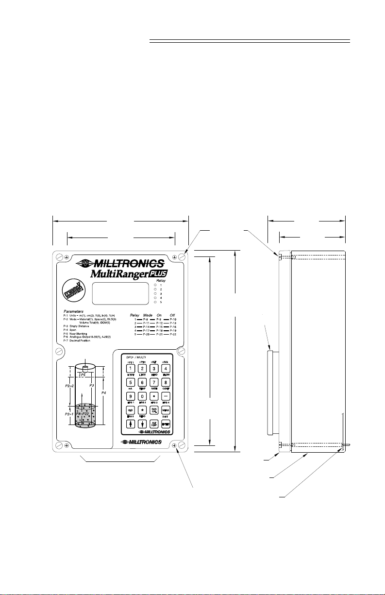
INSTALLATION
97 mm
(3.8")
82 mm
(3.2")
MULTIRANGER PLUS
The MultiRanger Plus should be mounted in an area that is within the unit’s ambient
temperature range, and is suitable for CSA type 4 enclosures and polycarbonate
material. The front cover should be accessible for programming and viewing.
It is advisable to keep the MultiRanger Plus away from high voltage or current runs,
contactors and SCR control drives.
Do not mount the multiranger plus in direct sunlight
without the use of a sun shield.
OUTLINE AND MOUNTING
160 mm
(6.3")
131 mm
(5.1")
228 mm
(9")
lid screws
(6 places)
240 mm
(9.5")
programmer
suitable location for conduit entrances
mounting holes
(accessed under lid
4.3 mm (0.17") dia.
4 places
Milltronics recommends using a punch for making holes in enclosure.
PL-443 3 – 1
lid, clear
polycarbonate
enclosure, CSA
enclosure 4 polycarbonate
customer mounting
screw
Page 12
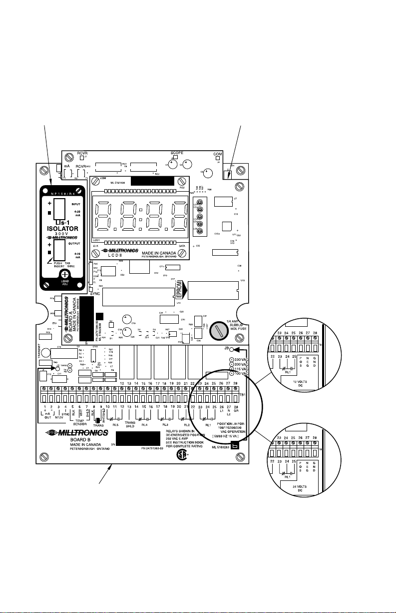
CIRCUIT BOARD LAYOUT
18 to 36 V dc operation
24 V dc model
optional isolator
daughter board
10 to 18 V dc operation
12 V dc model
motherboard
PL-443 3 – 2
Page 13
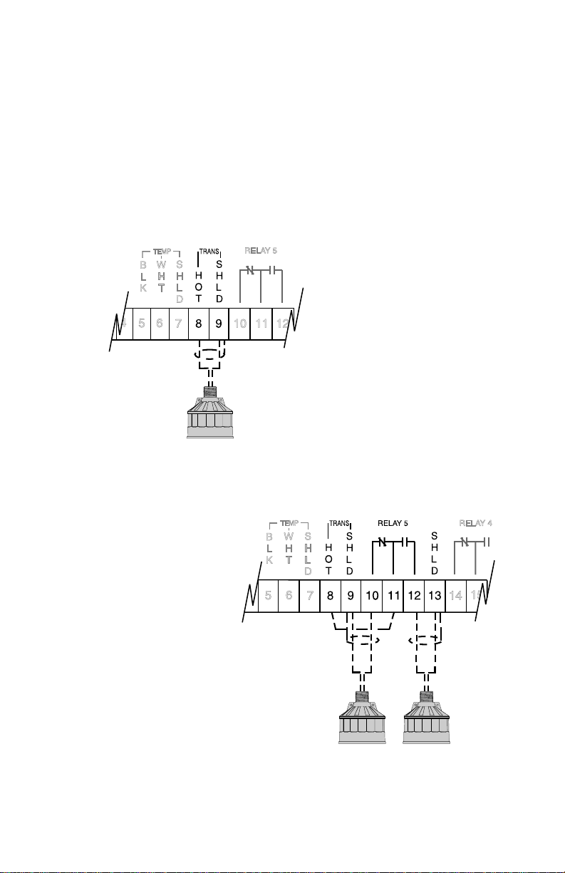
INTERCONNECTION
transducer
#2
All wiring must be done in conjunction with approved conduit,
boxes and fittings and to procedures in accordance
with all governing regulations.
Note :
— — — — indicates customer wiring in all diagrams.
INSTALLING THE TRANSDUCER
Basic Wiring
black
white /
shield
Differential Level - Basic Wiring
refer to transducer manual
for wiring details
PL-443 3 – 3
white /
shield
transducer
#1
black
white /
shield
Page 14
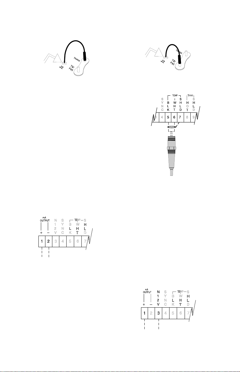
SELECTING TEMPERATURE SOURCE
mA Output - FLOATING
(additional to basic wiring)
board ‘B’
Integral Sensor (transducer)
board ‘B’
CURRENT OUTPUT
mA Output - GROUNDED
(additional to basic wiring)
Note : TB1-2 is internally
connected to electrical
ground TB1-28.
TS-3 or Program
to customer’s equipment
maximum loading 350 Ω
PL-443 3 – 4
mA output wiring into floating input ONLY.
750 Ω max. Do Not Ground!
Page 15
CURRENT OUTPUT ISOLATOR
TB1
If the isolator has not been factory installed, mount it on the upper left hand corner of
the motherboard using the two long machine screws provided. The input terminals of
the isolator are then connected to the motherboard output terminals,TB-1, using
twisted pair maximum 16 gauge wire.
Proper shielding and grounding are required in order to minimize noise levels that
could otherwise affect weak receiver signals by introducing false echoes.
The isolator enclosure is grounded by the mounting bolts to the motherboard. This
can be checked with an ohmmeter if a poor connection is suspected.
The isolator output wiring must be a shielded twisted pair. The shield must be
intact up to the isolator and the shield grounded at the isolator mounting screw
only. Do not ground shield at any other point as this will void isolation.
mA Output - Optional Isolation
(additional to basic wiring)
Customer Wired
Keep shield intact up to output terminals.
Ground shield at screw ONLY!
optional
LIs-1
isolator
Route output wiring
cable in separate
conduit, entering
enclosure as near as
possible to isolator.
Keep wiring as short
as possible. Do not
route cable along
terminal board.
isolated 4 - 20 mA output wiring into 600 Ω max
Factory Wired
optional
LIs-1
isolator
isolated 4 - 20 mA output wiring into 600 Ω max
PL-443 3 – 5
TB1
Page 16
SYNCHRONIZATION
to next MultiRanger Plus
to next MultiRanger
TB1-9 or next
MultiRanger Plus
TB1-4
In applications where more than one MultiRanger Plus, up to a maximum of 8, are
going to be used or where their transducers will be sharing a common conduit,
synchronization is required. When synchronized, no MultiRanger Plus(s) will transmit
within 180 msec of the prior one(s).
To synchronize MultiRanger Plus’s, interconnect the SYNC terminals TB1-4 of all
motherboards and ensure that there is a common hydro ground interconnecting
all units.
To synchronize MultiRanger Plus’s and MultiRangers, interconnect the SYNC terminal
TB1-4 of the MultiRanger Plus to the SYNC terminal TB1-9 of the MultiRanger.
To synchronize more than 8 MultiRangers or MultiRangers with other Milltronics
ultrasonic level detection models (e.g. MicroRanger, AirRanger, etc...) consult
Milltronics or your distributor.
Synchronization of 2 to 8 MultiRanger Plus’s
(additional to basic wiring)
MultiRanger Plus #1
Synchronization of 2 to 8 MultiRanger / MultiRanger Plus’s
MulitRanger Plus
(additional to basic wiring)
All units to be synchronized must be
PL-443 3 – 6
interconnected by a common hydro ground.
MultiRanger Plus #2
MultiRanger
Page 17
POWER CONNECTIONS
18 to 36 V dc
ac Volage Selection
The MultiRanger Plus accepts 100, 115,
200 or 230 V ac per jumper ‘J9’ (board B)
selection or 10 to 36 V dc.
ac Power
select voltage via J9
on board B
12 V dc Model
10 to 18 V dc
24 V dc Model
PL-443 3 – 7
Page 18
PROGRAMMER
In order to program the MultiRanger Plus, a programmer ( which has a magnetic back
plate ) must be placed into the front cover recess on the MultiRanger Plus. Be sure to
keep it away from objects such as floppy disks that are susceptible to damage from
magnetic fields.
A programmer need not be ordered with each unit.
Check your order if you think that the programmer is missing.
PL-443 3 – 8
■
Page 19

START UP
GENERAL
The MultiRanger Plus has two modes of operation: Run and Program (Cal). When
the unit is powered up, after installation procedures have been completed, it is factory
set to start up in the run mode, to detect the distance from the transducer face to the
target in meters. This is the normal mode of operation, which can be programmed to
display level, volume, totals or flow readings and yield corresponding mA output and
relay closures for alarms, pump controls, etc.
The program mode is selected by pressing the
the user to program the MultiRanger Plus to suit his preference and to the particular
application to which the MultiRanger Plus is being applied.
The first step when programming is to reset all parameters to their
After having entered all required parameters, the MultiRanger Plus can be made to
simulate its operation within the particular application giving display, relay operation
and analog output. Refer to parameters P-76 through P-78.
When programming has been completed, the MultiRanger Plus can be put into normal
operation by pressing the
factory setting by using the master reset P-99
Run/Cal
key.
Run/Cal
key. This mode will enable
PL-443 4 – 1
Page 20

PROGRAMMER KEYPAD
All entries are made via the programmer keypad.
Run Mode
Press the associated key to view.
H TOT • high total; P-2 = 4 or 5 (P-55)
L TOT • low total; P-2 = 4 or 5 (P-54)
HEAD head reading, P-2 = 5
FLOW flow rate, P-2 = 5
mA mA output
TEMP temperature (P-65)
RATE rate of level change (P-70)
CONF echo confidence (P-80)
HRS 1 pump 1 service hours (P-24)
HRS 2 pump 2 service hours (P-25)
HRS 3 pump 3 service hours (P-26)
HRS 4 pump 4 service hours (P-27)
HRS 5 pump 5 service hours (P-28)
• PT 1; press to view level at DLD
transducer #1 P-2 = 3
• PT 2; press to view level at DLD
transducer #2, P-2 = 3
PL-443 4 – 2
READ reading (P-76)
RUN initiates access into
CAL program mode
DIST press to view distance (P-78)
Page 21
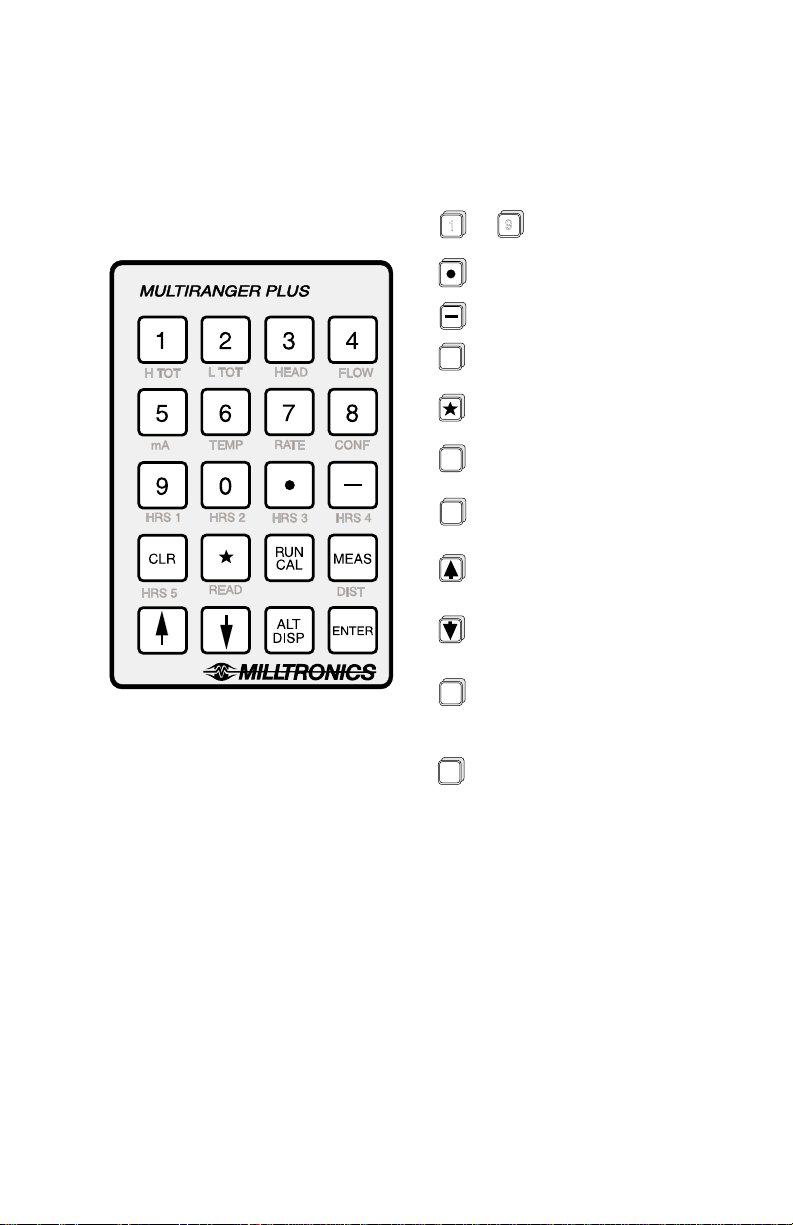
Program Mode
1
CLR
RUN
CAL
MEAS
ALT
DISP
9
to
numeric entry
decimal point entry
negative entry
clear display
completes access
into program mode
enter run mode
press to make
a measurement
increments display to
show the next parameter
decrements display to
show the preceeding parameter
alternates display to show either
the parameter number or
parameter value
PL-443 4 – 3
enters display as contents of
ENTER
selected parameter
Page 22

LEGEND
Press the associated key on programmer:
Display shown on MultiRanger Plus:
Display appears for a short time:
Programmer key:
ENTER
PARAMETER ENTRY
Initial start up
All entries are made via the programmer keypad. All programmers are
interchangeable, thus any programmer can be used in conjunction with any
MultiRanger Plus.
Apply power to the MultiRanger Plus and place the programmer in its front
cover recess. will be momentarily displayed and then a distance reading
e.g. will appear. This is a space or distance reading of up to
approximately 12 m.
If is alternately displayed, an open or short circuited transducer
connection is being indicated.
If is displayed rather than a continuous numeric reading the actual material
distance may be beyond 12 m. Proceed with the programming and if
persists, consult Troubleshooting guide.
To enter Program mode
RUN
CAL
The user may now program the MultiRanger Plus starting at parameter P-1.
To direct access a parameter:
The display should have a ‘ P- ’ and the number of the currently selected parameter.
Current parameter selection
Select desired parameter.
2 0
??
e.g. select
parameter P-20
PL-443 4 – 4
Page 23
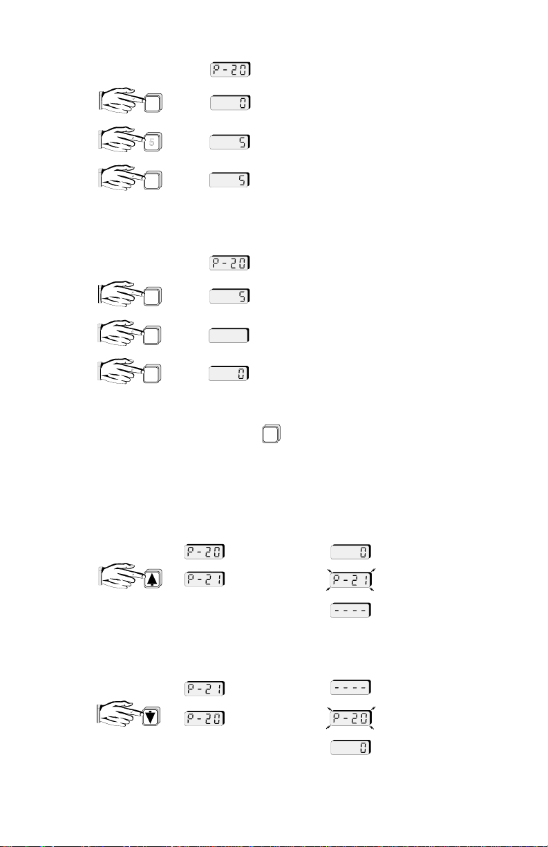
To set a parameter:
scroll ahead to P-21
e.g. value of P-21
access desired parameter e.g. P-20
ENTER
ALT
DISP
5
display parameter value e.g. 0
select new option e.g. 5
new value is entered and displayed e.g. 5
To reset a parameter to its factory value:
e.g. reset P-20
ENTER
ALT
DISP
CLR
display parameter value
display will go blank
factory setting of parameter is entered
and displayed
After a minute and a half, the content display will revert to the parameter number if
the keypad is not used further. Press again if it is desired to return to a display
of the content.
ALT
DISP
To access the next parameter:
To access the previous parameter:
PL-443 4 – 5
parameter number
displayed
parameter content
displayed
e.g. value of P-20
value of P-21
scroll back to P-20
value of P-20
Page 24

COMMON DISPLAY MESSAGES
cable loss of echo » messages CAbL and LOE will alternately
have entered » appears after pressing
program mode "RUN/CAL" key
clear all parameters » P-99
- return factory setting
overflow » reading is larger than display capabilities
loss of echo » displayed in run mode to indicate
percent » appears when programming units of
parameter number » indicates which parameter is
flash, indicating open or short circuited
transducer connection
loss of echo
measurement in percent
being displayed
have entered » appears after pressing
run mode "RUN/CAL" key
no value » contents of parameter empty or
invalid request » application does not yield requested
PL-443 4 – 6
no reading display
reading option or spare parameter
■
Page 25

FUNCTIONAL
TRANSCEIVER
The MultiRanger Plus transceiver will transmit via the transducer, a set of long and/or
short pulses per measurement. The number and duration of the pulses is dependent
upon P-88.
A short pulse has a maximum measurement range of 2 m (6.6 ft) from the transducer
face.
A long pulse has a measurement range of 2 m (6.6 ft) from the transducer face out to
its maximum setting (P-3, empty distance to transducer plus P-87, range extension).
DAMPING AND PROCESS RATE
The MultiRanger Plus provides damping to control the maximum rate of change of the
displayed material level, volume or flow rate and of the mA output signal. As most
relay functions respond to the dampened level reading, they indirectly fall under the
control of the damping function. Damping may be set within the range of 0.001 to
9999 in units selected per minute (eg. if P-1 = 3 and P-68 = 15, then the fill damping
rate is 15 ft/min). P-68 is set to provide damping specifically for filling conditions while
P-69 is set to provide damping specifically for emptying conditions.
The required damping may be estimated by filling and emptying the vessel at its
normal rate. The rate of material level change can be viewed via the process rate
display parameter, P-70 or by pressing "7" while in the run mode. The value of P-68
and P-69 should be equal to or greater than the rates of level change encountered in
P-70. The process rate averaging parameter P-71 selects the method of averaging
used to determine the process rate display, however it has no bearing on the
damping function.
Damping is often used to slow down the rate of response of the display especially
where liquid surfaces are in agitation or material falls into the sound path during filling.
When in the program mode, the damping is automatically overridden to give fast
response when "MEAS" is pressed. In the run mode, the response can be further
increased by turning the fuzz filter (P-72) and agitator discriminator (P-73) off
- ONLY if they are not required.
If the transducer aiming is being adjusted while in the run mode, it is suggested that
damping be at its factory setting of 10 to start. The damping can later be changed to
suit prevailing conditions.
Upon a loss of echo condition and after the fail-safe timer (P-75) expires, the display
will go to fail-safe high at the fill damping rate if P-74 = 1 or to fail-safe low at the
empty damping rate if P-74 = 2.
PL-443 5 – 1
Page 26

TEMPERATURE COMPENSATION
In order to provide compensation for uniform temperature variances of the sound
medium, temperature compensation is provided. Temperature compensation consists
of on board circuitry in the MultiRanger Plus and the integal (transducer) temperature
sensor. The integral temperature sensor uses the transducer’s wiring and input
terminals (TB1 - 8/9) to interface with the on board circuitry. Note: board ‘B’ jumper
‘J2’ must be set to ‘TRANS’.
Optionally, the alternate TS-3 Temperature Sensor can be used to provide a
temperature input, rather than by using the integral temperature sensor.
In order to do this:
» set board ‘B’ jumper ‘J2’ to ‘TS / P65’
» optional TS-3 Temperature Sensor must be connected to TB1 - 5/6/7
If the temperature of the sound medium is to remain constant, compensation may be
programmed into the MultiRanger Plus instead of using the remote sensor input by
one of the following methods:
1. » set board ‘B’ jumper ‘J2’ to ‘TS / P65’
» insure that the temperature sensor input TB1 - 5/6 is left open/unconnected
» select P-65
» enter temperature in °C
2 » set board ‘B’ jumper ‘J2’ to ‘TS / P65’
» insure that the temperature sensor input TB1 - 5/6 is left open/unconnected
- select P-61
- perform an empty calibration
The following temperature functions (in °C) can be viewed:
P-65 air temperature » present temperature at sensor
or
» programmed temperature, if sensor not used
P-66 max. air temperature » highest temperature encountered during operation
P-67 min. air temperture » lowest temperature encountered during operation
SOUND VELOCITY
The MultiRanger Plus can be calibrated for transducer operation in homogeneous
vapours with sound velocities other than that of air.
The basis is to physically measure the level (measuring tape or sight glass) and enter
this value via P-61. The MultiRanger Plus then calculates the sound velocity by
comparing the entered physical measurement to its own ultrasonic measurement
(empty calibration, P-61)
PL-443 5 – 2
Page 27
P-63, velocity at 20 °C can be used to enter the known velocity at 20 °C of sound in a
far end
blanking
range extension (P-87)
as % P-3
particular gas or vapour to view the resultant velocity of a sound velocity
compensation, normalized to 20 °C.
P-64, velocity at P-65, can be used to enter the known velocity of sound in a particular
gas or vapour, or to view the resultant velocity of a sound velocity compensation, at
the temperature of P-65.
Refer to Appendices/Sound Velocities, for typical sound velocities in various gases
and vapours.
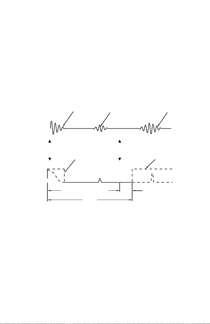
BLANKING
Near blanking (P-5) is used to ignore the zone in front of the transducer where ringing
or other false echo is at a level with the processing of the true echo.
ringing
typical receiver signal
true echo
(level)
false echo
Ringing is the inherent nature of the transducer mass to continue vibrating after the
transmit pulse has ceased. The amount of ringing varies with the type of transducer
used and decays to acceptable levels in the order of milliseconds. Excessive cold and
overtightening of the transducer mounting will increase the ring time such that it may
appear as an echo during the receive cycle. This is usually indicated by an incorrect
high level reading. This condition may be verified with the use of an oscilloscope and
may be overcome by increasing the near blanking (refer to Troubleshooting).
Far end blanking is a design function that ignores the zone below the zero or empty
level where false echoes may appear at levels that interfere with the processing of
true echo.
In applications where the zero level is above the bottom of the vessel and it is desired
to monitor the zone below the normal zero, range extension (P-87) may be used to
extend the range into the far end blanking. Range extension is entered as a percent of
P-3. As range extension reduces the protection afforded by the far end blanking, it
should be used judiciously. Avoid excessive range extension as this may reduce the
PL-443 5 – 3
end of
transmit
P-5
near blanking
empty distance to transducer
P-3
range
typical processed signal
0
level
Page 28

measurement’s reliability and accuracy. If it is found that false echoes are appearing
ahead of the blanking zone, P-87 should be reduced accordingly.
Blanking is automatically corrected for sound velocity change where temperature
and velocity compensation is used, keeping the blanking at the distance at which it
was entered.
AGITATOR DISCRIMINATION
In applications where there is an agitator operating in the vessel, the blades may
interfere with level readings when the material level is lower than the blades. In such a
case, the agitator discriminator (P-73) can be turned on (factory setting).
With the agitator turned on, the reading will not change unless the echo is closer for at
least 5 consecutive measurements nor will it change unless the echo is farther for at
least 2 consecutive measurements.
This feature allows the MultiRanger Plus to remain locked on the true echo, even if
there are occasional false echoes due to the agitator blades, electrical noise or
crosstalk from other ultrasonic units.
Agitator discrimination, however, slows down the MultiRanger Plus’s speed of
response. Therefore, if fast response is required, especially when aiming the
transducer while in the run mode, and there is no agitator involved, the discriminator
should be turned off.
Agitator discrimination will not work if the blades are
stationary and in the transducer’s beam path.
RELAYS
General
Five onboard multi-purpose relays are provided on the MultiRanger Plus. Each relay
may be independently assigned to one function and has a corresponding status LED,
visible through the front cover.
The relay functions fall under three modes of operation :
» alarm : alarm ON = LED ON = relay coil de-energized
» pump : pump ON = LED ON = relay coil energized
» miscellaneous : contact closed = LED ON = relay coil energized
Complete programming of each relay requires two steps. Refer to the Relay
Programming Chart Relays.
1 - select a relay function
2 - enter relay ON/OFF setpoints for function options 1-6 and 8-10.
OR
- set control parameters for function options 7,11,12,13 and 14.
PL-443 5 – 4
Page 29

Function
Alarm
level : - in high alarm, the function goes on when the level rises
in bounds : - the relay will be in alarm if the level is inside the zone
out of bounds : - the relay will be in alarm if the level is outside the
differential : - the high alarm function goes on when differential
rate of change : - in filling alarm, the function goes on when the rate of filling
to the ON setpoint and goes off when the level lowers to
the OFF setpoint. In low alarm, the function goes on
when the level lowers to the ON setpoint and goes off
when the level rises to the OFF setpoint.
between the setpoints.
zone between the setpoints.
level increases to the ON setpoint and goes off when the
differential level decreases to OFF setpoint. The low alarm
function goes on when the differential level decreases
to the ON setpoint and goes off when the differential level
increases to the OFF setpoint.
increases to the ON setpoint and goes off when the rate of filling
drops to the OFF setpoint. In emptying alarm, the function goes
on when the rate of emptying increases to the ON setpoint and
goes OFF when the rate of emptying drops to the OFF setpoint.
For emptying alarm, the setpoints must be entered as
negative values.
temperature : - in high alarm, the function goes on when the temperature rises to
loss of echo : - the function goes on when the fail-safe timer expires. The function
PL-443 5 – 5
the ON setpoint and goes off when the temperature lowers to the
OFF setpoint. In low alarm, the function goes on when the
temperature lowers to the ON setpoint and goes off when the
temperature rises to the OFF setpoint.
goes OFF when a valid echo is received (fail-safe timer is reset).
Page 30

Pump
level : - in pump down, the function goes on when the level rises
sequential : - refer to Applications\Pump Control. Select function option 8, 9 or 10
differential : - the pump down function goes on when differential
to the ON setpoint and goes off when the level lowers to the
OFF setpoint. In pump up, the function goes on when
the level lowers to the ON setpoint and goes off when the
level rises to the OFF setpoint.
and press "*" to scroll through the loss of echo defaults.
For option 9, pressing "*" will also scroll through the cumulative,
ratio or duty/back-up mode of pump up operation.
level increases to the ON setpoint and goes off when the
differential level decreases to OFF setpoint. The pump up
function goes on when the differential level decreases
to the ON setpoint and goes off when the differential level
increases to the OFF setpoint.
LCD display
loss of echo default
En = energized, pump ON after P-75 expires
dE = de-energized, pump OFF after P-75 expires
Ho - hold prior relay status after P-75 expires
:
sequential loop. optional to function 9
blank = cumulative
’ = duty/back-up
A = ratio
function
8 = level, fixed roster
9 = level, sequential
10 = differential
e.g. dE : ’9 = duty/back up sequential pumping
PL-443 5 – 6
de-energize under loss of echo
Page 31

Miscellaneous
totalizer and samplers : - refer to Application Pump Totalizer and OCM . Relays
scanner : - this function is specific to relay 5 and the DLD mode of operation.
The transducer hot is wired to the common terminal of the relay
so that when switched, the transceiver may alternately access
transducer #1and #2.
Refer to Applications \ Differential Level Application.
Setpoint - ON / OFF
If the ON setpoint is higher than the OFF setpoint, the relay operates as :
» high alarm
» pump down control
» high differential alarm
If the ON setpoint is lower than the OFF setpoint, the relay operates as :
» low alarm
» pump up control
» low differential alarm
The ON and OFF setpoints can not be the same on an individual relay but may be
common to other relays. The dead band or hysteresis is the difference between the
ON and OFF setpoints. For in and out of bounds level alarms, the hysteresis is set
±2 % of span from either boundary.
are normally de-energized, contact closure is
approximately 200 mSec duration.
The setpoints for alarm functions 1 - 4 and pump functions 8 - 10 are always entered
in the P-1 units of measurement selected (but not %). The setpoints are measured
from the bottom up, referenced to zero or empty except for the differential functions,
4 and 10. There the setpoints represent the absolute differential between levels,
regardless of the level with respect to zero.
Relay status - non run modes
When the fail-safe timer expires, pump control relays respond as previously
described. However, alarm relays will respond in the following manner.
FAIL-SAFE MODE RELAY STATUS
P-74 high alarm low alarm
fail-safe high on off
fail-safe low off on
fail-safe hold hold hold
Upon entering the program mode, all pump control relays will be turned OFF. Alarm
relays will hold their prior status, but will respond to measurements take when "MEAS"
is pressed.
PL-443 5 – 7
Page 32

Simulation
Parameters P-76 through P-78 can be used to simulate relay operation in the program
mode. Pump relays will be held OFF during simulation, however their corresponding
LED’s will respond. Remote totalizer and flow sampler relay operation do not apply to
simulation. Refer to Parameter Description.
If the relay status can affect plant operation or personnel safety,
it is advisable to override the relay functions or disconnect the relay
Relay Function Vs Mode of Operation
It should be noted that some relay functions can not be used in certain modes
of operation. The following table shows the valid functions for the five modes
of operation.
Function Mode of Operation
0 off off off off off
1 level level level level level
2 in bounds in bounds off in bounds in bounds
3 out of
4 off off differential
5 rate rate off rate rate
6 temp. temp. temp. temp. temp.
7 L.O.E. L.O.E. L.O.E. L.O.E. L.O.E.
8 pump pump pump pump pump
9 sequential sequential off sequential sequential
10 off off pump on
11 off off off totalizer totalizer
12 off off off flow
13 time
14 off off scanner off off
wiring during calibration or simulation
Keep power disconnected at main breaker
when MultiRanger Plus cover is opened.
Mat’l Space DLD Pump Vol. OCM
(P2 = 1) (P2 = 2) (P2 = 3) (P2 = 4) (P2 = 5)
bounds
sampler
out of
bounds
time
sampler
off out of
level
differential
time
sampler
bounds
off off
off off
sampler
time
sampler
out of
bounds
flow
sampler
time
sampler
PL-443 5 – 8
Page 33

RELAY PROGRAM CHART
Relay 1 Relay 2 Relay 3 Relay 4 Relay 5
Relay Function
Alarm : Level 1 P-9 P-10 1 P-12 P-13 1 P-15 P-16 1 P-18 P-19 1 P-20 P-21 P-1
In bounds 2 " " 2 " " 2 " " 2 " " 2 " " "
Out of bounds 3 " " 3 " " 3 " " 3 " " 3 " " "
Differential 4 " " 4 " " 4 " " 4 " " 4 " " "
Rate of Change 5 " " 5 " " 5 " " 5 " " 5 " " P-1/min
Temperature 6 " " 6 " " 6 " " 6 " " 6 " " ° C
Loss of Echo 7 set P-75 7 set P-75 7 set P-75 7 set P-75 7 set P-75 n/a
Pump : LevelEn: 8* P-9 P-10 8* P-12 P-13 8* P-15 P-16 8* P-18 P-19 8* P-21 P-22 P-1
Sequential En: 9* " " 9* " " 9* " " 9* " " 9* " " "
cumulative
duty / backup
ratio
Differential En: 10* " " 10* " " 10* " " 10* " " 10* " " "
Miscellaneous :
Totalizer 11 set P-56 11 set P-56 11 set P-56 11 set P-56 11 set P-56 vol.P-43
Flow Sampler 12 set P-57 &
Time Sampler 13 set P-59 13 set P-59 13 set P-59 13 set P-59 13 set P-59 hr
Scanner n/a n/a n/a n/a n/a n/a n/a n/a 14 set P-2 n/a
Fctn
P-8
dE: 8* " " 8* " " 8* " " 8* " " 8* " " "
Ho: 8* " " 8* " " 8* " " 8* " " 8* " " "
dE: 9* " " 9* " " 9* " " 9* " " 9* " " "
Ho: 9* " " 9* " " 9* " " 9* " " 9* " " "
En:’ 9* " " 9* " " 9* " " 9* " " 9* " " "
dE:’ 9* " " 9* " " 9* " " 9* " " 9* " " "
Ho:’ 9* " " 9* " " 9* " " 9* " " 9* " " "
En:A 9* " " 9* " " 9* " " 9* " " 9* " " "
dE:A 9* " " 9* " " 9* " " 9* " " 9* " " "
Ho:A 9* " " 9* " " 9* " " 9* " " 9* " " "
dE: 10* " " 10* " " 10* " " 10* " " 10* " " "
Ho: 10* " " 10* " " 10* " " 10* " " 10* " " "
Setpoints
ON OFF
P-58
Fctn
P-11
Setpoints
ON OFF
12 set P-57 &
P-58
Fctn
P-14
Setpoints
ON OFF
12 set P-57 &
P-58
Fctn
P-17
Setpoints
ON OFF
12 set P-57 &
P-58
Fctn
P-20
Setpoints
ON OFF
12 set P-57 &
Units
volume
P-58
* = Press to select LOE default ( En, dE & Ho ) and sequential option ( cumulative, duty / backup or ratio ).
Page 34

ANALOG OUTPUT
The MultiRanger Plus can be programmed to provide analog output (P-6) of 0 or
4 - 20 mA, proportional or inverse span.
The 4 and 20 mA levels can be trimmed slightly via P-97 and P-98 respectively
to compensate for any offset between the MultiRanger Plus and the
customer’s equipment.
The analog output feature can be turned OFF by setting P-6=0. The output and
alternate displays(5 &P-92) will immediately drop to 0 mA after a new measurement
is processed. The output will remain disabled during simulation (P-76,77, & 78)
However, the test routine of P- 92 and the trim parameters will remain active.
If P-60 = 0, then the analog output will return to its programmed output after a new
measurement is processed.
If the analog output must be isolated, the optional LIs-1 mA isolator must be mounted
on the motherboard and wired. When using the isolator, the load adjust can be done
via P-97 and 98 rather than via the load adjust potentiometer.
The analog output responds in the following manner :
MODES
P2 = 5
OCM
• head 1
(if P-50 = 1)
• flow
(if P-50 = 2)
head
or flow
head
or flow
respondstomaterial
A
N
A
L
O
G
if P-6 = 1
or 2, reads
O
20 mA
U
when
T
if P-6 = 3
P
or 4, reads
U
20 mA
when
P2 = 1
LEVEL
level
empty full 0
P2 = 2
SPACE
material
distance
full empty maximum
P2 = 3
DLD
• differential
(if P-32 = 1)
• level on
xdcr 1
(if P-32 = 2)
differential
or level
differential
or level
P2 =1
VOLUME
volume • level
full full at max.
empty empty at 0
P2 = 4
PUMP
TOTAL
(if P-34 = 0)
• volume
(if P-34 ≠ 0)
PL-443 5 – 10
■
Page 35

APPLICATIONS
This section highlights the most common applications for which the MultiRanger Plus
can be applied. Other applications not listed here may be similar to those listed or a
combination thereof.
( e.g. monitoring piston position on a wood pulverizer is in essence a level application )
When programming, refer to the application which is most similar to yours. A practical
example has been given to further expand on the programming features. As the
example may not cover all facets of the particular application, the user should become
familiar with the parameters available. Refer to Parameter Description or Appendices
\ Alphabetical Parameters Listing.
For ease of reference and programming, parameters have been organized into
groups relating to their function or application.
P-0 security
P-1 to P-7 general
P-8 to P-22 relays
P-23 to P-33 pump control
P-34 to P-39 volume and display conversion
P-40 to P-50 OCM
P-51 to P-59 OCM and pump totalizer
P-60 to P-67 custom calibration
P-68 to P-75 filters
P-76 to P-78 measurement and display
P-79 to P-88 echo processing and analysis
P-89 to P-98 testing
P-99 master reset
The minimum distance from the transducer face to the target is limited by the
PL-443 6 – 1
minimum near blanking value, P-5, of 30 cm ( 1 ft ).
Page 36

SIMPLE LEVEL
APPLICATION PARAMETERS
General Relays Pump Control Vol. & Disp.
OCM Totalizer Custom Filter
Conversion
P-1 units P-8 1 function P-23 submers. P-34 tank P-40 primary P-51 OCM sim. P-60 full P-68 fill damp
P-2 mode P-9 1 on P-24 1 hrs. P-35 dim. A P-41 time P-52 factor P-61 empty P-69 empty damp
P-3 empty dist. P-10 1 off P-25 2 hrs. P-36 dim. L P-42 expon. P-53 decimal P-62 offset P-70 rate disp.
P-4 span P-11 2 function P-26 3 hrs. P-37 convert P-43 flume dim. P-54 low tot. P-63 vel. 20 °C P-71 rate avg.
P-5 near blank P-12 2 on P-27 4 hrs. P-38 disp. offset P-44 spare P-55 high tot. P-64 vel. P-65 P-72 fuzz filter
P-6 mA out P-13 2 off P-28 5 hrs. P-39 disp. opt’n P-45 max. head P-56 remote tot. P-65 temp. P-73 agitator
P-7 decimal P-14 3 function P-29 run-on P-46 max. flow P-57 flow samp. P-66 max. temp P-74 f-s mode
P-15 3 on P-30 run-on P-47 auto zero P-58 flow samp. P-67 min. temp P-75 f-s timer
P-16 3 off P-31 spare P-48 cutoff P-59 time samp.
P-17 4 function P-32 DLD mA out P-49 decimal
P-18 4 on P-33 totaling P-50 mA out
P-19 4 off
P-20 5 function
P-21 5 on
P-22 5 off
P-# required parameters
P-# optional parameters
P-# parameters not required
Page 37

SIMPLE LEVEL APPLICATION
The most common application of a Milltronics ultrasonic level measuring system is for
simple level monitoring, whereby the material level or space measurement is
displayed. This may or may not include alarms and mA output.
When in the program mode, alarm relays hold their contact state. However, they will
respond to measurements taken when "MEAS" is pressed.
Simple Level Example
The application is to obtain a level measurement and corresponding 4-20 mA output
of a 30 ft high vessel. The transducer face is level to the top of the vessel, the empty
level will be at 0 ft ( bottom ) and the full level will be at 28 ft from the bottom ( span ).
A high alarm is required at 4 ft from the top ( 26 ft from the bottom ) and a low alarm is
required at 5 ft from the bottom. The maximum emptying rate is 1 ft / min, a rate
greater than this should set an alarm. In the event of a loss of echo, the MultiRanger
Plus is to go into fail-safe hold after 2 minutes.
select:
P-1 enter option "3", units in feet
advance to:
P-2 enter option "1", material level
P-3 enter "30", empty distance to transducer
P-4 enter "28", span
P-5 enter ".984", blanking distance , ( use factory setting )
P-6 enter option "2", 4 – 20 mA output
P-7 enter "2", display max 2 digits after decimal
P-8 enter option "1", relay 1 - alarm function
P-9 enter "26", relay 1 - alarm ON ( 30’ – 4’ = 26’ )
P-10 enter "25.5", relay 1 - alarm OFF deadband = 0.5’, arbitrary setting
P-11 enter option "1", relay 2 - alarm function
P-12 enter "5", relay 2 - alarm ON
P-13 enter "5.5", relay 2 - alarm OFF
P-14 enter option"5", relay 3 - rate of change function
P-15 enter "–1", relay 3 - alarm ON 9 ‘–’ denotes emptying
P-16 enter "– 0.9", relay 3 - alarm OFF
P-37 enter "1", convert display ( x1 )
P-68 enter "1", maximum fill damping 1 ft / min
P-69 enter "1", maximum empty damping 1 ft / min
P-74 enter option "3", fail-safe hold
P-75 enter "2", fail-safe timer - 2 min.
to re-enter run mode
RUN
CAL
PL-443 6 – 3
Page 38

PUMP CONTROL
APPLICATION PARAMETERS
General Relays Pump Control Vol. & Disp.
OCM Totalizer Custom Filter
Conversion
P-1 units P-8 1 function P-23 submers. P-34 tank P-40 primary P-51 OCM sim. P-60 full P-68 fill damp
P-2 mode P-9 1 on P-24 1 hrs. P-35 dim. A P-41 time P-52 factor P-61 empty P-69 empty damp
P-3 empty dist. P-10 1 off P-25 2 hrs. P-36 dim. L P-42 expon. P-53 decimal P-62 offset P-70 rate disp.
P-4 span P-11 2 function P-26 3 hrs. P-37 convert P-43 flume dim. P-54 low tot. P-63 vel. 20 °C P-71 rate avg.
P-5 near blank P-12 2 on P-27 4 hrs. P-38 disp. offset P-44 spare P-55 high tot. P-64 vel. P-65 P-72 fuzz filter
P-6 mA out P-13 2 off P-28 5 hrs. P-39 disp. opt’n P-45 max. head P-56 remote tot. P-65 temp. P-73 agitator
P-7 decimal P-14 3 function P-29 run-on P-46 max. flow P-57 flow samp. P-66 max. temp P-74 f-s mode
P-15 3 on P-30 run-on P-47 auto zero P-58 flow samp. P-67 min. temp P-75 f-s timer
P-16 3 off P-31 spare P-48 cutoff P-59 time samp.
P-17 4 function P-32 DLD mA out P-49 decimal
P-18 4 on P-33 totaling P-50 mA out
P-19 4 off
P-20 5 function
P-21 5 on
P-22 5 off
P-# required parameters
P-# optional parameters
P-# parameters not required
Page 39

PUMP CONTROL APPLICATIONS
The basic difference between a simple level application and a pump control
application is that the relays assigned to pump functions are normally in a
de-energized state and are energized when pumping is required.
The MultiRanger Plus can be programmed to control up to 5 pumps. Each may be
configured in one of the following ways.
1. Fixed roster: ( P-8,11,14,17& 20 = 8 )
selected pump relays 1-5 always operate in conjunction with their
respective relay setpoints. i.e. relay 1’s operation is always subject to
relay 1’s setpoints (P-9 & P-10). Any combination of the selected pumps
can be operating at a time.
2. Sequential loop: ( P-8,11,14,17& 20 = 9 )
cumulative selected pump relays 1 - 5 sequentially rotate through the
associated relay setpoints changing pump / setpoint
assignment each time the lead pump is turned off.
The lead pump is defined as the pump responding to the
first ON setpoint.
duty / back-up similar to the cumulative sequential loop except that only
one of the pumps designated as duty/back-up can be on
at a time. This feature is useful in older installations
where the discharge main cannot tolerate excessive
pressure. If the lead pump, through wear or blockage,
cannot keep up with the inflow, the next pump in
sequence will come on and the lead pump will be turned
off. The ON setpoints are generally in close proximity,
but the OFF setpoints must be common for all pumps
on the loop.
Sequential operation can be programmed as either
cumulative or duty/back-up, but not both. The
MultiRanger Plus will take the last mode entered
as the common choice for all sequenced relays.
3. Assignment of a pump / relay contact to a setpoint parameter is done by
ratio of the logged service hours. When the service of a pump is required,
the pump with the least amount of service hours ( P\C-24 to 28 ) with
respect to the set ratio ( P\A - 24 to 28 )is started. When a pump is to be
taken out of service, the pump with the least amount of service
hours is stopped.
PL-443 6 – 5
Page 40

e.g. relays 1, 2 and 3 control three pumps by service ratio. It is required that
pump 1 operate 60% of the time, pump 2 operate 10% of the time and
pump 3 operate 30%of the time.
» set the relay function : P-8, 11, 14 = dE : A9
» set the relay setpoints : P-9/10, 12/13, 15/16
» set the P-24, 25, 26 ratios : A-24 = 60
A-25 = 10
A-26 = 30
Relays assigned to pump control operation are software set that no two pumps can
start up within 10 seconds of each other, a power failure or return to the run mode.
When in the program mode, pump relays will be held de-energized (OFF). In the
event of a loss of echo condition, the pump relays can be individually
programmed to be:
» de-energized (dE)
» energized (En)
» hold (Ho)
when the fail-safe timer P-75 expires. Refer to Applications/Relays.
In applications where flooding is possible, a submersible transducer should be used.
The submersible transducer’s air cavity insures that a high level reading will be
maintained rather than a loss of echo condition when the liquid level reaches the
transducer.
When relays are assigned a pump function, parameters P-24 through P-28 are used
to log the respective service hours and number of pump starts for pump relays
1 - 5. These parameters may also be viewed while in the run mode by pressing the
appropriate programmer keys. The initial pressing of the key causes the display to
show the service hours. Holding the key in for at least five seconds causes the
number of starts to be displayed. Each register may be reset to 0 by pressing "CLR"
and then "ENTER" or preset by entering a particular value.
When using a submersible transducer, set P-23.
The preset value is immediately stored in memory, however subsequent values are
only stored every 4 hours. Thus, after a power failure, the registers will display the
last value stored. The registers will automatically reset to 0.000 after reaching a value
of 9,999.
PL-443 6 – 6
Page 41

Pump Control Example
The application is to control the level in a wet well 3 meters deep. It is required that :
» the level is displayed in meters
» to start/stop two constant speed pumps: start pump 1 at 1 m level
start pump 2 at 2 m level
stop both pumps at 0.5 m level
» the two pumps operate on a cumulative sequential loop, de-energized
under loss of echo
» low alarm is set at 0.4 m to protect the two pumps from cavitating
» the transducer is mounted 3.4 meters from the bottom of the wet well
» the span of level in the well is 3 m
» maximum fill rate is 1m / min, maximum draw rate is 0.2 m / min
» in the event of loss of echo, go into fail-safe low after 30 seconds to
protect pumps
» the transducer is the submersible type as there is a possibility of flooding
select :
P-1 enter option "1", units in meters
advance to:
P-2 enter option "1", material level
P-3 enter "3.3", empty distance to transducer
P-4 enter "3", span
P-5 enter "
P-7 enter "2", display max 2 digits after decimal
P-8 enter option "dE 9" relay 1 - pump function
P-9 enter "1", relay 1 - pump ON
P-10 enter "
P-11 enter option "dE 9" relay 2 - pump function
PL-443 6 – 7
.300", blanking distance, ( use factory setting )
(press "9" and
" until "dE 9"
then "
*
is displayed)
.5", relay 1 - pump OFF
(press "9" and
then "
" until "dE 9"
*
is displayed)
Page 42

P-12 enter "2", relay 2 - pump ON
P-13 enter "
P-14 enter option "1", relay 3 - alarm function
P-15 enter "
P-16 enter "
P-23 enter option "1", using submersible transducer
P-37 enter "1", convert display ( x1 )
P-68 enter "1", fill damping 1 m / min
P-69 enter "
P-74 enter option "2", fail-safe low to protect pumps
P-75 enter "
RUN
CAL
.5", relay 2 - pump OFF
.4", relay 3 - alarm ON
.45", relay 3 - alarm OFF
deadband = 0.05 m, arbitrary setting
.2", empty damping 0.2 m / min
.5", fail-safe timer
at a maximum draw rate of 0.2 m / min, this
would protect pumps. If a loss of echo occurred
at 0.5 m, after 30 sec the level would equal
that of acceptable low level alarm and the
pump would shut off.
to re-enter run mode
Pump Run-On
Pump run-on is a special feature designed to allow the pump assigned, temporarily
(sequential loop) or permanently ( fixed roster ), to the lowest OFF setpoint to
continue pumping after it has reached that OFF setpoint. The duration of run-on is set
by P-30. Only one run-on duration is allowed per interval. The interval is the time
period set by P-29 which begins upon return to the run mode or resumption of power.
No run-on is allowed during the first interval.
Caution: extended pump run-on can lead
to cavitation, causing air lock or pump damage
PL-443 6 – 8
Page 43

Conditions of use : » Do not use run-on feature during pump-up operation as
an overflow condition may occur. Set P-29 and 30 to 0.
» Select the loss of echo default "dE" to protect pumps
from cavitating in the event of loss of echo
» The run-on interval must be greater that the run-on duration.
e.g. P-29 = 24 and P-30 = 15
After 24 hours from going into the run mode, the MultiRanger Plus
enters the second run-on interval allowing only one pump run-on
cycle of 15 seconds, at the first time the lead pump turns off. If the
lead pump turns off a second time during that 24 hour interval, no
run-on will occur. After the 24 hour interval has elapsed, whether a
pump run-on has occurred or not, the next run-on interval will begin,
allowing one run-on cycle.
PL-443 6 – 9
Page 44

PUMP TOTALIZER
APPLICATION PARAMETERS
General Relays Pump Control Vol. & Disp.
OCM Totalizer Custom Filter
Conversion
P-1 units P-8 1 function P-23 submers. P-34 tank P-40 primary P-51 OCM sim. P-60 full P-68 fill damp
P-2 mode P-9 1 on P-24 1 hrs. P-35 dim. A P-41 time P-52 factor P-61 empty P-69 empty damp
P-3 empty dist. P-10 1 off P-25 2 hrs. P-36 dim. L P-42 expon. P-53 decimal P-62 offset P-70 rate disp.
P-4 span P-11 2 function P-26 3 hrs. P-37 convert P-43 flume dim. P-54 low tot. P-63 vel. 20 °C P-71 rate avg.
P-5 near blank P-12 2 on P-27 4 hrs. P-38 disp. offset P-44 spare P-55 high tot. P-64 vel. P-65 P-72 fuzz filter
P-6 mA out P-13 2 off P-28 5 hrs. P-39 disp. opt’n P-45 max. head P-56 remote tot. P-65 temp. P-73 agitator
P-7 decimal P-14 3 function P-29 run-on P-46 max. flow P-57 flow samp. P-66 max. temp P-74 f-s mode
P-15 3 on P-30 run-on P-47 auto zero P-58 flow samp. P-67 min. temp P-75 f-s timer
P-16 3 off P-31 spare P-48 cutoff P-59 time samp.
P-17 4 function P-32 DLD mA out P-49 decimal
P-18 4 on P-33 totaling P-50 mA out
P-19 4 off
P-20 5 function
P-21 5 on
P-22 5 off
P-# required parameters
P-# optional parameters
P-# parameters not required
Page 45

PUMP TOTALIZER APPLICATION
This type of application is an extension of the pump control application, accessed by
setting P- 2 = 4. Unlike a pump application in which the mode of the measurement
(P-2) can be of material or space, the pump volume totalizer mode is a measurement
of the liquid volume pumped with reference to the material level.
The material level must be converted to volume using volume conversion parameters
P-34, 35 and 36 and / or convert display P-37. The MultiRanger Plus in pump-down,
will record the volume being pumped out. Alternately, the MultiRanger Plus will record
the volume pumped in if the pump setpoints are set for pump-up.
When the pump(s) is OFF, the MultiRanger Plus estimates the volume of the inflow or
discharge by recording the rate at which the liquid level changes. When the pump(s)
is operating, the estimated inflow or discharge volume may be added (P-33 = 1) to the
pumped volume total, as in batch processing.
When the pump(s) stops, the pumped volume of the previous pump cycle is added to
the total volume pumped in the 8 digit totalizer.
The totalizer contents are stored in RAM and will be lost in the event of a power
failure. However, after every 1 hour of continuous operation, the totalizer contents are
stored in the EEPROM. Thus, after a power failure, the totalizer will be loaded with
the last value stored.
In the event of a loss of echo, the totalizer will continue being incremented by the
flowrate established from the last valid echo. The totalizer will stop being incremented
and hold its last updated value when in the program mode or if the fail-safe timer
expires ("LOE" is displayed"). Once the totalizer has been filled (99999999), it will
automatically reset itself to zero and resume totalling.
The MultiRanger Plus can be programmed (P-39) to normally display one of the
following readings :
» enter option "0", hold last reading selected in run mode
» enter option "1", high total: 4 highest digits of the 8 digit totalizer
» enter option "2", low total: 4 lowest digits of the 8 digit totalizer
» enter option "5", level
It must be noted that only half of the totalizer digits
can be accessed or viewed at one time.
PL-443 6 – 11
Page 46

e.g.
high total low total
P-54 P-55
8 digit total
If it is wished to momentarily view an alternate reading while in the run mode and
P-39
≠ 0, press the desired programmer key ( ‘HEAD’ and ‘FLOW’ are not applicable
to the pumped volume totalling )
e.g.
2
If P-39 = 0, alternate reading cannot be momentarily displayed. Pressing the desired
key will change the display and hold it there until the next alternate reading is selected.
In the program mode, the high and low totals can be viewed or preset to any value by
P-54 and P-55 respectively.
The pumped volume readings ( high and low total ) may be scaled down by factors of
10 ( P-52 ) to slow down the totalizer’s rate of fill, and its decimal point ( P-53 )
positioned for the resolution required. If it is desired to change the scaling factor or
decimal point location after totalling has begun, record the high and low totals and
reset the totalizer to zero.
1325 4679
normal display is high total, P-39 = 1
low total is momentarily displayed
normal display of the
high total returns
Further to alarm and pump functions, relays may be programmed to act as a
momentary contact closure for a remote totalizer, flow sampler or time sampler ( refer
to Applications \ Relays ). The duration of a momentary contact closure is 200 msec
for which the corresponding relay status LED will flash. As a remote totalizer relay,
the contact is closed each time the displayed total is increased by the amount entered
into P-56. As a flow sampler relay, the contact is closed each time the volume of
liquid, as set by P-57 and P-58, is pumped. As a time sampler relay, the contact is
closed at the rate of the time period entered into P-59.
The mA output responds to the liquid reading only ( level, if P-34 = 0 or volume if
P-34 ≠ 0 ). In the event of fail-safe due to loss of echo, the mA output will respond as
programmed by P-6 and P-74, but the totalized volume will hold its last reading.
PL-443 6 – 12
Page 47

Pump Totalizer Example
Further to the Pump Control Example it is required that the volume pumped be
totalized. A daily flow total of 1,200 cubic meters is expected and a contact closure is
required every 10 cu. m. The full level of the well is equal to 42 cu.m. The following
parameters should be set.
select:
P-2 enter option "4", volume totalizer
P-17 enter option "11", relay 4-remote totalizer contact
P-33 enter option "1", estimated inflow volume is added to
pumped volume
P-37 enter "14", convert display, x14 ( 42 / 3 = 14 )
P-39 enter option "2", display low total
P-52 enter "1", totalizer convert display, totalized volume will
read as tens of cubic meters or 1 count per
10 cubic metres.
P-53 enter option "0", totalizer decimal point no decimal digits or
resolution equals 100% of a count
P-54 press "CLR"
enter "0", totalizer preset value, arbitrarily chosen
P-55 press "CLR"
enter "0", totalizer preset value, arbitrarily chosen
P-56 enter "1", totalizer contact control-closure every 10 cu. m
RUN
to re-enter run mode.
CAL
PL-443 6 – 13
Page 48

VOLUME
APPLICATION PARAMETERS
General Relays Pump Control Vol. & Disp.
OCM Totalizer Custom Filter
Conversion
P-1 units P-8 1 function P-23 submers. P-34 tank P-40 primary P-51 OCM sim. P-60 full P-68 fill damp
P-2 mode P-9 1 on P-24 1 hrs. P-35 dim. A P-41 time P-52 factor P-61 empty P-69 empty damp
P-3 empty dist. P-10 1 off P-25 2 hrs. P-36 dim. L P-42 expon. P-53 decimal P-62 offset P-70 rate disp.
P-4 span P-11 2 function P-26 3 hrs. P-37 convert P-43 flume dim. P-54 low tot. P-63 vel. 20 °C P-71 rate avg.
P-5 near blank P-12 2 on P-27 4 hrs. P-38 disp. offset P-44 spare P-55 high tot. P-64 vel. P-65 P-72 fuzz filter
P-6 mA out P-13 2 off P-28 5 hrs. P-39 disp. opt’n P-45 max. head P-56 remote tot. P-65 temp. P-73 agitator
P-7 decimal P-14 3 function P-29 run-on P-46 max. flow P-57 flow samp. P-66 max. temp P-74 f-s mode
P-15 3 on P-30 run-on P-47 auto zero P-58 flow samp. P-67 min. temp P-75 f-s timer
P-16 3 off P-31 spare P-48 cutoff P-59 time samp.
P-17 4 function P-32 DLD mA out P-49 decimal
P-18 4 on P-33 totaling P-50 mA out
P-19 4 off
P-20 5 function
P-21 5 on
P-22 5 off
P-# required parameters
P-# optional parameters
P-# parameters not required
Page 49

VOLUME APPLICATION
In addition to simple liquid level and pump applications, volume conversions can be
included in the programming.
Common Tank Shapes
Volume conversion is provided for 8 common tank shapes, ( P-34 ). Dimensions are
entered using P-4 and 36. Volume is displayed as 0-100% and may be converted to
volume units using P-37.
P-4, span, must be equal to the 100% (full) level of tank.
Volume Example
The application is to measure the volume of glue in a horizontal tank with
parabolic ends. The tank manufacturer’s specifications state that the volume
is 40.6 cubic metres.
1 m
transducer
man hole
0.5 m
P-4 = 3 m
(must equal height of tank)
A = 0.75 m
L = 5 m
The maximum fill / draw rate is 0.35 cu. m / min. In the event of a loss of echo, the
MultiRanger Plus is to go into fail-safe high after 30 sec.
select:
P-1 enter option "1", units in meters
advance to:
P-2 enter option "1", material level
P-3 enter "3.5", empty distance to transducer
P-4 enter "3", span ( inside diameter of tank )
P-5 enter ".300", near blanking distance, ( use factory setting )
P-7 enter "1", display maximum 1 digit after decimal
P-34 enter option "7", tank shape for volumetric conversion
PL-443 6 – 15
Page 50

P-35 enter ".75", tank dimension A
P-36 enter "5", tank dimension L
P-37 enter ".406", convert display, x.406 (automatically shows the
levels in %). As 100% full = 40.6 cubic metres,
a conversion factor of .406 must be entered.
actual volume = conversion factor
percentage
P-68 enter "10", fill damping 10 m/min
40.6 cu. m = 116 min total fill time
0.35 cu. m / min
3 m = 0.025 m / min average fill rate
116 min
However, because of the tank’s shape, the top
and bottom levels will fill faster than the middle
section. Therefore the actual P-68 value should
be greater than the average value. Typically, the
factory set damping of "10" can be used.
P-69 enter "10", empty damping-same as fill damping rate
P-74 enter "1", fail-safe high
P-75 enter ".5", fail-safe timer, 30 sec.
RUN
to re-enter run mode
CAL
Custom Design Tanks
Where the tank design does not match one of the eight common tank shapes, P-34
may be programmed for level versus volume characterization.
Characterization is achieved by entering the level ( H parameters ) and corresponding
volume ( F parameters ) for the elevations where there is a change in the tank profile.
Where curves are involved, the more breakpoints that are defined, the more
accurate will be the volume of measurement. A maximum of eleven breakpoints can
be defined.
Level data is entered in the linear units selected ( P-1 ) and volume data is entered
in the tank desired volumetric units. Both of these are referenced to the bottom of
the tank.
PL-443 6 – 16
Page 51

Custom Design Tanks Example ‘A’
P-4
6 m
The application is to measure the level of liquid in a custom designed tank. The tank
manufacturer specifies the following level versus volume data.
transducer
3
158.9 m
@ 6 m
3
58.42 m
@ 4 m
P-3
29.12 m
4 m
3
@ 3 m
3
@ 1m
6.5 m
0 m3 @ 0 m
select :
P-1 enter option "1", units in metres
advance to :
P-2 enter option "1", material level
P-3 enter "6.5", empty distance to transducer
P-4 enter "6", span
P-5 enter ".5" near blanking distance
P-34 enter option "9" universal level vs volume
press display will show
H - 1
ALT
DISP
ENTER
0
- - - -
0.0 0 0
H - 2
ENTER
1
1.0 0 0
PL-443 6 – 17
(then)
- - - -
Page 52

press display will show
H - 3
(then)
ENTER
3
ENTER
4
ENTER
6
ALT
DISP
1
ALT
DISP
ENTER
0
3. 0 0 0
H - 4
4. 0 0 0
H - 5
6. 0 0 0
F - 5
F - 5
F - 1
- - - -
0. 0 0 0
F - 2
(then)
(then)
(then)
(then)
- - - -
- - - -
- - - -
- - - -
- - - -
ENTER
4
ENTER
92
8
5
1
85
ALT
DISP
CLR
RUN
CAL
to re-enter run mode
2
1
ENTER
2
4
ENTER
9
PL-443 6 – 18
4. 0 0 0
F - 3
2 9. 1 2
F - 4
5 8.4 2
F - 5
1 5 8.9
F - 5
P - 3 4
(then)
(then)
(then)
- - - -
- - - -
- - - -
Page 53

Compensation
In many volume applications, the ambient atmosphere is other than air or at a
temperature other than 20 °C. Refer to Functional \ Temperature or \ Sound Velocity,
for details on compensating for such circumstances.
If it is noted that the MultiRanger Plus reading is consistently off by a constant amount
as compared to the physical reading, this may be compensated for by P-62. This tank
measurement offset might occur when P-3 or P-4 does not exactly match the tank
dimensions referenced for volume conversion. If the cause of the offset appears
below the relay setpoints, the setpoint parameters may need to be reset as these will
have shifted accordingly.
Custom Design Tanks Example ‘B’
Further to the Volume Example or the Custom Design Tank Example ‘A’, the liquid is
a glue giving off formaldehyde vapour. Velocity compensation will be required.
As the next two steps involve physical measurements, for
convenience sake, P-60 can be done before P-61.
select:
P-62 (optional to P-60) record present offset for reference
P-60 (optional) with the tank as full as permissible, without
going into the blanking zone, press "MEAS".
The MultiRanger Plus will take a measurement
and display the level. Press "meas" at least 5
times and insure that a stable reading is
being obtained.
Enter the "physical measurement".
The MultiRanger Plus will now calculate the
measurement offset to be used in future level
measurements. The offset reading will be
automatically entered into P-62 and can now
be viewed.
P-63 record present sound velocity for reference
PL-443 6 – 19
Page 54

P-61 with the tank as empty as permissible and filled with its normal
vapour and at its normal temperature press "MEAS".
The MultiRanger Plus will take a measurement and display the level
in the units selected, regardless that percent, volume or convert
display are used. Press "MEAS" at least 5 times and insure that a
stable reading is being obtained.
Enter the "physical measurement". The MultiRanger Plus will now
calculate the correct sound velocity to be used in future level
measurements.The new sound velocity will automatically be entered
into P-63 and P-64, and can now be viewed.
RUN
CAL
to re-enter run mode.
PL-443 6 – 20
Page 55

PL-443 6 – 21
Page 56

DIFFERENTIAL LEVEL
APPLICATION PARAMETERS
General Relays Pump Control Vol. & Disp.
OCM Totalizer Custom Filter
Conversion
P-1 units P-8 1 function P-23 submers. P-34 tank P-40 primary P-51 OCM sim. P-60 full P-68 fill damp
P-2 mode P-9 1 on P-24 1 hrs. P-35 dim. A P-41 time P-52 factor P-61 empty P-69 empty damp
P-3 empty dist. P-10 1 off P-25 2 hrs. P-36 dim. L P-42 expon. P-53 decimal P-62 offset P-70 rate disp.
P-4 span P-11 2 function P-26 3 hrs. P-37 convert P-43 flume dim. P-54 low tot. P-63 vel. 20 °C P-71 rate avg.
P-5 near blank P-12 2 on P-27 4 hrs. P-38 disp. offset P-44 spare P-55 high tot. P-64 vel. P-65 P-72 fuzz filter
P-6 mA out P-13 2 off P-28 5 hrs. P-39 disp. opt’n P-45 max. head P-56 remote tot. P-65 temp. P-73 agitator
P-7 decimal P-14 3 function P-29 run-on P-46 max. flow P-57 flow samp. P-66 max. temp P-74 f-s mode
P-15 3 on P-30 run-on P-47 auto zero P-58 flow samp. P-67 min. temp P-75 f-s timer
P-16 3 off P-31 spare P-48 cutoff P-59 time samp.
P-17 4 function P-32 DLD mA out P-49 decimal
P-18 4 on P-33 totaling P-50 mA out
P-19 4 off
P-20 5 function
P-21 5 on
P-22 5 off
P-# required parameters
P-# optional parameters
P-# parameters not required
Page 57

DIFFERENTIAL LEVEL APPLICATION
This type of application monitors the difference between two liquid levels, hence two
transducers are required. The MultiRanger Plus monitors the two levels, calculates
the difference and displays the differential as the reading. The following parameters
should be left at their factory setting:
» volume conversion (P-34)
» display conversion (p-37)
» offset (P-62)
» velocity compensation (P-63)
» temperature compensation (P-65)
In the run mode, the reading display will show the absolute difference between the
levels, hence there are no negative readings. The level at transducer 1 or 2 may be
viewed individually by pressing "PT1" or "PT2" respectively.
When programming as a differential level detector
» P-2, mode: option 3 must be selected for DLD operation
» P-3, empty distance to transducer: represents the lowest or
common level
» P-4, span: represents differential level corresponding to the 20 mA value
» P-6, ma output: select range
» P-20, function: option 14 must be selected for relay 5 to
operate as scanner
» P-32, mA output: may be dedicated to correspond to differential or
level under transducer #1
On alarm and pump relay functions with setpoints referenced to zero, the setpoints
are common to both levels. The in bounds, out of bounds, rate of change and
sequential relay functions are not allowed.
In the event that the echo on either transducer is lost:
» If set for fail-safe high: the differential reading will display the maximum
differential level(P- 4)
» if set for fail-safe low: the differential reading will display zero
» If set for fail-safe hold: the display will hold its present reading after the
fail-safe timer has expired
PL-443 6 – 23
Page 58
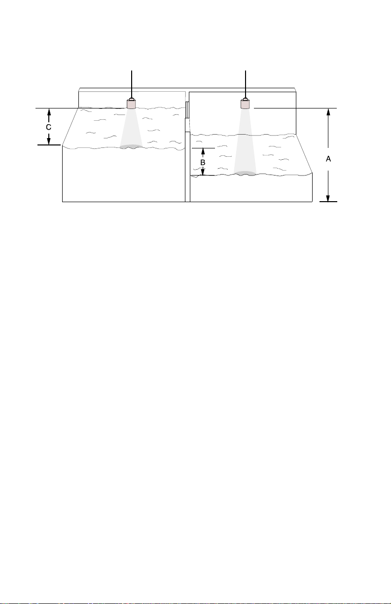
In order to use the MultiRanger Plus as a differential level detector TB-1 must be
wired as in Installation \ Installing the Transducer and both transducers must be
installed at the same level.
A = transducers must be at the same elevation ( P-3 ).
B = maximum differential ( Span, P-4 )
C = transducer should be mounted at least 0.3 m above
the highest liquid level and 0.3 m away from the wall
for every 3 m / ST-25 or 6 m / ST-50 of measurement.
Differential Level Example
The application is to monitor the differential level across a sewage bar screen. When
a differential level of greater than 12" is obtained, it is required that a rake be started.
If the water level on either side rises above 20", a high level alarm is required.
The height from the common ( low ) level to the transducer face is 4 ft . A 4 - 20 mA
output corresponding to the differential is required, and the 20 mA has been arbitrarily
set to correspond to a 24" differential ( span ). In the event of a loss of echo, the
MultiRanger Plus should go into a fail-safe high after 5 minutes.
select:
P-1 enter option "4", units in inches
P-2 enter option "3", differential level
P-3 enter "48", empty distance to transducer
P-4 enter "24", span
P-5 enter "11.81", blanking distance, ( use factory setting )
P-6 enter option "24", 4 - 20 mA output
P-7 enter "1", display max 1 digit after decimal
P-8 enter option "4", relay 1 - differential alarm
P-9 enter "12", relay 1 - rake on
This would be used only to initiate
the rake control circuitry.
PL-443 6 – 24
Page 59

P-10 enter "6", relay 1 - reset this value can be arbitrarily set
P-11 enter option "1", relay 2 - alarm function
P-12 enter "20", relay 2 - alarm ON
P-13 enter "19", relay 2 - alarm OFF
P-20 enter option "14", relay 5 - scanner
P-32 enter option "1", mA output on differential
P-68 enter "393.7", fill damping 393.7 in / min. Normally this level
would rise over a period of days or weeks,
therefore damping requirements would be fairly
slow. Typically, the factory set damping of 32.81
can be used.
P-69 enter "393.7", empty damping - same as fill damping
P-74 enter option "1, fail-safe high
P-75 enter "5", fail-safe timer
RUN
to re-enter run mode
CAL
PL-443 6 – 25
Page 60

OPEN CHANNEL MEASUREMENT
APPLICATION PARAMETERS
General Relays Pump Control Vol. & Disp.
OCM Totalizer Custom Filter
Conversion
P-1 units P-8 1 function P-23 submers. P-34 tank P-40 primary P-51 OCM sim. P-60 full P-68 fill damp
P-2 mode P-9 1 on P-24 1 hrs. P-35 dim. A P-41 time P-52 factor P-61 empty P-69 empty damp
P-3 empty dist. P-10 1 off P-25 2 hrs. P-36 dim. L *P-42 expon. P-53 decimal P-62 offset P-70 rate disp.
◊P-4 span P-11 2 function P-26 3 hrs. P-37 convert *P-43 flume dim. P-54 low tot. P-63 vel. 20 °C P-71 rate avg.
P-5 near blank P-12 2 on P-27 4 hrs. P-38 disp. offset P-44 spare P-55 high tot. P-64 vel. P-65 P-72 fuzz filter
P-6 mA out P-13 2 off P-28 5 hrs. P-39 disp. opt’n ◊P-45 max. head P-56 remote tot. P-65 temp. P-73 agitator
P-7 decimal P-14 3 function P-29 run-on P-46 max. flow P-57 flow samp. P-66 max. temp P-74 f-s mode
P-15 3 on P-30 run-on P-47 auto zero P-58 flow samp. P-67 min. temp P-75 f-s timer
P-16 3 off P-31 spare P-48 cutoff P-59 time samp.
P-17 4 function P-32 DLD mA out P-49 decimal
P-18 4 on P-33 totaling P-50 mA out
P-19 4 off
P-20 5 function
P-21 5 on
P-22 5 off
P-# required parameters
P-# optional parameters
P-# parameters not required
* either parameter, depending on P-40
◊ same
Page 61

OCM APPLICATION
This application is specific to monitoring the flowrate in one of the four following
categories of primary measuring devices. Refer to the respective drawings at the end
of this section for weir and flume outlines and transducer location.
Single Exponential, these are flumes and weirs that can be characterized
by a single exponential term ( P-40 = 1 ) i.e. Q = K H
where : Q = flow
K = constant
H = head
x = exponent, characteristic to the primary
measuring device (flume or weir)
Examples :
Primary measuring device
exponent
Suppressed rectangular, Cipolletti weir, or Venturi flume 1.50
Parshall Flume, or Leopold Lagco 1.55
V-notch weir 2.50
etc ......
Refer to manufacturer’s specifications for the exact exponent.
The exponents listed above are for reference only.
X
.
Palmer-Bowlus flumes : typically those manufactured by Plasti-Fab
or Warminster Fiberglass ( P-40 = 2 )
H-flumes : excluding HS and HL sizes, as developed by the U.S.
Department of Agriculture, Soil Conservation ( P-40=3 )
Other : these are primary measuring devices that do not fit the
first three categories ( P-40 = 4 )
As most OCM applications are outdoors, the use of a temperature sensor is strongly
recommended for optimum accuracy. Refer to Functional \ Temperature.
PL-443 6 – 27
Page 62

Flow readings are calculated by the MultiRanger Plus as a function of the head under
the transducer, installed upstream from the primary measuring device ( P-40 ). The
flows are then accumulated in the arbitrary volume units chosen per the time units of
P-41 in an 8 digit totalizer. In the event of a loss of echo, the totalizer will continue
being incremented by the flowrate established from the last valid echo. The totalizer
will stop being incremented and hold its last updated value when in the program mode
or if the fail-safe timer expires ( "LOE" is displayed ).
The totalizer contents are stored in RAM and will be lost in the event of a power
failure. However, after every 1 hour of continuous operation, the totalizer contents are
stored in the EEPROM. Thus, after a power failure, the totalizer will be loaded with
the last value stored. Once the totalizer has been filled ( 99999999 ) it will
automatically reset itself to zero and resume totalling.
The MulitRanger Plus can be programmed ( P-39 ) to normally display one of the
following readings :
» enter option "0", hold last reading selected in run mode
» enter option "1", high total: 4 highest digits of the 8 digit totalizer
» enter option "2", low total: 4 lowest digits of the 8 digit totalizer
» enter option "3", head
» enter option "4", flow
It must be noted that only half of the totalizer digits
can be accessed or viewed at one time.
e.g.
high total low total
P-54 P-55
8 digit total
1325 4769
To momentarily view an alternate reading while in run mode and P-39 ≠ 0, press the
desired programmer key ( "READ" is not applicable to OCM ).
e.g.
normal display is high total, P-39 = 1
2
low total is momentarily displayed
normal display of the
high total returns
If P-39 = 0, alternate readings cannot be momentarily displayed. Pressing the desired
key will change the display and hold it there until the next alternate reading is selected.
PL-443 6 – 28
Page 63

In the program mode, the high and low totals can be viewed or preset to any value by
P-54 and P-55 respectively.
The flow readings ( high and low total ) may be scaled down by factors of 10 ( P-52 )
to slow down the totalizer’s rate of fill and its decimal point ( P-53 ) positioned for the
resolution required. To change the scaling factor or decimal point location after
totaling has begun, record the high and low totals and reset the totalizer to zero.
The MultiRanger Plus can be programmed to ignore low head, i.e. flows for heads
less than that set in P-48 will not be accumulated in the totalizer. The low head cutoff
is measured in % of maximum head ( P-45 ).
Further to alarm and pump functions, relays may be programmed to act as a
momentary contact closure for a remote totalizer, flow sampler or time sampler ( refer
to Application \ Relays ). The duration of a momentary contact closure is 200 msec for
which the corresponding relay status LED will flash. As a remote totalizer relay, the
contact is closed each time the displayed total is increased by the amount entered into
P-56. As a flow sampler relay, the contact is closed each time the volume of liquid as
set by P-57 and P-58 is pumped. As a time sampler relay, the contact is closed at the
rate of the time period.
The mA output responds to the head or flow ( P-50 ). In the event of fail-safe due to
loss of echo, the mA output will respond as programmed by P-6 and P-74.
When programming the MultiRanger Plus for the OCM function, the empty distance to
transducer ( P-3 ) may be considered and entered as the distance from the transducer
face to the 0 head or no flow reference level. If this measurement is not easily
obtained, P-3 can be estimated and corrected via P-47. This is referred to as the Auto
Zero calibration and requires the MultiRanger Plus to compare a physical
measurement ( from wall gauge, dipstick or stilling well ) to the ultrasonic
measurement via P-47. Refer to OCM Auto Zero Example.
It should also be noted that when operating in the OCM function: percent display,
volume conversion ( P-34 ) and convert display ( P-37 ) are inoperative. Empty
calibration ( P-61 ) must be clear, i.e. 4 hyphens in the display.
PL-443 6 – 29
Page 64
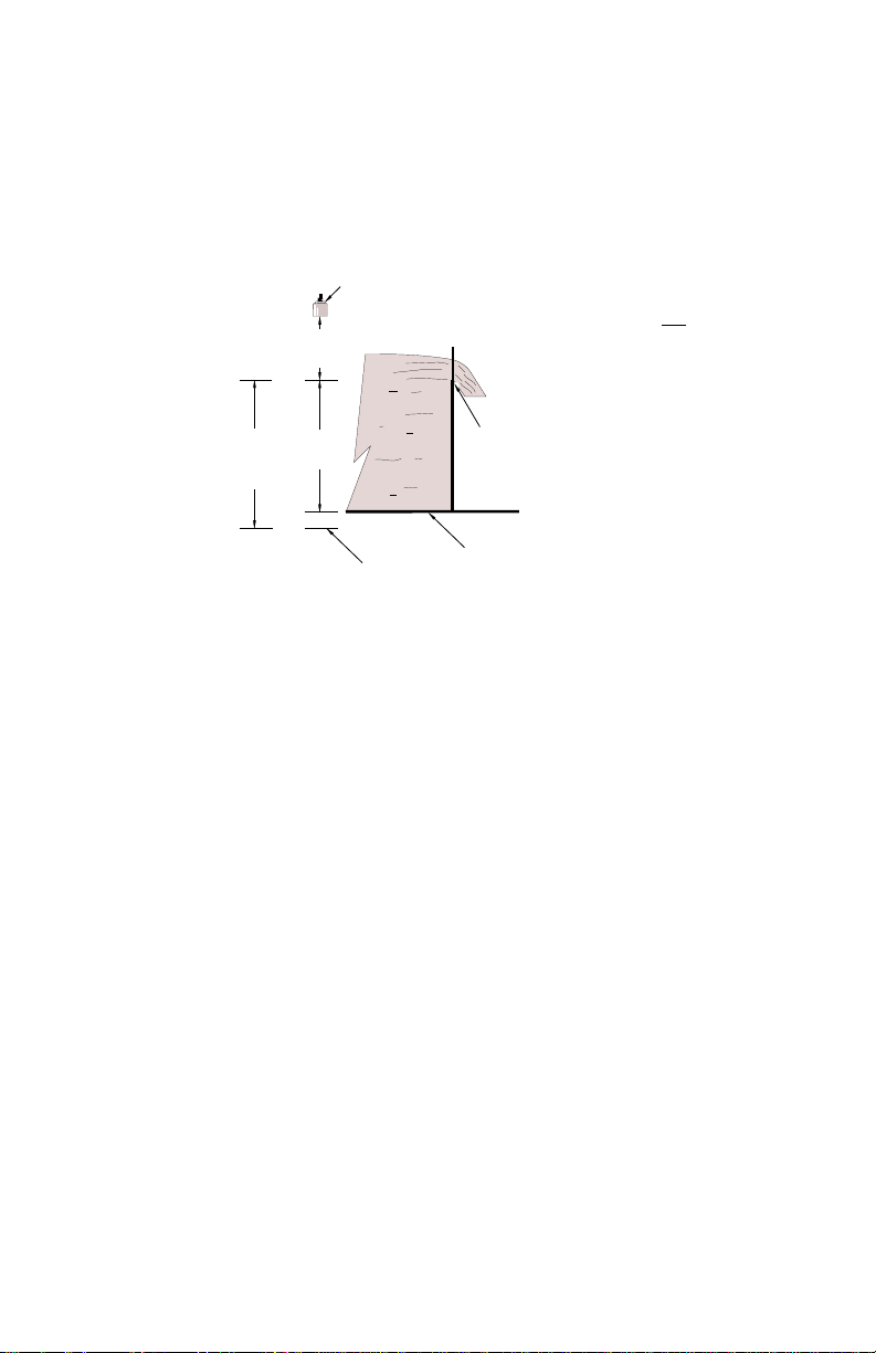
An important consideration in OCM applications is that many primary measuring
P-87 = d x 110
P-3
devices have the potential of running dry. In such cases, it must be insured that the
range extension ( P-87 ) is sufficient so that the floor of the channel or of the
converging section of the flume can be read. Otherwise, false readings may be
obtained indicating flow.
transducer
P-3
range
OCM Example
9" Parshall Flume
» max flow rate - Q max = 4.112 MGD
» max head - H max = 1.61
% range
extension
P-87
d
depth
+ 10%
margin
Q = 1.98 H
bottom of weir notch,
0 head
channel bottom
1.53
where Q = flow rate, MGD ( million gallons per day ),
H = head, feet
= 4,112,000 gal. / day
» transducer is mounted 3 ft above the zero flow level
» max flow rate display = 4,112
i.e. one count = 1000 gal.
PL-443 6 – 30
Page 65

select:
P-1 enter option "3", units in feet
P-2 enter option "5", OCM
P-3 enter "3", zero level distance to transducer
P-4 enter "1.61", max head
P-5 enter "1", near blanking distance, minimum allowable
P-39 enter option "4", display flowrate in units per day
P-40 enter option "1", primary measuring device - exponential
P-41 enter option "4", flowrate time units - per day
P-42 enter "1.53" exponent from manufacturer’s specs.
for 9" Parshall Flume
P-46 enter "4112", max flow in thousand gal / day
P-49 enter option "3", flowrate decimal point display max 3 digits
after decimal
P-52 enter option "0", totalizer convert display total is divided by 1 before
being displayed or 1 count per thousand gallons.
P-53 enter option "2", totalizer decimal point display 2 digits after
decimal or resolution equals 1/100th of a count.
P-68 enter "32.81", fill damping 32.81 ft / min. As the head would
fluctuate over a period of hours, damping
requirements would be fairly low. Typically, the
factory set damping of 32.81 can be used.
P-69 enter "32.81", empty damping - same as fill damping
RUN
to re-enter run mode
CAL
OCM Auto Zero Example
Further to OCM Example, the following is required :
» alarm at 10% overflow ( approx. = 1.8 ft ) and 0 head
» in the event of loss of echo, the MultiRanger Plus is to go into
low alarm after 45 sec.
» head to read to 1 decimal place
» sampler contact every day
» head under "1" ( 40 thousand gal / day ) not be totalized
» 4 - 20 mA output to respond to flow
PL-443 6 – 31
Page 66

select :
P-3 enter "3.33" estimated empty distance to transducer
P-6 enter option "2", 4 to 20 mA
P-7 enter option "1", decimal location for head display
max 1 digit after decimal
P-8 enter option "1", relay 1 - alarm function
P-9 enter option"1.8", relay 1 - alarm ON
P-10 enter "1.5", relay 1 - alarm OFF
P-11 enter option "1", relay 2 - alarm function
P-12 enter "0", relay 2 - alarm ON
P-13 enter ".3", relay 2 - alarm OFF
P-14 enter option "13", relay 3 - time sampler contact
P-47 Auto Zero
CLR ENTER
Press and then 4 hyphens must appear in the display.
MEAS
Press at least 5 times to insure that the MultiRanger Plus will
obtain a stable ultrasonic measurement. The resultant reading will
be the apparent head with respect to the estimated P- 3 = 3.33 ft .
Enter "physical head measurement", over the displayed value
previously obtained. This is the true head measurement from wall
gauge, dipstick or stilling well, taken at the same time as the
ultrasonic measurement and representing the same head
measurement point as seen by the transducer. The physical head
measurement must not be in the near blanking zone. An offset value,
which is the apparent head minus the true head, is automatically
calculated and entered into P-62. P-62 can only be cleared by P-47.
P-48 enter "5.2", low head cutoff is 5.2% of P-45 flow for head
below "1" ( 40 thousand gal. / day )
will not be totalized
1" = 0.052 = 5.2%
12" / ft x 1.61 ft
P-50 enter option "2", mA output responds to flow
P-59 enter "1", time sampler control closure once every hour
P-74 enter option "2", fail-safe low
P-75 enter option ".75", fail-safe timer, 45 sec.
RUN
CAL
to re-enter run mode
PL-443 6 – 32
Page 67
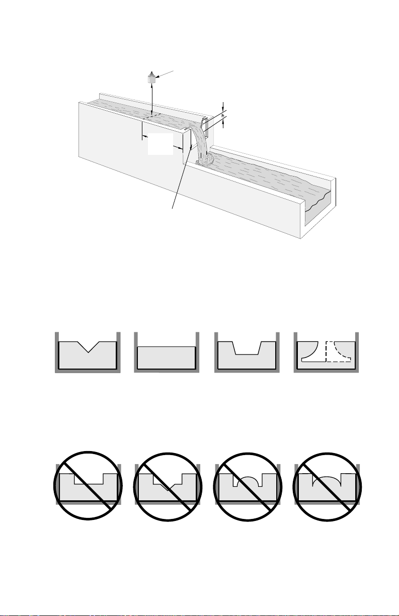
Single Exponential, P-40 = 1
Weirs
3 to 4
h
max
weir profile
* The transducer must be above the
Applicable Weir Profiles
transducer *
maximum head by at least the
blanking value, P-5.
V - notch or
triangular
suppressed
rectangular
Non-Applicable Weir Profiles
contracted
compound
rectangular
Flows through these weirs may be measured using the
universal head vs flow characterization, P-40 = 4.
PL-443 6 – 33
cipolleti or
trapezoidal
Poebing
sutro or
proportional
approximate
exponential
Page 68

Single Exponential P-40 = 1 ( cont’d )
FLUMES
Parshall Flume
0
head
C
plan
transducer
2
/3 C
» sized by throat width
» set on solid foundation
» general free flow equation is Q = K H
» For rated flows under free flow conditions, the head is measured
at 2 / 3 the length of the converging section from the beginning
of the throat section.
» Position the transducer such that it is centered over the flow at a
minimum head.
Khafagi Venturi
front
15 cm ( 6" )
transducer
x
plan
side
where: Q = flow rate
K = constant
H = head
x = exponent
0
head
» for rated flows under free flow conditions, the head is measured 15 cm
( 6" ) upstream from the beginning of the converging section.
» position the transducer such that it is centered over the flow at a
minimum height of 30 cm ( 12" ) above the maximum head.
PL-443 6 – 34
sidefront
Page 69

Single Exponential, P- 40 = 1 (cont’d)
transducer
FLUMES (cont’d)
Leopold Lagco (as manufactured by Leopold Co., Inc.)
throat
plan
side
diverging
0
head
converging
point of measurement
» designed to be installed directly into pipelines and manholes
» Leopold Lagco may be classed as a rectangle Palmer-Bowlus flume
» sized by pipe ( sewer ) diameter
» for rated flows under free flow conditions, the head is measured at a
point upstream referenced to the beginning of the converging section.
Refer to the following table:
front
Flume Size Point of Measurement
(pipe dia. in inches) cm inches
» general free flow equation is Q = K H
» position the transducer such that it is centered over the flow at a
minimum height of 30 cm ( 12" ) above the maximum head.
PL-443 6 – 35
4 - 12 2.5 1
15 3.2 1
18 4.4 1 3/
21 5.1 2
24 6.4 2
30 7.6 3
42 8.9 3
48 10.2 4
54 11.4 4
60 12.7 5
66 14.0 5
72 15.2 6
x
, where: Q = flow rate
1
/
4
4
1
/
2
1
/
2
1
/
2
1
/
2
K = constant
H = head
x = exponent
Page 70

Single Exponential, P-40 = 1 ( cont’d )
FLUMES ( cont’d )
plan
Flow through the following flumes may be measured using the
universal head vs flow characterization, P-40 = 4.
Cutthroat Flume
» similar to Parshall flume
except that the floor is flat
bottomed and throat has no
virtual length
» refer to manufacturer’s
specifications for flow
equation and point of head
measurement.
Trapezoidal Flume
» similar to Parshall flume
except that the floor is
flat bottomed and walls
are sloped.
isometric
Dual Range ( nested ) Parshall Flume
plan
PL-443 6 – 36
» two flumes, a
larger on top of
the smaller, in
order to handle
a larger range
of flows.
front
Page 71

Palmer-Bowlus Flume, P-40 = 2
transducer
front
D
( typically those manufactured by Warminster Fiberglass or Plasti-Fab )
Q
D / 2, point of
measurement
» sized by pipe diameter, D. Enter value ( in units of P-1 ) into P-43.
» flume relief is trapezoidal
» designed to install directly into pipelines and manholes
» head is referenced to bottom of the throat not to bottom of pipes
» for rated flows under free flow conditions, the head is measured at a
distance of D / 2 upstream from the beginning of the converging section
» position the transducer such that it is centered over the flow at a
minimum height 30 cm ( 12" ) above the maximum head
plan
0
head
side
PL-443 6 – 37
Page 72

H Flumes, P-40 = 3
( as developed by the U.S.Department of Agriculture, Soil Conservation Service )
transducer
Q
point of
measurement
plan
D
front
side
» sized by max depth of flume, D. Enter value ( in units of P-1 ) into P-43.
» approach is preferably rectangular, matching width and depth for
distance 3 to 5 times the depth of the flume
» flow range 100 : 1
» may be installed in channels under partial submergence
( ratio of downstream level to head ).
Typically: » 1% error @ 30% submergence
» 3% error @ 50% submergence
» for rated flows under free flow conditions, the head is measured at a
point downstream for the flume entrance.
Flume Size Point of Measurement
( D ft ) cm inches
0.5 5 1 3/
0.75 7 2 3/
1.0 9 3 3/
1.5 14 5 1/
2.0 18 7 1/
2.5 23 9
3.0 28 10
4.5 41 16 1/
4
4
4
2
4
3
/
4
4
» H flumes come with a flat or sloping floor.
The same flow table can be used as error is less than 1%.
» position the transducer such that it is centered over the flow at a
minimum height of 30 cm ( 12" ) above the maximum head.
PL-443 6 – 38
Page 73

Other, P- 40 = 4
Where the primary measuring device does not fit one of the three other categories,
P-40 may be programmed for one or two head versus flow characterizations:
» P-40 = 4 : curved
» P-40 = 5 : linear
Select the characterization which most closely fits the flow characteristics of the
primary measuring element.
linear
F
l
curved
o
w
Head
Characterization is achieved by entering the head ( H parameter ) and corresponding
flow ( F parameter ) either from emperical measurement or from the manufacturer’s
specification. The more breakpoints that are defined, the more accurate will be the
flow measurement. Breakpoints should be concentrated in areas exhibiting the higher
degrees of non linear flow. A maximum of eleven breakpoints can be defined.
Head data is entered in the linear units selected ( P-1 ) and flow data is entered in the
desired units of flowrate.
Other Flumes Example
The application is to measure the flow across a 4 ft rectangular weir with end
contractions. The flow is characterized by the following formula:
cfs = 3.33 ( L-0.2H ) H
1.5
where: cfs = flow in cu ft / sec
L = length of crest
H = head
PL-443 6 – 39
Page 74
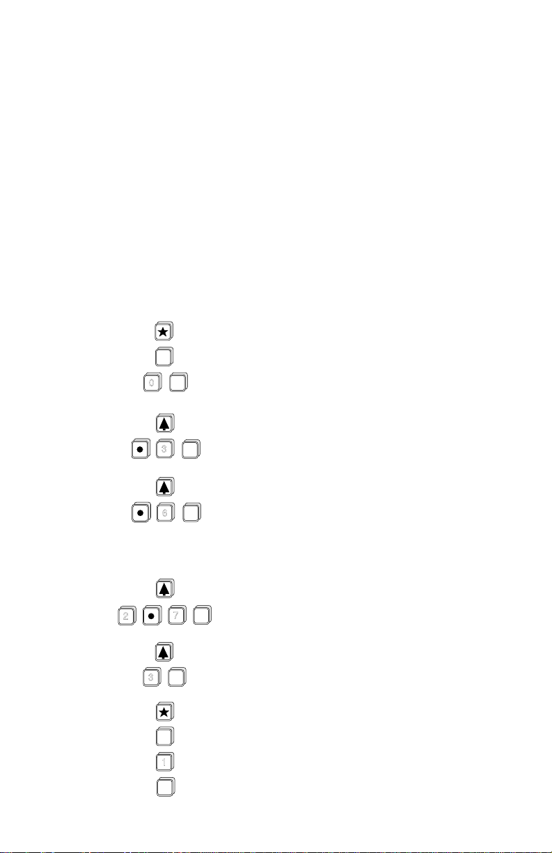
select :
P-1 enter option "3", units in feet
advance to:
P-2 enter option "5", OCM
P-3 enter "4", empty distance to transducer
P-4 enter "3", span
P-5 enter "1", near blanking distance
P-39 enter option "4", display flowrate
P-40 enter option "4", universal head vs flow
press display will show
H - 1
ALT
DISP
ENTER
0
- - - -
0.0 0 0
H - 2
(then)
- - - -
ENTER
3
ENTER
6
» » »
ENTER
2
7
ENTER
3
ALT
DISP
1
ALT
DISP
PL-443 6 – 40
0.3 0 0
H - 3
0.6 0 0
H - 10
2.7 0 0
H - 11
3.0 0 0
F - 11
F - 11
F - 1
- - - -
(then)
(then)
(then)
(then)
- - - -
- - - -
- - - -
- - - -
Page 75
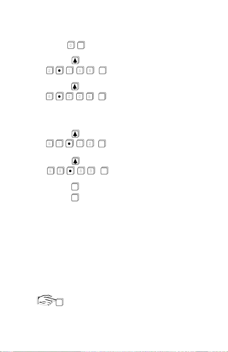
press display will show
2
6
5
5 8
ENTER
0
5
1
0
ENTER
6
ENTER
50
0.0 0 0
F - 2
2.1 5 6
F - 3
6.0 0 5
(then)
(then)
- - - -
- - - -
» » »
F - 10
(then)
- - - -
1
1
8
ALT
DISP
CLR
ENTER
2
ENTER
3
5 1.1 2
F - 11
5 8.8 3
(then)
- - - -
F - 11
P - 4 0
P-41 enter option "1", flowrate time units per sec
P-46 enter "58.83", maximum flowrate in cu ft / sec
P-49 enter option "3", flowrate decimal point display max
3 digits after decimal
P-52 enter option "0", totalizer convert display is divided by 1 before
being displayed or 1 count per thousand cu ft
P-53 enter option "2", totalizer decimal point display 2 digits after
decimal or resolution equals 1/100th of a count
RUN
to re-enter run mode
CAL
PL-443 6 – 41
Page 76

APPLICATIONS WITH STANDPIPES
In many solids and liquid applications, access to the vessel must be made via a
standpipe. In such cases, Milltronics can provide flange mounted transducers that will
readily mate to the standpipe.
The maximum standpipe length that can be used without additional near blanking
( P-5 not greater than 0.3 m ) is 200 mm ( 8" ). For greater standpipe lengths, up to
30" long, near blanking must be extended to 150 mm ( 6" ) beyond the end of the pipe.
The preferred dimension when selecting a standpipe arrangement is a 100 mm ( 4" )
diameter pipe, 300 mm ( 12" ) long. Near blanking would be set at 460 mm ( 18" ).
Standpipe Example
Referring to Volume Application \ Volume Example, if the transducer were mounted to
a 150 mm diameter flanged standpipe 0.5 m long, instead of a 1 m diameter manhole,
the following will be required :
select :
P-5 enter ".65", near blanking
0.50 m ( standpipe length )
+0.15 m ( blanking past pipe )
0.65 total blanking distance
to re-enter run mode.
RUN
CAL
PL-443 6 – 42
■
Page 77

PARAMETER DESCRIPTION
( F ) indicates the parameter’s factory setting, where applicable.
For reference only, factory set values
may change with software revisions.
( V ) indicates that parameter can be viewed only, not entered.
P-0 security
This parameter can be used to lock out the programmer such that the
content of parameters P-1 through P-99 can not be changed. This
however does not prevent the parameters from being selected and
viewed. The programmer is locked out if the content of P-0 is of any
value other than 1954. P-0 can only be direct accessed.
content = 1954, programmer functional ( F )
≠ 1954, programmer locked out
= -1, pumps active during simulation
P-1 units of calibration and display
enter: 1 = meters ( F ) 1
2 = centimeters 2
3 = feet 3
4 = inches 4
= calibrate in meters, display in %
*
= calibrate in centimeters, display in %
*
= calibrate in feet, display in %
*
= calibrate in inches, display in %
*
For % display, entry must be made as #
and will be displayed as " # P "
e.g. Press and then , the display will show " 3 P ".
3
P-2 mode of measurement
enter: 1 = material level
2 = space ( F )
3 = differential level
4 = volume totalizer ( pump totalizer )
5 = OCM ( open channel measurement )
P-3 empty distance to transducer
enter desired amount ( F = 10.00 m )
PL-443 7 – 1
*
Page 78

P-4 span
» distance between full ( high ) and empty ( low ) levels
» maximum level differential if DLD ( P-2 = 3 ) is selected
» maximum head if OCM ( P-2 = 5 ) is selected
enter desired amount ( F = 10.00 m )
P-5 near blanking
normally leave at factory setting. However for blanking extension, entry
must be slightly larger than distance to end of standpipe or far side of
obstruction. Blanking should not extend all the way into span level.
Some margin of material span should be allowed to avoid loss of echo.
enter distance required, in units as set in P-1 ( F = 0.300 m )
P-6 milliamp output
enter: 0 = off
1 = 0 to 20 mA
2 = 4 to 20 mA
3 = 20 to 0 mA
4 = 20 to 4 mA
P-7 decimal point location
Sets the maximum number of digits after the decimal. The number of
digits after the decimal will automatically reduce to avoid display overflow.
enter: 0 = no digits after decimal
1 = one digit after decimal
2 = two digits after decimal ( F )
3 = three digits after decimal
P-8 relay 1 function
Refer to Functional \ Relays.
enter desired option ( F = 0 )
P-9 / 10 relay 1- ON / OFF setpoints
enter level in units as selected in P-1 or °C ( F = - - - - )
PL-443 7 – 2
Page 79

P-11 relay 2 function
Refer to Functional \ Relays.
enter desired option ( F = 0 )
P-12 / 13 relay 2 - ON / OFF setpoints
enter level in units as selected in P-1 or °C ( F = - - - - )
P-14 relay 3 function
Refer to Functional \ Relays.
enter desired option ( F = 0 )
P-15 / 16 relay 3 - ON / OFF setpoints
enter level in units as selected in P-1 or °C ( F = - - - - )
P-17 relay 4 function
Refer to Function \ Relays.
enter desired option ( F = 0 )
P-18 / 19 relay 4 - ON / OFF setpoints
enter level in units as selected in P-1 or °C ( F = - - - - )
P-20 relay 5 function
Refer to Functional \ Relays.
enter desired option ( F = 0 )
P-21 / 22 relay 5 - ON / OFF setpoints
enter level in units as selected in P-1 or °C ( F = - - - - )
PL-443 7 – 3
Page 80

Parameters P-23 through P-33 are used specifically for pump applications.
" ratio " setpoints
" service hours "
P-23 submersible transducer
P-24 relay 1 pump log *
P-25 relay 2 pump log *
P-26 relay 3 pump log *
P-27 relay 4 pump log *
P-28 relay 5 pump log *
Refer to Applications \ Pump Control Applications.
enter: 0 = normal ST- series transducer ( F )
1 = submersible transducer
These parameters are divided into three levels of subparameters:
*
Access is made by scrolling through the levels.
press display will show
PL-443 7 – 4
» " service hours " log
» " pump starts " log
» " ratio " setpoint
initial access ( service hours )
" pump starts "
Page 81
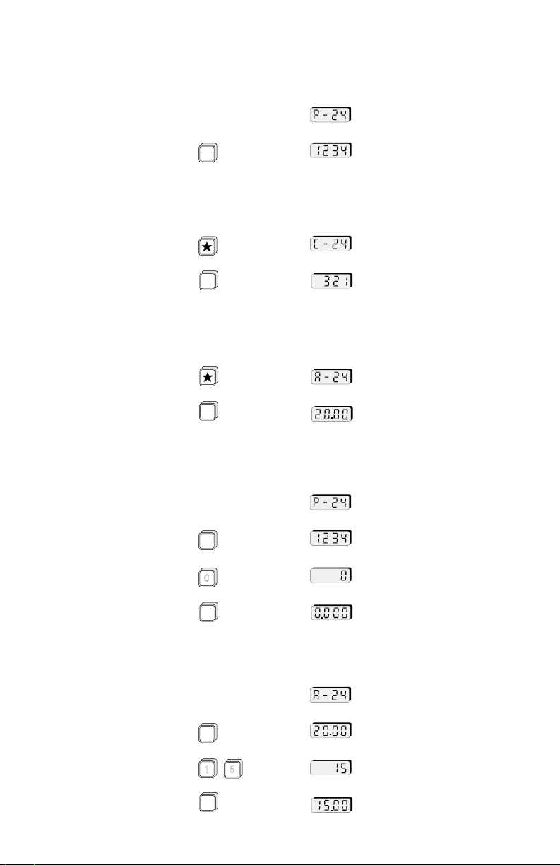
press display will show
factory setting
To view the service hours
at the ‘P’ parameter
ALT
DISP
e.g. 1,234 hours of service
( F = 0.000 )
To view the number of starts
at the ‘C’ parameter
ALT
DISP
e.g. 321 pump starts ( F = 0 )
To view the ratio setpoint
at the ‘A’ parameter
ALT
DISP
To reset or preset the " service hours " or " pump starts" log
e.g. " service hours " selected
ALT
DISP
e.g. 1,234 hours
0
ENTER
To set the service " ratio "
ALT
DISP
1
5
ENTER
PL-443 7 – 5
e.g. reset to zero
e.g. 0 " service hours "
" ratio " setpoint
e.g. 20
e.g. 15
" ratio " setpoint is now 15
Page 82

P-29 pump run-on interval
the cyclical period in hours, in which a pump run-on duration may
occur. The initial interval begins upon return to the run mode or
resumption of power to the MultiRanger Plus. Subsequent intervals
begin at the end of the previous interval. Intervals end after the time
entered has expired or when the power or run mode is interrupted.
enter interval in hours ( F = - - - - )
P-30 pump run-on duration
the amount of time which the lead pump will continue pumping
after it has reached its OFF setpoint.
enter duration in seconds ( F = 0 )
P-31 spare
P-32 DLD milliamp output
when operating on the DLD mode, the milliamp output can be set to
correspond either to the differential or to the level under transducer #1
enter: 1 = differential ( F )
2 = level
P-33 inflow / discharge totaling
refer to Applications \ Pump Totalizer Application
enter: 1 = estimated inflow or discharge volume as added
to the pumped volume total ( F )
2 = estimated inflow or discharge volume is omitted
from the pumped volume total.
PL-443 7 – 6
Page 83

Parameters P-34 through P-39 are used for volume and display conversion.
P-34 tank shape for volumetric conversion
enter: 0 = non volume - linear level measurement ( F )
1 = flat bottom
2 = conic or
pyramidic bottom
3 = parabolic bottom
or
4 = half sphere bottom
5 = flat slope bottom
6 = horizontal cylinder,
flat ends
7 = horizontal cylinder,
parabolic ends
8 = sphere
( cont’d )
PL-443 7 – 7
Page 84

9 = custom tank design *
return to ‘P’ parameters
( refer to Applications \ Volume Application )
This option is divided into two levels of subparameters:
*
H - # where: H = level coordinate
F - # F = volume coordinate
# = breakpoint 1 to 11
Access is made by scrolling through the levels.
press display will show
ALT
DISP
9
ENTER
Setting of the subparameters is done in the same way
as with the ‘P’ parameters.
To exit the " H " and " F " subparameters:
If P-34 ≠ 0, reading will be in percent of full volume. For
volumetric reading, set conversion factoring by using P-37.
P-35 tank dimension ‘A’
the height of the bottom section of tank shapes 2, 3, 4, 5 or
the length of one end section in tank shape 7.
( not required for other tank shapes )
enter " dimension A ", in units selected per P-1 ( F = 0000 )
PL-443 7 – 8
select any ‘H’ or ‘F’ parameter
CLR
Page 85

P-36 tank dimension ‘L’
horizontal length of tank shape excluding parabolic ends
( not required for other tank shapes ).
enter " dimension L ", in units selected per P-1 ( F = 0.0 0 0 )
P-37 convert display
parameter value is the factor by which the measurement is to be
multiplied by before being displayed. Range is 0.001 to 9999.
enter desired factor ( F = 1 )
P-38 display offset
this value is added to material space, volume or ullage measurement
before being displayed ( P-39, P-76 or " * " key ). The mA output and
alarms are not affected by the offset. The display offset is entered in
the units programmed, subject to P-1, P-34 and P-37.
enter offset required ( F = 0.000 )
P-39 display reading options
enter : 0 = hold last alternate reading selected ( F )
1 = high total: 4 highest digits of the 8 digit totalizer
( pumped volume and OCM only )
= point 1: DLD level / transducer #1
2 = low total: 4 lowest digits of the 8 digit totalizer
( pumped volume and OCM only )
= point 2: DLD level / transducer #2
3 = head ( OCM only )
4 = flow rate ( OCM only )
5 = reading level, space, differential, volume or ullage
In the run mode, the programmer keys illustrated can be pressed
to view alternate readings. The display will return to the reading
option selected ( except option 0 ) after momentarily displaying
alternate reading.
PL-443 7 – 9
0
1
2
3
4
Page 86

Parameters P-40 through P-50 used specifically for
return to ‘ P ’ parameters
OCM applications. Refer to Applications.
P-40 primary measuring device
enter option: 1 = exponential ( F )
* these options are divided into 2 levels of subparameters:
H - # where: H = level coordinate
F - # F = flow coordinate
# = breakpoint 1 to 11
Access is made by scrolling through the levels.
press display will show
ALT
DISP
2 = Palmer-Bowlus
3 = H-flume
4 = universal head vs flow - curve *
5 = universal head vs flow - linear *
Setting of the subparameters is done in the same way
as with the ‘ P ’ parameters.
To exit the ‘ H ’ and ‘ F ’ subparameters
PL-443 7 – 10
4
ENTER
select any ‘ H ’ or ‘ F ’ parameter
CLR
Page 87

P-41 flow rate time units
enter option: 1 = per second
P-42 OCM exponent
exponent for primary measuring devices, P-40 = 1 where Q = K H
Obtain from manufacturer’s specifications.
enter " exponent " ( F = 1.550 )
P-43 flume dimension ( P-40 = 2 or 3 )
enter ‘ D ’, flume size in units of P-1 ( F = 1.000 )
P-40 = 2
D
2 = per minute
3 = per hour
4 = per day ( F )
x
P-40 = 3
D
Palmer Bowlus
D = pipe or sewer dia.
P-44 spare
P-45 maximum head
this is the head corresponding to the max flow rate. This parameter
is identical to P-4, span. A change to either parameter will
simultaneously change the other. ( F = 10.00 )
P-46 maximum flow rate
this is the flow rate which occurs at maximum head and determines
the mA output span ( refer to Functions \ Analog Output ).
Obtain from manufacturer’s specifications.
enter " maximum flow rate ", volume units are arbitrary ( F = 1000 )
PL-443 7 – 11
H Flume
Page 88

P-47 Auto zero
this parameter allows automatic zero calibration for the empty
distance to transducer parameter ( P-3 ) when the physical
measurement is not obtainable.
P-3 is the estimated empty distance to the transducer face
with the transducer aimed at the proper portion of the crest in the
open channel and at a height of at least 1 ft above maximum head.
MEAS
Press at least five times and until a stable reading is obtained
on the display. The reading, regardless of the height of the
transducer, will be the apparent head with respect to the estimated
empty distance, P-3. Enter the actual physical measurement of head
at a point beneath the transducer.
ENTER
Press , the MultiRanger Plus will then calculate the correct
zero reference level. The offset will be automatically entered into P-62.
P-48 OCM low head cutoff
flows for head below this level will not be totalled. Unit of cutoff is
percent of maximum head (P-45)
enter "percentage required" (F=5.000)
P-49 OCM decimal point
sets the maximum number of digits after the decimal for display of
flow rate ( P-39 = 4 ). The number of digits after the decimal will
automatically reduce to avoid display overflow.
enter: 0 = no digits after decimal
1 = one digit after decimal
2 = two digits after decimal ( F )
3 = three digits after decimal
P-50 OCM mA output
refer to Functional \ Analog Output
enter: 1 = mA responds to head ( F )
2 = mA responds to flow
PL-443 7 – 12
94/09/20
Page 89

P-51 OCM simulation
ALT
DISP
press , display will show previous flow
enter head in units programmed, display will show head
ENTER
press , display will show corresponding flow
Parameters P-52 through P-59 are used specifically for OCM
and pump totalizer applications. Refer to Applications.
P-52 totalizer display factor
totalizer display of flow or volume pumped is factored by a power of
10 to determine the count per flow. The factor is selected as follows:
enter: – 3 =multiply by 1000
– 2 =100
– 1 =10
0 =divide by 1 ( F )
1=10
2 =100
3 =1,000
4 =10,000
5 =100,000
6 =1,000,000
7 =10,000,000
e.g. present flow rate is 450 gal / sec
if P-52 = 0, totalizer is incremented at a rate of 1 count per gallon
if P-52 = 3, totalizer is incremented at a rate of 1 count
per thousand gallons
P-53 totalizer decimal point location
sets the number of digits after the decimal point for the low total
only. The decimal point will not float.
enter: 0 = no digit after decimal
1 = one digit after decimal
2 = two digits after decimal ( F )
3 = three digits after decimal
P-54 low total
this parameter will display the 4 lowest digits of the 8 digit totalizer
used in pump totalizer or OCM application. The parameter will also
allow the display to be reset to any value. ( F = 00.00 )
PL-443 7 – 13
94/09/20
Page 90

P-55 high total
the parameter will display the 4 highest digits of the 8 digit totalizer
used in pump totalizer or OCM applications. The parameter will
also allow the display to be reset to any value. ( F = 0000 )
P-56 remote totalizer contact control.
a momentary closure of the remote totalizer contact occurs
once each time the entered flow or pumped volume has passed.
enter option: – 3 = 0.001
– 2 = 0.01
– 1 = 0.1
0 = 1( F )
1 = 10
2 = 100
3 = 1,000
4 = 10,000
5 = 100,000
6 = 1,000,000
7 = 10,000,000
P-57 flow sampler control
&
P-58
a momentary closure of the flow sampler contact occurs once each
time a volume of y x 10
x
, as defined by P-57 (x) and P-58 (y),
flows or is pumped.
enter P-57 (x) = base 10 exponent, – 3 to 7 ( F = 0 )
enter P-58 (y) = mantissa, 0.001 to 9999 ( F = 1.000 )
e.g. if P-57 = 3 and P-58 = 5, then a sampler contact closure will
occur each time 5 x 10
P-59 time sampler control
a momentary closure of the time sampler contact occurs each
time the entered amount of time in hours has elapsed ( F = - - - - )
PL-443 7 – 14
3
= 5000 units of volume has passed
Page 91

Parameters P-60 through P-67 are used to achieve
P-60 full calibration
this provides a measurement offset compensation on a full tank.
A measurement offset might occur when parameters 3 and 4
do not exactly match the tank dimensions referenced for
volume conversion. ( F = - - - - )
Fill tank as much a permissible, but without going
into the blanking zone.
Press , the MultiRanger Plus will take a measurement and
display the space or level ( P-2 ) in the linear units chosen ( P-1 )
regardless if percent, volume or convert display is used. Press
at least 5 times and insure that a stable reading is being obtained.
Enter the actual space or level ( P-2 ).
Press , the MultiRanger Plus will now calculate the correct
measurement offset to be used in future measurements
and automatically enter it into P-62.
specialized or custom calibration.
MEAS
MEAS
ENTER
P-61 empty calibration
this provides sound velocity compensation on an empty tank. This is
required on a volume application where the atmosphere in the tank
is other than air or the atmospheric temperature is constant but other
than 20 °C and no temperature sensor is being used. ( F = - - - - )
Empty tank is much as permissible. Leave filled with normal vapour
and at normal operating temperature.
MEAS
Press , the MultiRanger Plus will take a measurement and
display the space or level (P-2) in the linear units chosen (P-1)
regardless if percent, volume or convert display is used. Press
at least 5 times and insure that a stable reading is being obtained.
Enter the actual space or level ( P-2 ).
ENTER
Press , the MultiRanger Plus will now calculate in correct
sound velocity to be used in future measurements and automatically
enters it into P-63 and P-64.
PL-443 7 – 15
MEAS
Page 92

P-62 measurement offset
this displays the measurement offset: used in conjunction with a full
tank calibration, P-60, or an offset value may be entered directly.
The offset is added to the ultrasonic measurement such that its effect
will be carried through the reading ( P-39, P-76 or ), mA
output and relay setpoints. ( F = 0.000 )
P-63 sound velocity at 20 °C
can be used to enter the known velocity, at 20 °C, of sound in a
particular gas or vapour or to view the resultant velocity of an
empty calibration ( P-61 ), normalized to 20 °C. ( F = 344.1 )
the units of velocity are assumed to be:
meter / sec if P-1 = 1 ( meters ), 2 ( centimeters )
feet / sec if P-1 = 3 ( feet ), 4 ( inches )
P-64 velocity at P-65
can be used to enter the known velocity, at the temperature of P- 65,
of sound in a particular gas or vapour or to view the resultant velocity
of an empty calibration, at the temperature of P- 65. ( F = 344.1 )
the units of velocity are assumed to be:
meters / sec if P-1 = 1 ( meters ), 2 ( centimeters )
feet / sec if P-1 = 3 ( feet ), 4 ( inches )
P-65 air temperature in °C, as measured by temperature sensor or programmed
transducer operating temperature, if sensor is not used, enter temperature
required in °C ( F = 20 °C )
P-66 maximum air temperature in °C
records maximum air temperature measured by temperature sensor.
Press then to reset ( F = – 99 °C )
CLR
ENTER
P-67 minimum air temperature in °C
records the minimum air temperature measured by temperature sensor.
Press then to reset ( F = 150 °C )
CLR
ENTER
PL-443 7 – 16
Page 93

Parameters in P-68 through P-75 are used to stabilize the reading.
These are general purpose parameters, suitable for all applications.
P-68 fill damping
is the maximum rate at which the display reading and analog output
will change under filling conditions. The damping rate is measured
in P-1 units per minute and has a range of 0.001 to 9999. Thus the
smaller the number entered, the greater the damping.
enter desired amount ( F = 10.00 m / min ).
In pump up applications, for safe operation it is suggested that the
damping value allow for level changes at the pumps maximum
operating capacity, rather than the process design value.
P-69 empty damping
is the maximum rate at which the display reading and analog output
will change under emptying conditions. The damping rate is
measured in P-1 units per minute and has a range of 0.001 to 9999.
Thus the smaller the number entered, the greater the damping.
enter desired amount ( F = 10.00 m / min ).
In pump down applications, for safe operation it is suggested that the
damping value allow for level changes at the pumps maximum
operating capacity, rather than the process design value.
P-70 process rate display ( V )
display the rate of filling ( + ) or emptying ( – ) in P-1 units / minute
P-71 process rate filter
controls the response of the rate display
enter option: 0 = continually averaged rate
1 = update rate every minute or 50 mm ( F )
2 = update rate every 5 minutes or 100 mm
3 = update rate every 10 minutes or 300 mm
99 = programmable *
PL-443 7 – 17
Page 94
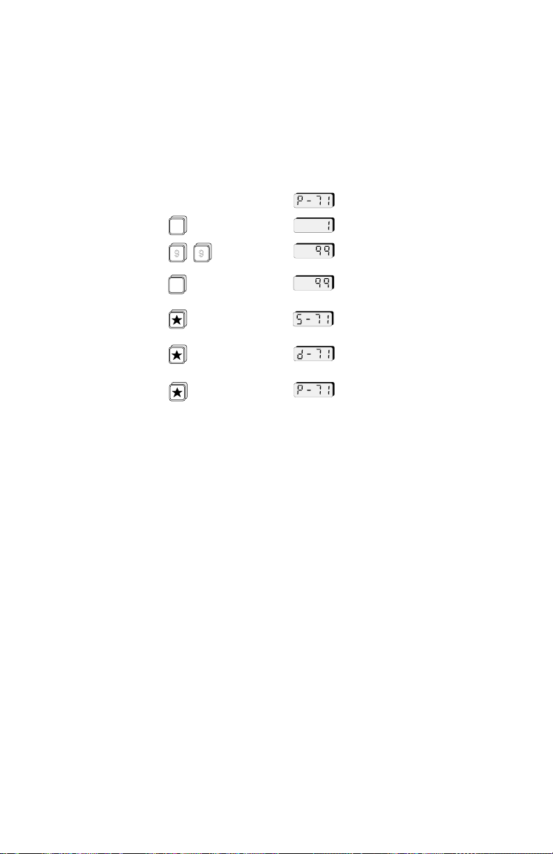
*
this option is divided into two levels of subparameters:
» S-71: time in seconds
» D-71: distance in linear units as set in P-1
Access is made by scrolling through the levels.
press display will show
ALT
DISP
9
9
ENTER
Setting the subparameters is done the same
way as with the ‘ P ’ parameters.
P-72 fuzz filter
the fuzz filter is designed to keep the display constant when minor
changes on the surface of the liquid ( ripples ), electrical noise or air
movements in the vessel occur.
enter: 0 = off
P-73 agitator discrimination
enter: 0 = off
PL-443 7 – 18
1 = on ( F )
1 = on ( F )
Page 95

P-74 fail-safe mode
in the event of a loss of echo, the MultiRanger Plus will flash " LOE "
and go into one of the following fail-safe modes after the timer
( P-75 ) expires
enter: 1 = high
2 = low
3 = hold last entry ( F )
P-75 fail-safe timer
the amount of time delay before going into fail-safe mode enter
" desired amount of time ", in minutes ( F = 15.00 )
e.g. for 30 sec. time delay, enter " 0.5 "
Parameter P-76 through P-78 are used for measurement and simulation.
DISPLAY:
select desired parameter
ALT
P-76, 77 or 78 press , the display will show the reading of the last
ultrasonic measurement
DISP
ENTER
press to update ultrasonic measurement
SIMULATION:
select desired parameter
P-76, 77 or 78 press , the display will show the simulated rise and
PL-443 7 – 19
ENTER
fall of the material level
The simulation will raise and lower the material level through the
calibrated span, P-4, at a rate of 1% of the span per second. On the
DLD application, one side ( relay / LED 5 ON ) is kept at a constant
level, while the other side ( relay / LED 5 OFF ) is varied. The DLD
simulation will alternate every 6 seconds.
Page 96

Pressing during simulation causes the apparent level to
rise. Holding in , increases the rate of filling. Pressing
causes the level to fall. Holding in , increases the rate of
emptying. During simulation, relay LED’s, alarm relays and mA output
are all enabled to allow full response of the MultiRanger Plus. Pump
relays are maintained in a de-energized state throughout simulation
( unless P-0 = – 1 ), however the corresponding relay LED’s will
respond. Relay LED’s for pumps will not be illuminated within 1
second, simulating the 10 second start delay under actual operation.
As damping, fuzz filtering and agitator discrimination are not required,
they are turned off.
To end simulation program, press twice.
P-76 reading
this is one of the optional displays selected in the display options
parameter, P-39. It can also be obtained by pressing .
This reading incorporates both the measurement and display offsets.
DISP
MODE READING
( P-2 ) ( linear, %, volume )
material material
space space
DLD differential
volume total material
OCM head
ALT
P-77 material level
this is the actual material level referenced to zero or empty
level in m, cm, ft or in.
P-78 space or distance
this is the actual distance from the transducer face to the material
level in m, cm, ft. or in.
PL-443 7 – 20
Page 97

Parameters P-79 through P-88 are used for
echo processing and analysis.
P-79 scope displays
window
marker
Curve - TVT
Profile
select any combination of scope displays
0 = scope display off ( display ‘ _ ’ ) ( F = _ _ _ _ )
1 = scope display on ( display ‘ u , n, C or P’ )
press
e.g. to display the curve and the profile on the oscilloscope:
press , enter " 0110 "
press , display will show
P-80 echo confidence ( V )
a measure of echo reliability. Press to make an ultrasonic
measurement and the updated echo confidence will be displayed.
This feature is useful when aiming the transducer.
ENTER
DISP
ENTER
LCD Display
ALT
MEAS
LCD display
short pulse
long pulse
display:
e.g. short pulse confidence of ‘11’ / long pulse
confidence of ‘2’ (dB)
e.g. short pulse confidence of ‘19’ / no long
pulses transmitted
pulses transmitted, but no echo
(check for faulty transducer or wiring)
submersible transducer submerged ( P-23 = 1 )
PL-443 7 – 21
Page 98

P-81 confidence threshold for short measurement
minimum echo confidence for echoes within 1 meter of transducer.
If echoes are beyond 1 meter or have a confidence under the
threshold level, the short measurement will be ignored and the long
measurements will become valid.
Enter threshold. ( F = 10 )
Typical usage; if transducer were picking up small unwanted echoes
from close in, increase threshold to a value above that of the echo
confidence ( P-80 ) so that close in echoes are no longer detected.
P-82 confidence threshold for long measurement
minimum echo confidence for long measurements. If no echo
confidences meet this threshold, a loss of echo condition will prevail.
Enter threshold. ( F = 5 )
Typical usage; during filling of vessel, material intersects beam path.
Instead of displaying wrong level, increasing threshold to a value
above that of the echo confidence ( P-80 ) will force the
MultiRanger Plus into fail-safe.
P-83 echo strength ( v )
displays the absolute strength of the selected echo
in dB above 1 uV rms
P-84 noise
average and peak ambient noise, in dB above 1 uV rms
Ambient noise includes acoustical and electrical noise being picked
up by the transducer / receiver circuit when the transmit / receive
cycles have been disabled during the program mode.
LCD display
average
peak
PL-443 7 – 22
Page 99

P-85 echo processing algorithms for long pulses
P-86 TVT curve
P-87 range extension
( for short pulses, a fixed algorithm is automatically selected )
enter: 1 = best echo of first and largest ( F )
2 = first echo
3 = largest echo
enter: 1 = standard ( F )
2 = flat
typical usage; solids applications where low confidence is obtained,
using flat echo extraction may yield higher confidence.
used to extend the measurement range into the far end blanking.
In applications where the zero level does not correspond to the
bottom of the vessel and it is desired to monitor this zone, the far end
blanking may need to be reduced. This is accomplished by entering a
range extension value as the percentage of P-3 which equals the
extra distance required. If it found that false echoes are appearing
ahead of the far end blanking zone, the range extension should be
decreased by reducing the factory set value of 20%.
enter, as percent of P-3, distance below 0 not blanked ( F = 20 )
P-88 number of transmit pulses
this parameter is used to select the number and duration of the
pulses to be transmitted per measurement.
enter: 1 = one short pulse only *
2 = one long pulse only **
3 = two long pulses and one short pulse
4 = one short pulse if target is within 1 m, or
one short pulse and two long pulses if target
is beyond 1 m ( F )
* CAbL LOE message inactive
** submergence detection inactive
PL-443 7 – 23
Page 100

Parameters P-89 through P-98 are used for testing.
P-89 software revision number ( V )
P-90 memory test (V)
ENTER
press the display will show
‘ PASS ’ » memory test passed
‘ 1 ’ » RAM failure
‘ 2 ’ » EPROM failure
‘ 3 ’ » EEPROM failure
P-91 LCD, LED and relay test ( V )
This test will cause the relays to change state.
Be sure to lock out all applicable alarms,
pumps and machinery before pressing " Enter "
ENTER
press » LCD characters should flash sequentially
» all relays should turn on and off sequentially
» all LED’s should flash sequentially
» press any key to stop
P-92 mA output test
used to display the last mA output ( in the RUN mode, press 5 )
A test value may be entered with the keypad or obtained by pressing
MEAS
. The value displayed is transmitted via TB1. Upon returning
to the RUN mode, the parameter value will assume the actual mA
output level. ( F = 0.000 )
P-93 temperature sensor resistance in K ohms (V)
P-94 transmitter test ( V )
ENTER
press , the transmitter will fire at a regular rate and the
transmit neon LI will flash correspondingly.
Press any other key to stop. ( F = - - - - )
PL-443 7 – 24
 Loading...