

Page 1
MMI-2
2 IDLER BELT SCALE
Instruction Manual PL-327 January 2001
33453270
Rev. 2.3
Page 2

Safety Guidelines
Warning notices must be observed to ensur e personal safety as well as that of others, and to protect the product and the connected equipment.
These warning notices are accompanied by a clarification of the level of caution to be observed.
Qualified Personnel
This device/system may only be set up and operated in conjunction with this manual. Qualified personnel are only authorized to install and
operate this equipment in accordance with established safety practices and standards.
Warning
Note
This product can only function prope r ly and saf ely if it is correctly transported, stored, installed, set up , operated, and maintained.
:
Always use product in accordance with specifications.
:
Copyright Siemens Milltronics Process
Disclaimer of Liability
Instruments Inc. 2000. All Rights Reserved
This document is available in bou nd version and in
electronic version. We encourage user s to purchase
authorized bound manuals, or t o view electronic versions as
designed and authored by Siemens Milltronics Process
Instruments Inc. Siemens Milltronics Process Instruments
Inc. will not be responsible for the contents of partial or
whole reproductions of either bound or electronic versions.
MILLTRONICS®is a registered trademark of Siemens Milltronics Process Instruments Inc.
While we have verified the contents of this
manual for agreement with the instrumentation
described, variations remain possible. Thus we
cannot guarantee full agreement. The content s of
this manual are regularly reviewed and
corrections are included in subsequent editions.
We welcome all suggestions for improvement.
Technical data subject to change.
Contact SMPI Technical Publications at the following address:
Technical Publications
Siemens Milltronics Process Instruments Inc.
1954 Technology Drive, P.O. Box 4225
Peterborough, Ontario, Canada, K9J 7B1
Email: techpubs@milltronics.c om
For the library of SMPI instruction manuals, visit our Web site:
© Siemens Milltronics Process Instruments Inc. 2001
www.milltronics.com
Page 3

TABLE OF CONTENTS
Title Page
ABOUT THIS MANUAL 1
ABOUT THE MMI-2 1
SPECIFICATIONS 2
OPERATION 3
INSTALLATION
CALIBRATION
Preamble 4
Welding 4
Load Cell Handling 4
Installation Procedure 5
General 8
Test Load 8
Zero 8
Span 8
Material Test 9
Re-Rating 9
MAINTENANCE AND SPARE PARTS 9
IDLER MOUNTING
Troughed Idler with Channel Spine 10
Troughed Idler with Pipe Spine 11
Flat Idler 12
MSI WIRING 13
OUTLINE DIMENSIONS-CEMA 14
OUTLINE DIMENSIONS-METRIC 15
PL-327 i
Page 4

ABOUT THIS MANUAL
This instruction manual, PL-327, covers the installation, operation and maintenance of the MMI-2 belt scale.
It is imperative that this manual be read and understood before installation and start up of any component of
the weighing system to which the MMI-2 is being applied. Adhering to the installation and operating
procedures will insure a quick, trouble free installation and allow for the maximum accuracy and reliability of
your weighing system to be achieved.
As the MMI-2 belt scale is used in conjunction with an integrator and optional speed sensor, the instruction
manuals covering these components must be read as well.
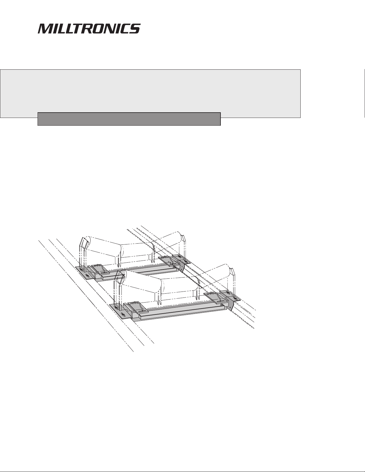
ABOUT THE MMI-2
The Milltronics Multiple Idler (MMI-2) is a belt scale application using two Milltronics Single Idler (MSI) belt
scales in succession. The scales are designed to be inserted into belt conveyors for continuous weighing of
dry bulk solids.
Each MSI is comprised of the following: - one weighbridge c/w two load cells with cables run in a
common flexible conduit
- test weight(s)
The addition of an idler (supplied and installed by customer) to each weighbridge completes th e weighing
assembly. The MMI load cells provide an electronic signal, proportional to load, which is fed to the Milltronics
CompuScale series integrator. Thus, weighing is accomplished without disturbing the process and without
affecting the process material.
The MMI-2 is used where conveyor belt speeds or belt loading charactistics result in conditions that
necessitate extending the weighing time beyond the capibilities of a single idler scale. It is also well suited for
applications that require higher sustained accuracies, such as production control inventory accountability or
where certification for trade purposes is required.
It is important to understand that the MMI-2 is an accurate and repeatable force sensor. Its performance is
ultimately dependent upon the conveyor system and the quality of the installation and alignment.
PL-327 1
Page 5

SPECIFICATIONS
Accuracy: » ± 0.25% of totalization over 5 to 1 operating range
in factory approved installations
Belt Width: » 18" to 96" in CEMA sizes
» 500 to 2000 mm in metric sizes
» refer to Outline and Dimensions
Belt Speed: » up to 4 m/s (800 fpm)
Capacity: » up to 5000 TPH at maximum belt speed
Conveyor Incline: » ± 20° from horizontial, fixed incline
» up to ± 30° with reduced accuracy
Conveyor Idler: » flat to 35°
» up to 45° with reduced accuracy
Idler Diameter: » 50 to 180 mm (2 to 7")
Idler Spacing: » 0.5 to 1.5 m (1.5 to 5.0 ft)
Load Cell: » excitation: » 10 V DC nominal
» 15 V DC maximum
» output: » 2 mV / V excitation at rated load cell capacity
» non-linearity: » 0.02% of rated output
» hysteresis: » 0.02% of rated output
» non-repeatability: » 0.01% of rated output
» capacity: » maximum ranges: 50, 100, 250, 500, 750,1000 lb
» overload: » maximum 1000% of rated capacity
» temperature: » – 40 to 85 °C (– 40 to 185 °F) operating range
» – 15 to 65 ° C ( 5 to 150 °F) internally compensated
Approvals: › CSA certified for general purpose
Hazardous Locations: › with the use of approved intrinsically safe barrier strips
Weight: › see chart, Outline and Dimensions
PL-327 2
Page 6
OPERATION
Each MSI weighbridge is designed to react to the vertical component of the force being applied to it. Each MSI
consists essentially of a static assembly and a weighing assembly.
The static assembly is used to mount each MSI between the conveyor stringers and supports the weighing
assembly via its load cells.
The weighing assembly supports the scale idler and transfers the weight of the material to the load cells.
These are the active components in the weighing assembly.
As the material travels along the conveyor, a force is exerted through the suspended idler onto the weighing
assembly. The weighing assembly is forced down proportionally. The movement in each load cell is sensed
by its strain gauges. These modulate the excitiation signal from the electronic integrator to produce a signal
proportional to weight, which is returned to the integrator. The movement in the load cell is limited by the
positive stop incorporated in the design of the load cell.
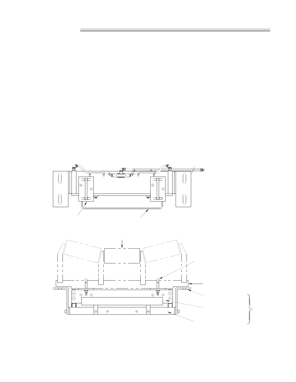
idler bracket
test weight bar
Force
idler clip
idler frame
scale mounting bracket
dynamic beam
static beam
weigh
bridge
PL-327 3
Page 7

INSTALLATION
PREAMBLE
The MMI-2 is shipped from the factory, attached to a frame for protection. Each MSI weighbridge must be
removed from its shipping frame and inspected for physical damage.
Insure that the conveyor design meets the installation requirements for the Milltronics MMI-2 scale. The
conveyor stringers must be rigid, straight, parallel to and square with the belt line in the area of the scale
installation. The idlers to be used on the scale and at least the next two approach and retreat idlers must be
of the same style and manufacture and in good condition.
Prepare the site in accordance with the Milltronics drawing(s) provided or by reference to Milltronics
instruction manual PL-328, Applications Guidelines.
WELDING
Extreme caution should be used when arc welding in the area of the belt scale. Insure that no welding current
can flow through the belt scale. Welding currents through the scale are sufficient to functionally destroy the
load cells.
LOAD CELL HANDLING
The load cell can tolerate very little negative displacement, otherwise the load cell will be functionally destroyed.
When handling the individual MSI’s install both shipping stops to their vertical position to protect the load cells.
Do not lift the MSI’s by the weighing assembly or subject it to shock from blows of a hammer when trying to
position it.
DO NOT STAND OR WALK ON THE SCALE.
OVERLOADING, SHOCK AND TWISTING OF THE SCALE CAN ALL
FUNCTIONALLY DESTROY THE LOAD CELLS.
PL-327 4
Page 8

INSTALLATION PROCEDURE
1. Remove the conveyor idlers currently at the desired points of installation.
2. Remove the foot plates and modify the idler frame at both ends of the idlers as shown .
customer’s idler
12.7 mm
(0.5")
100 mm
(4")
before
after
3. Insert the MSI’s in the place of the removed idlers. The MSI is designed to use the existing holes in the
stringer and should not require further drilling. Install the mounting bolts and nuts, but do not tighten .
Remove the idler clips. Refer to Outline and Dimensions.
location of
removed idlers
material flow
test weight(s)
test weight(s)
MSI belt scales
Insure that there is sufficient clearance between the return belt and the MSI and test weight (when used
during the calibration procedure).
PL-327 5
Page 9

4. Position the individual MSI’s such that they are centered and square to the stringer. Mount the modified
idlers such that they are centered onto the scale using the idler clips. Tighten all mounting hardware.
Refer to Idler Mounting for alternate idler mounting arrangements.
Orient the scale so that the large arrow on the scale mounting brackets is pointing in the direction
of material flow.
idler clips
conveyor stringer
(typical)
5. Release the shipping stops on each MSI in order to free the weighing mechanism. Loosen screws ‘A’ and
rotate both shipping stops inward until the underside slots slide around the shoulder bolts ‘B’. Tighten
screws ‘A’ to secure in place.
‘A’ screws
shipping stop
‘B’ shoulder bolts
PL-327 6
shipping stop
Page 10

6. The idlers in the weighing area must be properly aligned and leveled by shimming the scale idler (S#), the
two approach (A#) and the two retreat idlers (R#) until they are within ± 0.8 mm (1/32") of each other.
Be sure to check that the idlers are centered and squared to the conveyor during the shimming process.
Center of
idlers to
be in line
90°
CC
idlers must be square to stringers
R 1
R 2
alignment of idlers
A 2 to R 2 to be within
±
0.8 mm (1/32")
A 2
material flow
S 1
S 2A 1
7. Precise idler alignment is very important if maximum accuracy of the weighing system is to be achieved.
Misaligned idlers will result in unequal forces being applied on each idler in the weighing area, causing
calibration and measurement errors. Use a good quality wire or string to check for alignment. The wire
or string must be able to withstand sufficient tension as to eliminate any sag. By shimming, make the
necessary adjustments to bring all the rolls of the A2 through to the R2 idlers in line within 0.8 mm(1/32").
A 2
approach idlers
A 1
S 1
S 2
MSI with modified scale idler
wire or string
(for alignment)
PL-327 7
R 1
retreat idlers
R 2
Page 11

Although the accepted tolerance for idler alignement is ±0.8 mm (1/32"), the scale mounted idlers should
never be lower than the adjacent idlers. Establishing good idler alignment is the most important part of the
installation procedure. Scale accuracy is directly affected by alignment. Proper attention must be given here.
CALIBRATION
GENERAL
After the MMI-2 has been properly installed, calibration of the weighing system must be done in conjunction
with the integrator. Refer to the integrator instruction manual for programming and calibration. The
calibration is initially done using the supplied test load. Material tests are recommended to achieve maximum
accuracy.
TEST LOAD
The test load value for each MSI is the same and is given on the accompanying data sheet. The value is to
be entered into the dedicated programming parameter of the integrator, in kilograms per meter or pounds per
feet. An equal number and mass of weights must be applied to each suspension during the span calibration
function.
If the actual idler spacing differs from that recorded on the design data sheet, the test load must be
recalculated as follows. Failure to do so will cause the design test load value to be in error.
test load = total weight of all test weights per MSI kg lb
idler spacing m ft
ZERO
Perform the zero calibration as described in the Calibration section of the integrator manual.
SPAN
The test load used in the calibration procedure is the two sets of test weights ( 1 to 12 ) supplied, one for each
MSI suspension.
Place each set of the test weights onto the calibration weight bar of the respective MSI as shown.
Perform the span calibration as described in the Calibration section of the integrator instruction manual.
After the span calibration has been completed, remove the test load and store it.
( )
OR
( )
MSI
PL-327 8
test weight(s)
Page 12

MATERIAL TEST
The MSI is guaranteed to be accurate to ±0.25% when installed on a conveyor in accordance with this manual
and meeting the qualifications outlined in Manual PL-328 "MMI Applications Guidlines". This guarantee is
based on calibrations performed using the test weights furnished with the scale and as previously referenced.
When the existing conditions are such that the installation of the scale cannot meet the above mentioned
requirements for an approved installation it is recommended that material tests be performed. This will enable
the user to compare the present scale results to the results of the material tests. The scale is then adjusted or
factored so that subsequent scale calibrations with test weights will agree with actual run of material.
At least 3 samples of a minimum of 10 minutes duration at normal capacity should be taken to insure
repeatability. Refer to "Material Test" and subsequent "Factoring" sections of the integrator manual.
RE-RATING
Any significant change in rate, speed and /or idler spacing from original design specifications should be
referred to your local Milltronics office to insure that proper design parameters are maintained.
MAINTENANCE AND SPARE PARTS
Each weighbridge should be kept clean. Accumulations of material between the weighing assembly and
static assembly as well as around each load cell can be detrimental to the weighing accuracy.
Periodically check the mechanical integrity of the scale and alignment of the stringers and idlers within the
weighing area.
The integrity of the load cells can be seen when zero and span calibrations are performed. If the zero and
span deviations display a continuous unidirectional drift or the system becomes uncalibratable for no apparent
mechanical reason, the load cells may be suspect.
Replacement of load cell(s) will require a re-balancing of the load cells. Refer to the load cell balancing
procedure for four load cells in the integrator manual.
The only spare part recommended for the MSI is the load cell. Refer to the load cell nameplate for the proper
size and model number.
Precautions :
» when arc welding near the scale do not allow current to pass through the belt scale.
» reset the shipping stops to reduce physical shock to the load cells during maintenance.
» recalibrate after maintenance and prior to use.
PL-327 9
Page 13

IDLER MOUNTING
The MSI is usually installed in conveyors employing conventional rigid structure idlers. Within this type of
idler, construction will vary depending on the manufacture and the application. The idler depicted in the
Installation Procedure uses an angle iron spine. The following depicts alternate idler construction and tips on
how they should be modified and installed.
TROUGHED IDLER WITH CHANNEL SPINE
gusset reinforcement
if required, see
Installation Procedure
customer’s idler
12.7 mm
(0.5")
foot pads welded
to idler spine
before after
100 mm
(4")
idler modification
idler clip
idler installation
PL-327 10
customer bolts
(4 places)
Page 14

TROUGHED IDLER WITH PIPE SPINE
customer’s idler
12.7 mm
(0.5")
foot pads welded
to idler spine
before after
100 mm
(4")
idler modification
idler clip
idler installation
PL-327 11
customer bolts
(4 places)
Page 15

FLAT IDLER
customer’s idler
before after
in most applications standard
conveyor manufacturers’
brackets cannot be used,
replacement brackets
(as shown) are needed
12.7mm
(0.5")
idler modification
customer bolts
(4 places)
idler installation
PL-327 12
idler clip
Page 16

MMI-2 WIRING
load cell ‘A’ (‘C’)
see detail ‘A’
load cell ‘A’
MSI #2
belt travel
MSI #1
load cell ‘B’ (‘D’)
load cell ‘B’
DETAIL ‘A’
conduit and connector
load cell
‘A’
+
E
X
E
–
E
X
E
MSI #1
–
+
S
S
I
I
G
G
A
A
to integrator
belt travel
load cell
‘B’
load cell
‘A’
MSI #2
load cell
‘B’
customer
junction
box
–
+
–
S
S
S
I
G
B
H
I
I
G
E
L
B
D
–
+
E
E
X
X
E
E
+
S
S
I
I
G
G
A
A
+
–
S
I
G
B
S
S
H
I
I
G
E
L
B
D
to integrator
PL-327 13
Page 17

OUTLINE DIMENSIONS - CEMA
‘C’
178 mm
(7")
‘D’
‘A’
‘B’
conveyor mounting scale minimum drop-in ‘C’ ‘D’ weight
belt width width ‘A’ width ‘B’
18 " 27 " 24.5 " 9.5 " 5.5 " 82 lb
20 " 29 " 26.5 " 9.5 " 5.5 " 85 lb
24 " 33 " 30.5 " 9.5 " 5.5 " 90 lb
30 " 39 " 36.5 " 9.5 " 5.5 " 99 lb
36 " 45 " 42.5 " 9.5 " 5.5 " 107 lb
42 " 51 " 48.5 " 9.5 " 5.5 " 116 lb
48 " 57 " 54.5 " 12 " 8" 162 lb
54 " 63 " 60.5 " 12 " 8" 174 lb
60 " 69 " 66.5 " 12 " 8" 185 lb
72 " 81 " 78.75 " 12 " 8" 235 lb
84 " 93 " 90.75 " 12 " 8" 261 lb
96 " 105 " 102.75 " 12 " 8" 288 lb
PL-327 14
Page 18

LINE DIMENSIONS - METRIC
‘C’
178 mm
(7")
‘D’
‘A’
‘B’
conveyor mounting scale minimum drop-in ‘C’ ‘D’ weight
belt width width ‘A’ width ‘B’
500
650
800
800
1000
1000
1200
1200
1400
1600
1800
2000
mm
mm
mm
mm
mm
mm
mm
mm
mm
mm
mm
mm
740
mm
890
mm
1040
mm
1090
mm
1240
mm
1290
mm
1450
mm
1540
mm
1650 / 1740
1900 / 1940
2100 / 2140
2300 / 2340
mm
mm
mm
mm
677
mm
827
mm
977
mm
1027
mm
1177
mm
1227
mm
1387
mm
1477
mm
1587 / 1677
1837 / 1877
2037 / 2077
2237 / 2277
mm
mm
mm
mm
241
241
241
241
241
305
305
305
305
305
305
305
mm
mm
mm
mm
mm
mm
mm
mm
mm
mm
mm
mm
140
140
140
140
140
203
203
203
203
203
203
203
mm
mm
mm
mm
mm
mm
mm
mm
mm
mm
mm
mm
37 kg
40 kg
44 kg
48 kg
52 kg
73 kg
78 kg
83 kg
88 kg
93 kg
98 kg
103 kg
PL-327 15
Page 19

Siemens Milltronics Process Instruments Inc.
1954Technology Drive, P.O. Box 4225
Peterborough, ON.Canada K9J 7B1
Tel: (705) 745-2431 Fax: (705) 741-0466
www.milltronics.com
c
Siemens Milltronics Process Instruments Inc. 2001
Subject to change without prior notice
*7ML19981dr01*
Printed in Canada
 Loading...