

Page 1

MD-36 SPEED SENSOR
Instruction Manual PL-392 January 2001
Instruction Manual PL-342 August 2001
33453420
Rev. 3.4
Page 2

Safety Guidelines
Warning notices must be observed to ensure personal safety as well as that of others, and to protect the pr oduct and the connected equipment.
These warning notices are accompanied by a clarification of the level of caut ion to be observed.
Qualified Personnel
This device/system may only be set up and operated in conjunction with this manual. Qualified personnel are only authorized to install and
operate this equipment in accordance with established safety practices and standards.
Warning
Note
This product can only function proper ly and safely if it is correctly transported, stored, installed, set up , operated, and maintained.
:
Always use product in accordance with specifications.
:
Copyright Siemens Milltronics Process
Disclaimer of Liability
Instruments Inc. 2000. All Rights Reserved
This document is available in bound version and in
electronic version. We encourage users to purchase
authorized bound manuals, or to view electronic versions as
designed and authored by Siemens Milltronics Process
Instruments Inc. Siemens Milltronics Process Instruments
Inc. will not be responsible for the contents of partial or
whole reproductions of either bound or electronic versions.
MILLTRONICS®is a registered t r ad emark of Siemens Milltronics Process Instruments Inc.
While we have verified the contents of this
manual for agreement with the instrumentation
described, variations remain possible. Thus we
cannot guarantee full agreement. The content s of
this manual are regularly reviewed and
corrections are included in subsequent editions.
We welcome all suggestions for impr ovement .
Technical data subject to change.
Contact SMPI Technical Publications at the following address:
Technical Publications
Siemens Milltronics Process Instruments Inc.
1954 Technology Drive, P.O. Box 4225
Peterborough, Ontario, Ca nad a, K9J 7B1
Email: techpubs@milltronics.c om
For the library of SMPI instruction ma nuals, visit our Web site:
© Siemens Milltronics Process Instruments Inc. 2001
www.milltronics.com
Page 3

SPECIFICATIONS
Power: - +15 V dc, 25 mA from integrator
Temperature: - -40 to 55° C (-40 to 130°F)
Input: - shaft rotation 0 to 1,000 rpm, bidirectional
Output: - open collector sinking output, max. 25 mA at 15 V dc
- 36 pulses / revolution
- 0 to 1,000 rpm = 0 to 600 Hz
Input:output: - 1:1 (speed ratio)
Enclosure: - MD-36 : aluminum
rating: Type 4/NEMA 4/IP 65
- MD-36A : aluminum
- MD-36SS : 304 stainless steel
Approval: - MD-36 - CSA & FM : class II, GR. E, F&G, class III
Cable (optional): - Belden 8770, 3 wire shielded, 18 AWG or equivalent
- max run 305 m (1000 ft)
REFERENCE
Associated equipment: Milltronics integrator
Compuscale
Compuscale II
Compuscale IIA
Compu-M
Compuscale III
Accumass BW 100
Accumass BW 500
GENERAL
The MD-series speed sensor is used to monitor the speed of a belt conveyor. The sensor, coupled to the
motor or pulley shaft, converts the rotation of its input shaft into an encoded speed signal. The speed
signal is transmitted to the integrating electronics for use in computing the rate of material flow.
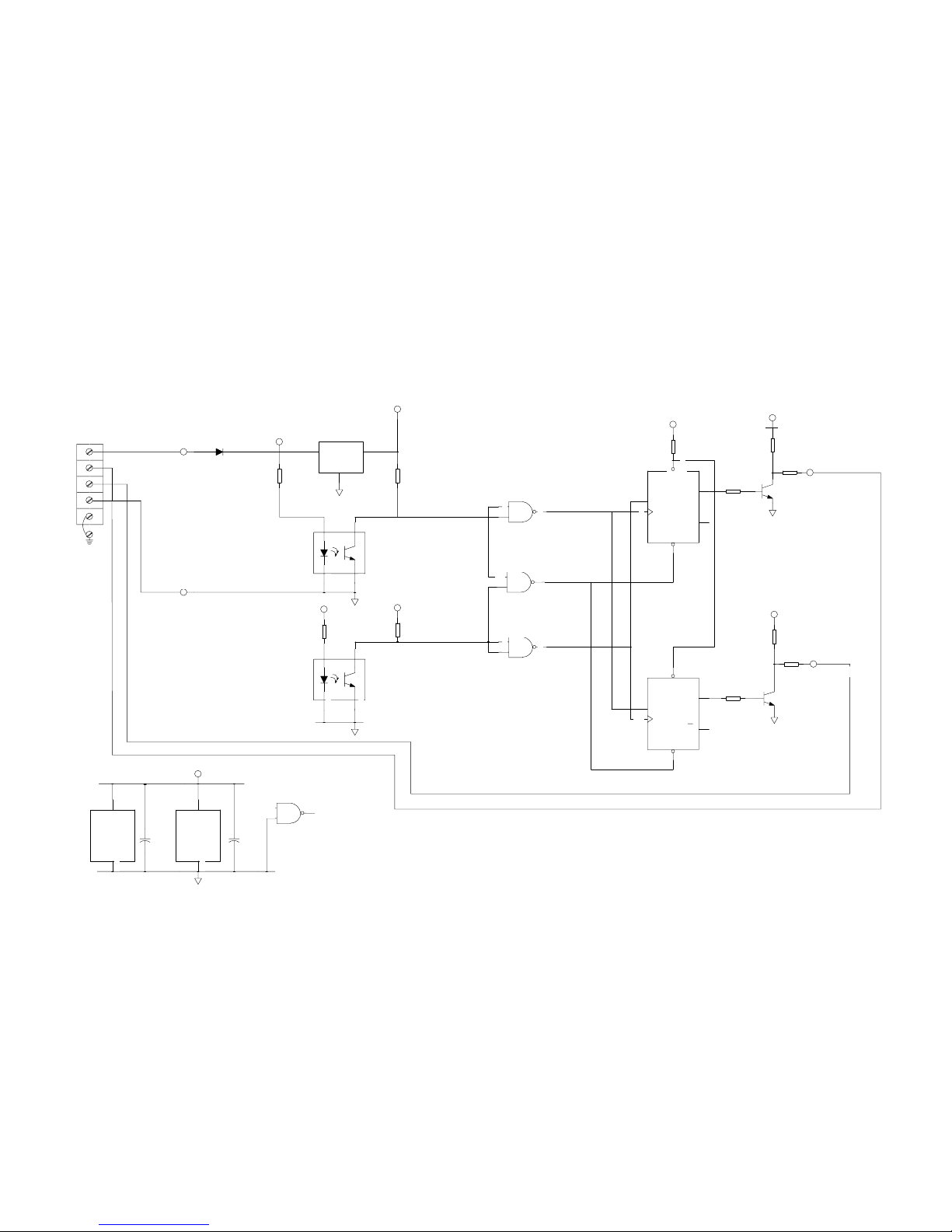
CIRCUIT OPERATION
The speed sensor is made up of a main shaft rotating in a bearing assembly fixed to the enclosure. The
shaft turns a toothed disk, which is divided into 36 teeth each separated by a gap equal to the tooth width.
The encoder card is mounted such that the two optocouplers straddle the disk’s teeth.
( Refer to FIG. 5 )
Power from the integrating de vice i s used to energize the two optocoupler LED’s and to feed the 5V dc
regulator. The 5V dc bus powers the logic circuitry and the output driver transistors.
As the shaft is rotating, the 36 toothed wheel modulates the light crossing within each optocoupler (O C1
and OC2). The resulting outputs are two 50% duty cycle square waves that are phase shifted by 90
degrees electrical or 1/4 cycle (one cycle of 360 degrees electrical corresponds to the width of one tooth
and one gap). This configuration provides directional discrimination.
PL-342 1
95/01/03
Page 4

The optocouplers’ square wave outputs are converted into CW and CCW square wave output signals by
the intermediate logic. When the shaft rotates in a CW direction, the logic produces pulses at the CW
output (1RC 2) and the CCW output is disabled. When the shaft rotates in a CCW direction, the logic
produces pulses at the CCW output (1RC 4) and the CW output is disabled.
The logic diagrams detail the operation of the electronics for both the clockwise and counterclockwise
output generation.
The speed sensor is immune to external vibration that would cause the toothed wheel to oscillate 1/4
cycle (1/2 tooth width or 5° of shaft rota tion) or less.
MOUNTING
The MD-36 speed sensor c an be coupled to a tail pulley, bend pulley or motor shaft. In the general
(floating) mounting arrangement, the input shaft and bearing assembly bear the weight of the speed
sensor. The unit’s arresting bracket stops the speed senso r from rotating with the shaft.
When mounting the speed sensor, ensure that the shaft alignment is true to avoid stresses on the
shaft bearing.
Mounting Reference Drawings:
MD-36 Pulley Mounting Figure 2
MD-36 Motor Shaft Mounting Figure 3
For preferred mounting locations, refer to the as sociated belt scale or weigh feeder instruction manual.
INTERCONNECTION
ALL WIRING MUST BE DONE IN CONJUNCTION WITH APPROVED
CONDUIT, BOXES AND FITTINGS AND TO PROCEDURES
IN ACCORDANCE WITH ALL GOVERNING REGULATIONS.
Interconnection between the speed sensor and the integrator should be made with 3 wire shielded, 18
AWG cable (Belden 8770 or equivalent).
Ground the shield at the integrator ONLY!
FLEXIBLE CONDUIT IS RECOMMENDED SO EXCESS STRESS
IS NOT APPLIED TO THE SHAFT BEARINGS.
PL-342 2
95/01/03
Page 5

SPEED SENSOR INTERCONNECTION
MD-36 C
Description Terminal
ompuscale Compu II Compu IIA C om pu - M Compu III
to 1 TB to 1 TB to 1 TB to TB1 to TB1 to TB1 to TB1
ccumass
A
BW 100
Accumass
BW 500
+ 15 V dc 1 1 15 12 11 30 8 19
speed
2 (2) (16) (13) (12) (31) (7) (16)
out-CW
speed
3 (2) (16) (13) (12) (31) (7) (16)
out-CCW
Common 4 4 17 14 13 32 6 17
Ground G N/C N/C N/C N/C N/C N/C N/C
Terminal positions in brackets denote that only one signal may be connected at one time. To determine
direction of rotation refer to Figure 3
‘ N/C ’ denotes ‘ no connection ’
MAINTENANCE
The speed sensor electronics normally requires no maintenance, however a program of periodic checks
would be beneficial. The enclosure and circuit board should be cleaned if necessary, but only when the
power is disconnected using a vacuum cleaner and a clean dry paint brush. Check all electrical contacts
for corrosion and arcing.
The speed sensor bearing should be periodically checked for corrosion, wear and seizing. The bearing‘s
life is dependent upon the mounting, the severity of the application and surrounding environment.
PL-342 3
95/07/05
Page 6

Page 7
TRONICSMILL
TRONICS
MILL
( ref. )
61 mm
( 2.4")
213 mm
( 8.4" )
112 mm
( 4.4" )
16 mm ( 0.63" )
Ø shaft
114 mm
( 4.5" )
117 mm
( 4.6" )
124 mm
( 4.9" )
6mm ( 0.25" )
Ø shaft
(2 places)
61mm
( 2.4" )
142 mm
( 5.6" )
71 mm
( 2.8" )
218 mm
( 8.6" )
142 mm
( 5.6" )
71mm
( 2.8" )
21 mm
( 0.8" )
84 mm
( 3.3" )
56 mm
( 2.2" )
1/2 NPT plug
(2 places )
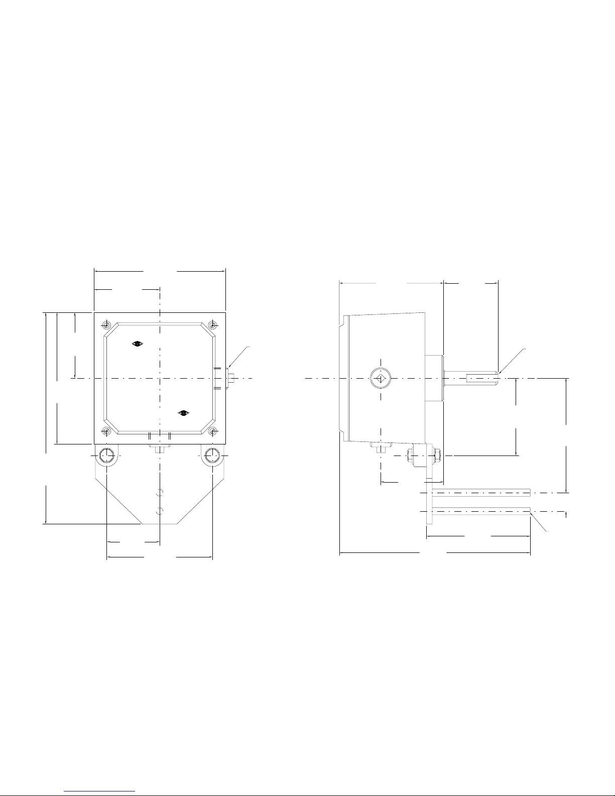
FIG. 1
MD - 36/36A OUTLINE
92/12/08
Page 8

( ref. )
76 mm
( 3" )
216 mm
( 8.5" )
102 mm
( 4" )
16 mm ( 0.63" )
Ø shaft
114 mm
( 4.5" )
127 mm
( 5" )
86 mm
( 3.4" )
6 mm ( 0.25" )
Ø shaft
(2 plac es)
61 mm
( 2.4" )
152 mm
( 6" )
76 mm
( 3" )
239 mm
( 9.4" )
152 mm
( 6" )
19 mm
( 0.75" )
21 mm
( 0.8" )
38 mm
( 1.5" )
51 mm
( 2" )
FIG. 1A
76 mm
( 3" )
cable connector
for 3 to 9 mm (.12 5"
to .25") o.d. cable
127 mm
( 5" )
MD - 36 SS OUTLINE
Page 9

Floating
MD - 36 SERIES PULLEY MOUNTING
see DETAIL ’A’
pulley
shaft
spring
’B’
MD - 36
series
127 mm
(5")approx.
secure with
hook or bo l t
anti rotation sp ring
5/16-18 UNC
set screw
( by customer )
DETAIL ‘A’
64 mm
(2.5")
25 mm
(1")
16 mm (.63 0" )
16.07 mm( .633 " )
.254mm(.010")
A
angle iron
(by cust o m er )
DIA.
A
’B’
arresting bracket (by Milltronics)
shorten if required, refer to cross
sectio n ‘ B - B’
arresting bracket
CROSS SECTION ‘B-B’
NOTE :
1. Machining on tail/bend pulley shaft per Detail ’A’ (by customer) to accommodate Milltronics speed sensor when
tail or bend pulley is not supplie d by Milltronics.
angle
iron
2. Arresting bracket is an anti-rotation device only and must not secure or support the speed sensor. Bearing life would
be greatly reduced if speed sensor is not free to "float". Use anti-rotation spring to prevent mechanical oscillation of
speed sensor.
3. Grease mating surfaces to prevent seizing.
FIG. 2
95/07/05
Page 10

C
W
C
C
W
refer to
outline
drawing
0.8 mm (0.313" )
2 places
FIG. 3
16 mm ( 0.63" )
Ø shaft
motor shaft
customer mounting bracket
( remove arresting bracket supplied )
13 mm
( 0.5" )
optimum
dimension
guard
(to suit)
MD - 36
series
rubber hose
hose clam p (typ)
motor
0.8 mm (0.03" )
max shaft offset
shaft rotation
MD - 36 SERIES MOTOR SHAFT MOUNTING
Fixed
Page 11
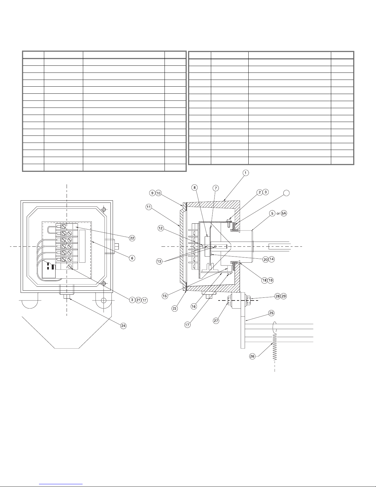
MD - 36/36A PARTS IDEN TIFICAT ION
ITEM PART No. DESCRIPTION QTY.
1 54000923 Enclosure 1
2 32900200 Screw, 6-32 x 5/16 3
3 32950135 External Lockwasher #6 5
4 22600 00 5 Gasket, Bearing Assembly 1
5 23250 09 9 MD-3 6 Bea r ing As sembly 1
5A 23250147 MD-36A Bearing Assembly
6 21550 01 6 MD-3 6 Shr o ud 1
7 20300 07 5 Disc 36 Tooth 1
8 20300 055 Disc Hub 1
9 32900480 Slot Round Head Screw 1/4" 4
10 32950100 Lockwasher Split 1/4" 4
11 45000061 Enclosure Cover 1
12 25500060 Extension Shaft 1
13 32900560 Set Screw Socket, 8-32 x 3/16 2
14 32950130 External Lockwasher #4 3
15 20550025 Bushing 2
G
4
3
2
1
ITEM PART No. DESCRIPTION QTY.
16 51016921 Speed Pickup Card Ver.3 1
17 32900212 Binding Screw, Slot, 6 - 32 x 5/8 4
18 32900878 Cap Screw, Socket, 10 - 32 4
19 32950095 Lockwasher, Split #10 4
20 32900085 Binding Screw, Slot, 4 - 40 3
21 32850030 Hex Nut, 6 - 32 2
22 26000130 Terminal Block CSA 1
23 22600008 Gasket, Cover 1
24 24700015 Threaded Plug, 1/2 NPT 2
25 20500008 Enclosure Arresting Bracket 1
26 25700025 Spring Spnr. B-604 1
27 32800065 Bolt, Hex 5/ 16 - 18 x 1 1/4 2
28 32850055 Nut, Hex 5/16 - 18 2
29 32950040 Washer, Flat 5/16 2
30 32950105 Lockwasher Split 5/16 2
P/N
MD-
Bearing Assembly Replacement
- turn supply power from integrator off
- remove speed sensor from mounting
- remove cover #11 and the 4 bearing assembly mounting screws #18 located externally around shaft
- pull out bearing assembly #5 c/w card, disc hub, disc and mounting brackets
- remove screws #17, bushing #15 and card #16
- remove speed sensor shroud screws #2
- loosen hex screw in shaft and remove extension shaft, disc hub and disc
- bearing assembly is now free
FIG. 4
Page 12

MD - 36 SS PARTS IDENTIFICATION
ITEM PART No. DESCRIPTION QTY.
1 54000050 Enclosure 1
2 32900200 Screw, 6 - 32 x 5/16 3
3 32950 13 5 E x ter nal Lockwas he r , #6 5
4 22600005 Gasket, Bearing Assembly 1
5 A32 50101 Beari ng A ss em bly 1
6 21550 01 6 MD-36 Shr o ud 1
7 20300 07 5 Disc 36 T o oth 1
8 20300 055 Disc Hub 1
9 25500060 Extension Shaft 1
10 329005 60 Set Screw Socket, 8- 32 x 3/16 2
11 32950130 External Lockwasher #4 3
12 20550025 Bushing 3
13 51016921 Speed Pickup Card Ver.3 1
G
4
3
2
1
ITEM PART No. DESCRIPTION QTY.
14 32900212 Binding Screw, Slot, 6 - 32 x 5/8 4
15 32900471 SS Screw, Socket, 10 - 32 x 1/2 4
16 32950096 Lockwasher, Split, #10 SS 4
17 32900085 Binding Screw, Slot, 4 - 40 x 3/8 3
18 328500 30 Hex Nut, 6 - 3 2 2
19 26000130 Terminal Block 1
20 A1400087 Cable Connector 1
21 A0500009 Enclosure Arresting Bracket 1
22 32850120 Locknut T&B 1/2 in # 141 1
23 25700025 Spring Spnr. B-604 1
24 32800056 Bolt, Hex 5/16 - 18 x 3/4 SS 2
25 32950041 Washer, Flat 5/16 SS 2
26 32950106 Lockwasher, Split 5/16 SS 2
27 32850056 Nut, Hex 5/16 - 18 NC SS 2
MD-
P/N
Bearing Assembly Replacement
- turn supply power from integrator off
- remove speed sensor from mounting
- open cover and remove the 4 bearing assembly mounting screws #15 located externally around shaft
- pull out bearing assembly #5 c/w card, disc assembly and MD - 36 shroud
- remove screws #14, bushing #12 and card #13
- remove MD - 36 shroud screws #2 and MD - 36 shroud c/w terminal block #19 and card #13 attached
- loosen hex screw in shaft and remove extension shaft, disc hub and disc
- bearing assembly is now free
FIG. 4A
Page 13
ref.10C 1295 R2
GRN
WHT
BLU
CCW
SPEED OUT 2
CW
SPEED OUT 1
STRIP
TERMINAL
CHASSIS
G
4
3
2
1
D COM
+15 V
4
1RC
2
1RC
P5V
R7
10K
R6
499
Q2
2N4401
R8
10K
R5
499
R9
10K
P5V
R11
10K
R10
10K
C2
.1MFD
C1
.1MFD
BLK
RED
3
1
D1
1N4005
51016921
ML
P5V
Q1
2N4401
P5V
P15V
P5V
P15V
R4
10K
R2
1K
R3
10K
R1
1K
P5V
D2
CLK 2
CLR 2
Q2
Q2
PR 2
IC3
74LS74
12
11
13
8
9
10
IC2
74HCT132
12
13
11
COM
V+
IC3
74LS74 14
7
D1
CLK 1
PR 1
CLR 1
Q1
Q1
IC3
74LS74
2
3
1
6
5
4
COM
V+
IC2
74HCT132 14
7
IC2
74HCT132
4
5
6
IC2
74HCT132
9
10
8
IC2
74HCT132
1
2
3
OC2
H21A1
1
2 4
3
OC1
H21A1
1
2 4
3
IN OUT
COM
IC1
MC78L05
Note: Chassis terminal strip, customer connection to integrator.
Refer to associated integrator manual for interconnection wiring.
FIG. 5
MD - 36 SE RIE S S CHE MAT IC
Page 14

OC1 pin 3
OC2 pin 3
IC2 pin 3
IC2 pin 6
Logic D iagrams
CW & CCW oper ation
clockwise counterclockwise
IC3 pin 8
IC3 pin 5
IC3 pin 9
1RC 2
Speed Out
CW
1RC 4
Speed Out
CCW
FIG. 5A
Page 15

Siemens Milltronics Process Instruments Inc.
1954Technology Drive, P.O. Box 4225
Peterborough, ON.Canada K9J 7B1
Tel: (705) 745-2431 Fax: (705) 741-0466
www.milltronics.com
c
Siemens Milltronics Process Instruments Inc. 2001
Subject to change without prior notice
*7ML19981DB01*
Printed in Canada
 Loading...