

Page 1
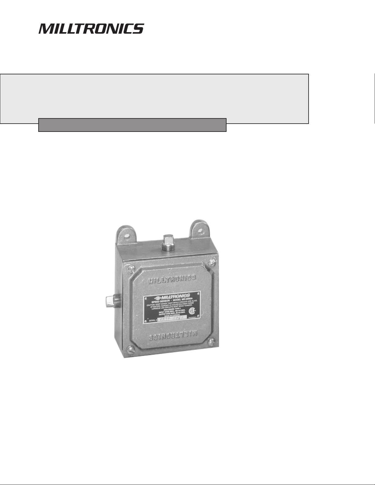
MD-2000A SPEED SENSOR
Instruction Manual June 2002
Page 2

Safety Guidelines
Warning notices must be observed to ensure personal safety as well as that of others, and to protect the product and the connected equipment.
These warning notices are accompanied by a clarification of the level of caution to be observed.
Qualified Personnel
This device/system may only be set up and operated in conjunction with this manual. Qualified personnel are only authorized to install and
operate this equipment in accordance with established safety practices and standards.
Warning: This product can only function properly and safely if it is correctly transported, stored, installed, set up, operated, and maintained.
Note: Always use product in accordance with specifications.
Copyright Siemens Milltronics Process
Disclaimer of Liability
Instruments Inc. 2002. All Rights Reserved
This document is available in bound version and in
electronic version. We encourage users to purchase
authorized bound manuals, or to view electronic versions as
designed and authored by Siemens Milltronics Process
Instruments Inc. Siemens Milltronics Process Instruments
Inc. will not be responsible for the contents of partial or
whole reproductions of either bound or electronic versions.
MILLTRONICS®is a registered trademark of Siemens Milltronics Process Instruments Inc.
While we have verified the contents of this
manual for agreement with the instrumentation
described, variations remain possible. Thus we
cannot guarantee full agreement. The contents of
this manual are regularly reviewed and
corrections are included in subsequent editions.
We welcome all suggestions for improvement.
Technical data subject to change.
Contact SMPI Technical Publications at the following address:
Technical Publications
Siemens Milltronics Process Instruments Inc.
1954 Technology Drive, P.O. Box 4225
Peterborough, Ontario, Canada, K9J 7B1
Email: techpubs@milltronics.com
For the library of SMPI instruction manuals, visit our Web site:
© Siemens Milltronics Process Instruments Inc. 2002
www.siemens-milltronics.com
Page 3

SPECIFICATIONS
Power: » +15 V dc, 150 mA from integrator
Temperature: » -20 to 55° C (-4 to 130° F)
Input: » bi-directional shaft rotation
» 0.3 to 75 rpm operating input
Output: » open collector sinking output, max. 25 mA at 5 V dc
» 2048 pulses / revolution
» 10 to 2,560 Hz operating output
Enclosure: » general purpose
» material : - standard : aluminum
- optional : 304 stainless steel
Cable: » Belden 8770, 3 wire shielded, 18 AWG or equivalent
» max run 305 m (1000 ft)
REFERENCE
Associated Milltronics integrator:
CompuScale III
BW100
BW500
GENERAL
The MD-2000A speed sensor is used to monitor the speed of a weighfeeder or low speed belt conveyor ( see
input specification ). The sensor, coupled to a pulley shaft, converts the rotation of its input shaft into an
encoded speed signal. The speed signal is transmitted to the integrating electronics for use in computing the
rate of material flow.
CIRCUIT OPERATION
The speed sensor is made up of a main shaft rotating in a bearing assembly fixed to the enclosure. The shaft
turns an encoder which produces two square wave quadrature (90° electrically out of phase) outputs which
are fed to the speed sensor board to determine direction of rotation as well as the speed of rotation.
Power is provided by the integrating device. The 15 V dc supply is regulated to 5 V dc for use by the encoder
circuit and output drive transistors of the speed sensor board.
As the shaft rotates, the two quadrature square waves from the 2048 pulse per revolution encoder are
converted into clockwise (CW) and counter clockwise (CCW) square wave output signals by the intermediate
counter logic. When the shaft rotates in the CW direction, the logic produces pulses at the CW output and the
CCW output is disabled. When the shaft rotates in the CCW direction, the logic produces pulses at the CCW
output and the CW output is disabled.
The logic diagrams detail the operation of the electronics for both clockwise and counter clockwise output
generation. The speed sensor is immune to external vibration that would cause the encoder to oscillate 1/8 of
a revolution or less.
PL-361 1
Page 4

MOUNTING
The MD-2000A speed sensor is usually coupled to the tail pulley shaft of a weighfeeder. On low speed
conveyers, the speed sensor may be coupled to the tail, bend or snub pulley. The mounting arrangement
requires the input shaft and bearing assembly to bear the weight of the speed sensor. The unit’s arresting
bracket stops the speed sensor from rotating with the shaft.
When mounting the speed sensor, ensure that the shaft alignment is true to avoid stresses on the shaft
bearing. Refer to ( MD - 2000A Series Pulley Mounting ).
INTERCONNECTION
ALL WIRING MUST BE DONE IN CONJUNCTION WITH APPROVED
CONDUIT, BOXES AND FITTINGS AND TO PROCEDURES IN
ACCORDANCE WITH ALL GOVERNING REGULATIONS.
Interconnection between the speed sensor and the integrator should be made with 3 wire shielded, 18 AWG
cable (Belden 8770 or equivalent).
Ground the shield at the integrator ONLY!
FLEXIBLE CONDUIT IS RECOMMENDED SO EXCESS STRESS IS NOT
APPLIED TO THE SHAFT BEARINGS.
SPEED SENSOR INTERCONNECTION
MD-2000A BW100 BW500 COMPUSCALE III
DESCRIPTION TERMINAL TO 1TB
+15 V DC(Red) 1 8 19 30
speed out-CW
(White)
speed out-CCW
(Blue)
Common
(Black)
Ground 5 N\C N\C N\C
Terminal positions in brackets denote that only one signal may be connected at one time. To determine
direction of rotation refer to ( MD - 2000A Series Pulley Mounting ).
‘ N/C ’ denotes ‘ no connection ’
2 (7) (16) (31)
3 (7) (16) (31)
4 6 17 32
PL-361 2
Page 5

MAINTENANCE
The speed sensor electronics normally requires no maintenance, however a program of periodic checks
would be beneficial. The enclosure and circuit board should be cleaned if necessary, but only when the
power is disconnected using a vacuum cleaner and a clean dry paint brush. Check all electrical contacts for
corrosion and arcing.
The speed sensor bearing should be periodically checked for corrosion, wear and seizing. The bearings life is
dependent upon the mounting, the severity of the application and surrounding environment.
SPARE PARTS
Bearing Assembly: - MD 2000A
- MD 2000A SS
Speed Sensor Card - without encoder
- with encoder
PL-361 3
Page 6

PL-361
71 mm
( 2.8" )
142 mm
( 5.6" )
MD - 2000A OUTLINE
117 mm
( 4.6" )
61 mm
( 2.4" )
4
218 mm
( 8.6" )
92/12/08
142 mm
( 5.6" )
71 mm
( 2.8" )
56 mm
( 2.2" )
MILL
TRONICS
TRONICS
112 mm
( 4.4" )
MILL
1/2 NPT plug
(2 places)
( ref. )
61 mm
( 2.4")
213 mm
( 8.4" )
114 mm
( 4.5" )
16 mm ( 0.63" )
Ø shaft
84 mm
( 3.3" )
124 mm
( 4.9" )
21 mm
( 0.8" )
6 mm ( 0.25" )
Ø shaft
(2 places)
Page 7

19 mm
( 0.75" )
76 mm
( 3" )
152 mm
( 6" )
MD - 2000A SS OUTLINE
127 mm
( 5" )
61 mm
( 2.4" )
152 mm
( 6" )
239 mm
( 9.4" )
cable connector
for 3 to 9 mm (.125"
to .25") o.d. cable
76 mm
( 3" )
38 mm
( 1.5" )
102 mm
( 4" )
51 mm
( 2" )
( ref. )
76 mm
( 3" )
216 mm
( 8.5" )
114 mm
( 4.5" )
86 mm
( 3.4" )
16 mm ( 0.63" )
Ø shaft
127 mm
( 5" )
21 mm
( 0.8" )
6 mm ( 0.25" )
Ø shaft
(2 places)
Page 8

MD - 2000A SERIES CIRCUIT BOARD LAYOUT
customer connection
to integrator, refer to
associated integrator
manual.
R8
C3 C4
10D775
S3
R1
IC4
RP1
RP3
R9
RP2
J1
J2
R10
C5
IC3
IC2
HS1
C1
IC1
C2
MD2000A
MADE IN CANADA
R6
R7
Q1
Q2
1
1TB
2
D1
R1
3
R2
R3
4
R4
5
R5
PETERBOROUGH,
ONTARIO.
ARLINGTON,TEXAS
WORCESTER,ENGLAND
SN
P15V
CW
(WHT)
CCW
D
COM
GND
(RED)
(BLU)
(BLK)
(GRN)
PN 24751320
ML 51026001
C6
J3
P5V
OV
CN1
A
B
PL-361 6
Page 9

MD - 2000A SERIES PULLEY MOUNTING
see DETAIL ’A’
and note 3
pulley
shaft
spring
5/16-18 UNC
set screw, note 3
( by customer )
64 mm
(2.5")
DETAIL ’A’
25 mm
(1")
16 mm (.630")
16.07 mm( .633" )
A
angle iron
(by customer)
DIA.
A.254mm(.010")
’B’
’B’
MD-2000A
or
MD-2000A SS
arresting bracket (by Milltronics)
shorten if required, refer to cross
section ‘B-B’
127 mm
(5") approx.
arresting bracket
CROSS SECTION ’B-B’
View for
direction
of rotation
secure with
hook or bolt
angle iron
anti-rotation spring
NOTE :
1. Machining on tail pulley shaft per Deta il ’A ’ (by customer) to accomodate Milltronics sp ee d se ns or .
2. Arresting bracket is an anti-rotatio n device only and mu st not secure or support the speed sensor. Bearing life would
be greatly reduced if speed sensor is not free to "float". Use anti-rotation spring to prevent mechanical oscillation of
speed sensor.
3. Grease mating surfaces to prevent seizing.
PL-361 7
Page 10

MD - 2000A PARTS IDENTIFICATION
ITEM DESCRIPTION QTY.
1Enclosure 1
2 Enclosure Arresting Bracket 1
3 Encoder 1
4 Speed Sensor Card 1
5 Encoder Arresting Bracket 1
6 Bearing Assembly 1
7 Standoff 3
8 Threaded Plug, 1/2 NPT 2
9 Hex Bolt, 5/16 - 18 x 1 1/4 2
10 Bind. Screw, 6 - 32 x 5/16 8
11 External Lockwasher #6 8
12 Gasket, Bearing Assembly 1
13 Gasket, Cover 1
1110
P15 (RED)
1
CW (WHT)
2
CCW
3
(BLU)
COM
(BLK)
4
GND (GRN)
5
ITEM DESCRIPTION QTY.
14 Spring Spnr. B-604 1
15 Bracket 1
16 Cable Clamp 1
17 Round Head Screw 1/4 - 20 x 3/4 4
18 Enclosure Cover 1
19 Lockwasher, 1/4" 4
20 Flat Screw, Socket, 10 - 32 x 3/4 4
21 Lockwasher, Cntrsnk tooth #10 4
22 Hex Nut, 6 - 32 3
23 Hex Nut, 5/16 - 18 2
24 Split Lockwasher, 5/16 2
25 Flat Washer, 5/16 2
26 Round Screw, Slot, 6 - 32 x 3/8 2
1
15
13
11
10
17 18 19
12
20
21
6
8
3
26
16
23
9
24
25
4
11
22
7
2
5
1011
8
COVER NOT SHOWN FOR CLARITY
Bearing Assembly Replacement
- turn supply power from integrator off
- remove cover #18
- disconnect wires to terminal block 1TB
- remove speed sensor from mounting
- remove speed sensor card screws #10 & #26 and card #4. Leave encoder cable connected to card.
- remove the four bearing assembly mounting screws #20 located externally around shaft
- pull out bearing assembly #6 c/w card, encoder and mounting brackets
- loosen hex screw in shaft and remove encoder arresting bracket fastening screws #10
- remove encoder #3 and c/w arresting bracket #5
- remove bracket fastening screws #10 and bracket #15 from bearing assembly
- bearing assembly is now free
14
PL-361 8
Page 11

MD - 2000A SS PARTS IDENTIFICATION
ITEM DESCRIPTION QTY.
1Enclosure 1
2 Enclosure Arresting Bracket 1
3 Encoder 1
4 Speed Sensor Card 1
5 Encoder Arresting Bracket 1
6 Bearing Assembly 1
7 Standoff 4
8 Cable Connector 1
9 Hex Bolt, 5/16 - 18 x 3/4 SS 2
10 Screw, 6 - 32 x 5/16 9
11 External Lockwasher #6 9
10 11
P15 (RED)
1
CW (WHT)
2
CCW
3
(BLU)
COM
4
(BLK)
GND (GRN)
5
ITEM DESCRIPTION QTY.
12 Gasket, Bearing Assembly 1
13 Spring Spnr. B-604 1
14 Bracket 1
15 Cable Clamp 1
16 SS Socket Screw 10 - 32 x 1/2 4
17 Lockwasher, Split #10, SS 4
18 Hex Nut, 6 - 32 4
19 Hex Nut, 5/16 - 18, SS 2
20 Split Lockwasher, 5/16, SS 2
21 Flat Washer, 5/16, SS 2
22 Round Screw, Slot, 6-32 1
1
14
10 11
12
6
4
3
15
22
1110
18117
8
COVER NOT SHOWN FOR CLARITY
9 19 20
2
21
5
10 11
Bearing Assembly Replacement
- turn supply power from integrator off
- open cover
- disconnect wires to terminal block 1TB
- remove speed sensor from mounting
- remove speed sensor card screws #10 & #15 and card #4. Leave encoder cable connected to card.
- remove the four bearing assembly mounting screws #16 located externally around shaft
- pull out bearing assembly #6 c/w card, encoder and mounting brackets
- loosen hex screw in shaft and remove encoder arresting bracket fastening screws #10
- remove encoder #3 and c/w arresting bracket #5
- remove bracket fastening screws #10 and bracket #14 from bearing assembly
- bearing assembly is now free
16 17
13
PL-361 9
Page 12
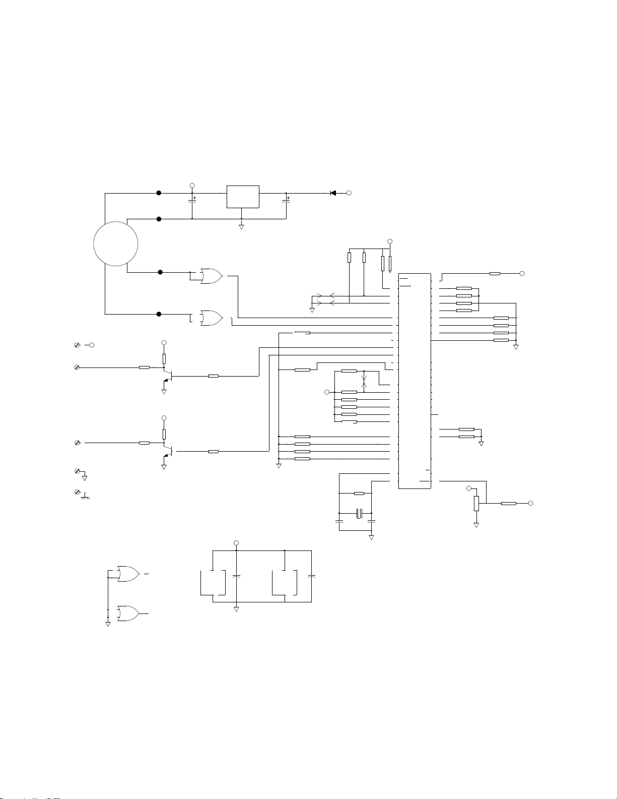
MD - 2000A SERIES SCHEMATIC
1TB
P15V
1
RED
CW
2
WHT
to associated
integrator
CCW
3
BLU
D COM
BLK
GND
GRN
4
5
ENCODER
P15V
UNUSED
74HCT32
1
2
74HCT32
9
10
IC2
IC2
R1
499
R4
499
3
8
1CN
P5V
RED
OV
BLUE
A
GREEN
B
BLACK
P5V
P5V
R2
10K
Q2
2N4401
R3
10K
Q1
2N4401
74HCT32 14
P5V
C1
1MFD
74HCT32
4
5
74HCT32
12
13
IC2
IC2
IC2
R6
10K
R7
10K
V+
COM
OUT
7
6
11
P5V
INOUT
COM
COM
68HC11A1 48
C5
.1MFD
D1
P5V
1N5060
J1
J2
C6
.1MFD
P15V
R9
10K
RP3
750-10K
R8
10M
CR1
8MHZ
C3
27PF
R10
10K
J3
C4
27PF
P5V
RP3
750-10K
IC4
68HC11A1
41
IRQ
40
XIRQ
PC0
25
MODA
PC1
24
MODB
PC2
PC3
8
PA0
PC4
7
PA1
PC5
6
PA2
PC6
5
PA3
PC7
4
PA4
3
PA5
2
PB0
PA6
1
PB1
PA7
PB2
42
PD0
PB3
43
PD1
PB4
44
PD2
PB5
45
PB6
PD3
46
PB7
PD4
47
PD5
VRL
17
VRH
PE0
18
PE1
19
PE2
20
PE3
29
EXTAL
R/W
30 39
XTAL
RST
AS
E
26
31
32
33
34
35
36
37
38
16
15
14
13
12
11
10
9
21
22
27
28
MC34064
RP1
750-10K
RP1
750-10K
P5V
IC3
R5
10K
RP2
750-10K
RP3
750-10K
P5V
P5V
IN
C2
1MFD
RP1
750-10K
RP1
750-10K
RP1
750-10K
IC4
V+
COM
23
NOTE: Terminal block 1TB provides customer connection to integrator.
Refer to associated integrator manual for interconnecton wiring.
PL-361 10
ref. 10D775 rev.0
Page 13

MD - 2000A LOGIC DIAGRAMS
CW & CCW operation
clockwise counterclockwise
IC2 pin 6
IC2 pin 11
IC4 pin 4
IC4 pin 3
1TB 2
Speed Out
CW
1TB 3
Speed Out
CCW
PL-361 11
Page 14

Page 15

Page 16

c
Siemens Milltronics Process Instruments Inc. 2002
Subject to change without prior notice
Siemens Milltronics Process Instruments Inc.
1954Technology Drive, P.O. Box 4225
Peterborough, ON.Canada K9J 7B1
Tel: (705) 745-2431 Fax: (705) 741-0466
www.milltronics.com
Rev. 1.0
*7ml19981ec01*
Printed in Canada
 Loading...