

Page 1
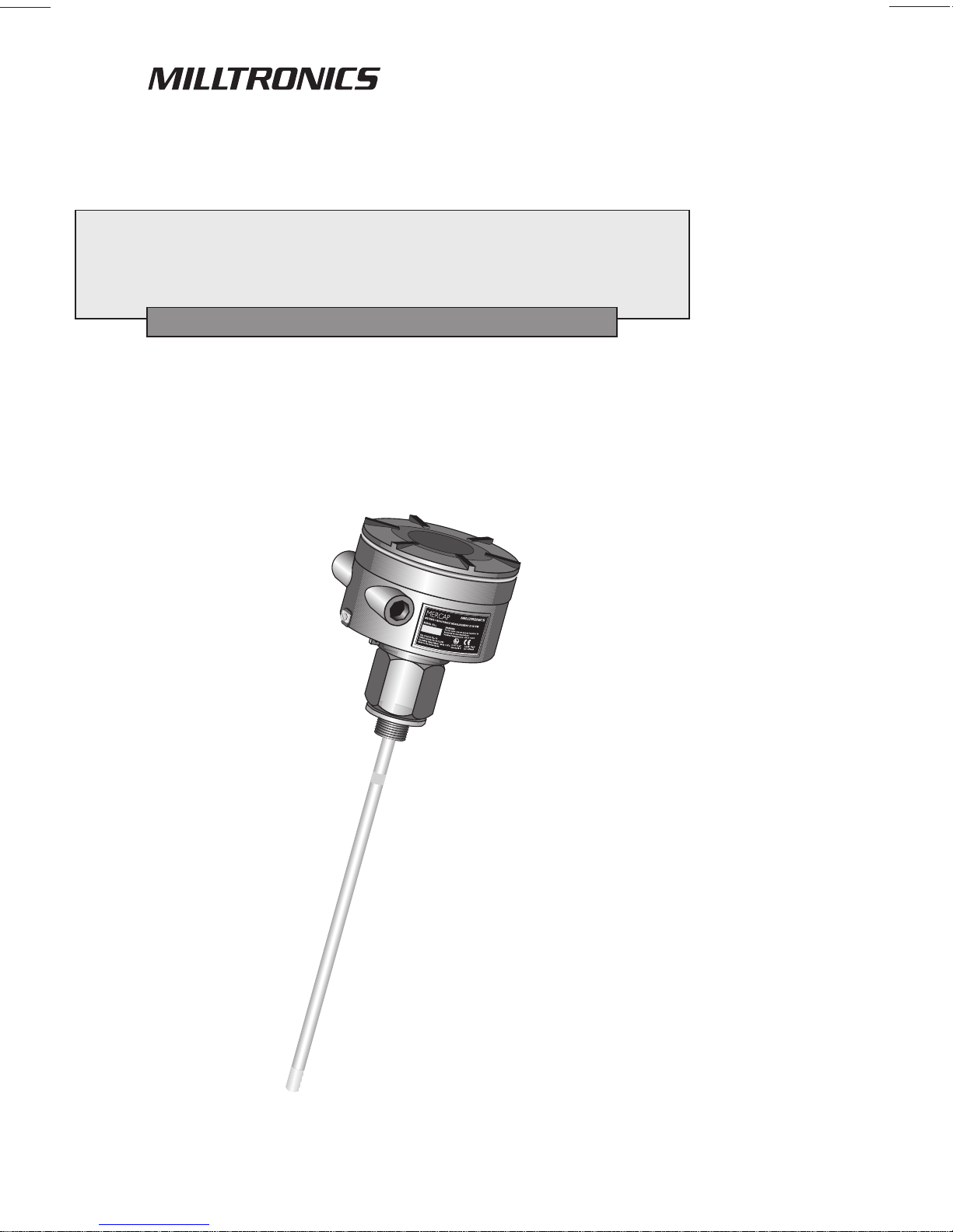
MERCAP
Instruction Manual
June 2001
Page 2

Safety Guideline s
Warning notices must be obser v ed to ensure personal safety as w ell as that of others, and to
protect the product and the connected equipment. These warning notices are accompanied
by a clarification of the level of caution to be observed .
Qualified Personnel
This device/system may only be set up and operated in conjunction with this manual.
Qualified personn el ar e only authorized to install and operate this equipment in accordance
with established safety practices and standards.
Warning: This product can only function properly and safely if it is correctly transported,
stored, installed, set up , operated, and maintained.
Note: Always use p r od uct in accordance with specifications.
Copyright Siemens Milltronics Process
Disclaimer of Liability
Instruments Inc. 2000. All Rights Reserved
This document is available in bound version and in
electronic version. We encourage users to
purchase authorized bound manuals, or to view
electronic versions as designed and authored by
Siemens Milltronics Process Instruments Inc.
Siemens Milltronics Process Instruments Inc. will
not be responsible for t he contents of partial or
whole reproductions of eit her bound or electronic
versions.
MILLTRONICS®is a registered trademark of Siemens Milltronics Process Instrume nt s Inc.
Contact SMPI Technical Publications at the following address:
Technical Publicat ions
Siemens Milltronics Process Instruments Inc.
1954 Technology Drive, P.O. Box 4225
Peterborough, Ontari o, Canada, K9J 7B1
Email: techpubs@millt ronics.com
While we have verified the contents of
this manual for agreement w it h t h e
instrumentation described, variations
remain possible. Thus we cannot
guarantee full agreement. The
contents of this manual are regularly
reviewed and corrections are included
in subsequent editions. We w elcome
all suggestions for improvement.
Technical data subject to change.
For the library of SMPI instr uction manuals, visit our Web site: www.milltronics.com
© Siemens Milltronics Process Instruments Inc. 2001
Page 3

Table of Contents
Introduction
Introduction ................................
IntroductionIntroduction
Technical Specifications
Technical Specifications ................................
Technical SpecificationsTechnical Specifications
Electrodes and Process Connections
Electrodes and Process Connections ................................
Electrodes and Process ConnectionsElectrodes and Process Connections
................................................................
................................................................
................................................................
................................................................
................................................................
................................................................
Identifications and Abbreviations ..............................................................................................3
................................................................
................................................................
................................................................
................................................................
Electrodes.........................................................................................................................................5
Wetted Parts....................................................................................................................................5
Transmitter.......................................................................................................................................5
................................................................
................................................................
Handling of Electrodes..................................................................................................................7
Characteristics ................................................................................................................................7
General Design Principles ...........................................................................................................8
Mercap Configurations.................................................................................................................9
Examples of Mercap Level Instruments ................................................................................10
Interface and Level Version (Mercap MCP 02)....................................................................15
Flanges ............................................................................................................................................17
Flange Standards .........................................................................................................................17
Applications Examples................................................................................................................19
....................................
................................................................
..............................................
................................................................
........................................................
................................................................
........................ 7777
................................................
.... 3333
........
.............. 5555
............................
Flow-Through Electrode
Flow-Through Electrode ................................
Flow-Through ElectrodeFlow-Through Electrode
................................................................
................................................................
FTS Series ......................................................................................................................................21
FTF Series.......................................................................................................................................22
MST9500 Transmitter
MST9500 Transmitter ................................
MST9500 TransmitterMST9500 Transmitter
................................................................
................................................................
................................................................
................................................................
Operating Principles ....................................................................................................................24
Installation
Installation and Interconnection
InstallationInstallation
and Interconnection................................
and Interconnectionand Interconnection
................................................................
................................................................
Interconnection.............................................................................................................................26
Connection Diagrams..................................................................................................................27
Factory settings ............................................................................................................................29
Applications
Applications and Grounding
ApplicationsApplications
Start-up
Start-up ................................
Start-upStart-up
Maintenance
Maintenance ................................
MaintenanceMaintenance
and Grounding ................................
and Groundingand Grounding
................................................................
................................................................
Push-Button Adjustment ............................................................................................................35
Adjustment using HART
................................................................
................................................................
................................................................
................................................................
................................................................
................................................................
TM
..........................................................................................................36
................................................................
................................................................
Test function ..................................................................................................................................39
................................................................
................................................................
................................................................
................................................................
................................................................
................................................................
................................................................
................................................................
................................................................
................................................................
..............................................
................................................................
..................................................
................................................................
................................ 25
................................................................
.......................................
................................................................
.........................................
................................................................
................................ 39
................................................................
.................. 24
....................................
.............. 21
............................
21
2121
24
2424
25
2525
....... 30
30
..............
3030
......... 35
35
..................
3535
39
3939
TM
TM
Appendix A: HART
Appendix A: HART
Appendix A: HARTAppendix A: HART
HART
HART
TMTM
Documentation
Documentation ................................
Documentation Documentation
TM
info.....................................................................................................................................41
TM
Conformance and Command Class .........................................................................41
MST9500 DD Menu/Variable Organization ..........................................................................43
TM
HART
Response Code information.......................................................................................44
General transmitter information...............................................................................................44
7ML19981CM01.1 MERCAP – INSTRUCTION MANUAL Page 1
................................................................
................................................................
........................................................
................................................................
........................ 41
................................................
41
4141
Page 4

Additional universal command specifications .....................................................................45
Additional common-practice command specifications .....................................................45
Transmitter specific commands...............................................................................................47
Appendix B: Tables
Appendix B: Tables
Appendix B: TablesAppendix B: Tables
Table A Conversion......................................................................................................................54
................................
................................................................
................................................................
................................................................
................................................................
.....................................................
................................................................
..................... 54
..........................................
54
5454
Table B Total Loop
Table C Voltage Drop Versus mA For Current Transmitter Operation....................................55
Appendix C: Approvals
Appendix C: Approvals................................
Appendix C: ApprovalsAppendix C: Approvals
CE Certificate .................................................................................................................................56
Certificates and Approvals ........................................................................................................57
Control Drawing FM/CSA Approval Mercap ........................................................................58
Index
Index ................................
IndexIndex
................................................................
................................................................
Ω Versus Supply Volts..........................................................................55
................................................................
................................................................
................................................................
................................................................
................................................................
................................................................
................................................................
................................................................
.................................................
................................................................
..............................................
................................................................
................. 56
..................................
.............. 59
............................
56
5656
59
5959
Page 2 MERCAP – INSTRUCTION MANUAL 7ML19981CM01.1
Page 5

Introduction
The Mercap system is a high performance, level measurement instrument consisting of a
sophisticated, easy-to-adjust, transmitter (MST9500) combined with measurement electrodes
and process seals designed to accommodate numerous configurations. The electrode,
comprised of a measurement section and an active shield section, is the primary sensor of
the system, and it indicates the electrical capacitance value of the measurement section
relative to the environment (tank wall, stilling well, or conductive material). This electrode
then connects to the capacitance detector portion of the two-wire loop powered electronic
transmitter. The measurement section can be set up to measure the level of solids, liquids
and slurries, as well as the interface between two immiscible liquids.
The manual is presented in three sections:
1. The electrode process connections and seals
2. The transmitter
3. Appendix sections providing supplementary information.
Identifications and Abbreviations
Various mnemonics and abbreviations are used in this manual. See below:
Short form Long Form Description Units
CE /FM /CSA Conformitè Europèene/
Factory Mutual/Canadian
Standards Association
DAC Digital Analog Converter
DCS Distributed Control System Control Room apparatus
Ex Explosion Proof
Exd Flame Proof
FV Full Vacuum
ESD Electrostatic Discharge
TM
HART
LRV Lower Range Value value for 0 % 4 mA
LSL Lower Sensor Limit below which PV is incorrect
pF pico Farads 0.000000000001 Farad
ppm parts per million
PV Primary Variable measured value
Stilling Well grounded metal tube with
SV Secondary Variable equivalent value
SVLRV Sec. Var. Lower Range Value 0 % equivalent value
SVURV Sec. Var. Upper Range Value 100 % equivalent value
µF
URV Upper Range Value value for 100% 20 mA
µSec
USL Upper Sensor Limit above which PV is incorrect
Highway Addressable
Remote Transducer
openings
micro Farads 0.000001 Farad
micro Seconds 0.000001 Seconds
HARTTM Communication Foundation, Austin, Texas, USA
7ML19981CM01.1 MERCAP – INSTRUCTION MANUAL Page 3
Page 6

Page 4 MERCAP – INSTRUCTION MANUAL 7ML19981CM01.1
Page 7

Technical Specifications
Electrodes
Process connections
Screw mounting:
Flange mounting:
Process material: C 22.8 N, AISI 316 L, Monel 400, Hastelloy C22
Probe diameter (mm/inch): 9/0.35 (cable), 16/0.63 (rod), or 24/0.95 (rod)
Probe length (mm/inch)
Rod version:
Cable version:
Probe lining: PFA, Enamel, PTFE
NPT, BSPT, JIS.
ANSI, DIN
5500/216
35000/1378
Pressure rating (bar/psi): FV - 200/2920 up to 525/7665 as option
Temperature rating (°C/°F): -200°/-328° to 200°/392° up to 450°/842° as option
Wetted Parts
Liner: PFA/PTFE
Flange: stainless steel or teflon lined
Transmitter
Measurement range (pF): 0 – 3300
Span (pF): minimum 3.3
Supply voltage (Vdc): • maximum 33
• minimum 12 Vdc at 3.6 mA
• minimum 9.5 Vdc at 22 mA
Output current (mA): 3.6 – 22 / 22 - 3.6 (2-wire current loop)
Smart communication: Acc. the HART Communication Foundation (HCF)
Temperature range (°C/°F): -40°/-40° to 85°/185° (ATEX–Explosion Proof: -20°/-4° to
7ML19981CM01.1 MERCAP – INSTRUCTION MANUAL Page 5
60º/140º)
Page 8

Temperature stability:
0.15 pF (0pF) or <0.25% (typically <0.1%) of actual
measurement value, whichever is greater over the full
temperature range of the product.
Non linearity and
< 0.1% full scale and actual measurement respectively
reproducibility:
Accuracy: <0.1% of actual measurement value
Features: • polarity protection input circuit
• E.S.D. protected (Loop)
• galvanically isolated measurement circuit
• fully potted with epoxy resin
Diagnostics (Includes fault
alarm):
• primary variable (PV) out of limits
• system failure measurement circuit
• deviation between A/D and D/A converter values
• check sum
• watch dog
• measurement current out of range
Measurement current
NAMUR NE 43
signalling:
Function rotary switch
Position 1:
Position 2:
Position 3:
1
4 mA measurement value (set)
20 mA measurement value (set)
3.8 up to 20.5 mA range by means of a field service
programmer
Position 4:
functionality test
Approvals: • Cenelec, FM/CSA (IS), FM (Ex-proof), CE, ATEX
1
HART communication in all switch positions
Page 6 MERCAP – INSTRUCTION MANUAL 7ML19981CM01.1
Page 9

Electrodes and Process Connections
This section of the manual is designed to assist in the determination of the best possible
probe configuration for your application. Therefore, we discuss the electrodes and process
connections before the instrumentation and the operation procedures. When configuring the
unit to your application, use the sample configurations below as your criteria.
Mercap electrodes come in a variety of formats to provide the necessary characteristics for
correct mounting, chemical compatibility, temperature and pressure requirements, and
dielectric constant. Most applications use the simple threaded connection, which is directly
mounted in the tank with the mating threaded nipple, or with a flange adapter that includes a
threaded hole.
For applications requiring higher temperature and pressure, or greater integrity, welded and
solid machined flange versions are available with single or double cone seals, and/or a
second seal on the flange plate to avoid any metallic wetted parts.
Handling of Electrodes
WARNING: Do not scratch or gouge the PFA electrode insulation since this could
reduce the integrity of the insulation and the useful life of the electrode.
WARNING: Be careful with an enamel insulated electrode. Normally an enamel lining
is protected by a stilling well, which is part of the design.
WARNING: Do not damage the insulation jacket on the electrode during shipping,
packing, and installation. Most electrodes use PFA insulation, a very dense and reliable
type of Teflon that prevents leakage and corrosion of the metal electrode and acts as
an insulator when conductive materials are being measured. Any damage to the
electrode can prevent proper performance.
WARNING (ATEX 100): Precautions MUST be taken to avoid ignition due to
hazardous electrostatic charges when an isolated probe is used in a potentially
explosive atmosphere caused by gas, vapor, or a non-conductive liquid, requiring
apparatus group IIC equipment. Or when the probe is used in a potentially explosive
atmosphere caused by dust.
7ML19981CM01.1 MERCAP – INSTRUCTION MANUAL Page 7
Page 10

Characteristics
The following characteristics apply to all general connection configurations:
• The standard Mercap insulated electrode is designed for use in both
conducting and non-conducting liquid applications.
• All electrodes consist of an active shield portion and a measurement portion,
which combine to form the complete electrode.
• The sum of the active shield length and the measurement length is the total
insertion length.
• The active shield design provides continuous immunity to the known changes
in conditions at the top of many vessels, where levels of vapours, dust, and
condensation are constantly changing.
• All changes in capacitance due to temperature and pressure changes that
could cause small changes in the seal geometry are also isolated from the
measurement signal because they are not included in the starting
capacitance of the electrode by virtue of the action of the active shield.
• Due to the well-controlled diameter of the electrodes and insulation, a linear
output is achieved over a wide range of capacitance values (3.3 to 3300 pF).
• The end seal is formed as an integral part of the electrode lining, giving
smooth and uniform insulation characteristics (tested to 55 kV).
• Standard single cone usage
• Secondary cone usage
General Design Principles
The Mercap capacitance level instrument combines an optimum combination of mechanical
and electrical/electronic principles in its design. Combining a single transmitter with as few
electrode configurations as possible maximizes the number of potential applications while it
minimizes the complexity of the instrument.
In principal, the standard threaded process connection (S-Series) with PFA insulated
electrode, including the active shield, provides good results in all measurement situations that
are within the temperature, pressure, and corrosive capabilities of the materials and seals.
This is true over a wide range of dielectric constants in both non-conducting and conducting
materials.
Applications outside of the standard capabilities of the S-Series would require a different
design configuration. These non-standard applications include:
Non-Standard Application Mercap Configuration
Non-metallic tanks with both conducting
and non-conducting liquids.
Non-conducting liquids in spherical and
horizontal-cylindrical tanks.
Highly corrosive materials requiring no
metallic wetted parts.
High pressure and temperature (greater
than 200 bar) with conductive liquid.
Sanitary/food safe applications. Use Mercap MCP 03.
Use a stilling well to provide second
electrode reference.
Use a stilling well as linearizer.
Use flange mount with D, DD seal
version.
Use HP version.
Page 8 MERCAP – INSTRUCTION MANUAL 7ML19981CM01.1
Page 11
Mercap Configurations
The Mercap is a versatile level measurement instrument that can be designed for your
specific application by taking the following conditions into consideration:
Process Connections
Any standard process connection is available with Mercap, and special versions can be
fabricated to match the mounting and application requirements. Various sizes of threaded
and flanged fittings are available.
Seal Types
The basic internal seal for the Mercap is of a conical-shaped, preloaded pressure/leak
resistant construction. Up to three levels of seal protection are implemented depending on
the integrity requirements of the application. A single or double cone internal seal forms 1 or 2
blocks against leaking, and a third flange face gasket is also available in the D and DD seal
construction. The flange face seal also provides a design with no metal wetted parts if
required.
Pressure and Temperature Considerations
The maximum temperature and pressure of operation for the standard Mercap level probe is
200°C (392°F) and 200 bar (2900 psi). There are, of course, qualifications that must be applied
to these maximums.
Enamel probes are suggested when process temperature exceeds 200 °C, and/or in
combination with very high pressure.
Note:
: Consult Milltronics for chemical applications other than water.
: :
Process Connection and Seal Configuration of Mercap
Process Connection
Process Connection Seal Type
Process ConnectionProcess Connection
Threaded S Single Cone
Welded Flange S Single Cone
Solid Machined
Flange
Seal Type Seal Description
Seal TypeSeal Type
S Single Cone
D Single Cone + Teflon flange seal
DD Double Cone + Teflon flange seal Consult factory*
SD Double Cone (used for stilling well applications)
HP Consult factory*
Seal Description
Seal DescriptionSeal Description
Note: HP (high pressure) is only supplied with enamel insulation and a recommended
stilling well for protection of the enamel. A cone seal plus a secondary redundant seal
is provided between the electrode and the stilling well.
7ML19981CM01.1 MERCAP – INSTRUCTION MANUAL Page 9
Page 12
Examples of Mercap Level Instruments
The following graphics illustrate the variation in configurations available for the Standard
series, Level and Interface series, and Sanitary series Mercap level instrument.
Note: All measurements are given in millimeters/inches.
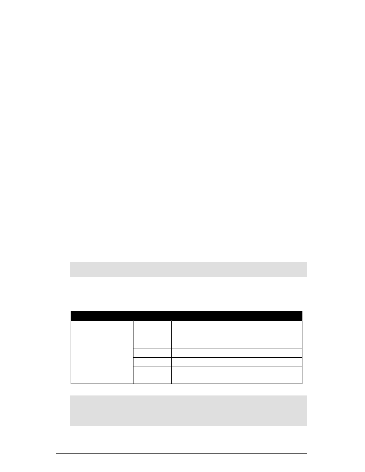
Standard Level Version (Mercap MCP01)
This is the most common version of Mercap and is available with the following features:
• Threaded flanges, welded flanges, and solid flanges
• S series, D series, SD series, DD series, and HP series process seals.
• Selections of standard ANSI and DIN flanges are available
• The most common electrode is insulated with PFA, but Enamel (HP seal) is also
available as standard (Enamel is only available on rigid design).
• Various process connection materials are also available
• Rigid and Flexible Cable versions available
MCP01 (Standard) S-Series: Threaded Versions
S-Series: Threaded
∅160
(6.3”)
Active Shield
Insertion
Insertion
Length+175
(6.9”)
Length
Inactive Tip
Page 10 MERCAP – INSTRUCTION MANUAL 7ML19981CM01.1
Active
Length
40 (1.57")
∅16 (0.63”)
or ∅24 (0.94")
Page 13
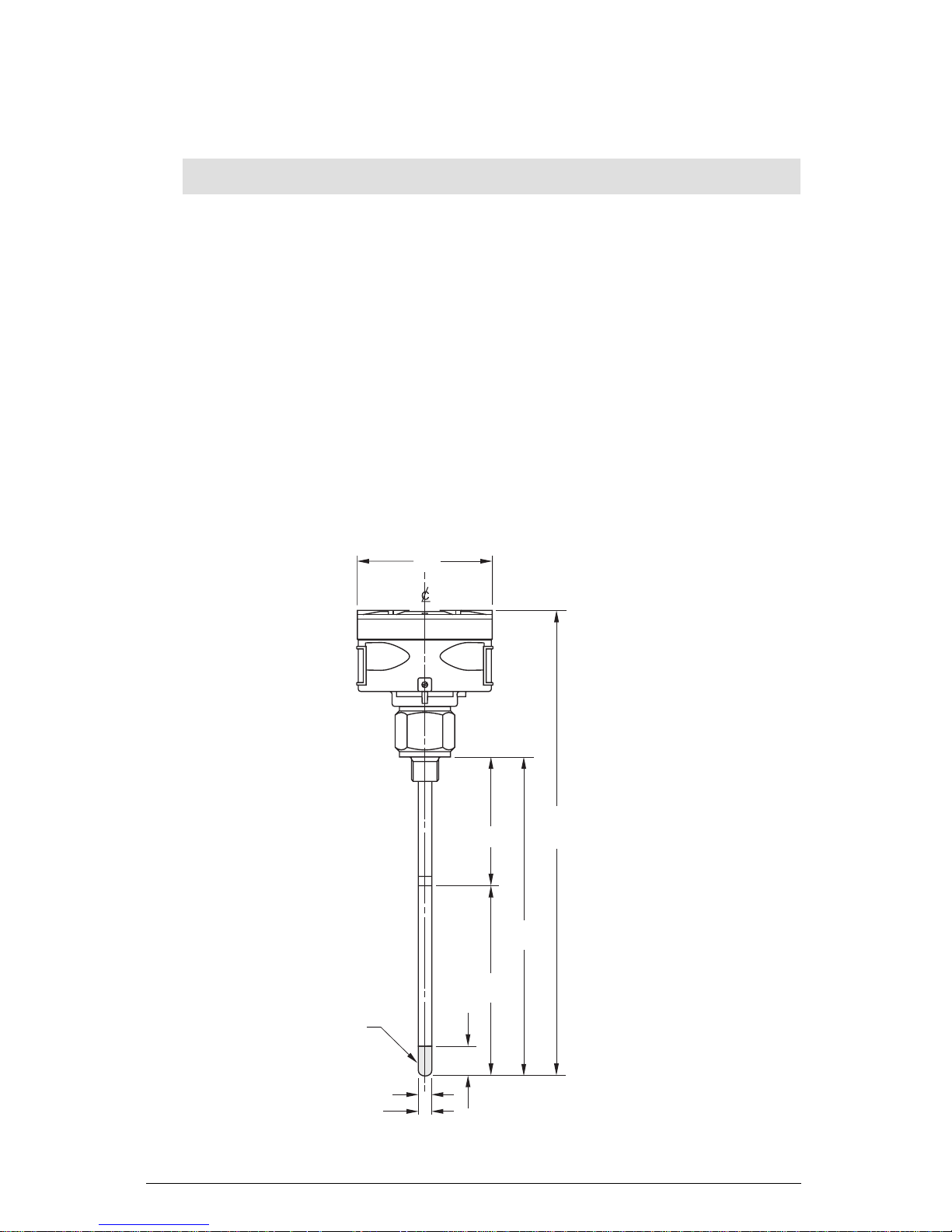
120 (4.72")
S-Series Cable Version S-Series Cable Version
(with anchor)
∅160 (6.3”)
Transmitter
Enclosure
55 (2.17")
Insertion Length
Dimension
Varies
Seal Gland
Threaded Process
Connector
See Order
Instructions
PTFE Insulation
∅9 (0.35")
Tensile Weight+/-Varies
Inactive
Part
125 (4.9")
Insertion
Length
+175 (6.9")
Insertion
Length
MCP01 S-Series Threaded Features
• single process seal
• suitable for most level, interface, or detection applications
• high temperature and pressure resistance
7ML19981CM01.1 MERCAP – INSTRUCTION MANUAL Page 11
Page 14
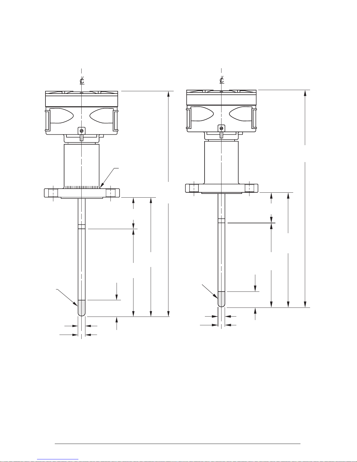
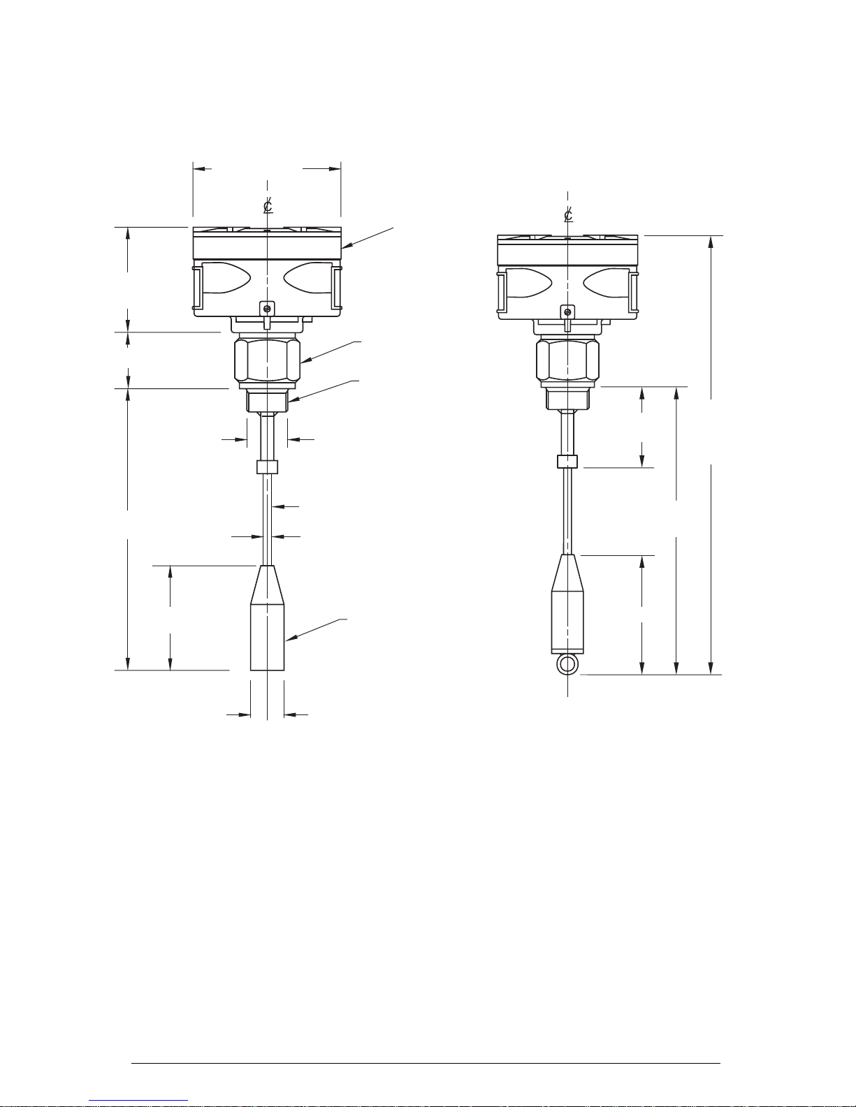
MCP01 (Standard) S-Series: Welded and Machined Flanged
Versions
S-Series Welded Flange S-Series Machined Flange
TIG Weld
Insertion
Length
+185 (7.28")
Insertion
Length
+185 (7.28")
Inactive Tip
∅16 (0.63”)
or ∅24 (0.94")
Active Shield
Insertion
Length
Active
Length
Inactive Tip
40 (1.57")
∅16 (0.63”)
or ∅24 (0.94")
MCP01 S-Series Flange Features
• single process seal
• suitable for most level, interface, or detection applications
• high temperature and pressure resistant
Active Shield
Insertion
Length
Active
Length
40 (1.57")
Page 12 MERCAP – INSTRUCTION MANUAL 7ML19981CM01.1
Page 15
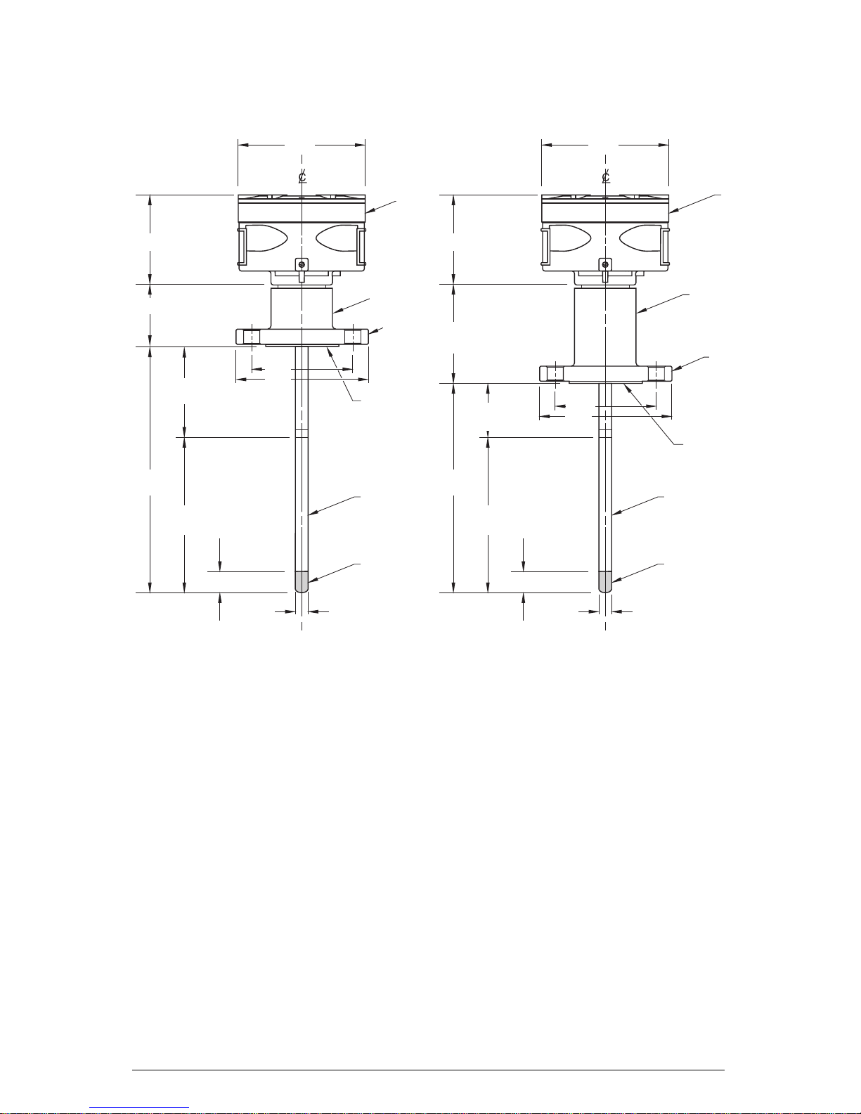
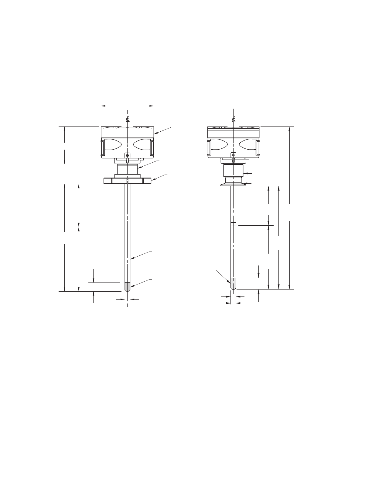
MCP01 Standard D-Series: Machined Flanged Versions
k
k
D-Series DD-Series
∅160 (6.3") ∅160 (6.3")
65 (2.56")
Insertion
Length
Transmitter
Enclosure
120 (4.72") 120 (4.72")
n
holes
Active
Shield
Active
Length
40 (1.57") 40 (1.57")
∅
∅D
Flange
Process
Connection
PTFE Lining
Probe
Inactive Tip Inactive Tip
120 (4.72")
Insertion
Length
Active
Shield
Active
Length
n
holes
Transmitter
Enclosure
Seal GlandSeal Gland
Flange
Process
Connection
∅
∅D
PTFE Lining
Probe
∅16 (0.63”) or
∅24 (0.94")
MCP01 Standard D-Series Features
• single process seal
• all wetted parts made of PFA (probe
lining) or PTFE (flange face)
• according to NACE requirements
∅16 (0.63”) or
∅24 (0.94")
MCP01 Standard DD-Series Features
• double process seal
• redundant safety (e.g. Phenol,
Phosgene applications, etc.)
• all wetted parts made of PFA (probe
lining) or PTFE (flange face)
• according to NACE requirements
• suitable for turbulent and toxic
chemical applications
7ML19981CM01.1 MERCAP – INSTRUCTION MANUAL Page 13
Page 16
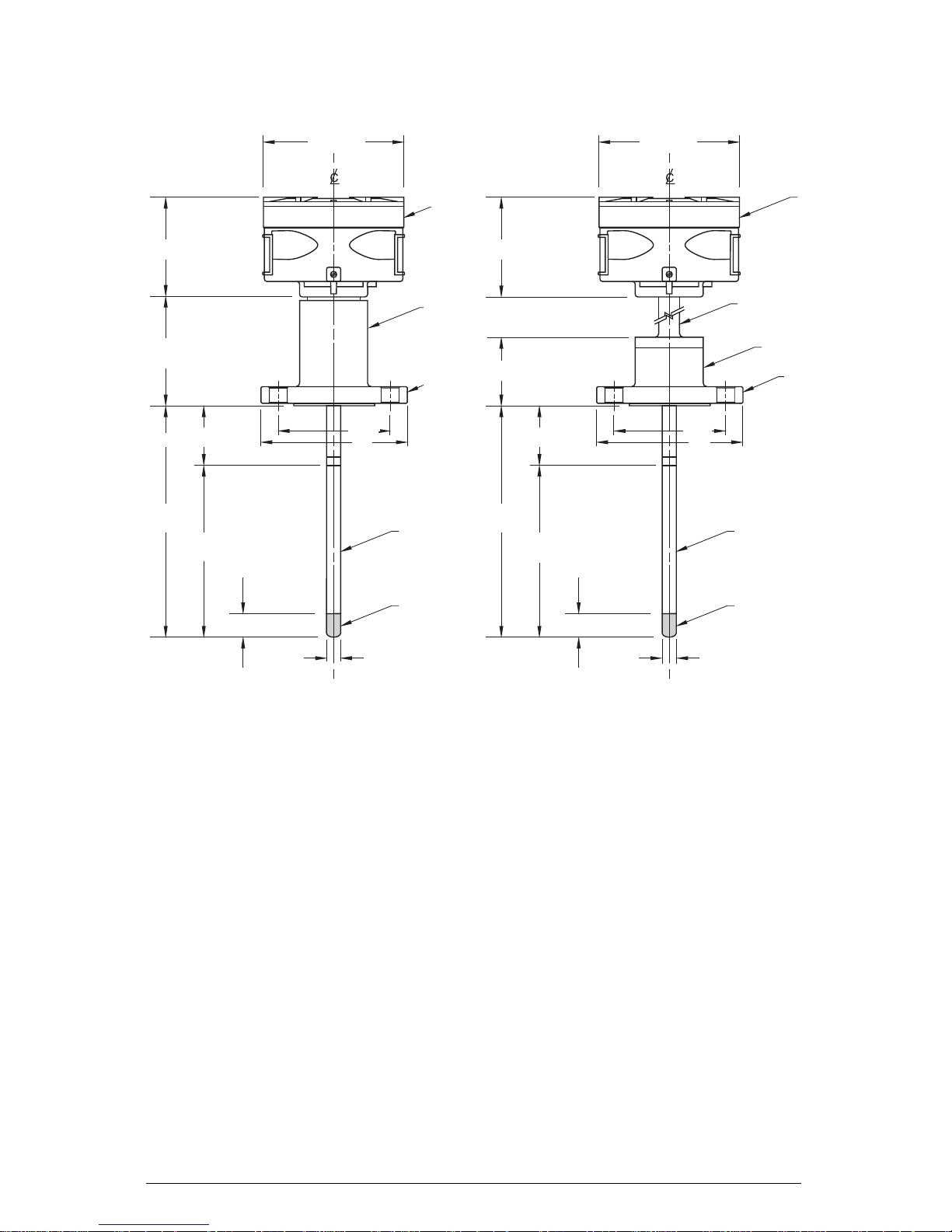
SD-Series Probe/Thermal Isolator
k
k
∅160 (6.3") ∅160 (6.3")
Transmitter
Enclosure
120 (4.72") 120 (4.72")
Seal
Dependent on
Gland
extension length
120 (4.72")
Active Shield Active Shield
Insertion
Length
Active
Length
n
holes
∅
40 (1.57") 40 (1.57")
∅16 (0.63”) or
∅24 (0.94")
Flange
Process
Connection
Probe
Inactive Tip Inactive Tip
85 (3.35")
Insertion
Length
Active
Length
n
holes
Transmitter
Enclosure
Thermal
Isolator
Seal
Gland
Flange
Process
Connection
∅
∅D ∅D
Probe
∅16 (0.63”) or
∅24 (0.94")
MCP01 Standard SD-Series Features
• double process seal
• redundant safety (e.g. Phenol,
Phosgene applications, etc.)
• all wetted parts made of PFA/PTFE
• according to NACE requirements
• suitable for turbulent and toxic
chemical applications
MCP01 Probe/Thermal Isolator
Features
• thermal isolator
Page 14 MERCAP – INSTRUCTION MANUAL 7ML19981CM01.1
Page 17
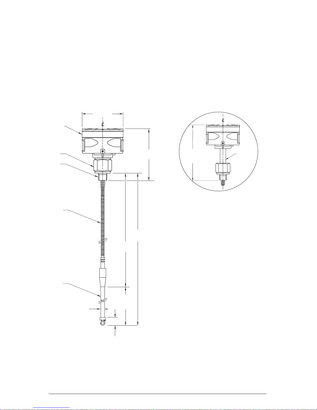
Interface and Level Version (Mercap MCP 02)
This version is designed specifically for interface level where a long distance active shield
portion of the electrode is required (up to 35 meters) before the measurement portion of the
electrode begins. This type of application is common in large storage tanks for oil where the
bottom of the tank invariably has a layer of water below the oil. Often, when measurement
spans as much as 5.5 meters (for the water), up to 35 meters of flexible bellows cable are
used.
MCP02: Interface Version
∅160 (6.3")
Transmitter
Enclosure
Seal
Gland
Process
Connection:
flange or
threaded
mounting
185 (7.28")
Dependent on
extension length
Adjustable
extension
part
Flexible
Tube
Probe
∅16 (0.63”) or
∅24 (0.94")
Active Shield
Active Length
∅16 mm=2m
∅24mm=5.5m
100 (3.9")
Inactive Tip
Insertion Length
35m (115ft) max.
Process Connection Size
• threaded version: ¾", 1", 1½", 2"
NPT, BSPT, or JIS
• sanitary version: on customer
request
• flange version: on customer
request
Options
• thermal isolator
• stilling well
Aluminum Enclosure
• Nema 4/Type 4/IP65
Conduit Entry:
• ½" NPT (2x)
7ML19981CM01.1 MERCAP – INSTRUCTION MANUAL Page 15
Page 18
Sanitary Level Version (Mercap MCP 03)
The hygienic design includes threaded and tri-clamp versions for use in the food and
pharmaceutical industry.
MCP03: Sanitary Versions
Sanitary Thread Coupling Sanitary Tri-Clamp
∅160 (6.3")
Transmitter
Enclosure
118 (4.65")
Seal Gland
Active
Shield
Insertion
Length
Active
Length
40 (1.57")
Probe
Inactive Tip
∅16 (0.63”) or
∅24 (0.94")
MCP03 Sanitary Tri-Clamp Features
• maximum active length 5.5m
• minimum active length 50mm
IDF Nut
Inactive Tip
∅16 (0.63”) or
∅24 (0.94")
Seal Gland
Tri-clamp
Connection
Active
Length
40 (1.57")
Active
Shield
Insertion
Length +
175 (6.9")
Insertion
Length
Page 16 MERCAP – INSTRUCTION MANUAL 7ML19981CM01.1
Page 19
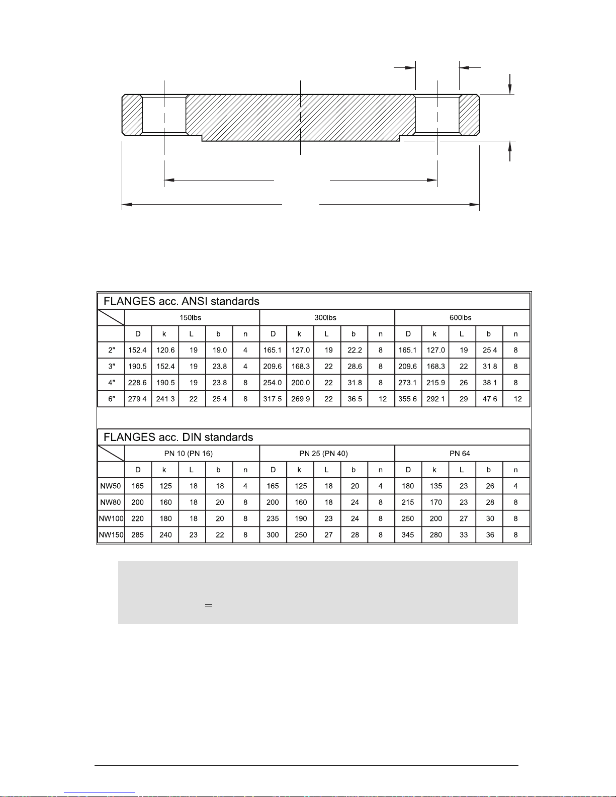
Flanges
Flange Standards
øL
b
øK (n holes)
øD
Note:
• All Sizes: MM
• One (1) inch: ^ 25.4mm
• Details: See drawings, technical data, and measuring probe details
7ML19981CM01.1 MERCAP – INSTRUCTION MANUAL Page 17
Page 20

Temperature Versus Pressure Curve Mercap Level Probe
In this situation, as the temperature reaches 75°C (167°F) the maximum pressure must be
derated. As the temperature reaches 200°C (392°F) the maximum pressure is limited to 50 bar
(725 psi). This curve is typical for water only, for other, more aggressive chemicals the
derating curve will be more severe.
Reference Product: Water
Note: For high temperature and pressure ratings for the Enamel probe, please
contact your Siemens Milltronics representative.
Page 18 MERCAP – INSTRUCTION MANUAL 7ML19981CM01.1
Page 21

Applications Examples
Generic Application Calculations
The capacitance expected in a cylindrical tank with a probe centrally mounted is estimated
using the following formula:
_air 24x0.95 pF = 12.7pF
C=ξ
r
a
Log (1/0.016)
In which
C = capacitance value in pF
ξ
= relative dielectric constant
r
L = active measurement length in
meters
D = internal tank diameter in meters
d = electrode diameter in meters
ξ
= 1 (air)
r
= 2 (oil)
ξ
r
24 = a K constant (can be substituted for 7.32)
Mercap
d = 16mm
D
2
=1.0m
0.25m
L =0.95m
For Vessels Filled with Oil
The following equation applies to oil-filled vessels matching the dimensions shown above.
Please note that the probe must be properly mounted and the metal tank is grounded.
C
increase for oil=ξr
Log (1/0.016)
C
increase for oil=ξr
Log (1/0.016)
This means that the capacitance value for 0% to 100% changes from 12.7 to 25.4 pF. After
calibration then:
12.7 pF ≅ 0% ≅ 4 mA or 20 mA
25.4 pF ≅ 100% ≅ 20 mA or 4 mA
_oil-ξr _air 24x0.95 pF= 12.7pF
OR
_oil-ξr _air 7.32x3.12 pF= 12.7pF
7ML19981CM01.1 MERCAP – INSTRUCTION MANUAL Page 19
Page 22

A similar example in inches yields the following:
C
increase for oil=ξr
_oil-ξr _air 7.32x4.5 = 16.6 pF
Log (60/0.63)
So for this slightly larger tank, the
capacitance ranges from 16.6 pF to 33.2 pF.
So on calibration:
16.6 pF ≅ 0% ≅ 4 mA or 20 mA
33.2 pF ≅ 100% 20 mA or 4 mA
Mercap
6" (0.5ft)
L = 54"
(4.5ft)
d = 0.63"
60"
(5.0ft)
Page 20 MERCAP – INSTRUCTION MANUAL 7ML19981CM01.1
Page 23

Flow-Through Electrode
The Mercap flow-through electrodes provide the following multi-functional applications for a
liquid pipe system:
• quality measurement
• interface measurement and detection
• product presence detection
The measurement occurs without placing an obstacle in the product line and uses
capacitance to determine the physical characteristics of the product. In mixed liquids, the
flow-through electrode can measure the degree of proportions (e.g. water in oil). The
capacitance change is measured and transmitted by a 4-20/20-4mA signal and HART
protocol.
Note: If the transmitter's ambient temperature exceeds 85° C/185° F (70° C/158° F) in
Ex zones) mount a thermopart between electrode head and transmitter housing.
FTS Series
The FTS series flow-through electrode is suitable for relatively high pressure and
temperature conditions. It is installed using a sandwich connection between two flanges and
a PTFE sealing ring to provide high chemical resistance.
Note: For flange dimensions and pressure ratings, refer to the chart on page 23.
ø160mm
(6.3")
125mm (4.9")
200mm (7.9")
200mm (7.9")
+ Y
Transmitter
Enclosure
2 X ½" NPT
Cable Entry
Electrode
Housing
Sandwich
Connection
øX
øY
7ML19981CM01.1 MERCAP – INSTRUCTION MANUAL Page 21
PTFE lining
55mm
(2.1")
Page 24

FTS Specifications
Process Connections: Sandwich, acc. ANSI and DIN standards (table p. 23)
Fitting length: 55mm (2.1")
Material: AISI 316L or carbon steel C 35
Max. Pressure: 50 bar (dependent on pressure rated flanges)
Max. Temperature: 200°C (398°F)
Lining: PTFE (1mm thick)
Transmitter Enclosure Aluminum ø160mm (6.3")
Waterproof Classification: IP 65, NEMA 4/Type 4 acc. DIN 40050
FTF Series
The FTF series flow-through electrode is designed to accommodate the combination of hightemperature and high-pressure conditions. The electrode is installed using a flange mounting,
and the PTFE sealing ring provides high chemical resistance.
Note: For flange dimensions and pressure ratings, refer to the chart on page 25.
ø160mm
(6.3")
Transmitter
Housing
øX
øD
Bolt hole
180mm (7")
180mm (7") + D
2 X ½" NPT
Cable Entry
125mm (4.9")
Electrode
Housing
(The length of the housing
changes to accommodate
flange diameter.)
Flange
Connection
PTFE Lining
100mm
(3.9")
Page 22 MERCAP – INSTRUCTION MANUAL 7ML19981CM01.1
Page 25

FTF Specifications
Process Connections: Flange, acc. ANSI and DIN standards (table p. 23)
Fitting length: 100mm (3.9")
Material: AISI 316L or carbon steel C 35
Max. Pressure: 50 bar (dependent on pressure rated flanges)
Max. Temperature: 200°C (398°F)
Lining: PTFE (1mm thick)
Transmitter Enclosure: Aluminum ø160mm (6.3")
Waterproof Classification: IP 65, NEMA 4/Type 4 acc. DIN 40050
Flanges acc. ANSI Standards (inches)
class ► 150 lbs 300 lbs 600 lbs
nom. size ▼ Dx y D xy D x y
1" 4.3 1.1 2.5 4.9 1.1 2.8 4.9 1.0 2.7
2" 6.0 2.1 4.0 6.5 2.1 4.3 6.5 1.9 4.2
3" 7.5 3.1 5.2 8.2 3.1 5.7 8.3 2.9 5.7
4" 9.0 4.0 6.7 10.0 4.0 7.0 10.8 3.8 7.5
5" 10.0 5.1 7.6 12.5 5.1 8.4 13.0 4.8 9.4
8" 13.5 8.0 10.9 15.0 8.0 12.0 16.5 7.6 12.5
10" 16.0 10.0 13.3 17.5 10.0 14.1 20.0 9.8 15.6
12" 19.0 12.0 16.0 20.5 12.0 16.5 22.0 11.8 17.9
Flanges acc. DIN Standards (mm)
class ► PN 16 PN25 PN40
nom. size ▼ Dx y D x y D x y
NW 25 115 24.8 71 115 24.8 71 115 24.8 71
NW 50 165 51.2 107 165 51.2 107 165 51.2 107
NW 80 200 82.5 142 200 82.5 142 200 82.5 142
NW 100 220 100.8 162 235 100.8 167 235 100.8 167
NW 125 250 125 192 270 125 193 270 125 193
NW 150 285 150 217 300 150 223 300 150 223
NW 200 340 204.2 272 360 203.4 283 375 203.4 290
NW 250 405 254.4 328 425 252.8 340 450 252.8 352
NW 300 460 303.8 383 485 302 400 515 302 417
7ML19981CM01.1 MERCAP – INSTRUCTION MANUAL Page 23
Page 26

MST9500 Transmitter
t
Operating Principles
The instrument's MST9500 transmitter measures the capacitance of a sensor/electrode
relative to the reference electrode (often the tank wall) and transforms it to a 4-20 mA signal.
Applications include level measurement, level detection, flow measurement, and flow
detection.
The measurement capacitance is usually obtained by using an insulated probe inserted in the
tank, forming one electrode of the capacitor. The wall of the tank forms the other electrode of
the capacitor.
A stilling well is used when the silo or tank is not conductive, or when the shape of the tank
cannot guarantee linear measurement. The stilling well is a (grounded) metal tube with vent
openings, which fits around the electrode. The stilling well diameter is somewhat larger than
the diameter of the electrode, depending on the application.
A significant advantage of the MST9500 is the Active Shielding feature. It prevents any
capacitance that may occur in the connection cable, process connection, and non-active
parts of the probe from interfering with the measurement. As a result, the capacitance
registered by the MST9500 consists only of the measuring capacitor, and a more stable and
more reliable measurement is provided.
Conventional
Capacitance
Measurement
Measuring-Circuit
MST9500 with
Active Shield
Measuring- Circuit
C1 = Cap. connection poin
C2 = Cap. connection cable
C3 = Cap. Process connection,
includes inactive part
Ca = Initial capacitance (air)
Cm = Cap. Increasement (product)
Due to intrinsic safety requirements, the entire MST9500 transmitter is potted in epoxy resin
that also protects the electronics against mechanical vibration and moisture influences. The
-12
maximum measuring range of the MST9500 is 3300 pF (1pF ≅ 10
F).
The electrode is connected by means of a mini-coax cable. The screw connection is intended
for grounding the tank or stilling well.
Note: This ground must be connected to the tank and/or stilling well.
Page 24 MERCAP – INSTRUCTION MANUAL 7ML19981CM01.1
Page 27

Installation and Interconnection
This section discusses the following:
• housing types supplied with the MST9500
• supply voltage requirements
Transmitter Module Housing
The MST9500 electronics is housed in a plastic box and fully potted in epoxy resin. This
construction is necessary for EEx approval and protects the components against mechanical
shock and the influence of moisture. The microprocessor is placed on an IC socket so the unit
can be upgraded at a later stage by implementing software changes.
The processor chip is covered with a special sticker that contains product information and
acts as a protection seal for moisture.
Note: Damage or removal of the sticker voids the warranty for the MST9500.
In most cases, the transmitter is in a Milltronics-supplied metal housing, providing reliable
operation in environments with dust, moisture, and high frequency interference.
• cable requirements
• connection diagrams
The electronics operate at temperatures ranging between -40°C to 85°C, which means that
protection equipment, such as sun shields, are not normally required.
Metal Housing and Electrode Assembly
The MST9500 is mounted in a powder-coated aluminium housing. The housing provides a
separate customer wiring area in line with the cable conduit inlet/outlet openings.
Terminals for:
• Instrument connection (2-wire current loop)
• Ground connection (wire with a sufficiently large conductor diameter)
As the measurement occurs between the Measurement and Ground connection, it is
important to have good, low-resistance, reliable connections in this circuit.
IMPORTANT: A reliable and stable ground connection is required to achieve a stable and
reliable measurement.
For the Ground connection, a solid electrical connection must be made between the ground
point on the housing and the process connection with either a stilling well and/or tank wall.
In the Milltronics housing, the ground connection between the transmitter and the housing
has already been made with the ground connection point. The instrument system ground
must be connected to this ground connection point.
The instrument loop connection for the MST9500 is a 2-wire cable. The positive wire must be
connected to terminal
terminal
7ML19981CM01.1 MERCAP – INSTRUCTION MANUAL Page 25
2. (See the connection diagrams on page 27.)
1 (the terminal slot nearest the housing wall), and the negative wire to
Page 28

Incorrect power connection will not damage the MST9500. However, it can lead to a larger
current (~40 mA) through the loop, and it will not operate with incorrect polarity.
The MST9500 is isolated from the power supply that provides for the opportunity of grounding
either line (positive or negative) if requirements for Ex safety are followed and the power
supply voltage is less than 33 Vdc.
Caution: During connection, do not leave moisture or metal scrap (of the cable shielding
etc.) in the housing. This can interfere with transmitter operation.
Interconnection
Supply
The supply voltage requirements for the MST9500 are shown in the installation figures on
page 27. Because the MST9500 uses a switched power supply circuit, the required terminal
voltage
voltage depends on the total measuring current. In case of a higher current value, a lower
voltage voltage
terminal voltage is allowed.
For example, when using a 250 Ohm measuring resistance without barrier and cable resistance, the supply voltage should be at least 14.5V. A 250 Ohms measuring resistance, a barrier
of 280 Ohm, and 20 Ohm cable resistance (500 m) results in a total of 550 Ohm, therefore a
minimum supply voltage of 20.5 Volts (approx.). In case of a multi-drop application, where the
measuring current is fixed to 4 mA, the supply voltage on the terminals of the MST9500 should
be at least 12 Volts.
terminal
terminalterminal
Cable
The selection of the cable is mainly determined by two criteria:
1. The resistance of the copper conductor (Ohm)
2. The cable capacity (pF)
The copper resistance influences the voltage drop over the cable. The cable capacitance
influences the HART
example, it has a diameter of 1 mm
capacitance of 100 pF/m. To maintain reliable transfer of the HART
indicated that the RC time of the connection parts should never be more than 65 µSec. For
output signals (from the MST9500), only the cable and barrier resistance counts. For input
signals it is less favourable since the measuring resistance also counts.
(RB + RM) x CC should be max. 65 µSec. (R in Ohm, C in Farad, T in Sec). For a standard 28 V
280 Ohm barrier and a 250 Ohm measuring resistance, a field capacitance of 0.123 µF is
allowed. This is higher for IIC (I/S) applications than allowed; therefore, attenuation of HART
signal will not occur.
In IIB applications, where the maximum allowed capacity value is 0.33 µF, the cable length
allowed will be longer than actually allowed for HART™. Depending on cable specifications,
the maximum length lies between 1 and 3 km.
TM
signals and is important for intrinsically safe applications. If, for
2
, the result is a copper resistance of 36.8 Ohm/km and a
TM
modem signals, it is
When making Ex calculations, only the cable capacitance at the transmitter side of the barrier
counts. For damping calculations, the cable capacity at the other side of the barrier should
also be considered.
Page 26 MERCAP – INSTRUCTION MANUAL 7ML19981CM01.1
Page 29

Connection Diagrams
XP∗ (Cenelec) Version
Push Button
Command Selection Switch
Connector
Measuring Signal
Ground
4-20 mA loop connection
1 = positive wire (+)
2 = negative wire (-)
Ground
GP* (FM/CSA/Cenelec) Version / IS* (FM/CSA/Cenelec) Version /
XP* (FM) Version
Push Button
Command Selection Switch
Connector
Measuring Signal
Ground
4-20 mA loop connection
1 = positive wire (+)
2 = negative wire (-)
Current check – terminal 1 and 3
Ground
∗ GP = General Purpose
IS = Intrinsically Safe
XP = Explosion Proof
7ML19981CM01.1 MERCAP – INSTRUCTION MANUAL Page 27
Page 30

The MST9500 is equipped with three terminals, two of which are intended for connecting loop
A
power instrument cables. This connection is protected against incorrect polarity. The third
terminal allows the measurement of the current in the instrument cable with any digital
current meter instrument, without breaking the loop circuit.
The MST9500 also includes the following:
• command push-button
• command selection switch (4 positions)
position
position
position
position
1 record measured value for 4 mA
2 record measured value for 20 mA
3 field service use
4 TEST function
• 15 pin sub-D connector field service use
The transmitter is powered by the current loop and needs at least 9-13 Volt (9 V at 22 mA, 13 V
at 3.6 mA) on the terminals. The maximum supply is 33 Volt. In case of higher voltages, the
safety diode will conduct, leading to an increase in power consumption. Some overload can
be tolerated indefinitely.
As a result of well-designed circuitry, the internal capacitance and inductance on the
terminals are isolated and do not interfere with safety calculations.
The MST9500 is equipped with the HART
TM
communication protocol so that settings and
information can be obtained and altered locally or remotely.
The internal diagnostic functions continuously monitor the correct operation of the
electronics. An error signal is generated if a failure or irregularity occurs.
MST9500 sends the signal current according to the NAMUR NE 43 recommendation. This
means that the current remains between 3.8 and 20.5 mA during normal operation. If the
process exceeds its normal limits, the current will be limited to 3.8 or 20.5 mA.
If there is a transmitter fault in the MST9500, or a test (position
4) produces an error result,
the signal is changed to 3.6 or 22 mA.
Current values to signalize from digital transmitters
Measurement value (M)
Fault- m
Value (F)
Fault- mA
Value (F)
Current values for signal detection
Measurement value (M)
F:=0
Fault- mA
Value (F)
Fault- mA
Value (F)
mA
F:=1
Page 28 MERCAP – INSTRUCTION MANUAL 7ML19981CM01.1
F:=1
mA
Page 31

Whenever the local situation allows, the zero adjustment and the full scale can be recorded
with the press of a button. Furthermore, the HART
the MST9500 according to specific requirements.
The galvanic isolation between the measuring circuit and current loop provides immunity
during the use of cathode protected measuring tanks. Connection to PLC equipment is
possible without any problems.
TM
implementation allows for adjustment of
Factory Settings
The MST9500 has a number of default factory settings. If the required settings for the
application are known, the settings can be modified during final testing.
Settings:
Setting
Setting Description
SettingSetting
ID has a unique serial number
PV Units pF
USL(PV) 3300 pF
LSL(PV) 1.666 pF
URV(PV) 3300 pF [switch. position 2]
LRV(PV) 0.00 pF [switch. position 1]
AO1(PV) 4-20 mA is 0-100%
TAG "customer input data via HART"
DESCRIPTOR "customer input data via HART"
MESSAGE "Milltronics"
DATE "customer input data via HART"
SENSOR SERIAL NUMBER "customer input data via HART"
FINAL ASSEMBLY NUMBER "customer input data via HART"
SV Units UNDEFINED
SVLRV 0
SVURV 1.0
Description
DescriptionDescription
As the USL and LSL are set to 3300 respectively 1.666 pF, the following applies:
• The MST9500 can be adjusted with the push-button. The URV and LRV, which
should be inside
• Interruption of the measuring connection is detected. A loose or interrupted
connection results in to up to 0.5 pF capacity, which is below the adjusted LSL.
7ML19981CM01.1 MERCAP – INSTRUCTION MANUAL Page 29
inside the USL and LSL, can be set anywhere in the entire range.
inside inside
Page 32

Applications and Grounding
Several common applications appear in this section. Common applications are separated into
two types: those with System Grounding and those with Safety Grounding.
System Grounding (referencing)
The correct operation of the measuring system depends on the correct method of grounding.
Make sure that there is a reliable connection to the reference electrode (usually a metal
tank). Some common applications involving system grounding include:
• metal tanks
• metal tanks, cathodically protected
• non-conductive tanks
Metal Tanks
Metal tanks can be (and in
most cases are) normally
grounded.
The connection of the
MST9500 can be
accomplished as shown
here. If a stilling well is
used, it is important that its
metal parts are properly
grounded.
Ground Lug
Metal
Page 30 MERCAP – INSTRUCTION MANUAL 7ML19981CM01.1
Page 33

Cathodically
Protected Metal
Tanks
Cathodically protected metal
tanks are never directly
grounded. However, the
impedance of the supply source
is so low that this does not cause
any problems.
The connection of the MST9500
in such a situation can be
realised as shown here. If a
stilling well is used, it is important
that the metal parts of it are
grounded on the tank
grounded on the tank, which
grounded on the tankgrounded on the tank
means being connected through
an electrical connection.
Ground lug
Non-Conductive
Tanks
Non-metallic tanks always
require a stilling well or proper
grounded conductive medium.
The connection of the MST9500
in such a situation can be
realised as shown here. The
metal parts of the stilling well
should be properly grounded.
Metal
Optional Stilling Well
Ground lug
V
KP
7ML19981CM01.1 MERCAP – INSTRUCTION MANUAL Page 31
Stilling Well
Synthetic
Page 34

Safety Grounding
The application, in combination with the connected instruments, determines the safety
grounding. The MST9500 transmitter does not have any special requirements due to the
galvanic separation between the measurement section and the loop section.
The characteristics of DCS can vary. Some DCSs measure the current through the loop
compared to a common 0 Volt point, others measure in the positive wire or connector. In the
first case, the negative side of the current loop should not be grounded because
measurement inputs can become short-circuited. In the second case, the negative side of the
current loop can be grounded. Another type of DCS has galvanically separated inputs for
each measurement channel, so the grounding method can be chosen as required.
If no specific Ex conditions apply, the MST9500 can, and is allowed to be, directly connected
to the control system (DCS). The supply voltage, however, should remain within the limits set
by the MST9500. Connecting an MST9500 to DCS does not influence that equipment, see
Example 1 below. Grounding of one of the connection cables can be done if desired.
Example 1
In case of Ex applications, where the DCS equipment measure in the positive connection and
the negative connection can be grounded, a barrier type as shown in Example 2 is sufficient.
Example 2
Page 32 MERCAP – INSTRUCTION MANUAL 7ML19981CM01.1
Stahl barrier: 9002/01-280-110-00
(or equal)
Page 35

However, if you do not want a direct grounding of the negative connection, and in the case of
Ex applications where the DCS measures in the negative connection, and that wire cannot be
grounded, a barrier type as shown in Example 3 is required.
Example 3
Stahl barrier: 9002/13-280-110-00
(or equal)
This barrier is also used in case of XP (Cenelec) applications. The barrier is then placed in the
transmitter housing. Grounding is not always direct in this case, because of a possible
installation on cathodically protected tanks, as in Example 4.
Example 4
Stahl barrier: 9002/13-280-110-00
(or equal)
In case of Ex applications where the DCS have galvanically separated inputs, both types of
barriers can be used. See Examples 2 and 5.
7ML19981CM01.1 MERCAP – INSTRUCTION MANUAL Page 33
Page 36

Example 5
Stahl barrier: 9001/01-280-110-10
(or equal)
When Ex applications are using an Ex approved supply unit, the barriers are not used and
grounding is optional.
Page 34 MERCAP – INSTRUCTION MANUAL 7ML19981CM01.1
Page 37

Start-up
Capacitive measurement requires adjustment of the instrument based on the application
conditions. Two types of adjustment methods are available:
• push-button
• HART™
Push-Button Adjustment
If it is possible to adjust the level of the tank as required to the 0% and 100%, the MST9500
transmitter can be set very easily using the push-button.
1. Set value for 0%:
a. Bring the level of the product to the value that corresponds with 0%.
b. Turn the rotary switch to position 1.
c. Press the push-button, hold for approximately 2 seconds.
2. Set value for 100%:
a. Bring the level of the product to be measured to the level which corresponds with
100%
b. Turn the rotary switch to position 2.
c. Press the push-button, hold for approximately 2 seconds.
3. The MST9500 transmitter is now set.
a. Turn the rotary switch back to position 4. Position 4 prevents the alteration of
settings if the push-button is pressed accidentally.
Note: If the difference in the capacitance value between the 4 mA point and the 20
mA point is smaller than the minimum span value (3.3 pF), the new value will not be
accepted.
During normal operation, the 4 and/or 20 mA point can be set at any time.
7ML19981CM01.1 MERCAP – INSTRUCTION MANUAL Page 35
Page 38

Adjustment using HART
TM
The MST9500 transmitter can be adjusted using HARTTM, with a HART communicator, a laptop
running Cornerstone or with the Host system (D.C.S.). The local circumstances determine the
manner in which adjustment takes place. If the circumstances allow the product to be
brought up to the 0% and 100% point level, adjustment is simple.
Example of adjustment by means of a Rosemount 275 hand-held communicator, fitted with the
GENERIC device descriptor:
Example 1
In this situation, the level of the product can be easily adjusted to 0 and 100%.
1. Switch on the 275 and request connection with the MST9500.
a. Select: Online
b. Select: Device set-up
c. Select: Diag service
d. Select: Calibration
e. Select: Apply values
f. Select: 4 mA
2. Bring the level of the product to the level which corresponds with 4mA.
a. Select: Read new value
b. Select: Set as 4 mA level
3. The 4 mA point has now been set.
a. Select: Exit (you return to Apply values)
b. Select: 20 mA
4. Bring the level of the product to the level which corresponds with 20 mA.
a. Select: Read new value
b. Select: Set as 20 mA level
5. The 20 mA point has now been set.
Page 36 MERCAP – INSTRUCTION MANUAL 7ML19981CM01.1
Page 39

Example 2
In this situation, the capacitance values are known in advance.
1. Switch on the 275 and establish connection with the MST9500.
a. Select: Online
b. Select: Device set-up
c. Select: Diag service
d. Select: Calibration
e. Select: Enter values
f. Select: PV LRV
2. Enter required capacitance value for 0% of the range
a. Select: PV URV
3. Enter required capacitance value for 100% of the range
a. Select: Send (the values are now sent)
Example 3
In this situation, the capacitance values are not known and the level of the product can not be
set to 0% and 100%. To do this it is necessary to perform a number of measurements of the
capacitance value at various levels. These values can be read in % with the 275
communicator.
1. Switch on the 275 and establish connection with the MST9500.
a. Select: Online
b. Select: PV
The measured value can be read continuously, even if current loop value is min. or max.
2. Write down the measured value in pF with the corresponding level. Suppose the
following results were recorded:
a. at 17% the measured PV value was 52 pF
b. at 79% the measured PV value was 181 pF
This results in a difference of (181-52)/(79-17)=2.08 pF per %.
c. 17% means 17 * 2.08 = 35.37 pF.
d. For 0% the capacitance value has to be 52-35.37=16.62 pF.
e. 100% is 100 * 2.08=208 + 16.62 = 224.6 pF.
With these calculated values, the MST9500 can be adjusted as described in Example 2
more accurately the values are measured at 0%, and, respectively, at 100%, the more
accurate the final result will be.
7ML19981CM01.1 MERCAP – INSTRUCTION MANUAL Page 37
Example 2. The
Example 2Example 2
Page 40

Example 4
This situation involves the re-adjustment of the LRV where the actual value is determined to
be 17% and the measurement shows e.g. 14%. Assume that the URV was set to 240 pF.
1. Switch on the 275 and establish connection with the MST9500.
a. Select: Online
b. Select: PV
The measured value can now be read continuously.
2. Write down the measured value in pF, e.g. 80 pF.
3. We now calculate 100-17=83%.
We calculate 240-80=160pf.
We calculate 160/83=1.927
100 % will be 100 x 1.927= 192.7pF
The new LRV should be 240-192.7=47.22 pF.
4. Adjust URV and LRV according to Example 2
If the D.C.S. and/or the 275 are fitted with the Device Descriptor for the MST9500, more
functions can be used.
The available functions are:
Number
Number Description
NumberNumber
(48) Read Additional Transmitter Status
(38) Reset Configuration Changed Flag
(128) Set Alarm Select
(129) Adjust for Product Build-up on Sensor
(130) Set Sensor Upper Limit (USL)
(131) Set Sensor Lower Limit (LSL)
(132) Write Sensor Limit Values (USL/LSL)
(140) Write SV Units and Range Values
(141) Read SV Units and Range Values
(144) Reset recorded PV min./max values back to PV
(145) Show recorded PV min./max. values
(146) Set ratio for Span
(147) Read ratio for Span
(148) Set ratio for Zero
(149) Read ratio for Zero
Description
DescriptionDescription
Example 2, whereby the URV value is simply copied.
Example 2Example 2
Page 38 MERCAP – INSTRUCTION MANUAL 7ML19981CM01.1
Page 41

Maintenance
This section discusses the test function and maintenance checks.
Test function
The MST9500 has a test function, which changes the measuring reference, allowing for the
operation of the entire circuitry to be checked from input to output. The essence of the test
function is changing the measuring capacitance by a fixed factor; the resulting measured
value is evaluated for accuracy. If the capacitance 'registered' by the sensor changes
significantly, the result of the test yields an error result.
The test function can be activated in the following ways:
• Via the push-button
• Via HART
Starting TEST via the push-button
To do this, the four-position switch has to be set to position 4 (this is also the recommended
position during normal operation). After pressing the key (approximately 1 second) the test
cycle starts. To indicated that the test has started the current through the loop increases by
0.25 mA. During the test, the loop current stays within the values of the process limits; if the
original current was 20.5 mA the difference will be less due to the transmitter saturation at
the top end of the normal active range.
TM
The test cycle lasts for a total of 10 seconds. At the end, if the test is successful, the current
will return to the original value. If the test fails, the current will show the error value. The error
value remains until the next test is completed successfully or the MST9500 is started again
(switch power off and on again). The test cycle status is available through HART
Starting TEST from HART
TM
TM
.
If the test is started through a HARTTM command, the current will be fixed during the test to
the value present at the start of the test. The running of the test cycle is available as a status
TM
via HART
the test result via HART
can be read via HART
. After the test completes the current reflects the process value again and pass on
TM
. The current is given an error value if the test fails. The test result
TM
.
Checks
The MST9500 transmitter has been manufactured with high-grade components, which means
ageing will not have any significant influence on the performance of the electronics. The unit
also performs an extensive self-diagnosis. It is recommended that periodic inspections of the
MST9500 be scheduled.
7ML19981CM01.1 MERCAP – INSTRUCTION MANUAL Page 39
Page 42

The possible checks can be subdivided in two main groups:
1. Visual Checks
a. inside enclosure clean and dry
b. enclosure sealing intact and working properly (not hardened)
c. all screw connections are tight
d. ground connections inside intact
e. ground connections outside intact
f. no oxidation on push-button and 15 pole source connector
g. no dirt or deposits on coax connector
h. no cable or wires jammed under cover
2. Functional Checks
a. provides manual test function 0.25 mA current increase during 10 seconds
b. check for required minimum terminal voltage
c. does the current go to the alarm position (3.6 or 22 mA) if the coax plug is
unplugged? If so, fasten it again.
d. via HART
TM
Does the PV go to 0 pF when the coax plug is unplugged (±0.15 pF is allowed)? If
so, switch the output current to 4 respectively 20 mA and check the current through
the loop.
Page 40 MERCAP – INSTRUCTION MANUAL 7ML19981CM01.1
Page 43

Appendix A: HARTTM Documentation
This section provides information on using HARTTM.
HARTTM info
Expanded Device Type Code:
Manufacturer Identification Code = 84
Manufacturer Device Type Code = 249
Expanded Device Type Code = 21753
Physical Layer Information
Field Device Category = A
Capacitance Number (CN) = 1
HARTTM Conformance and Command Class
MST9500 transmitter Conformance and Command Class summary.
Command
Command
CommandCommand
Number
Number
NumberNumber
Conformance Class #1
Conformance Class #1
Conformance Class #1Conformance Class #1
0 Return Unique Identifier
1 Read Primary Variable
Conformance Class #1A
Conformance Class #1A
Conformance Class #1AConformance Class #1A
0 Return Unique Identifier
2 Read P.V. Current and Percent of Range
Conformance Class #2
Conformance Class #2
Conformance Class #2Conformance Class #2
11 Read Unique Identifier Associated with Tag
12 Read Message
13 Read Tag, Descriptor and Date
14 Read Primary Variable Sensor Information
15 Read Primary Variable Output Information
Description
Description Usage
DescriptionDescription
Usage
UsageUsage
Universal
Universal
Universal
16 Read Final Assembly Number
Conformance Class #3
Conformance Class #3
Conformance Class #3Conformance Class #3
3 Read Dynamic Variables and P.V. Current Universal
48 Read Additional Transmitter Status Common Practice
7ML19981CM01.1 MERCAP – INSTRUCTION MANUAL Page 41
Page 44

Command
Command
CommandCommand
Number
Number
NumberNumber
Conformance Class #4
Conformance Class #4
Conformance Class #4Conformance Class #4
Description
Description Usage
DescriptionDescription
35 Write Primary Variable Range Values
36 Set Primary Variable Upper Range Value
37 Set Primary Variable Lower Range Value
38 Reset Configuration Changed Flag
40 Enter/Exit Fixed Primary Var. Current mode
41 Perform Transmitter Self Test
Conformance Class #5
Conformance Class #5
Conformance Class #5Conformance Class #5
6 Write Polling Address
17 Write Message
18 Write Tag, Descriptor and Date
19 Write Final Assembly Number
Usage
UsageUsage
Common Practice
Universal
44 Write Primary Variable Units
45 Trim Primary Variable Current DAC Zero
46 Trim Primary Variable Current DAC Gain
49 Write Primary Variable Sensor Serial Number
59 Write Number of Response Preambles
128 Set Alarm Select
129 Adjust for Product Build-up on Sensor
130 Set Sensor Upper Limit
131 Set Sensor Lower Limit
132 Write Sensor Limit Values
140 Write S.V. Units and Range Values
141 Read S.V. Units and Range Values
144 Reset recorded PV min./max values back to PV
145 Show recorded PV min./max. values
146 Set ratio for Span
147 Read ratio for Span
148 Set ratio for Zero
Common Practice
Transmitter Specific
149 Read ratio for Zero
Page 42 MERCAP – INSTRUCTION MANUAL 7ML19981CM01.1
Page 45

MST9500 DD Menu/Variable Organization
g
t
g
t
Root Menu Device Setup Menu Process Variables
Device setup menu
PV digital value
PV upper range
value
PV lower range value
SV digital value
SV upper ran
e
Process variables
Diagnostics/service
Basic setup menu
Detailed setup menu
Autocal
Review menu
Sensor digital value
Input percent range
A0 analog value
PV maximum recorded
PV minimum recorded
Reset max/min records
Diagnostics/service
Self tes
Loop test
Calibration
Dac trim
Basic Setup Menu
Tag
PV digital units
Device info menu
PV transfer function
PV dampin
Detailed Setup Menu
Measuring elements menu
Signal conditioning menu
Output conditioning menu
Device info menu
Autocal Menu
High calibration level
Low calibration level
Review Menu Device Info Menu
Device type
Private label distribution
PV digital units
Sensor units
Upper sensor limit
Lower sensor limit
Minimum span
Damping value
Input percent range
Transfer function
Input range units
Upper range value
Lower range value
A0 analog value
A0 alarm code
Write protect
Manufacturer ID
Device ID
Tag
Descriptor
Message
Date
Universal revision
Transmitter revision
Software revision
Polling address
Request preambles
value
Auto Calibration Menu
Applied rerange
Keypad rerange
Zero correction
Measuring Elements Menu
PV upper sensor limi
PV lower sensor limit
PV minimum span
PV sensor units
PV Upper range value
PV Lower range value
Signal Conditioning Menu
Damping value
Upper range value
Lower range value
Transfer function
Percent range
Output Condition Menu
Analog output menu
Hart output menu
Private label distribution
Device type
Device ID
Tag
Date
Write Protect
Descriptor
Message
PV sensor serial number
Final assembly number
Device revisions menu
Analog Output Menu
PV analog value
PV alarm select
Dac trim
Loop test
Hart Output Menu
Polling address
Request preambles
Device Revisions Menu
Universal revision
Transmitter revision
Software revision
7ML19981CM01.1 MERCAP – INSTRUCTION MANUAL Page 43
Page 46

HARTTM Response Code information
Additional response code information, Second Byte.
Bit #7: Field Device Malfunction
When the transmitter detects a malfunction, the Analog Output will be set in a fault state.
Bit #6: Configuration Changed
When any of the settings in EEROM is changed either by a write command or by manual
ZERO or SPAN adjust, this bit is set. Use command 38 to reset.
Bit #5: Cold Start
This bit is issued once after an initialization cycle is complete; this can occur after a power
loss or as a result of a (watchdog) reset.
Bit #4: Extended Status Available
When any of the extended status bits is set this flag is raised. Use command 48 to get
detailed status information.
Bit #3: Output Current Fixed
This bit is set as long as the Primary Variable Analog Output is set to a fixed value.
Bit #2: Primary Variable Analog Output Saturated
Flag is set when the Primary Analog Output saturates below 3.8 mA and above 20.5 mA.
Bit #0: Primary Variable Out of Limits
This flag is set whenever the Transmitter Variable #0 (in pF), the Primary Variable exceeds the
Sensor Limits returned with Command 14, Read Primary Variable Sensor Limits.
General transmitter information
Damping information
The MST9500 transmitter implements damping only on the Analog Output Current signal. This
is a fixed algorithm.
Non-volatile Memory Data Storage
The flags byte of Command #0 referenced in the Universal Command Specification document,
will have Bit #1 (Command #39, EEPROM Control Required) set to 0, indicating that all data
Page 44 MERCAP – INSTRUCTION MANUAL 7ML19981CM01.1
Page 47

sent to the transmitter will be saved automatically in the non-volatile memory upon receipt of
the Write or Set Command. Command #39, EEPROM Control, is not implemented.
MultiDrop operation
This revision of the MST9500 transmitter supports MultiDrop Operation.
Burst mode
This revision of the MST9500 transmitter does not support Burst Mode.
Units conversions
The Primary Variable Units are in pF and cannot be changed. The Primary Variable Sensor
Limits are also in pF and the same for the Primary Variable Range Values.
The Secondary Variable Range Values may be set to any Units and Value with Command
#140. The S.V. Range Values may be read at any time with Command #141.
The value returned as S.V. is the result of the following calculation:
S.V. = P.V. Range in percent x (SVURV - SVLRV) + SVLRV.
This method provides a means to transfer the P.V. which is always in pF, to an alternative
level- or contents value.
Additional universal command specifications
Command #3 Read Dynamic Variables and P.V. Current
The Primary Variable returns the Transmitter Variable #0 always in pF.
The Secondary Variable returns the Transmitter Variable #1 which is the Alternative Range
Value.
Additional common-practice command specifications
The MST9500 implements a subset of the Common Practice Commands specified in the
Common-Practice Specification document. This section contains information pertaining to
those commands that require clarification.
Command #35 Write Primary Variable Range Values
The Primary Variable Range Unit Codes will only accept units in pF.
7ML19981CM01.1 MERCAP – INSTRUCTION MANUAL Page 45
Page 48

Command #41 Perform Transmitter Self Test
The Self Test for the MST9500 will commence as soon as the response from the transmitter is
complete and during this time the Primary Variable Value and thus the Primary Variable
Analog Output remains frozen at the level existing at the initiation of the test. The test
requires about 10 seconds to complete and tests if the measuring circuit operates as
expected. The status of the test and the results can be read using Command #48, Read
Additional Transmitter Status. During test the HART
however if a second Command #41 is send during the test a 'Transmitter Specific Command
Error' is returned.
TM
communication operates normally,
Command #44 Write Primary Variable Units
The Primary Variable Units accepted by this transmitter is only pF (pico Farads).
Command #48 Read Additional Transmitter Status
This command returns the results of the Transmitter Self Test along with other transmitter
information.
Byte #0
Byte #0 Events (May be gone, but sent at least once)
Byte #0Byte #0
Events (May be gone, but sent at least once)
Events (May be gone, but sent at least once)Events (May be gone, but sent at least once)
Bit #0 EEROM write error
Bit #1 Floating point Math error
Bit #2 Undefined
Bit #3 Undefined
Bit #4 Undefined
Bit #5 WatchDog Reset occurred
Bit #6 Local (manual) test active
Bit #7 Proprietary commands enabled
Byte #1
Byte #1 Status (will be sent as long as status exists)
Byte #1Byte #1
(*) causes Device Malfunction to be set.
Byte #2,3,4,5, 14 thru 24 are undefined.
Page 46 MERCAP – INSTRUCTION MANUAL 7ML19981CM01.1
Status (will be sent as long as status exists)
Status (will be sent as long as status exists)Status (will be sent as long as status exists)
Bit #0 Undefined
Bit #1 Undefined
Bit #2 Undefined
Bit #3 DAC output drive failure
Bit #4* Measuring circuit failure
Bit #5* ROM/EEROM checksum error
Bit #6 Test active (manual or cmd #48 started)
Bit #7 Test Fail (manual or cmd #48 started)
Page 49

Transmitter specific commands
Command #128 Set Alarm Select
This command specifies the state of the Primary Variable Analog Output in case of device
malfunction. The status of this variable is returned in byte #0 with Command #15 Read Primary
Variable Output Information.
This command accepts only the values 0 or 1 resp. Alarm Select High or Alarm Select Low.
Request data bytes
Data bytes #0
Alarm
Select
Code
Data byte #0 Alarm Select Code, 8-bit unsigned integer,
Selection may be either 0 or 1.
Response data bytes
Data bytes #0
Alarm
Select
Code
Data byte #0 Alarm Select Code, 8-bit unsigned integer,
Refer to Alarm Selection Codes, table VI.
Command #129 Adjust for Product Build-Up on Sensor
This command sets the lowest of LRV/URV equal to the actual P.V. value.
This compensates for shift in LRV (0-100% range) or URV (100-0% range) due to product-buildup on the sensor.
Request data bytes
None
Response data bytes
None
7ML19981CM01.1 MERCAP – INSTRUCTION MANUAL Page 47
Page 50

Command #130 Set Upper Sensor Limit
t
This command sets the Upper Sensor Limit value to the actual P.V. value.
Request data bytes
None
Response data bytes
None
Command #131 Set Lower Sensor Limit
This command sets the Lower Sensor Limit value to the actual P.V. value.
Request data bytes
None
Response data bytes
None
Command #132 Write Sensor Limit Values
This command writes specific values to the Upper and Lower Sensor Limits. The Units
selection is only accepted in pF. The Lower Sensor Limit Value must not be less than zero and
not more than the Upper Sensor Limit Value.
The Upper Sensor Limit Value may not be more than 3300 and no less than the Lower Sensor
Limit. The minimum distance between Upper- and Lower Sensor Limit is forced to be at least
3.3 pF. The actual Upper- and Lower Sensor Limit Values can be read with command #14
Read Primary Variable Sensor Information.
Request data bytes
Data byte #0
Sensor
Limits Units
#1
Upper
Sensor Limit
MSB
#5
Lower
Sensor Limit
MSB
#2 #3 #4
Upper
Sensor Limit
LSB
#6 #7 #8
Lower
Sensor Limi
LSB
Data byte #0 Sensor Limits Units Code, 8-bit unsigned integer, must
Data byte #1-#4 Sensor Upper Limit Value, IEE754
Data byte #5-#8 Sensor Lower Limit Value, IEE754
Page 48 MERCAP – INSTRUCTION MANUAL 7ML19981CM01.1
be 153 (pF)
Page 51

Response data bytes
t
t
Data byte #0
Sensor
Limits Units
#1
Upper
Sensor Limit
MSB
#2 #3 #4
Upper
Sensor Limi
LSB
#5
Lower
Sensor Limit
MSB
Data byte #0 Sensor Limits Units Code, 8-bit unsigned integer.
Data byte #1-#4 Sensor Upper Limit Value, IEE754
Data byte #5-#8 Sensor Lower Limit Value, IEE754
#6 #7 #8
Lower
Sensor Limi
LSB
Command #140 Write S.V. Units, Upper and Lower-Range Values
This command writes the units and values for the Secondary Variable Range Values. The
command accepts any Units type and/or values. It is up to the user to choose input that
makes sense for the application.
Request data bytes
Data byte #0
S.V
Range Units
Code
#1
S.V.
Upper
Range
MSB
#2 #3 #4
S.V
Upper
Range
LSB
Data byte #0 S.V. Units Code, 8-bit unsigned integer.
Data byte #1-#4 S.V. Upper Range Value, IEE754
Data byte #5-#8 S.V. Lower Range Value, IEE754
7ML19981CM01.1 MERCAP – INSTRUCTION MANUAL Page 49
#5
S.V.
Lower
Range
MSB
#6 #7 #8
S.V.
Lower
Range
LSB
Page 52

Response data bytes
Data byte #0
S.V
Range
Units Code
#1
S.V.
Upper
Range
MSB
#2 #3 #4
S.V
Upper
Range
LSB
#5
S.V.
Lower
Range
MSB
Data byte #0 S.V. Units Code, 8-bit unsigned integer.
Data byte #1-#4 S.V. Upper Range Value, IEE754
Data byte #5-#8 S.V. Lower Range Value, IEE754
#6 #7 #8
S.V.
Lower
Range
LSB
Command #141 Return S.V. Units, Upper and Lower-Range Values
This command returns the units and values for the Secondary Variable Range Values.
Request data bytes
None
Response data bytes
Data byte #0
Range Units
Code
#1
S.V.
Upper
Range
MSB
#2 #3 #4
S.V
Upper
Range
LSB
Data byte #0 S.V. Units Code, 8-bit unsigned integer.
Data byte #1-#4 S.V. Upper Range Value, IEE754
Data byte #5-#8 S.V. Lower Range Value, IEE754
Page 50 MERCAP – INSTRUCTION MANUAL 7ML19981CM01.1
#5
S.V.
Lower
Range
MSB
#6 #7 #8
S.V.
Lower
Range
LSB
Page 53

Command #144 Reset Recorded P.V. Max./Min. Values
This command rests the recorded maximum and minimum values for PV back to a start value,
in this case, the current PV value.
Request data bytes
None
Return data bytes
None
Command # 145 Read Recorded P.V. Max./Min. Values
This command returns the recorded maximum and minimum values for PV since the last reset
command or the last power cycle.
Request data bytes
None
Return data bytes
Data byte #0
Data byte #0 P.V. Units Code, 8-bit unsigned integer
Data byte #1-#4 P.V Max. Recorded Value, IEE754
Data byte #5-#8 P.V Min. Recorded Value, IEE754
P.V
Range Units
Code
#1
PV
Max Recorded
Value
MSB
#5
P.V
Min. Recorded
Value
MSB
#2 #3 #4
PV
Max Recorded
Value
LSB
#6 #7 #8
P.V
Min. Recorded
Value
LSB
7ML19981CM01.1 MERCAP – INSTRUCTION MANUAL Page 51
Page 54

Command #146 Write Ratio Value for Span
This command sets the Span correction level. This is an autocal feature.
Request data bytes
Data byte #0
Span
Corr. Level
Setting
MSB
Data byte #0-3 Span Corr. Level Setting, IEE754
#1 #2 #3
Return data bytes
Data byte #0
Span
Corr. Level
Setting
MSB
Data byte #0-3 Span Corr. Level Setting, IEE754
#1 #2 #3
Command #147 Read Ratio Level for Span
This command returns the Span correction level. This is an autocal feature.
Span
Corr. Level
Setting
LSB
Span
Corr. Level
Setting
LSB
Request data bytes
Data byte #0
Span
Corr. Level
Setting
MSB
Data byte #0-3 Span Corr. Level Setting, IEE754
#1 #2 #3
Command #148 Write Ratio Value for Zero
This command sets the Zero correction level. This is an autocal feature.
Request data bytes
Data byte #0
Zero
Corr. Level
Setting
MSB
Data byte #0-3 Zero Corr. Level Setting, IEE754
#1 #2 #3
Span
Corr. Level
Setting
LSB
Zero
Corr. Level
Setting
LSB
Page 52 MERCAP – INSTRUCTION MANUAL 7ML19981CM01.1
Page 55

Return data bytes
Data byte #0
Zero
Corr. Level
Setting
MSB
Data byte #0-3 Zero Corr. Level Setting, IEE754
#1 #2 #3
Command #149 Read Ratio Value for Zero
This command returns the Zero correction level. This is an autocal feature.
Request data bytes
None
Return data bytes
Data byte #0
Zero
Corr. Level
Setting
MSB
Data byte #0-3 Zero Corr. Level Setting, IEE754
#1 #2 #3
Zero
Corr. Level
Setting
LSB
Zero
Corr. Level
Setting
LSB
7ML19981CM01.1 MERCAP – INSTRUCTION MANUAL Page 53
Page 56

Appendix B: Tables
Table A
Conversion
Range 0 - 100 %
Range 0 - 100 % Current in
Range 0 - 100 %Range 0 - 100 %
0 4.0 100
5 4.8 95
10 5.6 90
15 6.4 85
20 7.2 80
25 8.0 75
30 8.8 70
35 9.6 65
40 10.4 60
45 11.2 55
50 12.0 50
55 12.8 45
60 13.6 40
65 14.4 35
70 15.2 30
75 16.0 25
80 16.8 20
85 17.6 15
90 18.4 10
95 19.2 5
100 20.0 0
Current in mA
Current in Current in
mA Range 100 - 0 %
mAmA
Range 100 - 0 %
Range 100 - 0 %Range 100 - 0 %
Page 54 MERCAP – INSTRUCTION MANUAL 7ML19981CM01.1
Page 57

Table B
f
t
Total Loop Ω versus Supply Volts
ixed
current
4mA
lowes
current
3.6 mA
highest current 22 mA
total resistance (Ohm)
OPERATION AREA
supply voltage (Vdc)
Table C
Voltage Drop Versus mA For Current Transmitter Operation
V-supply
voltage drop over
250 ohm
measuring resistance
voltage drop over
280 ohm
in barrier
voltage drop over
blocking diode
in barrier
margin c.q
voltage drop over instrument
cable
7ML19981CM01.1 MERCAP – INSTRUCTION MANUAL Page 55
operation voltage MST9500
mA
Page 58

Appendix C: Approvals
CE Certificate
WRITTEN DECLARATION OF CONFORMITY
We,
We,
We,We,
Declare, solely under own responsibility, that the product
Declare, solely under own responsibility, that the product
Declare, solely under own responsibility, that the productDeclare, solely under own responsibility, that the product
Mentioned in this declaration, complies with the following standards and/or normative
Mentioned in this declaration, complies with the following standards and/or normative
Mentioned in this declaration, complies with the following standards and/or normativeMentioned in this declaration, complies with the following standards and/or normative
documents:
documents:
documents:documents:
Requirements
Requirements Remarks
RequirementsRequirements
Environment Commercial, light Industrial and industrial 2008949-KRQ/EMC 01-4232
EN 62326: 1998 Product group standard for “Electrical equipment
for measurement, control and laboratory use”,
from which:
EN 50011 : 1998 Emission – Class B
EN 61000-4-2: 1995 Electrostatic Discharge (ESD) Immunity
EN 61000-4-3: 1996 Radiated Electro-Magnetic Field Immunity
EN 61000-4-4: 1995 Electrostatic Fast Transient (EFT) Immunity
EN 61000-4-5: 1995 Surge Transient Immunity
EN 61000-4-6: 1996 Conducted Radio-Frequency Disturbances Immunity
Siemens Milltronics Process Instruments B.V.
Nikkelstraat 10 - 4823 AB BREDA - The Netherlands
Capacitance Level and Flow Measurement,
Remarks Certificate No.
RemarksRemarks
Mercap 9500
Certificate No.
Certificate No.Certificate No.
ATEX Directive 94/9/EC Audit Report No 2003068 KEMA 00ATEXQ3047
II 1 GD EEx ia IIC T6…T4
II 1/2 GD EExd [ia] IIC T6…T4
T 100 °C IP 66
EN 50014: 1992 General Requirements
EN 50018: 1994 Flameproof Enclosures “d”
EN 50020: 1994 Intrinsic Safety “i”
EN 50284: 1999 Special Requirements for Category 1G Equipment
EN 50281-1-1: 1998 Dust Ignition Proof
The notified body is
The notified body is:
The notified body isThe notified body is
Location
Location: Breda Named Representative
LocationLocation
Date
Date: May 28, 2001 Position
DateDate
Note
Note:
: For specific safety specifications, please consult the instrument label.
::
NoteNote
: N.V. KEMA – Utrechtseweg 310 – 6812 AR Arnhem –The Netherlands
::
Named Representative: C.S. van Gils
Named RepresentativeNamed Representative
Position: Managing Director
PositionPosition
0344 KEMA 00ATEX1096X
0344 KEMA 01ATEX2076X
Page 56 MERCAP – INSTRUCTION MANUAL 7ML19981CM01.1
Page 59

Certificates and Approvals
The Intrinsical Safety Specifications of the MST9500 have been defined and approved as
follows:
Application
Application Specifications
ApplicationApplication
current loop insulated from the measuring circuit 3.6-22 mA
internal capacitance can be neglected
internal inductance 10 µH
maximum supply voltage 30 Vdc
maximum current 200 mA
maximum power consumption 1.5 W
The MST9500 can be directly connected to an intrinsically safe supply for intrinsically safe
applications. For non-intrinsically safe operations, such as explosion proof, a safety barrier
must be used.
The operation of the MST9500 conforms to the following:
Specifications
SpecificationsSpecifications
NAMUR recommendation NE 43
This recommendation describes rules with which analogue transmitters transfer their
information to D.C.S. equipment. This information can be divided into the following types:
• measurement information and failure signalling
As far as measurement information
signal should be in the range of 3.8
• Failure information
Failure information which indicates a failure in the measuring system applies to
Failure information Failure information
the current ranges of 0
The application will determine which of these two failure ranges is desirable. The
MST9500 can be set for one of them as required.
measurement information is concerned, it is indicated that the current
measurement information measurement information
3.8 to 20.5
20.5 mA
mA.
20.5 20.5
mAmA
21 mA
mA or greater.
21 21
mAmA
0 to 3.6
3.6 mA
0 0
3.6 3.6
3.8 3.8
mA and 21
mAmA
7ML19981CM01.1 MERCAP – INSTRUCTION MANUAL Page 57
Page 60

Control Drawing FM/CSA Approval Mercap
Page 58 MERCAP – INSTRUCTION MANUAL 7ML19981CM01.1
Page 61

Index
Abbreviations and Identifications
list........................................................................3
APPLICATIONS
SAMPLES........................................................ 30
Applications Examples.......................................19
Approvals and Certificates
details.................................................................4
Cable
requirements ..................................................26
CATHODICALLY PROTECTED METAL TANKS
APPLICATIONS ..............................................31
Certificates and Approvals
details.................................................................4
CHARACTERISTICS............................................... 8
CHECKS
MAINTAINING MST9500 .............................39
coax cable............................................................. 24
Connection Diagrams .........................................27
Conversion............................................................54
DECLARATION OF CONFORMITY .................... 56
ELECTRODES AND PROCESS CONNECTIONS 7
Examples of Mercap Level Instruments.........10
Factory Settings
details...............................................................29
flange mounting................................................... 22
Flange Standards ................................................17
Flanges..................................................................17
Flanges acc. ANSI Standards...........................23
Flanges acc. DIN Standards ............................. 23
Flow Through Electrode.....................................21
FTF Series .............................................................22
FTF Specifications...............................................23
FTS Series.............................................................21
FTS Specifications ..............................................22
General Design Principals................................... 8
GENERAL TRANSMITTER
INFORMATION ...............................................44
Generic application calculations...................... 19
Handling of Electrodes.........................................7
TM
HART
CONFORMANCE AND COMMAND CLASS
...........................................................................41
DOCUMENTATION........................................ 41
INFORMATION ...............................................41
RESPONSE CODE INFORMATION.............. 44
SETUP.............................................................. 36
Housing ................................................................. 25
Hygienic Level Version.......................................16
Identifications and Abbreviations
list........................................................................3
Installation
information and details................................. 25
Interconnection
supply and cable information...................... 26
INTERFACE LEVEL VERSION.............................15
Intrinsical ................................................................4
Introduction ............................................................ 3
Maintenance
information......................................................39
MCP01 (Standard) S-Series: Threaded
Versions.......................................................... 10
MCP01 (Standard) S-Series: Welded and
Machined Flanged Versions....................... 12
MCP01 Standard D-Series: Machined Flanged
Versions.......................................................... 13
MCP02: Interface Version ................................ 15
MCP03: Sanitary Versions................................. 16
Mercap Configurations........................................ 9
METAL HOUSING
INFORMATION............................................... 25
METAL TANKS
APPLICATIONS ........................................ 30, 31
MST9500
ABOUT THE TRANSMITTER........................24
mini-feature list.............................................. 28
NAMUR recommendation NE43
description........................................................ 4
NON CONDUCTIVE TANKS
APPLICATIONS .............................................. 31
Operating Principles........................................... 24
OVERVIEW
ABOUT THE TRANSMITTER........................24
Plastic Housing
information......................................................25
Pressure and Temperature Considerations ....9
Probe ....................................................................... 5
Process Connection and Seal Configuration of
Mercap.............................................................. 9
Process Connections ........................................... 9
PTFE.......................................................................21
PUSH-BUTTON
SETUP.............................................................. 35
REQUIREMENTS
DETAILS.............................................................5
Safety Grounding
applications .................................................... 32
sandwich connection .........................................21
Seal Types.............................................................. 9
Settings
information......................................................29
SPECIFICATIONS
DETAILS.............................................................5
STANDARD LEVEL VERSION............................ 10
START-UP............................................................. 35
SUPPLEMENTS
ADDITIONAL INFORMATION...................... 54
Supply
requirements ..................................................26
System Earthing
applications .................................................... 30
7ML19981CM01.1 MERCAP – INSTRUCTION MANUAL Page 59
Page 62

TEST
STARTING WITH HART
TM
.............................39
STARTING WITH THE PUSH-BUTTON...... 39
Test Function
information......................................................39
thermopart ............................................................21
Total Loop.............................................................55
Total Loop Ω Versus Supply Volts................... 55
Transmitter............................................................. 5
OVERVIEW...................................................... 24
SPECIFIC COMMANDS ................................ 47
Vessels Filled with Oil ........................................19
Voltage Drop Versus MA....................................... 55
Wetted Parts .......................................................... 5
Page 60 MERCAP – INSTRUCTION MANUAL 7ML19981CM01.1
Page 63

*7ML19981CM01*
 Loading...