

Page 1
InterRanger IR-200
33455450
Rev 1.0
Instruction Manual
PL-545
January 1998
Technology based. Customer driven.
Page 2

hank you for purchasing Milltronics products. We endeavour to design
T
equipment that is simple to use and reliable in its operation, with the aim of
satisfying our customers' needs.
Milltronics has been designing and manufacturing process equipment since 1954.
Our fields of expertise include ultrasonic and capacitance level measurement ,
in-line weighing of dry bulk solids and motion sensing.
Milltronics is established world wide through associate offices and representatives.
Our network is continually being refined to provide our customers with first rate
sales information, engineering assistance and after sales support.
For more details on our products and service, please contact us and we will
provide you with a listing of the offices or representatives nearest you.
Page 3

TABLE OF CONTENTS
Specifications 3
Equipment 5
Component Descriptions 5
Storage 10
Maintenance 10
Principles of Operation 11
General 11
Dead Zones (Blanking Distances) 11
Hardware Installation 13
External Connections 13
IR-200 Monitor 14
IRT-100 series Sensor 14
IRP-8D Transceiver 14
Quick Start 15
Configuring the Unit 15
Determining Tank Depth 16
Operation 19
RUN Mode 19
Graphs 19
Program Mode 21
Parameters 23
Program Mode 23
Test Mode 29
Security “Lockout” for PGM and TEST Modes 30
Drawings are referenced throughout this manual. All referenced drawings are located at the end of the
manual.
ALSO CONTAINED IN THIS MANUAL
IR-200 Communication Protocol 31
InterRanger Profiling Software 49
PL-545 3 InterRanger IR-200
Page 4

SPECIFICATIONS
Power
Maximum number of
Sensors
Range
Accuracy
Stability
Operating
Temperatures
» Requirements
» 115/230Vac, ± 15%, 50/60 Hz
» Usage
» 30W (+50W with optional heater)
» Protection
» 2 – 2A 230Vac fuses
» 1
» 0.3m (1 ft) to 30m (99 ft)
» 0.03m (0.1 ft) @ 7.5m (25 ft)
» 0.06m (0.2 ft) @ 15m (50 ft)
» 0.09m (0.3 ft) @ 22.5m (75 ft)
» 0.12m (0.4 ft) @ 30.5m (100 ft)
» 0.1% per degree C
» Sensor (standard)
» -30°C to 80°C (-22°F to 176°F)
» Sensor (high-temperature)
» -30°C to 105°C (-22°F to 221°F)
» Monitor (standard)
» -10°C to 50°C (14°F to 122°F)
» Monitor (with optional heater)
» -30°C to 50°C (-22°F to 122°F)
Humidity
Outputs
Enclosure
» Monitor
» 5 to 100%, non-condensing
» 4-20 mA, scalable to any range, 900 :max. load
» 4 Programmable relays, rated to 7A @ 250Vac
» 1 Alarm relay with panel light
» Suitable for outdoor (Type 4X / NEMA 4X / IP65 enclosure)
InterRanger IR-200 4 PL-545
Page 5

EQUIPMENT
Components in a typical InterRanger installation are:
Required
All of these components are needed for interface detection.
» Model IR-200 Monitor
» Model IRP-8D Transceiver Pre-Amp
» One of the Model IRT-100 series of Sensors
Customer-Supplied
These components are required to install the InterRanger Sensor correctly.
» 3/4” stainless steel or galvanized conduit
» 3/4” pipe coupling
Optional
These components are available from Milltronics:
Mounting:
» Rail mount for Monitor
» Rail mount for Transceiver
» Stationary Handrail Bracket Kit for Sensor
» Swing-out Adapter Kit for Sensor
Heating:
» Heater for Monitor
Communications:
» Profiling Software
» RS232 to RS485 Optically Isolated Converter
» RS-485 Repeater
» DB9M to DB25F Converter
COMPONENT DESCRIPTIONS
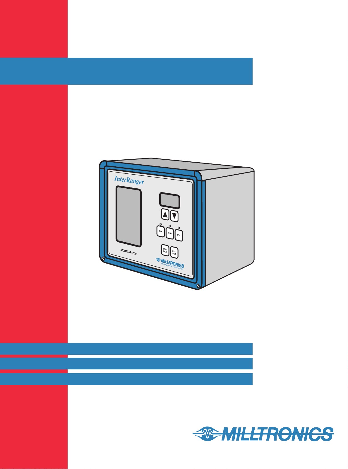
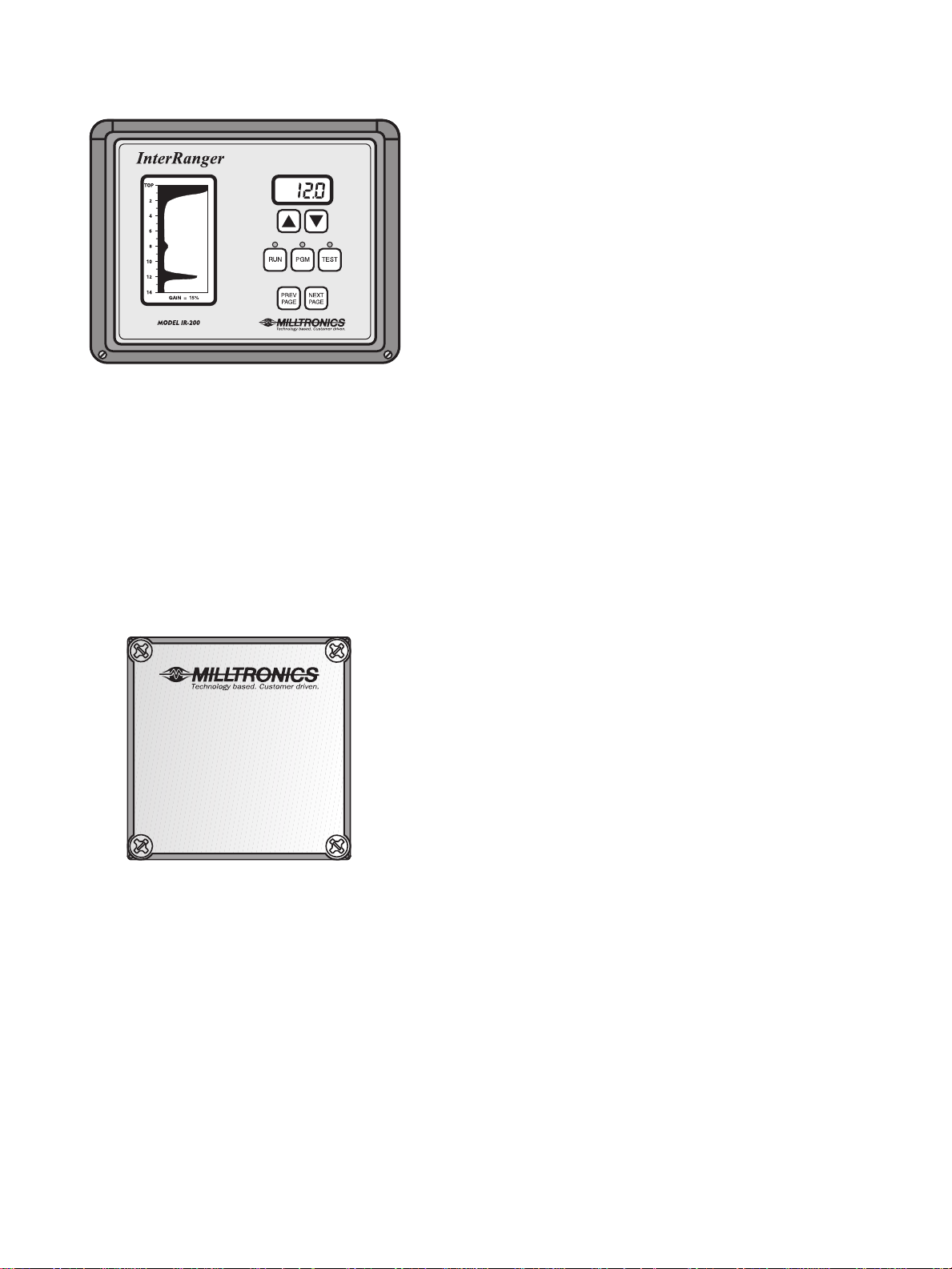
The InterRanger is made up of three main components: the Monitor, the Transceiver, and the Sensor.
The Monitor
displays the current interface level and transmits this information to other equipment.
The Transceiver
drives the ultrasonic Sensor and transmits the echo signals to the Monitor.
The Sensor
sends out the ultrasonic pulses through the liquid medium and receives the echoes.
PL-545 5 InterRanger IR-200
Page 6
IR-200 MONITOR
HEATER FOR MONITOR
Description
The Monitor is housed in a fiberglass NEMA 4X enclosure
containing the signal analysis, display, and control circuitry
for the system. All configuration and parameter changes are
made from the membrane keypad on the front panel of the
Monitor.
Temperature Range
-10°C to 50°C (14°F to 122°F)
-30°C to 50°C (-22°F to 122°F) with optional heater
Drawing
0-8130003Z-DU-C
Description
The optional heater should be ordered when the Monitor is to
be located in a climate that drops below -10°C (14°F). The
heater has a built in thermostat so that power consumption is
kept to a minimum. When operating, the heater will consume
an additional 50 watts of power and is available in 115Vac
and 230Vac configurations.
IRP-8D TRANSCEIVER
Description
The Transceiver is housed in a polycarbonate NEMA 4X
enclosure and boosts the Sensor signal enabling it to be
transmitted over standard signal cable for up to 225 m (750’).
For use with the IRT-100D or IRT-100DC Sensor.
Temperature Range
-30°C to 50°C (-22°F to 122°F)
Drawing:
0-8130007Z-DU-B
InterRanger IR-200 6 PL-545
Page 7
IRT-100D SENSOR
IRT-100DC SENSOR
Description
A small, submersible, dual head Sensor constructed of
polyurethane and 316 stainless steel. It is fitted with a 3/4”
NPT nipple and includes 7.5 m (25’) of shielded cable
(optional 22.5 m (75’) available).
Temperature Range
-30°C to 80°C (-22°F to 176°F)
Drawing
0-8140001Z-DU-C
Description
Same as the IRT-100D but is constructed of high
temperature epoxy. Supplied with either a Kynar
stainless steel 3/4” NPT nipple and 7.5 m (25’) of Teflon
®
or 316
®
jacketed cable (optional 22.5 m (75’) available).
Temperature Range
-30°C to 105°C (-22°F to 221°F)
Drawing
0-8140002Z-DU-C
PL-545 7 InterRanger IR-200
Page 8
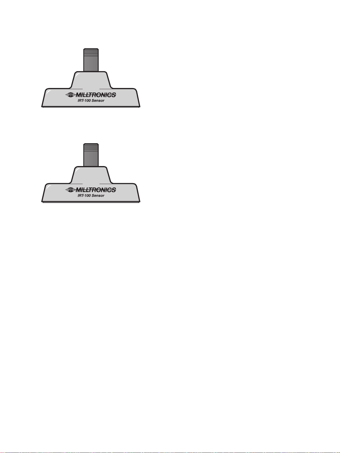
RAIL MOUNT FOR MONITOR
Anodized Aluminum Plate
2” Hand Rail
Description
This anodized aluminum plate allows the Monitor to be mounted on a horizontal or vertical, standard 2” hand
rail. Two 2” U-bolts are supplied and all holes are pre-drilled.
Drawing
0-8130004Z-DU-C
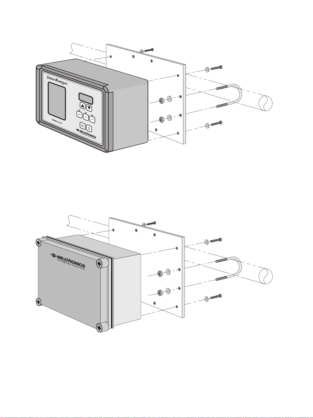
RAIL MOUNT FOR TRANSCEIVER
Anodized Aluminum Plate
2” Hand Rail
Description
This anodized aluminum plate allows the Transceiver to be mounted on a horizontal or vertical, standard 2”
hand rail. Two U-bolts are supplied and all holes are pre-drilled.
Drawing:
0-8130008Z-DU-C
InterRanger IR-200 8 PL-545
Page 9
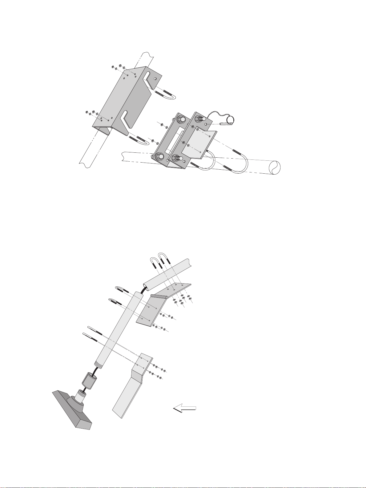
STATIONARY HANDRAIL BRACKET KIT FOR SENSOR
Description
This kit contains a two piece mounting bracket, two 2” U-bolts and two 3/4” U-bolts for suspending an IRT-100
series Sensor from a standard 2” handrail. The 3/4” pipe and coupling needed to connect the Sensor to the
bracket are supplied by the customer.
Drawing
0-8140004Z-DD-C
SWING OUT ADAPTOR KIT FOR SENSOR
Description
This kit contains a swing-out bracket, a skimmer
guard, and six 3/4” U-bolts for use with an IRT100 series Sensor and Stationary Handrail
Bracket. This kit should be used if the tank has a
surface skimmer so that the Sensor deflects out
of the way when the skimmer moves past it.
Drawing
0-8140005Z-DD-C
Skimmer
PL-545 9 InterRanger IR-200
Page 10

STORAGE
All components can be stored in a dry area with a maintained temperature range of -20°C to 50°C
(-4°F to 122°F). The Monitor and Transceiver should be sealed to prevent moisture intrusion in humid areas.
MAINTENANCE
The only part of the InterRanger IR-200 that requires maintenance is the Sensor face and only when it is
subject to algae or scale build-up.
Cleaning of the Sensor face is required is if build up of material exceeds:
» algae or debris: >1.5 cm (1/2”)
» scaling: >0.75 cm (1/4”)
Greater build-ups than these will make it difficult for the Sensor to detect the return echo signal and may result
in incorrect or null readings. The timing of this maintenance is determined by the rate of accumulation and
should be estimated at the installation site.
There is no routine maintenance or calibration procedures that need to be performed on the IR-200
electronics.
InterRanger IR-200 10 PL-545
Page 11

PRINCIPLES OF OPERATION
GENERAL
The InterRanger series utilizes ultrasonic acoustical energy to detect and monitor material interfaces within
liquids. An interface is described as the transition point between two materials with different densities such as
liquid to liquid, liquid to solid, or liquid to suspended-solid.
The IRT-100 series Sensor is suspended just below the surface of the liquid in a vessel and contains a
transmitter and a receiver element. The transmitter emits a burst of ultrasonic energy towards the bottom of
the vessel and the receiver “listens” for the returning echo. The microprocessor based monitoring system
measures the time delay and stores the result in memory. Once enough information has been gathered (over
a user-determined time frame), the Monitor displays a ‘Tank Profile’ on the LCD display. All interfaces
detected are displayed and a user-specified interface will be tracked by the unit and shown in the numerical
display above the keypad.
DEAD ZONES (BLANKING DISTANCES)
Two “dead zones” exist where an interface is difficult or impossible to detect. The first zone exists within 15
cm (6”) of the Sensor face because of interference from the transmitter. Echoes returned from this area are
lost in the “noise.” The second zone is within 2 to 5 cm (1 to 2”) of the tank bottom because weak echoes from
this area are usually overwhelmed by the strong echoes returned by the tank bottom or heavy sediment. This
height of this zone can be adjusted by the user to eliminate the strong echoes and help detect the weaker
echoes.
PL-545 11 InterRanger IR-200
Page 12

InterRanger IR-200 12 PL-545
Page 13

HARDWARE INSTALLATION
EXTERNAL CONNECTIONS
See Drawing 0-8130005Z-DI-C for wiring and connection information.
POWER
The InterRanger Monitor requires 115 or 230 Vac at 50 or 60 Hz and consumes up to 30 W of power. If the
optional heater is installed, an additional 50 W of power will be used when the heater is operating. Be sure
that the “voltage selector” switch is in the appropriate 115 V or 230 V position before turning the unit on. The
Voltage Selector switch, the On/Off switch and two 2 A fuses are located in the bottom left corner of the
Monitor enclosure.
Do NOT apply power to the unit without the Sensor connected.
Damage to the Transceiver may result.
4 - 20 mA
An isolated 4 to 20 mA output is provided which will drive loads up to 900 ohms.
Calibration of “zero” and “span” is done using the ‘TEST’ mode. (See Test Mode on page 28). Adjustment of
“zero” and “span” for the level is done in the ‘PGM’ mode. (See
alarm condition, the output will drop below 4 mA and cause an “underflow alarm” to alert any external devices
that use this output.
Program
Mode on page 21) When in an
SET POINT RELAYS
Four “Form C” relays are available for set point control outputs with relay contacts rated for 7A resistive load
at 250 Vac. Each relay can be programmed to perform as either a high or low alarm and the hysteresis for
each is adjustable.
See
RELAY NUMBER x FUNCTION
ALARM RELAY
A fifth “Form C” relay can only be used to remotely indicate the existence of an error condition and is rated for
7A resistive load at 250 Vac. This relay is wired to be energized in the NO ALARM state with the normally
open contacts closed for normal operation. The unit will enter an alarm condition if power is lost.
SERIAL COMMUNICATIONS
The IR-200 provides both RS-232-C and RS-485 communication capability with a DOS-based PC that has
640K of base memory and DOS 4.01 or higher. Up to 40 IR-200’s can be monitored using RS-485 and
appropriate wiring.
Only one type of communication: RS-232 or RS-485 can be used at a time.
on page 27 for more information.
PL-545 13 InterRanger IR-200
Page 14

IR-200 MONITOR
The IR-200 Monitor is normally mounted near, or on, the tank that it is tracking, usually with the Milltronics
Rail Mount assembly (See drawing 0-8130004Z-DU-C).
Ensure that the voltage selector switch inside is set for the power available to the unit and that liquid-tight
connectors are used to seal all wires entering the enclosure.
All electrical connections must be made before turning the unit on.
faceplate and use the white power switch.
To turn on the unit, open the
IRT-100 SERIES SENSOR
The IRT-100 series Sensors must be suspended in a liquid in order to work.
The face of the Sensor should be placed about 5 cm (2”) below the surface of the liquid. It may be suspended
lower than that if conditions dictate, but there is no performance advantage.
The easiest method of installation is to use one of the Milltronics Handrail Brackets in conjunction with a piece
of 3/4” stainless steel or galvanized pipe and a 3/4” pipe coupling. If the monitored tank has any type of
surface skimming mechanism then the Milltronics Swing-out Adapter should be utilized. (See drawings 08140003Z-DD-B, 0-8140004Z-DD-C, and 0-8140005Z-DD-C.)
They will NOT work through air.
IRP-8D TRANSCEIVER
The IRP-8D Transceiver may be located up to 225m (750’) from the Monitor and 22.5m (75’) from the Sensor.
It can also be mounted on a tank railing using the Milltronics Transceiver Rail Mount assembly. (See drawing
0-8130007Z-DU-B )
All wiring connections must be made before power is applied to the unit to avoid damaging the
(See drawing 0-8130005Z-DI-C or 0-8130006Z-DI-C depending on your Sensor.) Ensure that
Transceiver
liquid-tight connectors are used to seal all wires entering the enclosure.
InterRanger IR-200 14 PL-545
Page 15
QUICK START
CONFIGURING THE UNIT
This procedure should be completed to configure the unit, locate the tank bottom, and prepare the unit for
normal operation.
1
2
3
4
5
6
7
O/I The first time a unit is turned on, it will be in an alarm condition. A
message will be displayed explaining that the unit will not operate until
the tank depth has been programmed. (If this error message is not
displayed, it means that a tank depth value has already been entered
and only the RUN light will be lit.)
Press the program key the enter the PROGRAM Mode of operation. A
screen requesting the TANK DEPTH is displayed.
Press the next page key once to advance to the DISPLAY FORMAT
screen.
Use the up arrow key to select a value of 4, clear water depth in meters,
or 3, clear water depth in feet.
Press the next page key twice to advance to the ECHO PROFILE
UPDATE RATE screen.
Press the down arrow key until you select a value of 1 (7.5 sec).
Press the next page key once to advance to the INTERFACE LEVEL
AVERAGING CYCLES screen.
8
9
10
11
PL-545 15 InterRanger IR-200
Press the down arrow key until you select a value of 1.
Press the previous page key four times to return to the TANK DEPTH
screen.
Press the up or down arrow keys to enter a tank depth that is at least
0.6m (2’) greater than the actual tank depth. By setting this value too
deep we are able to test that the InterRanger is performing correctly as
it will detect a strong echo at the true tank bottom.
After the TANK DEPTH has been set, press the run key. While the unit
adjusts transmitter power to the tank conditions, the displays will go
blank for a few minutes.
This is normal.
Page 16
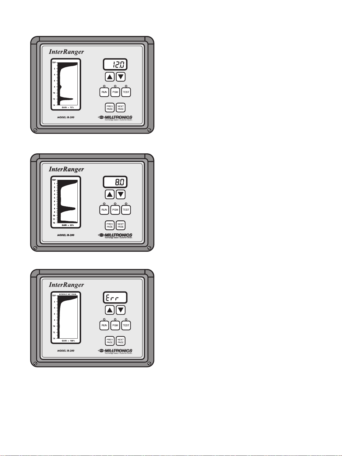
Figure 1
DETERMINING TANK DEPTH
The graph that appears in the LCD display shows numbers
along its side indicating depth in feet. A peak appearing at
any place on the display indicates an interface at that
depth. The larger the peak, the stronger the echo returned
and the more distinct the interface.
For example, if we are measuring a tank with a 12 foot
depth we would initially test the unit with a TANK DEPTH
setting of 14 feet. This setting will give us a strong echo at
12 feet (Figure 1).
At this point there are two ways of determining the TANK
DEPTH:
– Detection of tank bottom at 12 feet
From the Test Echo Profile
Look at the profile displayed and check for a large peak on
the graph where you would expect the bottom to be. Write
down this number so that it can be entered later. This is the
easiest method of determining the tank depth but it can be
in error if there are thick solids at the bottom of the tank
which return a strong echo.
Figure 2
– Detection of interface at 8 feet
Figure 3
– Error condition
Physical Measurement
If the bottom is not visible on the graph, or no major peaks
appear where expected, this usually means that the solids
are very thick on the bottom or that the tank bottom is
sloped. In this case carefully measure the distance between
the Sensor face and the bottom of the tank to obtain your
TANK DEPTH measurement. This is the preferred method
of measurement because it is the most accurate.
In the example we then change the TANK DEPTH to 12
feet (your value is determined by your tank depth and
sensor placement). The InterRanger IR-200 now takes the
next-largest peak and scales it to 80% of the chart range
(Figure 2). In the example this peak is at the 8 foot mark
and is most likely the interface of interest for us. This
automatic scaling is only available if the GAIN CONTROL is
set to 0. (See GAIN CONTROL on page 25.)
If the graph is a flat line with GAIN=100% (Figure 3) then
there is a problem in the wiring, the Sensor placement, or
tank conditions are completely upset and no interface can
be detected.
InterRanger IR-200 16 PL-545
Page 17

Now that basic operation of the unit has been verified, the critical parameters can be reprogrammed to
produce a true profile.
12
13
14
Press the program key and then the next page key to advance to the
DISPLAY FORMAT screen. When changing program parameters,
DISPLAY FORMAT must be changed first (if necessary) because this
setting affects all of the measurements used in the InterRanger. The
TANK DEPTH must be re-entered whenever the DISPLAY FORMAT is
changed.
Press the up or down arrow keys to select the measurement units and
information displayed.
If you choose to display “5 = sludge depth as % of tank” then all
measurements must be made in feet.
Use the previous page key to return to the TANK DEPTH screen and
press the up or down arrow key to enter the value determined during
the Initial test.
If you have not yet determined the depth of the tank, which is really the
distance from the Sensor face to the tank bottom, then return to
Configuring the Unit
on page 15.
Now use the next page key to scroll forward through the other
parameters and the up and down arrow keys to set the following values
listed. These are good starting points for most applications and can be
fine tuned later. Each of the following parameters is described in more
detail in
Parameters
on page 23.
15
Parameter Example Setting
Trend Graph Time Scale 1
Echo Profile Update Rate 4
Interface Level Avg. Cycles 10
Trigger Point 1
Trigger on Peak or Leading Edge 1
Median or Average 1
Sensitivity 8
Bottom Dead Zone 0.4’ (0.1 m)
Top Dead Zone 1.0’ (0.3 m)
Gain Control 0
Maximum Transmit Gain 100
Bottom Echo In Gain Control 0
AGC Exclusion 0
Speed of Sound Correction 1.000
Lost Interface Control 1
Press the run key to begin operation.
The graphical display will update after the amount of time set in the
ECHO PROFILE UPDATE RATE (1 minute in the example). The
numeric display will update after the graphical display has updated the
number of times specified in the INTERFACE LEVEL AVERAGING
CYCLES (10 in the example). This would mean that the numeric display
would update after 10 minutes if the settings from the example are used
(1 minute times 10 cycles). Press the PGM key at any time to return to
the PROGRAM mode for further parameter adjustments.
PL-545 17 InterRanger IR-200
Page 18

InterRanger IR-200 18 PL-545
Page 19

OPERATION
RUN MODE
This is the normal operation mode of the InterRanger. While running, it does the following:
» Displays a graphical profile of the tank being monitored which indicates all interfaces present
in that tank
» Detects, monitors, and displays the depth of the selected interface
» Opens or closes the relays depending on their configuration
The InterRanger starts in RUN mode. This allows the unit to keep functioning if the power fails and then
resumes.
GRAPHS
There are two display formats available for viewing while in the RUN mode described below. Use the
page
and
previous page
keys to switch between the two graphs.
shows the Echo Profile Graph (default at startup).
shows the Trend Graph.
next
PL-545 19 InterRanger IR-200
Page 20

ECHO PROFILE GRAPH
The ‘Echo Profile Graph’ provides the operator with a
cross-sectional profile of the tank being monitored. The
graph depicts the relative strength of all echoes returned
from the tank and indicates the depth at which they occur.
By reducing the update time of the graph to it’s lowest
setting (1 = 7.5 seconds) the operator can view changes
in the tank as they happen. For normal operation this
setting (ECHO PROFILE UPDATE RATE) should be set
to 3 (30 seconds) or 4 (1 minute).
The Echo Profile Graph is the default screen that appears
when RUN Mode is enabled.
In the event that the InterRanger cannot detect an
interface level, ‘Err’ will appear in the numeric display and
the graphical display will continue to show the echo profile
with ‘Interface Not Found’ displayed at the top of the
screen.
TREND GRAPH
This display is a “virtual strip chart recorder” showing the
level of the interface being monitored over the last 3, 6,
12 or 24 hour period (TREND GRAPH TIME SCALE
parameter).
This graph gives the operator an overview of how the
interface of interest fluctuated over the selected time
scale. This information is useful when the tank is
inspected on a daily basis.
InterRanger IR-200 20 PL-545
Page 21

PROGRAM MODE
The PGM Mode is used to adjust and fine tune the InterRanger Monitor for use in different applications. To
access this mode, press the PGM key while in the normal RUN Mode. All measurement operations will cease
and the graphical display will show “help screens” for each parameter as it is selected.
For a more complete description of each parameter setting, see
parameter settings are accessed by using the PREV PAGE and NEXT PAGE keys while in the PGM Mode.
The digital display shows the current setting for each program parameter. These values are adjusted by using
the up and down arrow keys. Hold down the appropriate arrow key to scroll through the available values
quickly.
Parameters may be adjusted in any order except for DISPLAY FORMAT. Whenever DISPLAY FORMAT is
changed all other parameters which specify distance must also be changed. These parameters return to their
defaults:
» Bottom Dead Zone
» Top Dead Zone
» Relay Number x Function
» Relay Number x “On” Setpoint
» Relay Number x “Off” Setpoint
Parameters
on page 23. The various
PL-545 21 InterRanger IR-200
Page 22

InterRanger IR-200 22 PL-545
Page 23

PARAMETERS
PROGRAM MODE
TANK DEPTH
This is the distance between the Sensor face and the bottom of the tank directly below it. It is important that
this parameter be set correctly in order for the unit to display accurate readings.
See
Configuring the Unit
Values: 0.00 to 30.00m (0.0 to 100.0’)
DISPLAY FORMAT
The numeric display will show the level of the interface being monitored in reference to the bottom (sludge
depth) or top (clear water) of the tank. Measurements can be viewed in meters or feet.
Values: 1 = Depth of sludge, in feet
2 = Depth of sludge, in meters
3 = Amount of clear water, in feet
4 = Amount of clear water, in meters
5 = Depth of sludge, as a percentage of the total tank depth
If option 5 is selected then all measurements
TREND GRAPH TIME SCALE
This sets the time span desired for the Trend Graph. The clock for the graph may be set in TEST Mode. See
Test Mode on page 29.
Values: 1 = 3 hours
2 = 6 hours
3 = 12 hours
4 = 24 hours
on page 15 for more detailed information.
be made in feet.
must
ECHO PROFILE UPDATE RATE
The IR-200 transmits approximately four times per second. Each of these transmit pulses produces an echo
profile of the tank. If these profiles were analyzed individually, “noise” due to passing debris and other
disturbances would yield inconsistent results. The IR-200 averages a group of these profiles based on a user
defined time period to provide an average profile. The longer the time period selected, the more defined the
displayed tank profile will be despite any noise that may be present. The 3 (30 second) or 4 (1 minute) time
period should be used whenever possible as this will provide the most noise free profile.
This parameter determines how quickly the Echo Profile Graph is updated.
Values: 1 = 7.5 seconds
2 = 15 seconds
3 = 30 seconds
4 = 1 minute (standard)
PL-545 23 InterRanger IR-200
Page 24

INTERFACE LEVEL AVERAGING CYCLES
After the IR-200 has compiled an average echo profile (ECHO PROFILE UPDATE RATE), it is analyzed and
the specified interface level (TRIGGER POINT) is determined. This parameter sets the number of average
echo profiles that are used to determine the average specified interface level.
This parameter determines how quickly the numeric display is updated.
Values: 1 to 99
TRIGGER POINT
This parameter is used to specify which interface is to be tracked. This interface level is shown on the digital
display while in the RUN Mode and is the one charted on the Trend Graph. More than one interface will often
exist in a vessel so it is important to specify which one is monitored.
Values: 1 = Track the largest peak. This indicates the point in the tank where the density changes by
the greatest amount. In most cases, this is the interface of interest and therefore this is the
standard setting.
2 = If there is a smaller peak just above the largest peak, track it. This setting is used to track
the heaviest “fluff” layer that may be suspended just above the thick blanket.
3 = Track the peak closest to the bottom of the tank, regardless of size. This setting generally
works well in gravity thickeners.
4 = Track the peak closest to the top of the tank. This setting will track the very lightest fluff in
the tank.
5 = This special algorithm can be used in tanks where the heaviest sludge never exceeds
0.5% solids. It tracks the beginning of any “mound” at the bottom of the tank.
6 = This algorithm is designed primarily for the special case of coal mine washer tanks. It is
designed to track any interface that absorbs sound, rather than one that reflects sound.
TRIGGER ON PEAK OR LEADING EDGE
This setting determines at which place on the echo profile the unit interprets the interface to be. This
parameter only applies to TRIGGER POINT values of 1, 2, or 3.
Values: 1 = Peak of echo profile
2 = Leading edge of echo profile
MEDIAN OR AVERAGE
This parameter determines whether the dampening done by the INTERFACE LEVEL AVERAGING CYCLES
parameter is accomplished through an averaging or a median type algorithm. In general, set this value to 1 for
‘averaging’. Use a value of 2, ‘median’, for cases where the tank has bottom rakes but no surface skimmers.
These cases can produce numbers in which some of the results are inaccurate. The median method
eliminates these numbers from consideration.
Values: 1 = Averaging
2 = Median
InterRanger IR-200 24 PL-545
Page 25

SENSITIVITY
This parameter should almost always be set to 8. This value determines the minimum peak size that the IR200 will recognize when compiling echo profiles. A smaller value would mean that smaller peaks would be
recognized. If TRIGGER POINT is set to 6, it will probably be necessary to change this parameter to a value
of 5 or 6 to achieve consistent results.
Values: 1 to 50
BOTTOM DEAD ZONE (BOTTOM BLANKING DISTANCE)
It is often a good idea to define a small area just above the bottom of the tank for the IR-200 to ignore. Most
tanks have a layer of mud at the bottom that the rakes do not disturb. To avoid tracking this mud, a dead zone
can be established. This value is entered in meters or feet depending on the DISPLAY FORMAT selected. A
good standard value is 0.12 m (0.4’).
Values: 0.00 to 30.00 m (0.0 to 100.0’)
TOP DEAD ZONE (TOP BLANKING DISTANCE)
This parameter defines a zone at the top of the tank that the IR-200 will ignore. This value is entered in
meters or feet, depending on the DISPLAY FORMAT that is selected. The value should be set at 0.21 m (0.7’)
to avoid triggering from the noise that the transmit pulse generates. This “noise”can be seen at the top of the
echo profile.
Values: 0.00 to 30.00 m (0.0 to 100.0’)
GAIN CONTROL
When this value is set to 0, the IR-200 will adjust transmitter power automatically. The automatic gain control
(AGC) will adjust the power level so that the biggest peak in the echo profile is about 80% of full scale on the
display graph. This automatic mode is well suited for tanks where Sensor fouling is likely to occur. As the
Sensor becomes fouled, the unit will increase the gain in order to maintain the profile image.
It might be desirable to set up a fixed power level in some applications. By setting this parameter to a number
between 1 and 100 and watching the effect upon the echo profile in the graphic display, the desired level can
be selected.
If the TRIGGER POINT value is set to 6, the gain control must be given a set value by the user as the
AGC will not work in this situation.
Values: 0 to 100%
MAXIMUM TRANSMIT GAIN
Another method of preventing the unit from tracking subtle interfaces when the main interface is removed or
lost, is to limit the power of the transmitter. To use this parameter, first set the GAIN CONTROL to 0
(automatic). Then, set this parameter to the largest transmit power level desired (1 to 100). The AGC’s
maximum range is now limited to this number. Normally this number is set to 100%.
Values: 0 to 100%
PL-545 25 InterRanger IR-200
Page 26

BOTTOM ECHO IN GAIN CONTROL
With this parameter set to 0, the AGC adjusts transmitter power based upon the size of the largest interface
peak only, and ignores the size of the tank bottom peak. When this code is set to 1, the AGC will be adjusted
based upon the size of the biggest peak even if that happens to be the tank bottom. This alternate method of
control is used in tanks with very thick sludge that may be drawn off completely on occasion. If the tank
bottom echo is roughly the same size as the interface echo, this prevents the AGC from going too high when
the sludge is drawn off. This method has the advantage over the ‘fixed gain’ method because it will still
compensate for a fouled Sensor automatically. If GAIN CONTROL is not set to 0, then this parameter has no
effect.
Values: 0 = exclude tank bottom from gain control (default)
1 = include tank bottom in gain control
AGC EXCLUSION
This parameter can be helpful if the IR-200 is being used to track the level of a light fluff layer instead of the
main “heavy” layer in the tank. (See TRIGGER POINT = 2 or 4). Normally, if the GAIN CONTROL is set to 0
in these cases, the unit will adjust its gain until the main interface peak is clearly visible, and the fluff layers
will appear as small peaks. Adjusting this parameter can increase the size of the smaller peaks, thereby
improving the reliability of the detection process. The value entered should be the approximate width of the
main peak, entered in tenths of a foot. The unit will then ignore the main peak when adjusting transmit power.
Values: 0 to 100%
SPEED OF SOUND CORRECTION
In typical ambient temperature wastewater tanks, this value should be left at its default value of 1.000. In
industrial applications where the medium is not pure water or is some other liquid, this value may require
adjustment so that the instrument scales the echo profiles accurately. If the speed of sound is known for the
liquid in the tank, divide the speed by 5000 ft/sec and enter this result. If the speed of sound is not known,
adjust this value by trial and error. With each trial, attempt to bring the “tank bottom” peak into its correct
position.
As a general guideline, water that is warmer than 50°C (122°F), will probably require compensation.
Values: 0.000 to 9.999
LOST INTERFACE CONTROL
If this parameter is set to its default value of 1, the IR-200 will report an error condition if it cannot find an
interface in the echo profile. If this parameter is set to 0, then the IR-200 will assume that, if no interfaces can
be found in the profile, the blanket has been drawn off completely, and report an interface level of 0. If this
option is used, be aware that a reading of 0 may be due to a fouled Sensor, or a completely upset tank.
Values: 0 = display no interfaces
1 = display error (default)
InterRanger IR-200 26 PL-545
Page 27

SERIAL ADDRESS
The SERIAL ADDRESS is used as an ID code if the IR-200 is attached to a host computer through the RS232 or RS-485 port. If more than one unit is connected to the computer’s serial port, each unit must have its
own unique address. If no units are connected to the serial port then this parameter has no effect. See
Communication Protocol on page 31 for a complete description of the serial port protocol.
Values: 1 to 99
BAUD RATE
This parameter sets the speed of the data exchange between the IR-200 and the host computer. This value
must match the speed setting of the host computer’s serial port. If communication is made over long distances
or if there is a lot of electrical noise present, a lower baud rate may be needed for reliable communication.
Values: 1 = 19200 bits per second
2 = 9600 (recommended)
3 = 4800
4 = 2400
5 = 1200
6 = 600
7 = 300
4 mA LEVEL
This parameter sets the interface level (as shown in the digital display) that will cause a 4mA reading at the
current output terminals. Think of this value as the “zero offset” for the current reading. For example, if the
specified interface level is needed to span the 4 to 20 mA range between 2 m and 4 m (6.6’ to 13.1’), then set
this value at 2 (6.6) and set the next parameter (20 mA LEVEL) at 4 (13.1). Then, for levels of 2 m (6.6) or
less, the reading will be 4 mA and levels of 4 m (13.1’) or higher will read 20 mA. An interface level of 3 m
(9.85’) will produce a reading of 12 mA. It is possible to set the 4mA level higher than the 20 mA level to
achieve a “reversed” span. This value is in meters or feet, depending upon the DISPLAY FORMAT parameter
setting.
Values: 0.00 to 30.00 m (0.0 to 100.0’)
20 mA LEVEL
This parameter sets the interface level (as shown in the digital display) that will cause a 20mA reading at the
current output terminals. Units are determined depending on the DISPLAY FORMAT parameter. (See 4mA
LEVEL parameter).
Values: 0.00 to 30.00 m (0.0 to 100.0’)
RELAY NUMBER X FUNCTION
The IR-200 has four relays that may be set-up individually as ‘high’ or ‘low’ alarms with different setpoints.
(Use RELAY NUMBER x ‘ON’ SETPOINT and RELAY NUMBER x ‘OFF’ SETPOINT to set these levels.)
Set this parameter to 0 to activate the relay for interface levels lower than the setpoint described. Set it to 1 to
activate the relay for interface levels higher than the setpoint.
Values: 0 = Low Alarm
1 = High Alarm
PL-545 27 InterRanger IR-200
Page 28

RELAY NUMBER X ON SETPOINT
This is the point at which the corresponding relay will trip. If the relay is a ‘high’ alarm, it will activate when the
specified interface level goes higher than this value. If the relay is a ‘low’ alarm, it will activate when the
specified interface level goes lower than this value. The value is in meters or feet depending on the DISPLAY
FORMAT parameter.
Values: 0.00 to 30.00 m (0.0 to 100.0’)
RELAY NUMBER X OFF SETPOINT
To allow for hysteresis in the activation of the relays, this parameter sets the reading that must be reached in
order to turn a relay ‘off’ after it has been turned ‘on’. Once the corresponding relay has been turned on, (see
RELAY NUMBER x ‘ON’ SETPOINT), it will not turn off until the specified interface level reaches the value set
in this parameter. The value is in meters or feet depending on the DISPLAY FORMAT parameter.
Values: 0.00 to 30.00 m (0.0 to 100.0’)
InterRanger IR-200 28 PL-545
Page 29

TEST MODE
This mode is used to check the operational status of the unit, calibrate the 4-20 mA output and set the time in
the trend graph clock.
1
2
Press the
Press the
different test procedures.
SET MINUTE
adjustment of minutes for Trend Graph clock
SET HOUR
adjustment of hours for Trend Graph 24 hour clock
DISPLAY TEST
lights all LED’s and LCD segments
4 mA ADJUST
fine tuning of 4 mA output
20 mA ADJUST
fine tuning of 20 mA output
RELAY X TEST
independent testing of all relays
ALARM RELAY TEST
testing of alarm relay
PRINT PROFILE
prints echo profile on serial printer
key to begin test mode.
test
next page
and
previous page
keys to scroll through the
3
4
5
6
Press the
Press the up and
while it is running.
Press the
select another test.
Press the
key again to run the selected test.
test
down arrow
key again to return to the test mode so that you can
test
key to return to run mode.
run
keys to change the settings for any test
PL-545 29 InterRanger IR-200
Page 30

SECURITY “LOCKOUT” FOR PGM AND TEST MODES
The PGM and TEST Modes may be ‘locked out’ so that unauthorized changes cannot be made to the
InterRanger. Open the front panel of the Monitor and locate the Processor PC card on the backside of the
front panel behind the graphic display.
There are four DIP switches on this card. For complete access to the PGM and TEST Modes, the switches
must be in the following (factory) setting:
Switch Status
1OFF
2ON
3ON
4OFF
If these switches are set any other way, only the RUN Mode will function.
InterRanger IR-200 30 PL-545
Page 31

IR-200 COMMUNICATION PROTOCOL
Communication Protocol 33
Introduction 33
Electrical Interface 33
Data Format 33
Network Control 33
Message Format 35
Start Character 35
Instrument Address Field 35
Data Length Field 35
Data Field 35
Checksum Field 36
Error Handling 37
No Reply Error 37
Incomplete Message Error 37
Hardware-Related Errors 37
Data Transmission Errors 37
Model IR-200 Messages 39
Host-Originated Messages 39
Request Data Report 39
Request Tank Profile 39
Request Relay Configuration 40
Request Trend Data 40
Request Program Parameter Value 40
Change Program Parameter Value 41
Change Mode 41
Program Parameter Numbers 42
MODEL IR-200 ORIGINATED MESSAGES 43
Data Report 43
Tank Profile 44
Relay Configuration 45
Trend Data 46
Program Parameter Report 46
Negative Acknowledge 47
PL-545 31 InterRanger IR-200
Page 32

InterRanger IR-200 32 PL-545
Page 33

COMMUNICATION PROTOCOL
INTRODUCTION
The protocol defined in this document is used for all communications between a host computer and an
InterRanger IR-200. The protocol allows the host computer to interrogate the unit to obtain information
regarding the operation of the instrument. The computer may also program and control the operation of the
IR-200 remotely.
ELECTRICAL INTERFACE
The host computer communicates with the Model IR-200 through the Monitor’s built-in serial port, using either
an RS-485 or RS-232 electrical interface. When using the RS-485 interface, instruments may be multidropped
on a single communications line. When using the RS-232 interface, though, only a single instrument may be
connected on a communications line (unless suitable modems or other communications devices are used).
DATA FORMAT
A serial byte-oriented asynchronous protocol is used. Each data byte is transmitted in a data frame containing
a single start bit, eight data bits, no parity bits, and one stop bit. The data bits are transmitted with the least
significant bit first. Non- return-to-zero (NRZ) data encoding is used. BAUD rate is adjustable using the
Monitor’s program parameters.
NETWORK CONTROL
Communication between the host computer and each of the remote instruments takes place as a series of
half-duplex message exchanges. The host computer initiates all message exchanges. Remote instruments
may only transmit in reply to a host-initiated message.
PL-545 33 InterRanger IR-200
Page 34

InterRanger IR-200 34 PL-545
Page 35

MESSAGE FORMAT
The protocol uses ASCII-encoded data. Each data byte is sent as two ASCII-encoded hexadecimal (0-9, A-F)
digits, most significant digit first. The two ASCII characters “OO” would represent a byte value of zero, while
the two ASCII characters “80” would represent a byte value of 128 decimal.
Each message consists of the following fields:
» Start character
» Instrument address
» Data length
» Data
» Checksum
START CHARACTER
The start character is the single ASCII character “M” for messages which originate at the host computer and
the single ASCII character “R” for messages which originate at remote instruments.
INSTRUMENT ADDRESS FIELD
The instrument address field of the message is used in host-originated messages to indicate to which
instrument the message is directed. It is used in instrument-originated messages to indicate which instrument
is replying to the host-originated message.
The instrument address field is one byte long. It is transmitted as two ASCII-encoded hexadecimal digits
(“OO” to “FF”).
DATA LENGTH FIELD
The data length field specifies how many bytes of data are part of a particular message’s data field.
The data length field is normally one byte long. It is transmitted as two ASCII-encoded hexadecimal digits
(“O1” to “FF”).
However, if a message length will exceed 255 characters, a 3 byte data length is transmitted. In this case, the
first byte will always be a “00”. This should alert the receiving equipment that the message length will exceed
255 characters, and a 2 byte data length will follow. The 2 byte data length will range from “0100” to “FFFF”.
DATA FIELD
The data field contains the “information” content of a message. The first byte of the data field indicates the
message type. Additional bytes in the data field provide the data applicable to each of the message types.
Different message types are defined to perform different functions. The message types that are defined for
the blanket level detector are defined later in this document.
PL-545 35 InterRanger IR-200
Page 36

CHECKSUM FIELD
The checksum field is used to detect errors that may occur in the transmission of a message. It is calculated
as the 16- bit sum of all previous byte values (the value of a two hexadecimal digit pair), excluding the start
character.
The checksum field is two bytes long. It is transmitted most-significant byte first, as four ASCII-encoded
hexadecimal digits (“OOOO” to “FFFF”).
InterRanger IR-200 36 PL-545
Page 37

ERROR HANDLING
The following types of errors can occur during the transmission of a message:
» No reply received when expected
» Incomplete message received
» Hardware-related errors, such as framing errors and overrun errors
» Data transmission errors.
NO REPLY ERROR
A remote instrument must reply to all messages that are sent to it. If the remote instrument doesn’t reply
within a specified time limit (the no reply timeout), the host computer will detect a no reply error. Upon
detection of the no reply error the host computer may retransmit its request to the remote instrument, if
desired.
The no reply timeout is two seconds.
INCOMPLETE MESSAGE ERROR
The expected length of a message can be determined by knowing the length of each of the fields in the
message. The length of the data field of the message is specified by the data length field in the message.
Once reception of a message has begun, each character of the message must be received within a certain
time after the preceding character. This time is called the intercharacter timeout. If the next character of the
message is not received within the intercharacter timeout, an incomplete message error is declared. Remote
instruments ignore any incomplete messages. If the host computer receives an incomplete message, it may
retransmit its request to the remote instrument, if desired.
The intercharacter timeout is 500 milliseconds.
HARDWARE-RELATED ERRORS
If any hardware-related errors are detected during the receipt of a message, the message must be ignored.
Remote instruments will ignore any further characters that are received until a valid start character is
received. The host computer will ignore any further characters that are received until an incomplete message
error is declared.
DATA TRANSMISSION ERRORS
Data transmission errors are detected by checking the checksum field of the message. If the transmitted
checksum does not match the checksum calculated on the received data, a data transmission error is
declared.
Messages with data transmission errors must be ignored. if the host computer receives a message that
contains a data transmission error, it may retransmit its request to the remote instruments, if desired.
PL-545 37 InterRanger IR-200
Page 38

InterRanger IR-200 38 PL-545
Page 39

MODEL IR-200 MESSAGES
HOST-ORIGINATED MESSAGES
The following host-originated messages are defined for the Model IR-200:
» Request Data Report
» Request Tank Profile
» Request Relay Configuration
» Request Trend Data
» Request Program Parameter Value (optional)
» Change Program Parameter Value (optional)
» Change Analyzer Mode (optional)
REQUEST DATA REPORT
A request Data Report message directs the Model IR-200 to transmit a data report to the host. The data
report contains the following information:
» Error status
» Relay status
» Instrument scale
» Trigger priority (1 to 6)
» Profile averaging time
» Tank depth
» Current blanket level
The message is formatted as follows:
Data Length: $01
Message Type: $01
Additional Data: none
Expected Reply: Data Report
Example: The string “M0201010004” requests a data report from a unit answering to address “02”. (The final
“0004” is the checksum)
REQUEST TANK PROFILE
A request Tank Profile message directs the Model IR-200 to transmit a tank profile to the host. The tank
profile indicates the strength of the return signal at various depths in the tank.
The message is formatted as follows:
Data Length: $01
Message Type: $02
Additional Data: none
Expected Reply: Tank Profile
Example: The message string “M0401020007” will request a unit answering to address “04” to send a tank
profile data message.
PL-545 39 InterRanger IR-200
Page 40

REQUEST RELAY CONFIGURATION
A Request Relay Configuration message directs the Model IR-200 to transmit information on its four setpoint
relays. The following information is transmitted for each relay:
» High/low selection
» Relay on value
» Relay off value
The message is formatted as follows:
Data Length: $01
Message Type: $03
Additional Data: none
Expected Reply: Relay Configuration
Example: The message string “M0101030005” will request a unit with address “01” to send a relay
configuration message.
REQUEST TREND DATA
A request Trend Data message directs the Model IR-200 to transmit a string of data equal to the interface
level value over the past x hours, where x is 3, 6, 12, or 24. The IR-200 will always respond with 180 data
points, so the resolution varies with the length of time requested.
The request message is formatted as follows:
Data Length: $02
Message Type: $04
Additional Data: $00 = 1 minute resolution (3 hours)
$01 = 2 minute resolution (6 hours)
$02 = 4 minute resolution (12 hours)
$03 = 8 minute resolution (24 hours)
Expected Reply: Trend Data
Example: A message string “M070204030010” will request a unit answering to address “07” to transmit the
previous 24 hours worth of trend data at a resolution of 8 minutes.
REQUEST PROGRAM PARAMETER VALUE
This message instructs the Model IR-200 to report the current value of a selected program parameter. The
values must be requested by parameter number. The table in
Program Parameter Numbers
on page 42
relates the parameter number to the parameter name. Program parameter descriptions and legal values are
described in the main section of the Model IR-200 operator’s manual. The message is formatted as follows:
Data Length: $02
Message Type: $05
Additional Data: The parameter number to be reported
Expected Reply: Program Parameter Report Message
or a Negative Acknowledge Message
Example: If the host computer would like to request the value of the GAIN CONTROL parameter (parameter
number 11 or 0B hexadecimal) from analyzer number 1, then the host should transmit the ASCII string
“M0102050B0013”.
InterRanger IR-200 40 PL-545
Page 41

CHANGE PROGRAM PARAMETER VALUE
This message is used by the host computer to change the program parameter values stored in the Model IR200 Monitor. The message is formatted as follows:
Data Length: $04
Message Type: $06
Additional Data: Byte $02 = Parameter Number
Byte $03 = MSB of the Parameter
Value
Byte $04 = LSB of the Parameter
Value
Expected Reply: Acknowledge Message or Negative
Acknowledge Message
Parameter values to be transmitted must all be encoded as a 16 bit binary number, then transmitted as two
hexadecimal bytes in ASCII format. Any value which normally includes a decimal point (tank depth, relay set
point values, etc.) must be multiplied by 10, 100, or 1000 (as necessary) to remove the decimal point before
converting to a 16 bit hexadecimal number.
Examples: To transmit a tank depth (parameter number 1) of 11.2 feet, the host must transmit the
hexadecimal equivalent of 112, or $0070. The complete message to IR-200 number 1 would
be “M010406010070007C”.
To transmit a tank depth of 2.45 meters, the host must transmit the hexadecimal equivalent of
245, or $00F5. The complete message to IR-200 number 2 would be “M0204060100F50102”.
To transmit a speed of sound correction factor (parameter number $0F) of 1.180, the host
must transmit the hexadecimal equivalent of 1180, or $049C. The complete message to IR200 number 2 would be “M0204060F049C00BB”.
To transmit a GAIN CONTROL (parameter number $0B) value of 75%, the value would be
encoded as $004B. The complete message to analyzer number 1 would be
“M0104060B004B0061”.
Some program parameters, such as GAIN CONTROL and TANK DEPTH, may be changed by the host
computer while the Monitor is in either the RUN or PGM modes of operation. For these parameters, the new
value will take affect automatically when the IR-200 begins a new profile cycle. Other parameters, such as
DISPLAY FORMAT and ECHO PROFILE UPDATE RATE, should only be altered by the host computer when
the Monitor is in the PGM mode of operation. The “Change Mode” message should be used prior to any
change of these values to place the unit in the PGM mode. After the parameter value is changed, the
“Change Mode” message may be used again to restart the RUN mode. The table in
Numbers
on page 42 indicates which parameters require this special handling.
Program Parameter
CHANGE MODE
This message commands the Model IR-200 to change its current mode of operation to either the RUN or
PGM state.
PL-545 41 InterRanger IR-200
Page 42

The message is formatted as follows:
Data Length: $02
Message Type: $07
Additional Data: (one of the following:)
$00 - Changes the unit to the RUN
mode
$01 - Changes the unit to the PGM
mode
Expected Reply: Acknowledge Message or Negative
Acknowledge Message
Example: To change Monitor number 3 to the PGM mode, the following message would be transmitted
by the host: “M03020701000D”.
PROGRAM PARAMETER NUMBERS
Parameter Name
Tank Depth $01 No
Display Format $02 Yes
Trend Graph Time Scale $03 Yes
Echo Profile Update Rate $04 Yes
Interface Level Averaging Cycles $05 Yes
Trigger Point $06 No
Median or Average $07 Yes
Sensitivity $08 No
Bottom Dead Zone $09 No
Top Dead Zone $0A No
Gain Control $0B No
Maximum Transmit Gain $0C No
Bottom Echo in Gain Control? $0D No
AGC Exclusion $0E No
Speed of Sound Correction $0F No
Lost Interface Control $10 No
Serial Address $11 No
Baud Rate $12 No
4 mA Level $13 No
20 mA Level $14 No
Relay Number 1 Function $15 No
Relay Number 1 “on” Setpoint $16 No
Relay Number 1 “off” Setpoint $17 No
Relay Number 2 Function $18 No
Relay Number 2 “on” Setpoint $19 No
Relay Number 2 “off” Setpoint $1A No
Relay Number 3 Function $1B No
Relay Number 3 “on” Setpoint $1C No
Relay Number 3 “off” Setpoint $1D No
Relay Number 4 Function $1E No
Relay Number 4 “on” Setpoint $1F No
Relay Number 4 “off” Setpoint $20 No
Parameter
Number
Change only in
PGM mode
InterRanger IR-200 42 PL-545
Page 43

MODEL IR-200 ORIGINATED MESSAGES
The following Model IR-200 originated messages are defined:
» Data Report
» Tank Profile
» Relay Configuration
» Trend Data
» Program Parameter Report (optional)
» Acknowledge (optional)
» Negative Acknowledge (optional)
DATA REPORT
A Data Report message is transmitted by the Model IR-200 in response to a Request Data Report message
transmitted by the host computer. The data report contains the following information:
» Error status
» Relay status
» Instrument scale
» Trigger priority (1 to 6)
» Profile averaging time
» Tank depth
» Current blanket level
» Current value of the transmitter power
The message is formatted as follows:
Data Length: $09
Message Type: $81
Additional Data: $02: bits 0-3: Relay status
bits 4-7: Error status
$03: bits 0-2: Instrument scale
bits 3-5: Trigger priority
$04: Profile averaging time
$05: Tank depth MSB
$06: Tank depth LSB
$07: Interface level MSB
$08: Interface level LSB
$09: Transmitter Power (AGC level)
The relay status bits in the message indicate whether a particular setpoint relay is energized or not. Bit 0
corresponds to relay 1, bit 1 corresponds to relay 2, and so on. The relay status bit for a particular setpoint
relay is set if its corresponding setpoint relay is energized, and cleared otherwise.
The error status field in the message indicates whether any errors were encountered while measuring the
interface level. The following values are defined for this field.
0: No errors detected
1: Tank depth not set
2: Unable to determine interface level
3: No echoes are being received
4: Interface level not determined, yet.
The instrument scale field of the message specifies the current instrument scale used by the Model IR-200.
PL-545 43 InterRanger IR-200
Page 44

The following values are defined for this field:
1: Feet from bottom to top
2: Meters from bottom to top
3: Feet from top to bottom
4: Meters from top to bottom
5: Percentage of tank depth
The trigger point bits specify the value of the TRIGGER POINT program parameter. This value ranges from 1
to 6.
The profile averaging time field of the message specifies the time over which the tank profile is generated. It is
specified in minutes.
The tank depth field of the message specifies the programmed tank depth. For instrument scales in feet and
percentage of tank depth, the tank depth is specified in tenths of feet. That is, if the tank depth is 12.3 feet, it
is transmitted as 123 decimal or $007B. For instrument scales in meters, the tank depth is transmitted in
hundredths of meters. A tank depth of 2.62 meters would be transmitted as 262 decimal or $0106.
The current interface level is transmitted in the interface level field of the message. For instrument scales in
feet, the interface level is transmitted in tenths of feet. For instrument scales in meters, the interface level is
transmitted in hundredths of meters. For the percentage of tank depth scale, the interface level is transmitted
in percent. That is, if the interface was at 50% of the tank depth, it would be transmitted as 50 decimal or
$0032. The interface level will be transmitted as $0000 if any errors were encountered while measuring the
blanket level.
The transmitter power level is a value between 0 and 100 (decimal) which indicates the power being used to
generate profiles. This information is useful when comparing profiles or troubleshooting.
TANK PROFILE
A Tank Profile message is transmitted by the IR-200 in response to a Request Tank Profile message
transmitted by the host computer. The tank profile indicates the strength of the return signal at various depths
in the tank.
The message is formatted as follows:
Data Length: $FA
Message Type: $82
Additional Data: $02 – $FA: Tank profile
$FB: Transmitter Power (AGC level)
$FC: Resolution/Max depth
$FD: MSB – speed of sound factor
$FE: LSB – speed of sound factor
The tank profile consists of 249 samples. Each sample is an unsigned byte value which corresponds to the
relative signal strength of the return echo at a particular depth. In normal situations, the samples are spaced
0.1 feet apart. The first sample corresponds to the signal strength 0.1 feet below the surface. The 249th
sample corresponds to the signal strength 24.9 feet below the surface. This sample resolution changes if the
tank depth is greater than 25 feet. Byte $FC of this message is normally set to a value of 1. This setting yields
the standard 0.1 foot resolution (or spacing) between profile sample points and the corresponding maximum
depth of 24.9 feet. If byte $FC of this message is equal to 2, then the spacing between sample points will be
0.2 feet. There will still be 249 total points, so the maximum depth will now be 49.8 feet. Likewise, byte $FC
may be set to a value of 3 or 4, yielding resolutions of 0.3 and 0.4 feet, respectively.
InterRanger IR-200 44 PL-545
Page 45

The speed of sound adjustment parameter allows more precise adjustments to the sample resolution. With
this parameter, the operator can make adjustments to the sample resolution in order to account for a medium
with a speed of sound that is significantly different from water at normal temperatures. The parameter is
normally set to a value of 1.000 for standard water (5000 feet/second). If the measured medium carries sound
10% faster than water, then the speed of sound adjustment parameter should be set to a value of 1.100. Data
bytes $FD and $FE transmit the value of the speed of sound parameter expressed in thousandths. Example:
The standard case of the speed of sound parameter equal to 1.000 will result in the transmission of the value
$03E8 (or 1000 decimal). The speed of sound parameter value becomes the value by which the standard
resolution is multiplied in order to obtain the new resolution. For example, with byte $FC equal to 1 and the
speed of sound parameter equal to 1.100, the spacing between profile sample points will be 0.1 feet x 1.100
or 0.11 feet. There will still be 249 samples, so maximum depth is now 249 x 0.11 or 27.4 feet.
RELAY CONFIGURATION
A Relay Configuration message is sent in response to a Request Relay Configuration message transmitted by
the host computer. The following information on each of the Model IR-200’s four setpoint relays is transmitted:
» High/low selection
» Relay on value
» Relay off value
The message is formatted as follows:
Data Length: $13
Message Type: $83
Additional Data: $02: Instrument scale
$03: bits 0-3: High/low selection
$04: Relay 1 on value MSB
$05: Relay 1 on value LSB
$06: Relay 1 off value MS
$07: Relay 1 off value LSB
$08: Relay 2 on value MSB
$09: Relay 2 on value LSB
$0A: Relay 2 off value MSB
$0B: Relay 2 off value LSB
$0C: Relay 3 on value MSB
$0D: Relay 3 on value LSB
$0E: Relay 3 off value MSB
$0F: Relay 3 off value LSB
$10: Relay 4 on value MSB
$11: Relay 4 on value LSB
$12: Relay 4 off value MSB
$13: Relay 4 off value LSB
The instrument scale field specifies the current instrument scale used by the Model IR-200. The interpretation
of this field is the same as specified for the data report message.
The high/low selection bits in the message specify whether a particular setpoint relay is a high setpoint or a
low setpoint. Bit 0 corresponds to relay 1, bit 1 corresponds to relay 2, and so on. The corresponding bit for a
particular relay is set if the relay is a high setpoint and cleared if it is a low setpoint.
The “relay on” value fields and “relay off” value fields specify the values at which a particular relay will be
energized and deenergized, respectively. These values are transmitted in tenths of feet for instrument scales
in feet, hundredths of meters for instrument scales in meters, and percent for the percent of tank depth scale.
These data formats match those used to transmit the interface level in data report messages.
PL-545 45 InterRanger IR-200
Page 46

TREND DATA
A Trend Data message is transmitted by the IR-200 in response to a Request Trend data message
transmitted by the host computer. The data indicates the position of the interface level over the past 3, 6, 12,
or 24 hours.
The message is formatted as follows:
Data Length: $00016E (long message - 366 bytes)
Message Type: $84
Additional Data: $02: Value of the DISPLAY FORMAT
Program parameter
$03: Tank Depth MSB
$04: Tank Depth LSB
$05: Current Time (hour)
$06: Current Time (minute)
$07: Most current sample MSB
$08: Most current sample LSB
$09: Previous sample MSB
$0A: Previous sample LSB
.
.
.
$16D: Oldest sample MSB
$16E: Oldest sample LSB
The value of the “display format” program parameter is sent in order that the host computer will know what
format the trend data is supplied. “Display formats” of 1 or 3 indicate units of feet, values of 2 or 4 indicate
meters, while a value of 5 indicates percentage of tank depth.
The tank depth field of the message specifies the programmed tank depth. For instrument scales in feet and
percentage of tank depth, the tank depth is specified in tenths of feet. That is, if the tank depth is 12.3 feet, it
is transmitted as 123 decimal or $007B. For instrument scales in meters, the tank depth is transmitted in
hundredths of meters. A tank depth of 2.62 meters would be transmitted as 262 decimal or $0106.
The current time is transmitted as an hour ($00 to $18) and a minute ($00 to $3C).
The interface level samples are transmitted next as 180 2-byte values, beginning with the most current
sample. For instrument scales in feet, the interface level is transmitted in tenths of feet. For instrument scales
in meters, the interface level is transmitted in hundredths of meters. For the percentage of tank depth scale,
the interface level is transmitted in percent. That is, if the interface was at 50% of the tank depth, it would be
transmitted as 50 decimal or $0032. The interface level will be transmitted as $0000 if any errors were
encountered while measuring the blanket level.
PROGRAM PARAMETER REPORT
This message reports the current value of the program parameter selected by the “Request Program
Parameter Value” Message. The value of the program parameter is always reported as a 2 byte Hexadecimal
value. If the transmitted value normally contains decimal places, the position of the decimal point is implied by
the normal format of the parameter. For example, a tank depth of 11.2 feet will be reported as a value of 112
or $0070.
InterRanger IR-200 46 PL-545
Page 47

The message format is as follows:
Data Length: $04
Message Type: $85
Additional Data: $02 = Parameter Number
$03 = MSB of the Parameter Value
$04 = LSB of the parameter value
The following examples would be from a Monitor responding to address 1:
Reporting GAIN CONTROL (parameter number $0B) = 33% or $0021:
R0104850B002100B6
Reporting relay 1 “on” Setpoint (par num $14) = 5.6 ft or $0038:
R01048514003800D6
Acknowledge (optional enhanced serial port only)
This message is a response to a host originated message to indicate that the requested change in mode or
program parameter has been successfully implemented. The message format is as follows:
Data Length: $01
Message Type: $F0
Additional Data: none
Example: Monitor number 1 would respond R0101F000F2
NEGATIVE ACKNOWLEDGE
This message is a response to a host originated message to indicate that the requested operation was not
possible. The message format is as follows:
Data Length: $01
Message Type: $FF
Additional Data: none
Example: Monitor number 2 would respond R0201FF0102.
PL-545 47 InterRanger IR-200
Page 48

InterRanger IR-200 48 PL-545
Page 49

INTERRANGER PROFILING SOFTWARE
InterRanger Software 51
Introduction 51
Hardware Requirements 51
General 51
RS-232 communications 52
RS-485 communications 53
Setup 54
IR200LOG.EXE Software 55
Installation 55
Operation 57
Main Menu 57
Run Mode 57
Profile Viewer 58
Trend Graph Viewer 58
Program Setup 58
Quit 60
MILLTRONICS SOFTWARE LICENSE 61
PL-545 49 InterRanger IR-200
Page 50

InterRanger IR-200 50 PL-545
Page 51

INTERRANGER SOFTWARE
INTRODUCTION
The software is used for remote viewing of the tank profiles and trend graphs generated by an InterRanger IR-
200. Communication is achieved through the unit’s RS-232 or RS-485 transceiver and a standard RS-232
port on any IBM compatible computer running DOS 4.01 or higher.
Up to 40 units can be monitored with this program and the profiles and trend graphs may be saved to disk.
HARDWARE REQUIREMENTS
GENERAL
IR200LOG.EXE runs in VGA color mode and requires a 80286 or higher processor.
This program will NOT run on an XT type machine.
PL-545 51 InterRanger IR-200
Page 52

RS-232 COMMUNICATIONS
All IBM compatible computers have serial communication ports that follow this standard. RS-232
communication is only possible between two pieces of equipment and requires three wires for communication.
Maximum communication distance is approximately 200 m (600’).
or
3 wire cable
Parts
» 3 wire communication cable (shielding discretional)
» Female DB9 or DB25 RS-232 connector
InterRanger IR-200 52 PL-545
Page 53

RS-485 COMMUNICATIONS
All IBM compatible computers require an RS-232 to RS-485 internal or external converter. Each unit attached
requires a unique address which is defined by a programming parameter in the unit. Requires a 3 wire
communication cable which is “daisy-chained” between all instruments. Maximum communication distance
without the use of a repeater is approximately 1200 m (4000’).
RS-232 to RS-485 converter
Optional DB25F to DB9M converter
There can be no “Y” branches in this network and the last unit in the chain must have a termination resistor
(130 to 150 ohms) connected across the X+ and X- at the terminal strip (TB4).
Parts
» RS-232 to RS-485 converter (Milltronics Part #20150158)
» Converter power supply (Milltronics Part #24900031)
» Optional Repeater for distances >4000’ or for 32 to 40 units (Milltronics Part #21500159)
» Termination resistor (130 to 150 ohm, 1/2 W)
» Three wire communication cable (shielded if required)
» DB9M to DB25F converter (optional) (Milltronics Part #20000029)
PL-545 53 InterRanger IR-200
Page 54

SETUP
For RS-485 communication, the converter (Milltronics Part #20150158) uses 9600 BAUD as its default.
Before running the program, ensure that all units are configured for 9600 BAUD rate (See BAUD RATE
parameter) and that each has a unique address (See SERIAL ADDRESS parameter). A 9600 BAUD rate
must be set in the IR200LOG program as well (See IR200LOG Software).
If a slower BAUD rate is desired, read the documentation included with the converter on how to achieve this.
Be sure BAUD rate is changed in all IR-200 units and the IR200LOG program as well.
The Unit Address in the IR200LOG program corresponds to the SERIAL ADDRESS parameter setting in the
IR-200.
InterRanger IR-200 54 PL-545
Page 55

IR200LOG.EXE SOFTWARE
INSTALLATION
» Create a new directory on the computer’s hard drive. e.g. “C:\IR200LOG”
» Copy all files from the disk to this directory.
» Run GRAPHICS.COM if screen printouts are required.
» To run the program type “IR200LOG” from within the directory.
All configuration and data files that this program creates will reside in the same directory that the executable
resides in.
The only available output from the program is a screen printout. This is done by pressing the “Print Screen”
key. If printouts are required, the graphics.com utility should be run before starting the “IR200.EXE” program.
A batch file may be created to simplify program execution.
Use a text editor to create a file e.g. IR200LOG.BAT
Enter the following text:
@echo off
C:\IR200LOG\graphics.com
C:\IR200LOG\ir200log.exe
echo Milltronics IR-200 Profiling Software.
Double-click the IR200.BAT file to load the graphics.com utility and run the IR200LOG.EXE program.
PL-545 55 InterRanger IR-200
Page 56

InterRanger IR-200 56 PL-545
Page 57

OPERATION
MAIN MENU
This is the first screen that appears when the program is started. Execute the commands listed by pressing
the appropriate key. To return to the Main Menu, type $H# from within any of the other menus.
RUN MODE
R = Run (to start continuous polling)
This is the program’s normal RUN mode where all
units enabled are polled and the results displayed in
a graphical format on the computer screen. The
graph will be scaled according to the unit’s
DISPLAY FORMAT parameter setting. The graph
may be saved by typing $S#. A comment consisting
of up to 28 characters (no punctuation) may be
entered at this time to identify the profile later and
this will become the graph’s title. The date and time
that the profile was saved is automatically logged
and will always be displayed on the graph.
PL-545 57 InterRanger IR-200
Page 58

PROFILE VIEWER
P = Profile (to view or delete echo profile files)
TREND GRAPH VIEWER
T = Trend (to view trend graphs from a previous date)
This mode allows the operator to view and delete
profiles that have been saved to memory. The
profiles are sorted by unit number. They are
referenced by date and the comment that was
entered when the graph was saved, or the assigned
eight character unit name. To delete a saved profile,
select the profile and then type $D#.
This mode allows the operator to view the trend
graphs of a particular unit for a specified date. The
trend graphs are referenced by unit number and
date. The trend graph is automatically stored in
memory, it does not have to be saved from the RUN
mode.
PROGRAM SETUP
S = Setup (to change operational parameters of this program)
All program settings are made from this menu. Type the appropriate number to toggle the setting.
1. COM Port Selection
2. Baud Rate Selection
3. Communication Type
4. Polling Interval
5. Trend Graph Span
6. Activate Unit Address
7. Assign Unit Names
8. Saving Changes
InterRanger IR-200 58 PL-545
Page 59

1 - COM port selection:
Selects which Serial port the computer is using to communicate.
» COM 1
» COM 2
2 - BAUD rate selection:
Selects the speed at which the computer will communicate with the units. This setting must match the BAUD
RATE parameter setting in each of the units to be polled. Use a lower baud rate for reliable transfers over
long distances.
1 – To select 300 bps
2 – To select 1200 bps
3 – To select 2400 bps
4 – To select 9600 bps
3 - Communication Type:
Select $Full Duplex for RS-232 or RS-422 communication.” This setting will work for RS-232 communication
and for RS-485 communication using the Milltronics RS-232 to RS-485 converter (Milltronics Part
#20150158).
Select $Half Duplex for RS-485 communication” if using an older style RS-232/RS-485 converters that does
not have transmission on/off switching built in.
4 - Polling Interval:
This setting determines how often the computer will poll the IR-200 units connected to the network. If the time
interval is set to 15 seconds, for example, and only one unit is being polled, the computer’s display will update
every 15 seconds. If three IR-200 units are being polled, then the computer’s display will be updated every 15
seconds and it will take 45 seconds to cycle through all three units.
Enter the number of seconds between 8 and 120.
5 - Trend Graph span:
The trend graph displays the level of the interface of interest over a user defined time period. The IR200LOG
trend graph can be set independently of the IR-200 unit’s TREND GRAPH parameter to cover a different time
period.
Enter the number of hours between 4 and 24.
6 - Activate Unit address:
This setting allows the operator to enable or disable the polling of up to 40 units individually. The units will still
function, but will not be polled by the computer. The address assigned to the unit within the program, must
match the setting in the units SERIAL ADDRESS parameter.
Enter the unit number between 1 and 40.
7 - Assign unit names:
It is possible to assign an eight character name to each of the units. Select the unit address and then enter a
PL-545 59 InterRanger IR-200
Page 60

name or description when prompted. Type $X# to return to Program Setup.
Enter the unit number between 1 and 40.
8 - Saving changes:
Saves all settings in this menu that have been changed or verified, and returns to the Main Menu.
QUIT
Q = Quit (to return to DOS)
Ends the program and returns to DOS.
InterRanger IR-200 60 PL-545
Page 61

MILLTRONICS SOFTWARE LICENSE
1. GRANT OF LICENSE.
This license agreement permits you to use one copy of the enclosed SYSTEM VI+ software program (the “SOFTWARE”) on a single
computer. The SOFTWARE is in “use” on a computer when it is loaded into temporary memory (i.e., RAM) or installed into permanent
memory (e.g., hard disk, CD-ROM, or other storage device) of that computer.
2. COPYRIGHT.
The SOFTWARE and its manual is owned by Milltronics or its suppliers and is protected by United States copyright laws and international
treaty provisions. Therefore, you must treat the SOFTWARE like any other copyrighted material (e.g., a book or musical recording)
except that you may either (a) make one copy of the SOFTWARE solely for backup or archival purposes, or (b) transfer the SOFTWARE
to a single hard disk provided you keep the original solely for backup or archival purposes. You may not copy the printed materials
accompanying the SOFTWARE.
3. OTHER RESTRICTIONS.
You may not rent or lease the software, but you may transfer the SOFTWARE and accompanying written materials on a permanent basis
provided you maintain no copies and the recipient agrees to the terms of this Agreement. You may not reverse engineer, decompile, or
disassemble the SOFTWARE. If the SOFTWARE is an update or has been updated, any transfer must include the most recent update
and all prior versions.
4. DUAL-MEDIA SOFTWARE.
You may receive the SOFTWARE in more than one medium. Regardless of the type of medium you receive, you may use only the disks
appropriate for your single-user computer. You may not use the other disks on another computer or loan, rent, lease, or transfer them to
another user except as part of the permanent transfer (as provided above) of all SOFTWARE and printed materials.
5. LIMITED WARRANTY.
Milltronics warrants that the SOFTWARE will perform substantially in accordance with the accompanying written materials for a period of
one year from the date of receipt. Any implied warranties on the SOFTWARE are limited to one (1) year. Some states/jurisdictions do not
allow limitations on duration of an implied warranty, so the above limitation may not apply to you.
6. CUSTOMER REMEDIES.
Milltronics’ entire liability and your exclusive remedy shall be, at Milltronics’ option, either (a) return the price paid or (b) repair or
replacement of the defective SOFTWARE that does not meet Milltronics’ Limited Warranty and that is returned to Milltronics. This Limited
Warranty is void if failure of the SOFTWARE or hardware has resulted from accident, abuse, or misapplication. Any replacement
software will be warranted for the remainder of the original warranty period or 30 days, whichever is longer.
7. NO OTHER WARRANTIES.
To the maximum extent permitted by applicable law, Milltronics disclaims all other warranties, either express or implied, including but not
limited to implied warranties of merchantability and fitness for a particular purpose, with respect to the SOFTWARE and the
accompanying printed materials. This limited warranty gives you specific legal rights. You may have others, which vary from
state/jurisdiction to state/jurisdiction.
8. NO LIABILITY FOR CONSEQUENTIAL DAMAGES.
To the maximum extent permitted by applicable law, in no event shall Milltronics or its suppliers be liable for any damages whatsoever
(including, without limitation, damages for loss of business profits, business interruption, loss of business information, or other pecuniary
loss) arising out of the use of or inability to use this product, even if Royce has been advised of the possibility of such damages.
Because some states/jurisdictions do not allow the exclusion or limitation of liability for consequential or incidental damages, the above
limitations may not apply to you.
PL-545 61 InterRanger IR-200
 Loading...